Wireless Seismic 00106 Wireless remote seismic disturbance sensor User Manual DeploymentGuide
Wireless Seismic, Inc. Wireless remote seismic disturbance sensor DeploymentGuide
UserManual.wiki
>
Wireless Seismic
>
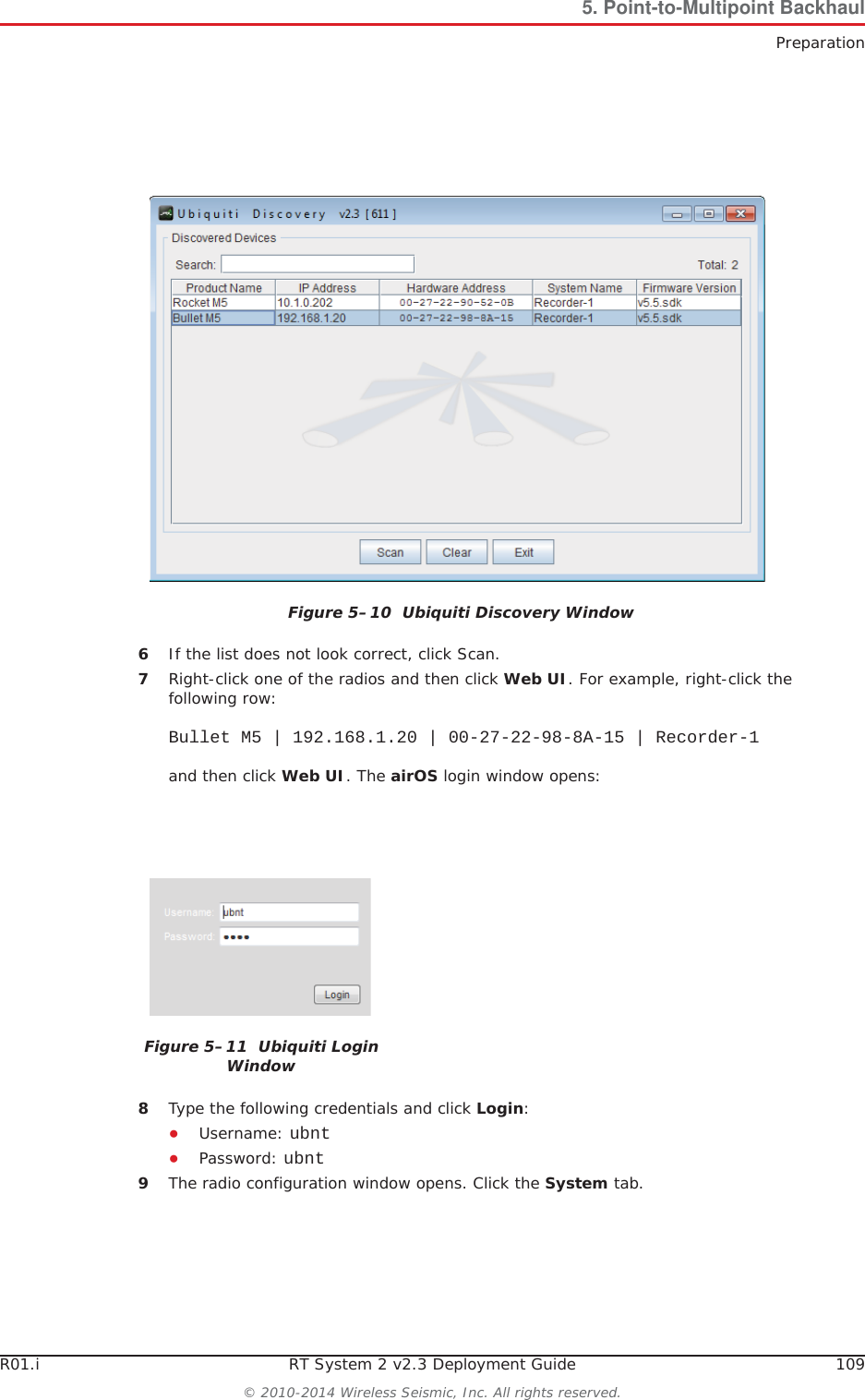
00106 User Manual
>
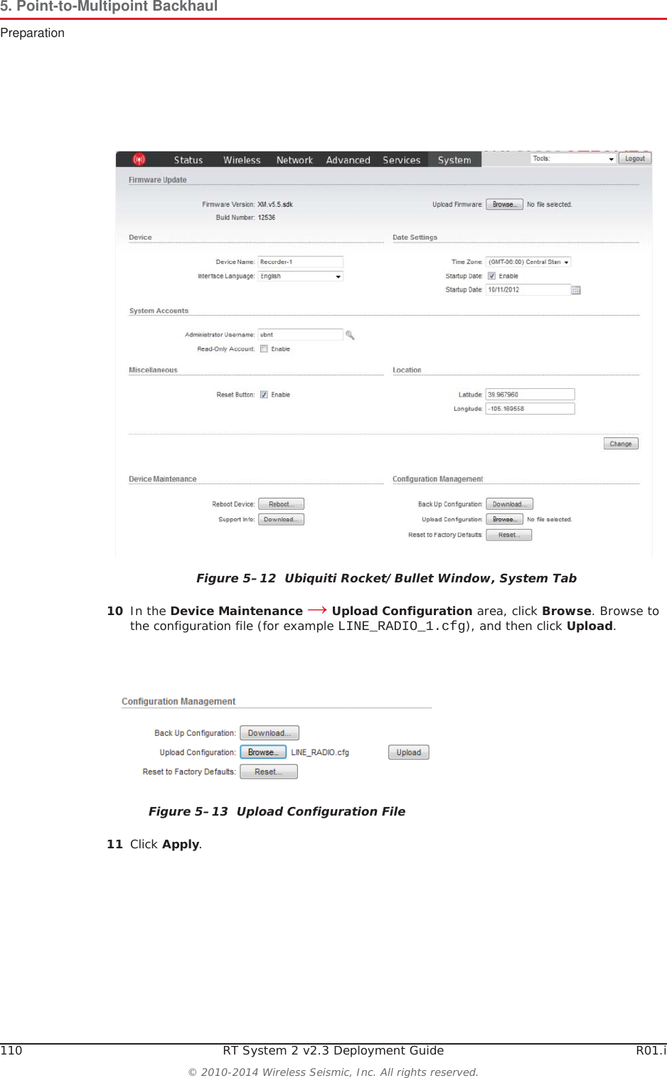
User Manual Part 1
Contents
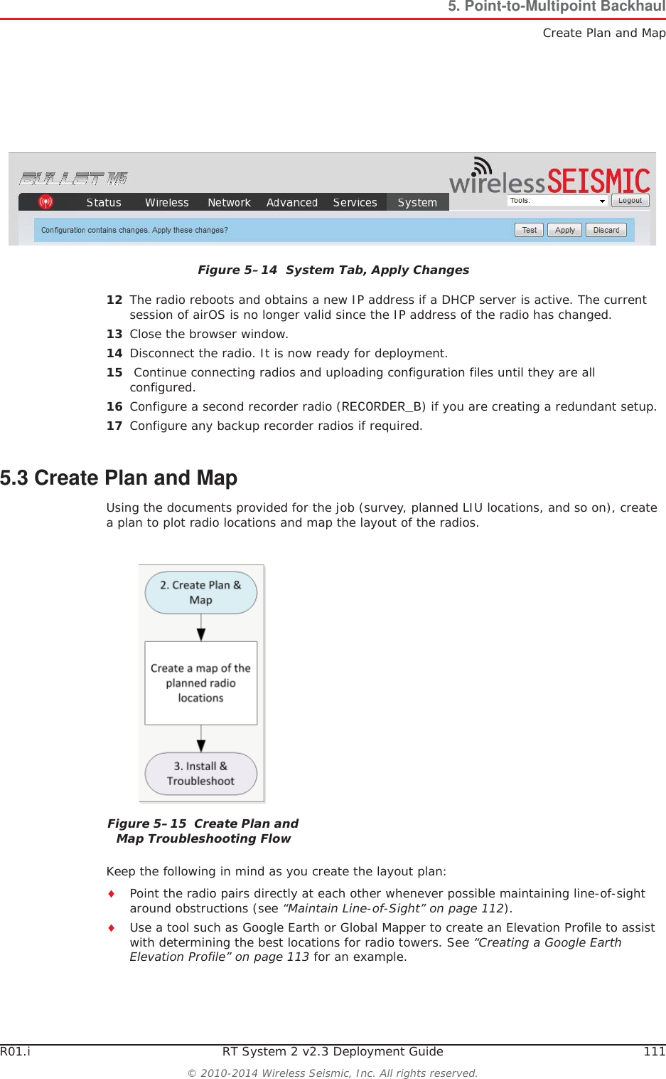
1.
User Manual Part 1
2.
User Manual Part 2
User Manual Part 1
Navigation menu
Upload a User Manual
Namespaces
Wiki Guide
HTML
PDF
Info
Views
User Manual
Discussion / Help
Navigation
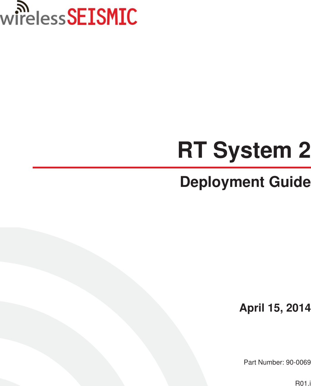

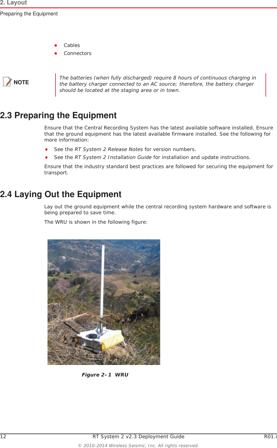
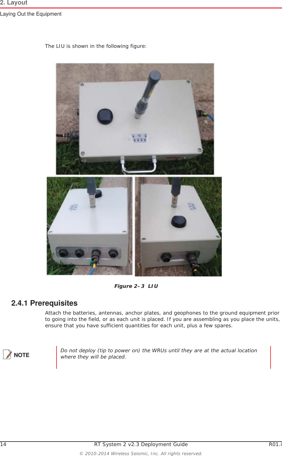
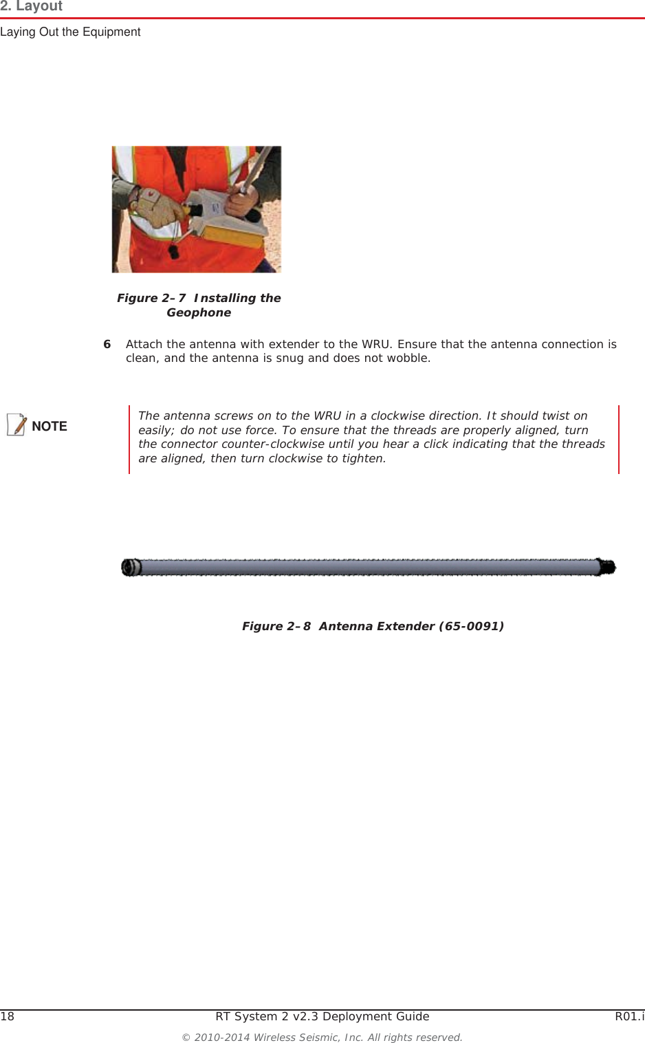

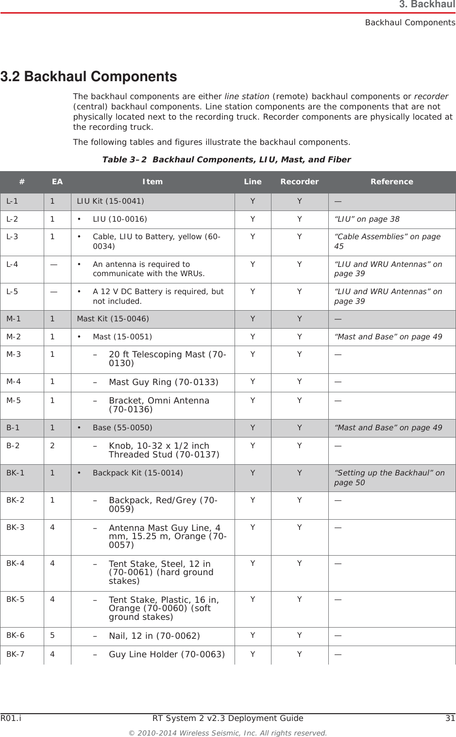
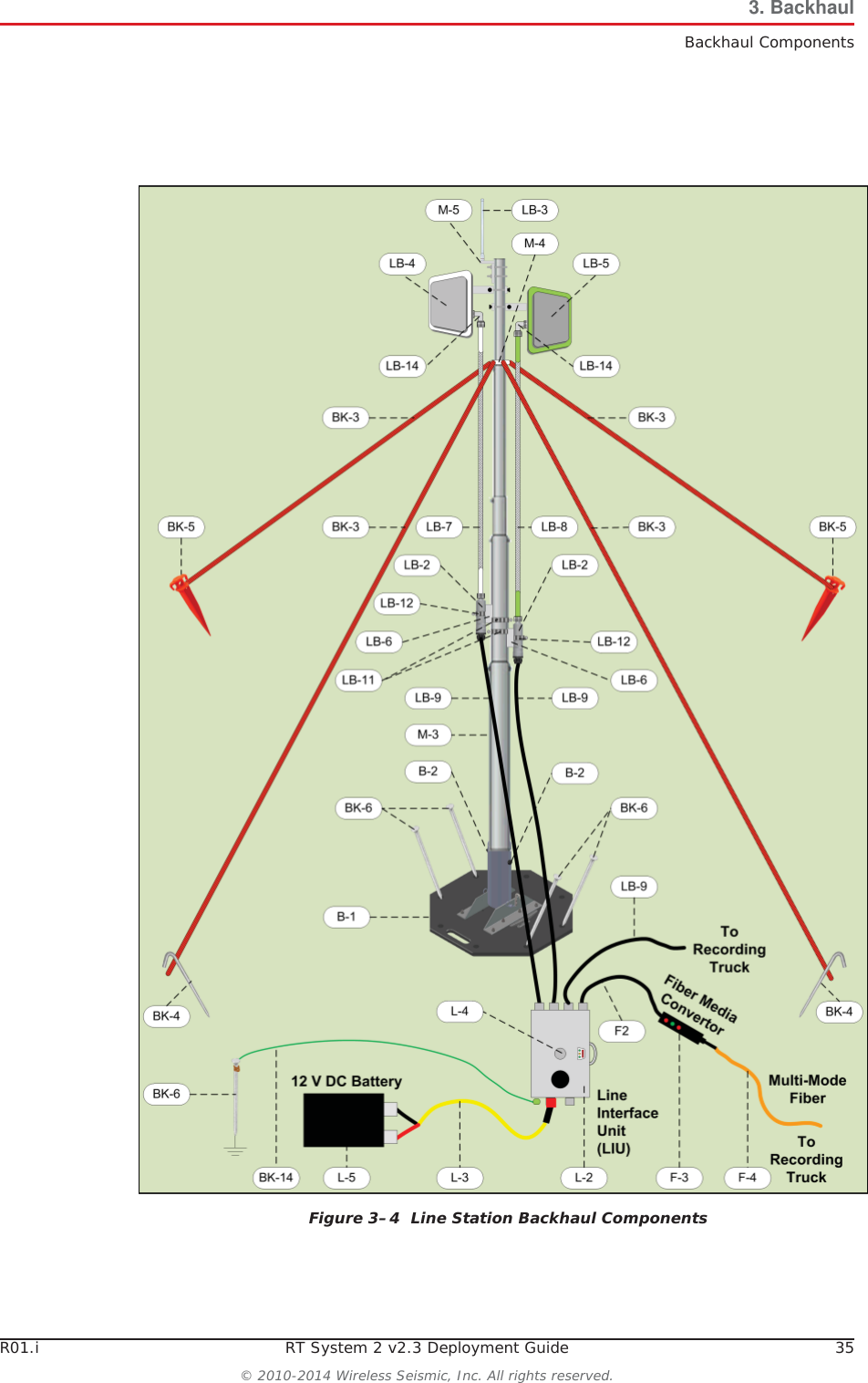
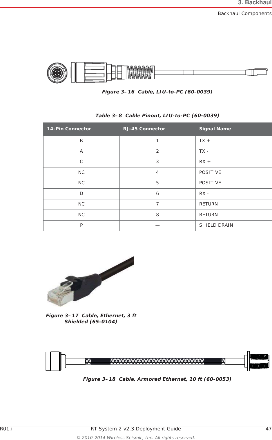
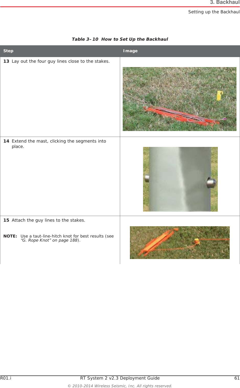
![R01.i RT System 2 v2.3 Deployment Guide 51© 2010-2014 Wireless Seismic, Inc. All rights reserved.3. BackhaulSetting up the BackhaulƔIf the wind is blowing, the mast is more stable when the brackets are perpendicular to the wind.5Secure the base [B-1] to the ground with stakes [BK-4] or nails [BK-6]. 6Attach the mast [M-3] to the base [B-1]. Tighten both knobs [B-2].Table 3–10 How to Set Up the BackhaulStep Image](https://usermanual.wiki/Wireless-Seismic/00106.User-Manual-Part-1/User-Guide-2306421-Page-51.png)
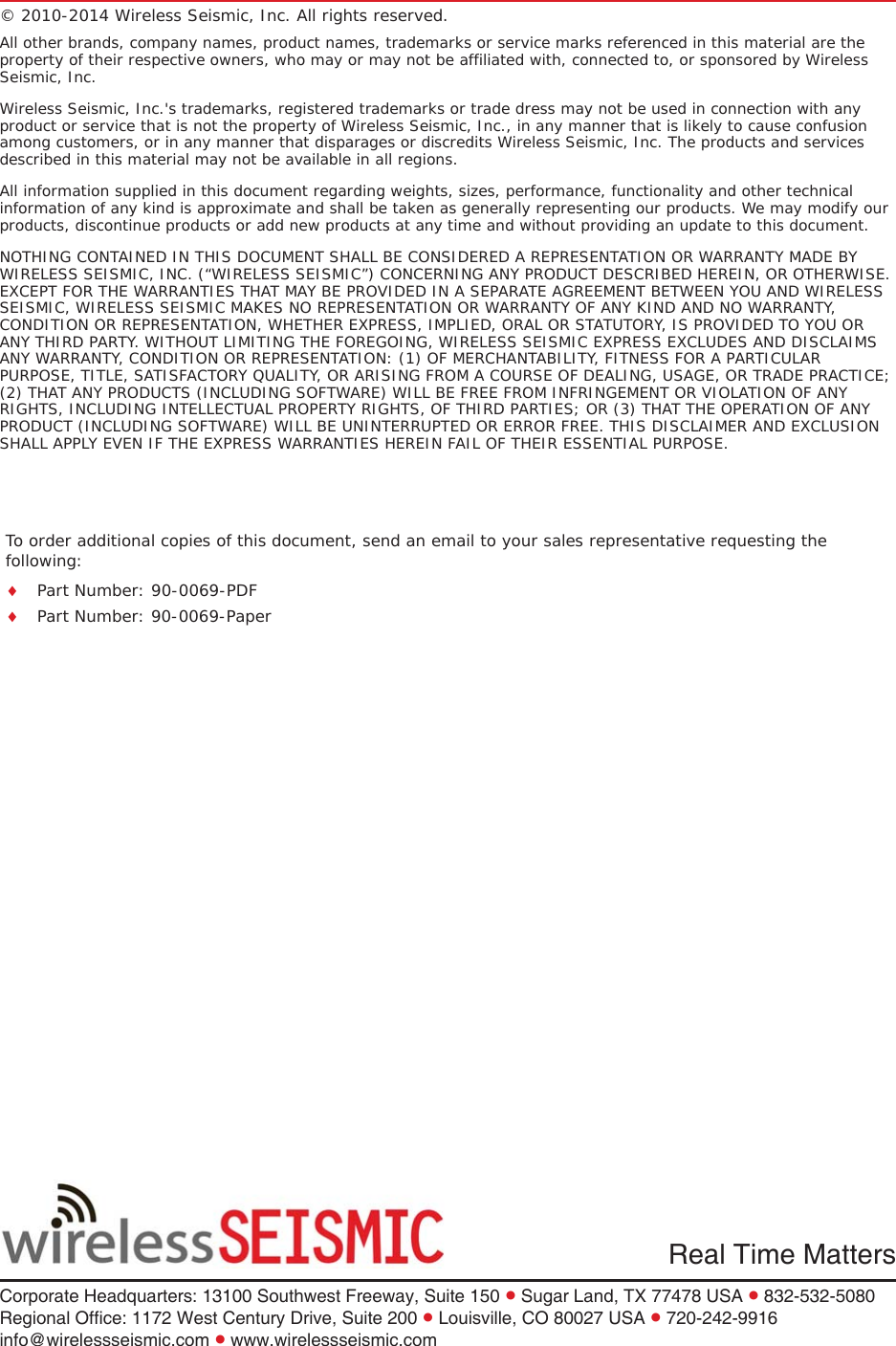
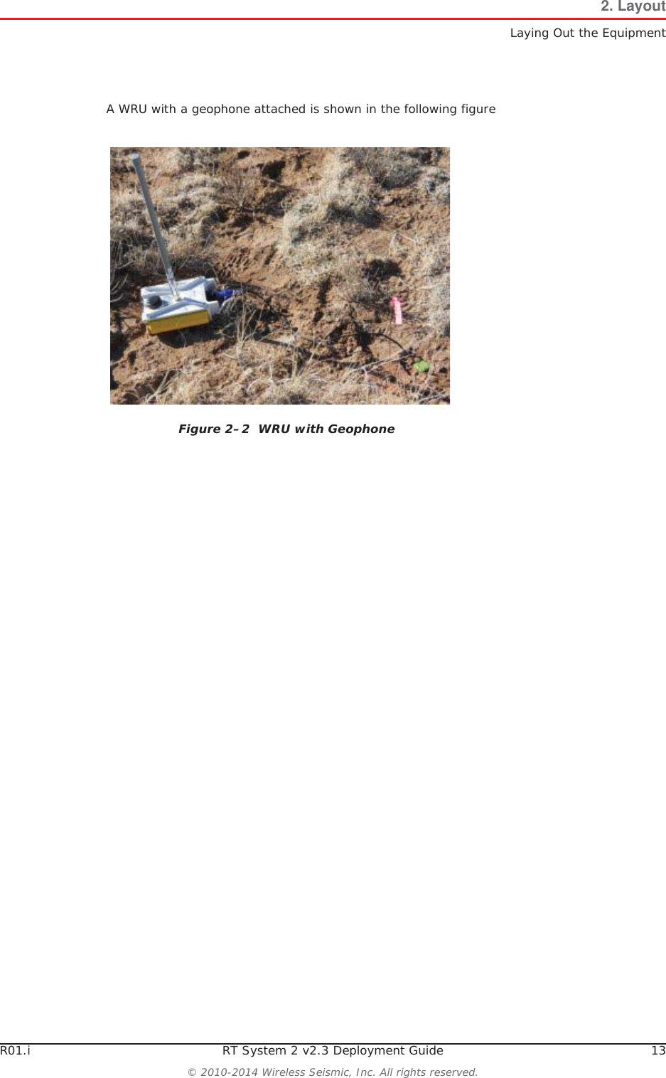
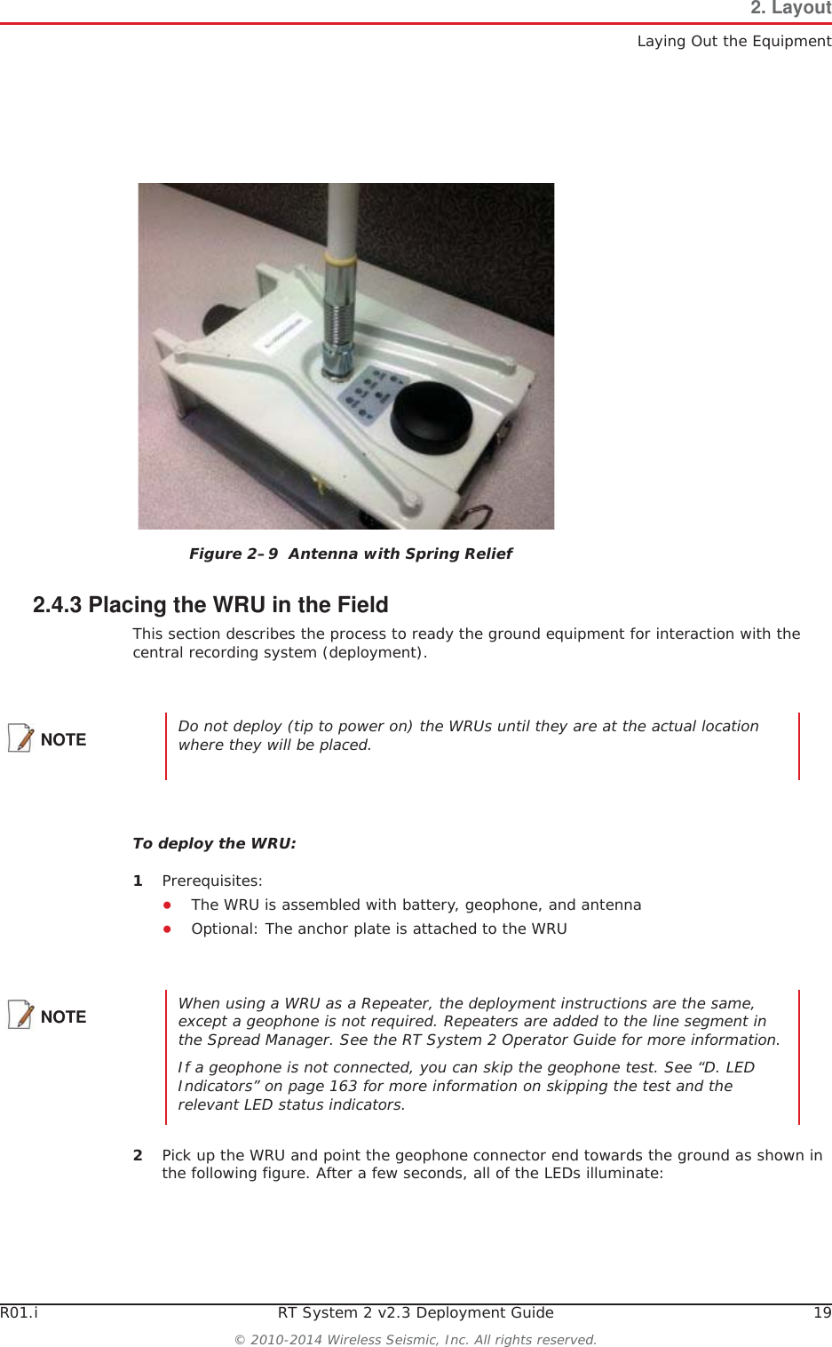
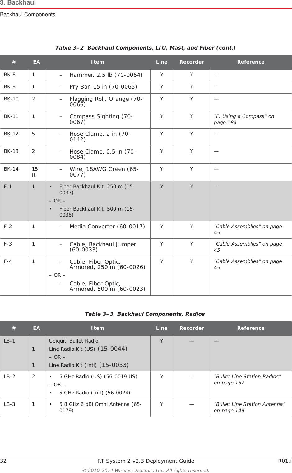
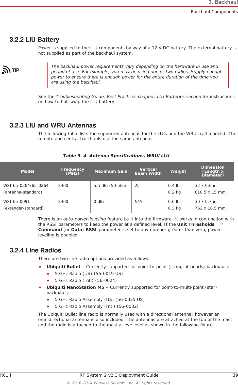
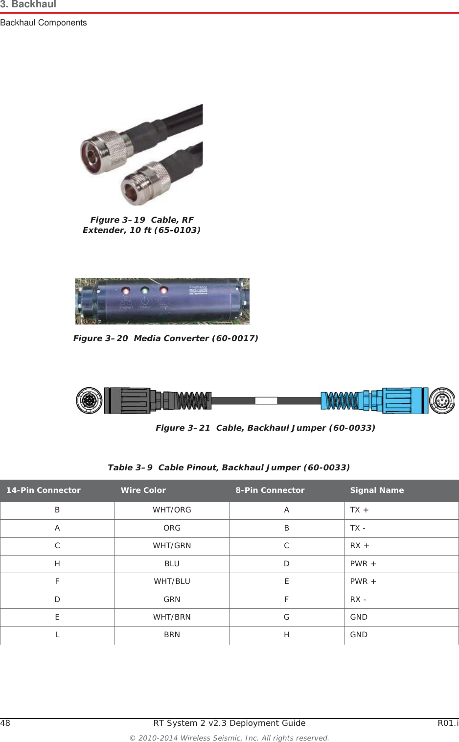
![52 RT System 2 v2.3 Deployment Guide R01.i© 2010-2014 Wireless Seismic, Inc. All rights reserved.3. BackhaulSetting up the Backhaul7Position four stakes equal distances apart at approximately 20 ft (6 m) from the base. Pound them into the ground. 8Assemble the radios and brackets:ƔBullet line radio installation – Assemble the Bullet radios and brackets.ŹInsert the 4 in hose clamp [LR-11] in the side slots of the bracket [LR-6].ŹInsert the 2 in hose clamp [LR-12] in the center slots of the bracket [LR-6].ŹInsert the line radio between the bracket [LR-6] and the 2 in hose clamp [LR-12].ŹTighten the 2 in hose clamp [LR-12]around the radio. Line radio in bracket:Table 3–10 How to Set Up the BackhaulStep Image](https://usermanual.wiki/Wireless-Seismic/00106.User-Manual-Part-1/User-Guide-2306421-Page-52.png)
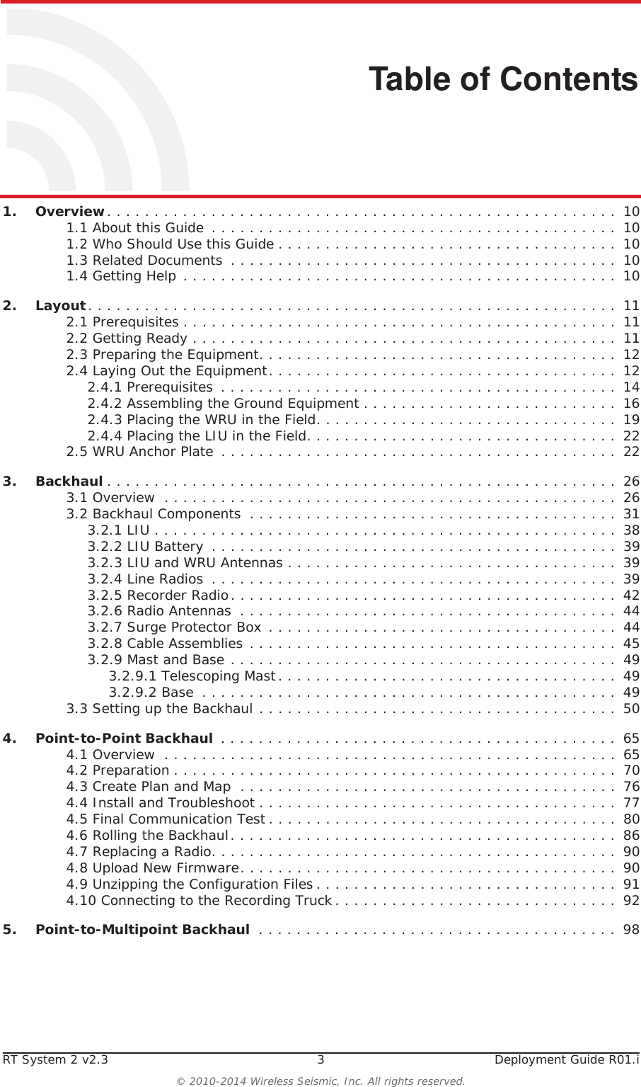
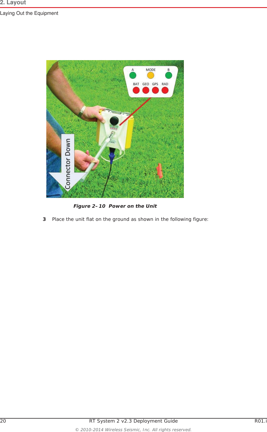
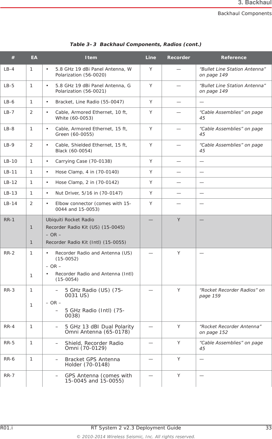
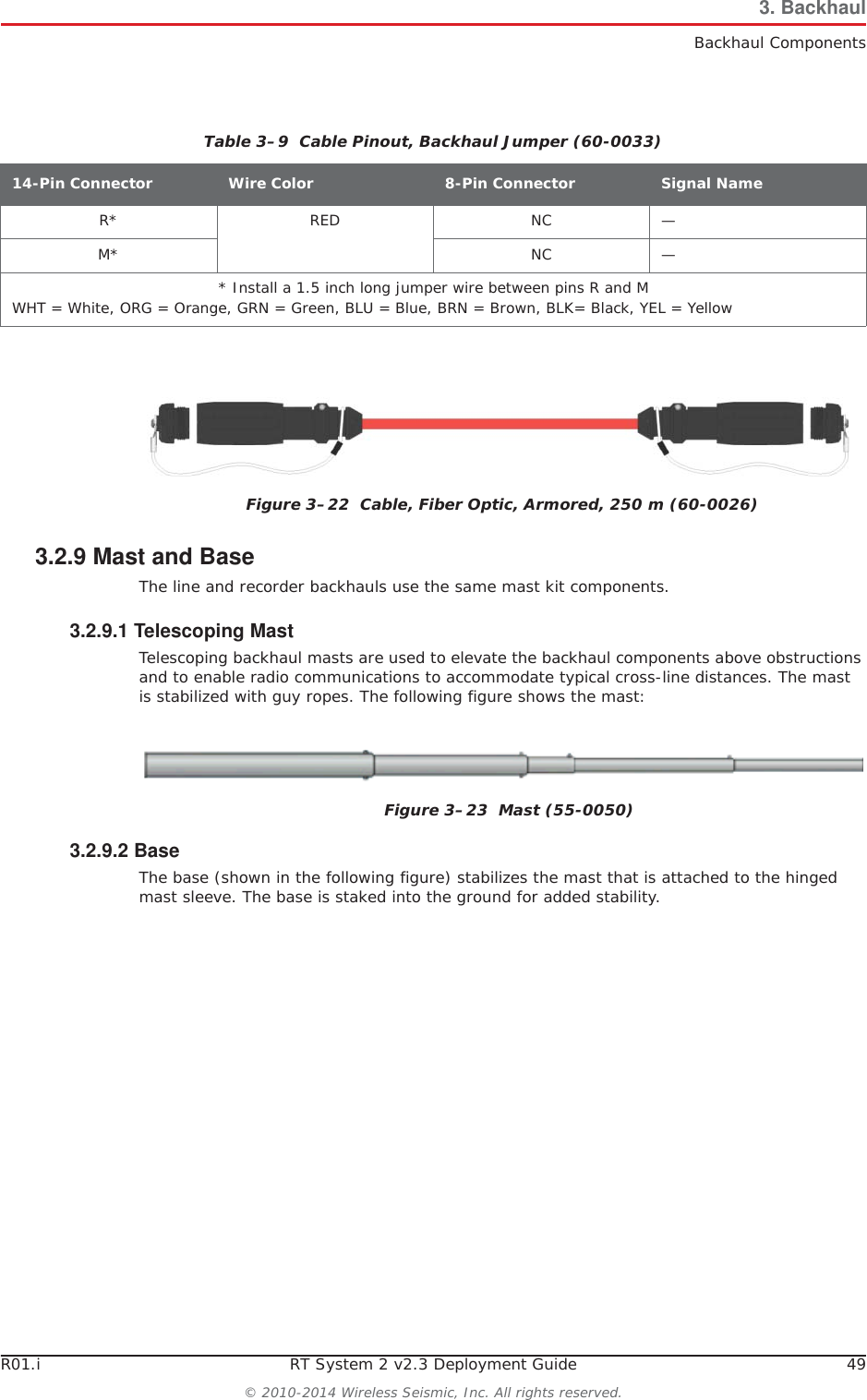
![54 RT System 2 v2.3 Deployment Guide R01.i© 2010-2014 Wireless Seismic, Inc. All rights reserved.3. BackhaulSetting up the Backhaul9Assemble the mast:ƔBullet radio installation – While the mast is resting on the ground, slide the following on the mast:ŹBullet radios and clamps (do not tighten)ŹMast guy ring [M-4]Table 3–10 How to Set Up the BackhaulStep Image](https://usermanual.wiki/Wireless-Seismic/00106.User-Manual-Part-1/User-Guide-2306421-Page-54.png)
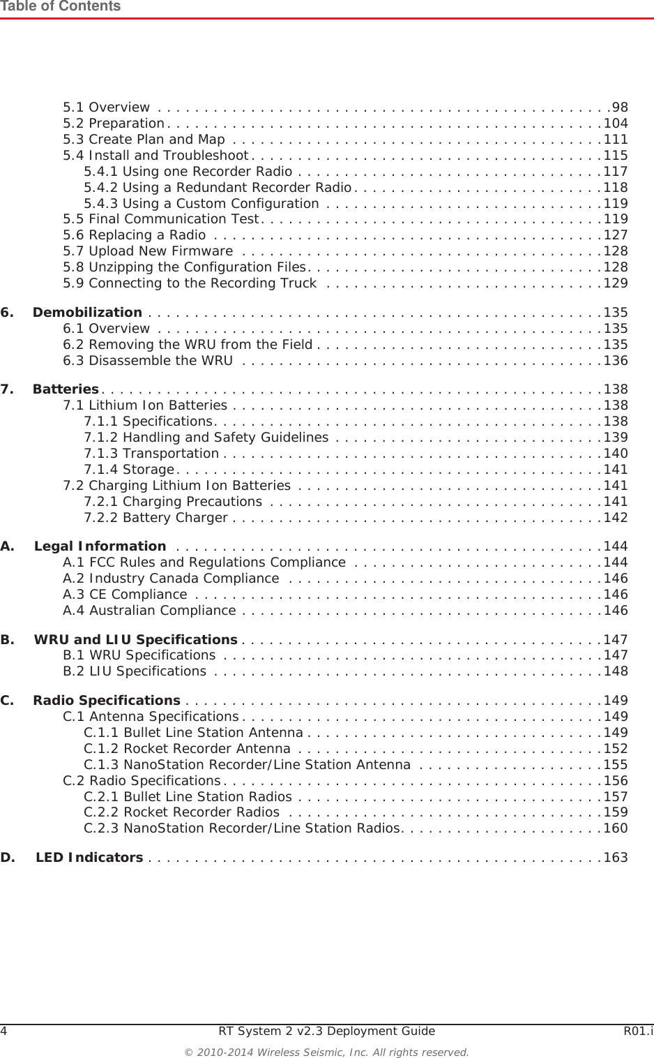
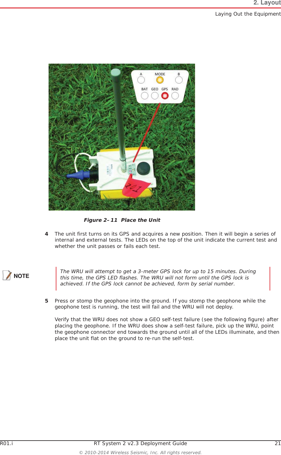
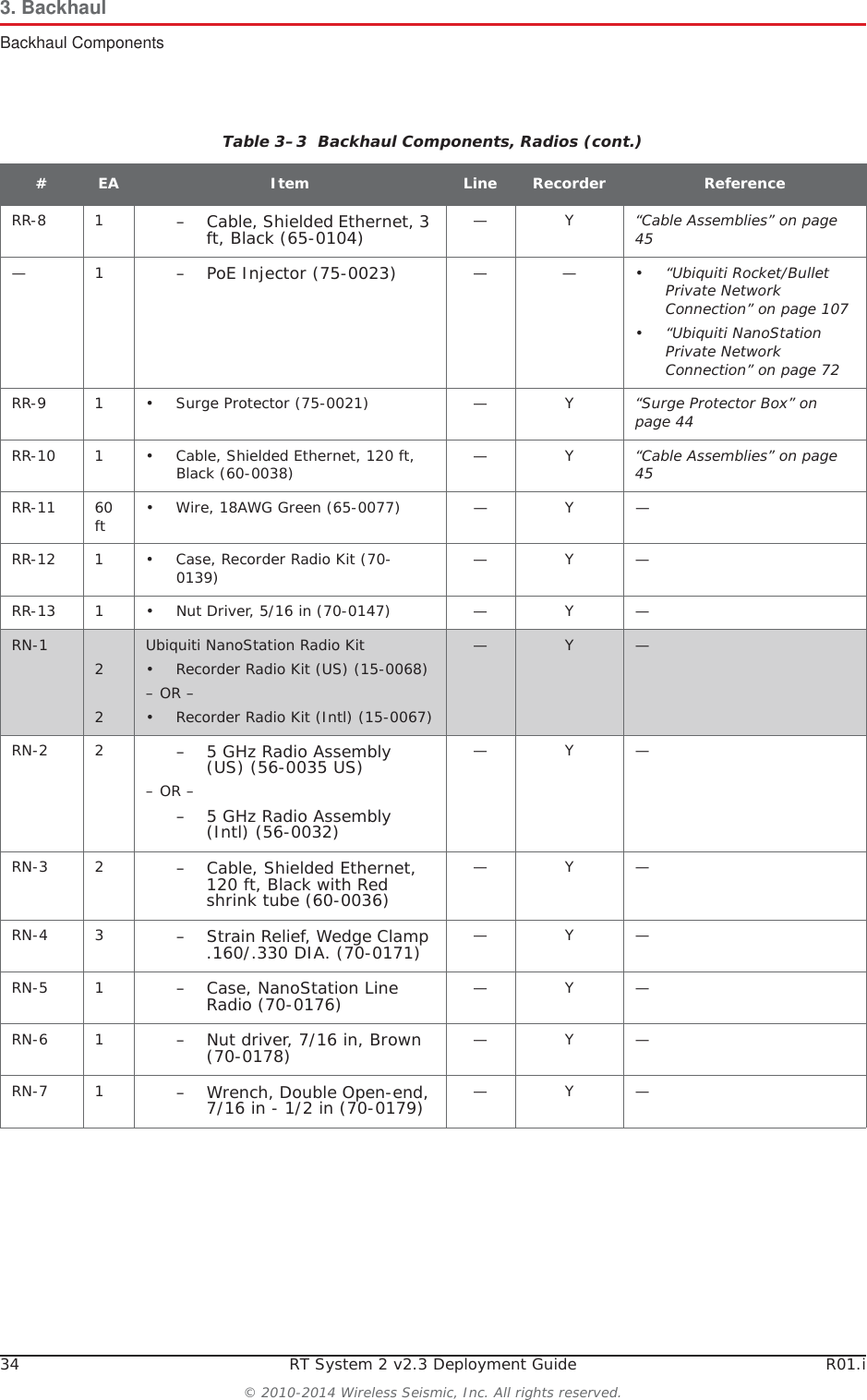
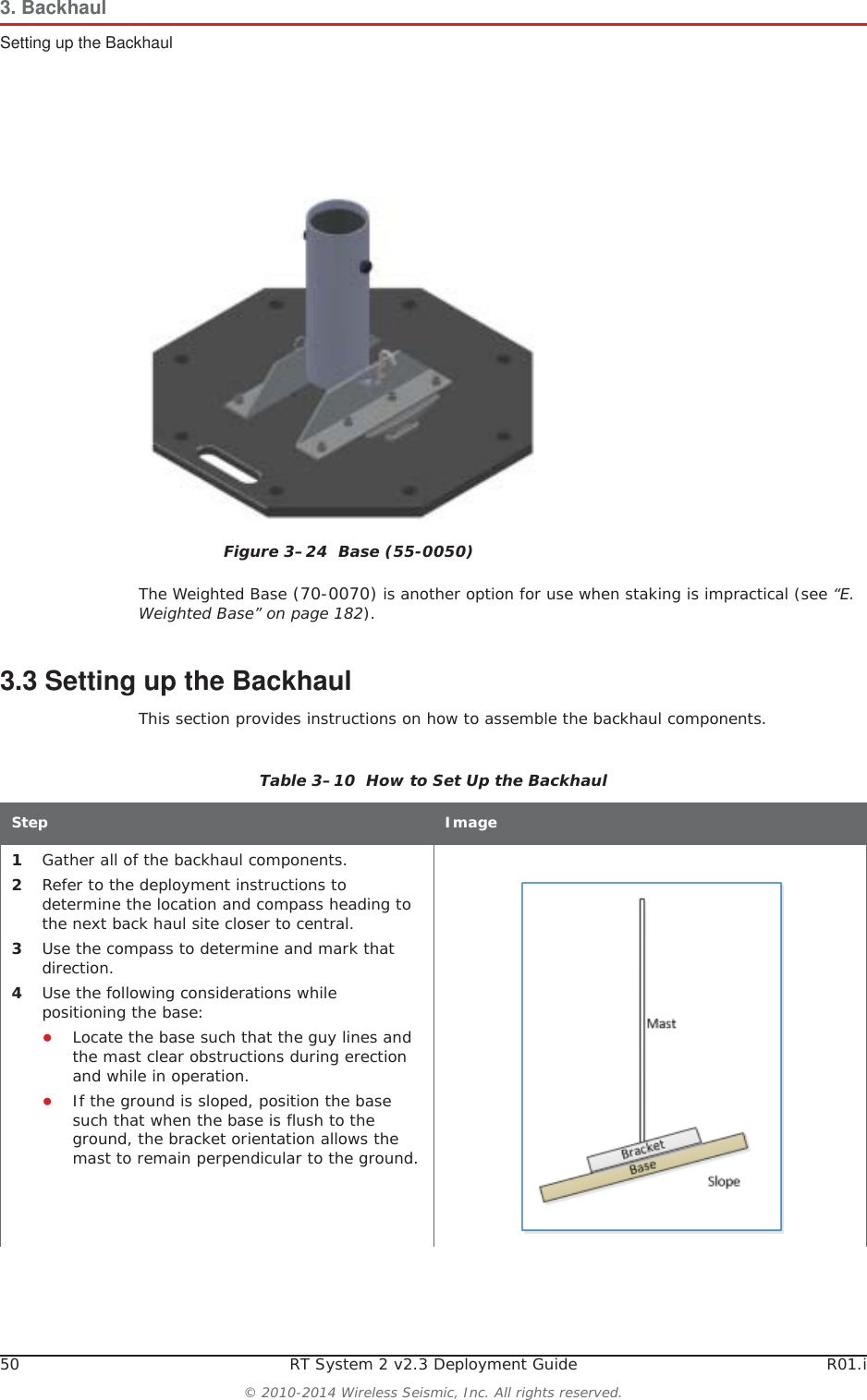
![R01.i RT System 2 v2.3 Deployment Guide 55© 2010-2014 Wireless Seismic, Inc. All rights reserved.3. BackhaulSetting up the BackhaulƔRocket radio installation – While the mast is resting on the ground, slide the following on the mast:ŹMast guy ring [M-4] ŹSurge Protector cable clamp (do not tighten)Table 3–10 How to Set Up the BackhaulStep Image](https://usermanual.wiki/Wireless-Seismic/00106.User-Manual-Part-1/User-Guide-2306421-Page-55.png)
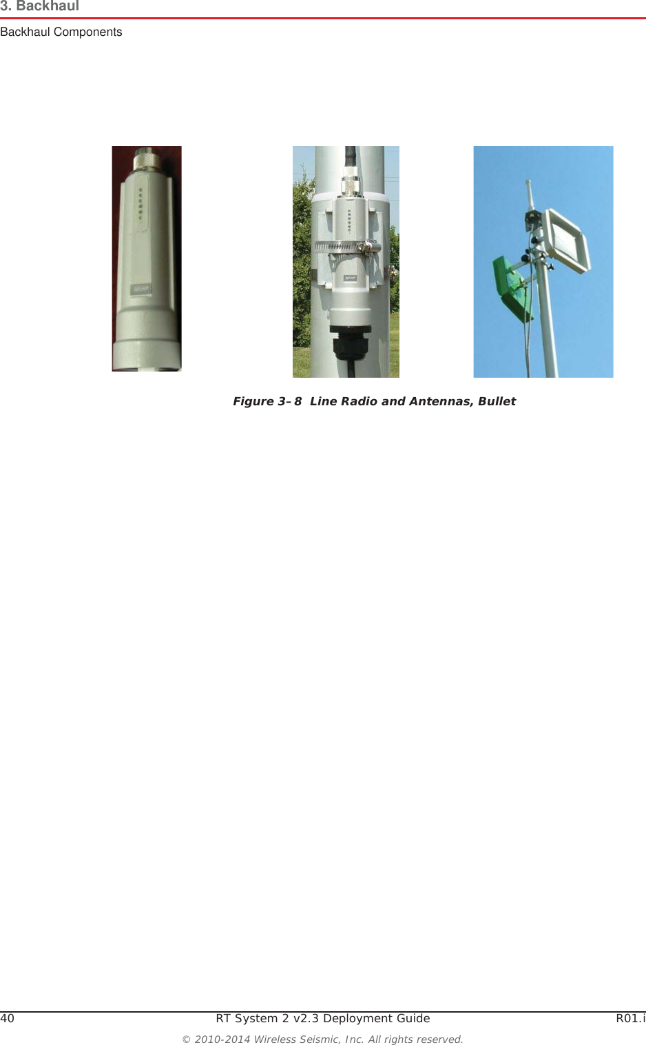
![56 RT System 2 v2.3 Deployment Guide R01.i© 2010-2014 Wireless Seismic, Inc. All rights reserved.3. BackhaulSetting up the BackhaulƔNanoStation radio installation – While the mast is resting on the ground, slide the following on the mast:ŹMast guy ring [M-4] 10 Attach and tighten the following:ƔBullet radio installation:ŹBullet radio antenna brackets and antennas [LR-4, LR-5]ŹOmni antenna bracket [M-5] and antenna [LR-3]Table 3–10 How to Set Up the BackhaulStep Image](https://usermanual.wiki/Wireless-Seismic/00106.User-Manual-Part-1/User-Guide-2306421-Page-56.png)
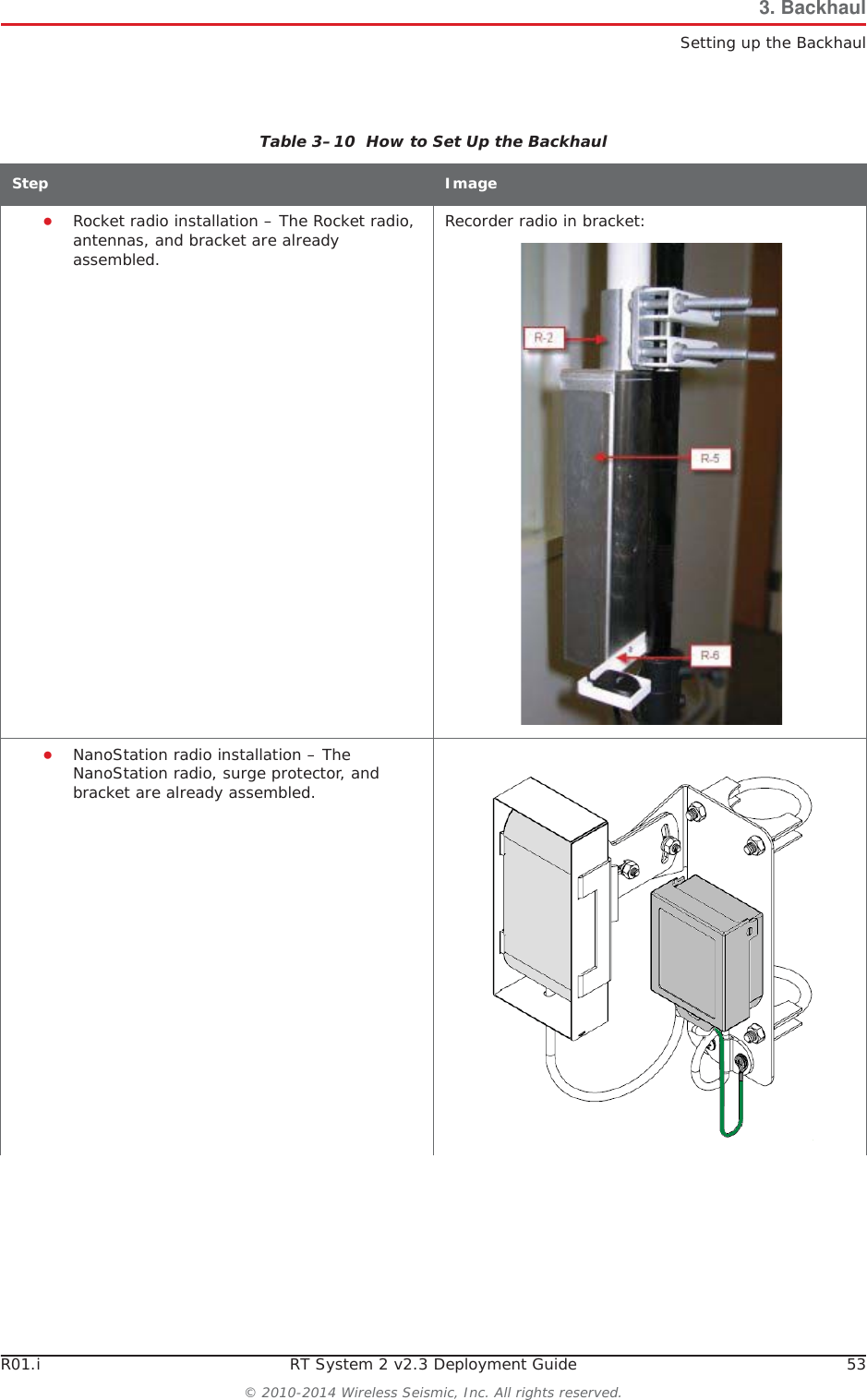
![R01.i RT System 2 v2.3 Deployment Guide 57© 2010-2014 Wireless Seismic, Inc. All rights reserved.3. BackhaulSetting up the BackhaulƔRocket radio installation – Attach the Rocket radio antenna and bracket [R-2] to the mast.Table 3–10 How to Set Up the BackhaulStep Image](https://usermanual.wiki/Wireless-Seismic/00106.User-Manual-Part-1/User-Guide-2306421-Page-57.png)
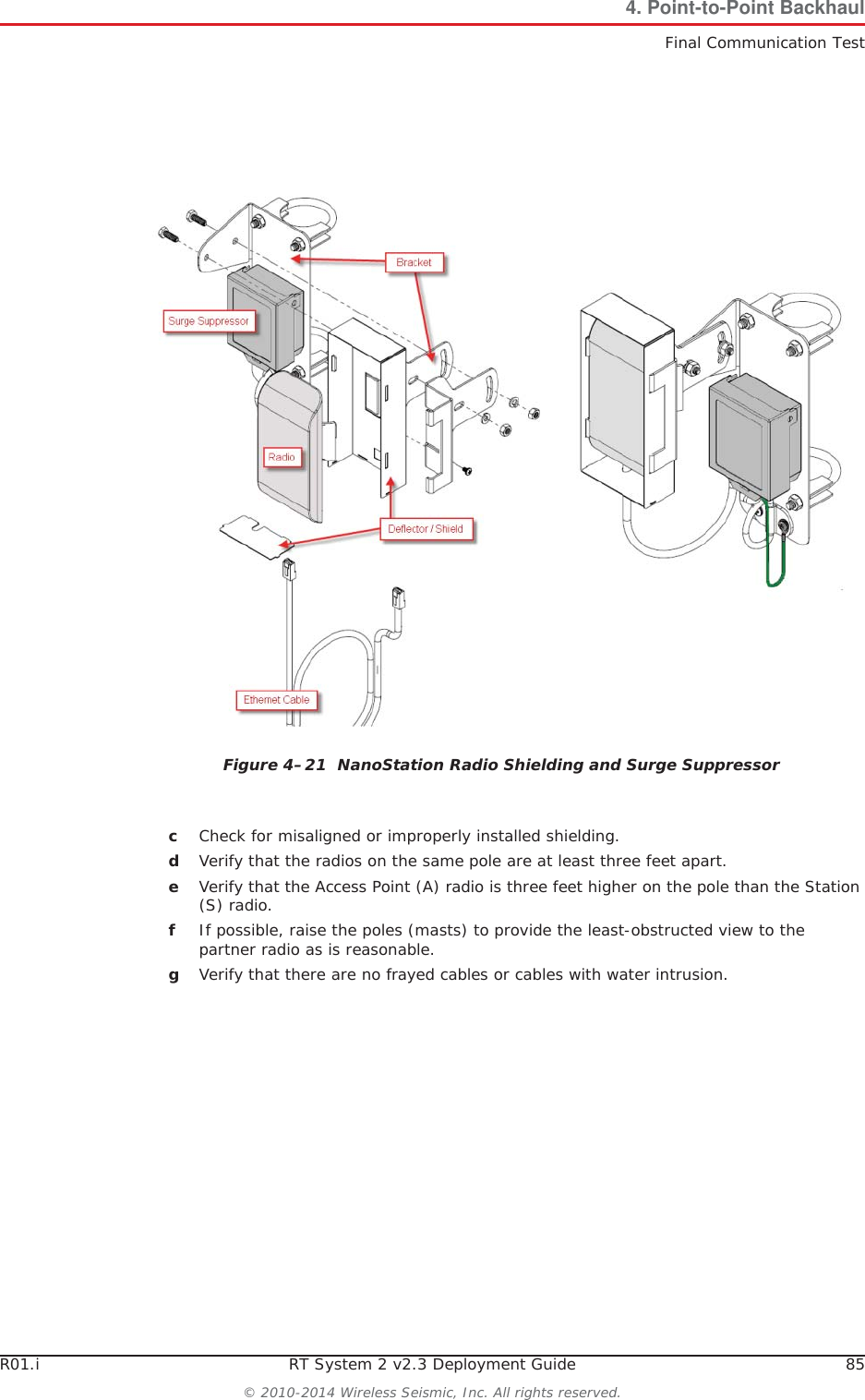
![58 RT System 2 v2.3 Deployment Guide R01.i© 2010-2014 Wireless Seismic, Inc. All rights reserved.3. BackhaulSetting up the BackhaulƔNanoStation radio installation – Attach the NanoStation radio bracket assembly [RN-2] to the mast.Table 3–10 How to Set Up the BackhaulStep Image](https://usermanual.wiki/Wireless-Seismic/00106.User-Manual-Part-1/User-Guide-2306421-Page-58.png)
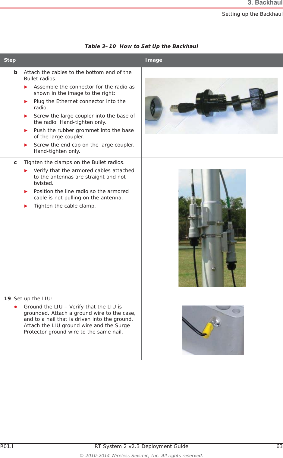
![R01.i RT System 2 v2.3 Deployment Guide 59© 2010-2014 Wireless Seismic, Inc. All rights reserved.3. BackhaulSetting up the Backhaul11 Attach the cables:ƔBullet radio installation – Attach an elbow connector [LR-14] to the antenna and then an armored cable [LR-7, LR-8] to the elbow connector. Match white-to-white and green-to-green if your panels are color-coded. ƔRocket radio installation:ŹOpen the protective metal case if the Ethernet cable is not already attached.ŹConnect the GPS antenna if it is not already connected.ŹConnect a short Ethernet cable [R-8] to the radio [R-3]. ŹClose the protective metal case.ŹOpen the surge protector case [R-9]. ŹRemove the rubber grommet from the surge protector case and cut some slots in it. ŹThread two Ethernet cables [R-8, R-10] and a ground wire [BK-14] through the grommet and place the grommet back in the case.ŹPlug the Ethernet cables into the shielded RJ45 jacks. It does not matter which cable goes to which jack; the unit provides bidirectional protection.ŹAttach the ground wire to the ground lug.ŹClose the surge protector case and secure it to the mast with the hose clamp.Table 3–10 How to Set Up the BackhaulStep Image](https://usermanual.wiki/Wireless-Seismic/00106.User-Manual-Part-1/User-Guide-2306421-Page-59.png)
![60 RT System 2 v2.3 Deployment Guide R01.i© 2010-2014 Wireless Seismic, Inc. All rights reserved.3. BackhaulSetting up the BackhaulƔNanoStation radio installation:ŹOpen the surge protector case [R-9]. ŹRemove the grommet from the case.ŹThread the Ethernet cable [RN-3], through the grommet with the short Ethernet cable (that is attached to the redound the ground wire [BK-14]. Place the grommet back in the case.ŹPlug the Ethernet cable into the shielded RJ45 jacks. It does not matter which cable goes to which jack; the unit provides bidirectional protection.ŹClose the surge protector case.ŹAttache the strain relief [RN-4] to the D-ring on the bracket.ŹLoop the Ethernet Cable [RN-3] through the strain relief [RN-4].12 Attach the guy lines to the mast collar.NOTE: Use a taut-line-hitch knot for best results (see “G. Rope Knot” on page 188). Table 3–10 How to Set Up the BackhaulStep Image](https://usermanual.wiki/Wireless-Seismic/00106.User-Manual-Part-1/User-Guide-2306421-Page-60.png)