Wireless N2WLAX-5G3 UNII WLAN User Manual N2 Link Cover
Wireless Inc UNII WLAN N2 Link Cover
Wireless >
Contents
USER MANUAL

WaveNet Link AX
ATM-25 U-NII Band
Digital Radio System
Installation and Operations Manual
Part Number 100273-001
Version 0.8
October 2000
Wireless Inc.
5452 Betsy Ross Drive
Santa Clara, CA. 95054-1101
(408) 727-8383

ii
WaveNet Link AX Installation and Operations Manual
Notice
Information in this document is subject to change without notice. No part of this document may
be reproduced or transmitted in any form or by any means, electronic or mechanical, for any
purpose, without the express written permission of Wireless, Inc.
© Copyright 2000, Wireless, Inc. All rights reserved.
Link AX™ and WaveNet Link™ Series are trademarks of Wireless, Inc.

iii
WaveNet Link AX Installation and Operations Manual
Table of Contents
1.0 General Overview ................................................................................................................. 1
1.1 WaveNet Link Series Product Family........................................................................ 1
1.2 Introduction to the Link AX ........................................................................................ 1
1.3 Regulatory Information .............................................................................................. 2
2.0 Link AX Product Profile ......................................................................................................... 3
2.1 General Overview...................................................................................................... 3
2.2 Specifications ............................................................................................................ 5
2.3 User Interfaces .......................................................................................................... 8
2.4 ODU Performance Monitoring ................................................................................... 8
2.5 Theory of Operation .................................................................................................. 9
3.0 Equipment Installation and Commissioning ........................................................................ 15
3.1 Installation ............................................................................................................... 15
3.2 ATM25 Data Connectors ......................................................................................... 19
3.3 Connect the Power Supply ...................................................................................... 19
3.4 Outdoor RF Unit Installation .................................................................................... 20
3.5 Indoor Unit ............................................................................................................... 27
3.6 DIP Switch Function and Configuration .................................................................. 28
3.7 Commissioning ........................................................................................................ 30
4.0 Antenna Installation............................................................................................................. 35
4.1 Equipment Inventory List ......................................................................................... 35
4.2 Antenna Installation and Rough Alignment ............................................................. 36
4.3 RF Cable Install and Seal........................................................................................ 50
5.0 Maintenance and Troubleshooting...................................................................................... 63
5.1 Link AX Maintenance .............................................................................................. 63
5.2 Where to get Further Assistance............................................................................. 64
5.3 Return Procedure .................................................................................................... 65
Appendix A Grounding Practices and Lightning Protection Information....................................... A-1

iv
WaveNet Link AX Installation and Operations Manual
Figures
Figure 2.1 Typical Deployment of a Link AX in a Point-to-Point Configuration ............................. 4
Figure 2.2a Outdoor Unit, Front View ............................................................................................ 10
Figure 2.2b Outdoor Unit, Back View ............................................................................................ 10
Figure 2.2c Outdoor Unit, Front View, Integral Antenna ............................................................... 11
Figure 2.2d Outdoor Unit, Back View, Integral Antenna ............................................................... 11
Figure 2.3 Link AX Indoor Unit (IDU) ........................................................................................... 13
Figure 2.4 Link AX Block Diagram............................................................................................... 14
Figure 3.1 Power Cord Connection ............................................................................................. 19
Figure 3.2 Outdoor Unit Mounting Hardware .............................................................................. 20
Figure 3.3 Attaching the Pole or Tilt Mount Adaptor Bracket ...................................................... 21
Figure 3.4 Mounting the Outdoor RF Unit to the Bracket ............................................................ 22
Figure 3.5a Mounting Bracket Latch and Stud Mount Detail......................................................... 23
Figure 3.5b Locking the Mounting Hardware ................................................................................ 24
Figure 3.6a N-Type Antenna and Siamesed Ethernet/Power Connections .................................. 25
Figure 3.6b Ground Connection ....................................................................................................26
Figure 3.7 Link Ax Indoor Unit (IDU) ........................................................................................... 27
Figure 3.8 DIP Switch Access and Configuration Information .................................................... 29
Figure 3.9 Receive Signal Level ..................................................................................................34
Figure 4.1 Antenna Mount ........................................................................................................... 36
Figure 4.2 Adjustable Panel Antenna Mount ............................................................................... 37
Figure 4.3 Flat Panel Antenna ..................................................................................................... 38
Figure 4.4 Adjustable Flat Panel Mount ...................................................................................... 39
Figure 4.5 24” Flat Panel Quick Align Mount............................................................................... 40
Figure 4.6 24” Diameter Antenna ................................................................................................ 41
Figure 4.7 Mount Configuration ...................................................................................................43
Figure 4.8 Mounting Hardware Packed ....................................................................................... 46
Figure 4.9 Mounting Hardware Unpacked ................................................................................... 46
Figure 4.10 Parabolic Reflector ..................................................................................................... 47
Figure 4.11 Unpacking the Radome .............................................................................................. 47
Figure 4.12 Antenna Mounting Assembly ..................................................................................... 48
Figure 4.13 Antenna Mount Assembly .......................................................................................... 49
Figure 4.14 Elevation Rod Assembly ............................................................................................ 49
Figure 4.15 Feed Horn Assembly .................................................................................................. 50
Figure 4.16 Feed Horn Polarization Markings ............................................................................... 51
Figure 4.17 Parabola Rear View Showing Polarization Reference Markers ................................. 51
Figure 4.18 Feed Horn Installation ................................................................................................ 52
Figure 4.19 Feed Horn Installation for Vertical Polarized Operation ............................................. 52
Figure 4.20 Azimuth Clamp/Shear Stop Assembly ....................................................................... 53

v
WaveNet Link AX Installation and Operations Manual
Figure 4.21 Azimuth Adjustment Clamp Assembly ...................................................................... 53
Figure 4.22 Hoisting the Antenna ................................................................................................. 54
Figure 4.23 Adjustable Parabolic Antenna Mount ....................................................................... 57
Figure 4.24a Feed Assembly Plane Polarized ............................................................................... 58
Figure 4.24b Feed Assembly Plane Polarized ............................................................................... 59
Figure 4.25 Ground Connection ...................................................................................................60
Figure 4.26 RF Cable Install and Seal ......................................................................................... 61
Tables
Table 1.1 FCC U-NII Bands ......................................................................................................... 2
Table 2.1 Connector Pin Assignment, ATM Connector on ODU ................................................. 6
Table 2.2 Connector Pin Assignment, Power Supply Input Connector on ODU ......................... 6
Table 2.3 Recommended Antennas ............................................................................................. 7
Table 3.1 Maximum Transmit Power Level Setting vs. Antenna Type (for compliance with
FCC EIRP limits) in the 5.3 GHz Band....................................................................... 16
Table 3.2 Maximum Transmit Power Level Setting vs. Antenna Type (for compliance with
FCC EIRP limits) in the 5.7 GHz Band, Original and July 31, 1998 rules.................. 17
Table 3.3 List of Tools ................................................................................................................ 18
Table 3.4 Inventory of Equipment and Installation Materials ..................................................... 18
Table 3.5 Connector Pin Assignment, ATM Connector on ODU ............................................... 19
Table 3.6a Connector Pin Assignment, ATM Connector on ODU ............................................... 27
Table 3.6b Connector Pin Assignment, ATM Connector on ODU ............................................... 27
Table 3.6c IDU LED Status .......................................................................................................... 27
Table 3.7 DIP Switch Configuration ........................................................................................... 28
Table 3.8 Installation Checklist................................................................................................... 30
Table 3.9 RSSI Voltage vs. Receive Signal Level ..................................................................... 32
Table 3.10 Approximation Table .................................................................................................. 32
Table 4.1 Inventory of Equipment and Installation Materials ..................................................... 35
Table 4.2 Approximation Table of Flat Panel Antennas............................................................. 36
Table 4.3 Approximation Table of Parabolic Antennas .............................................................. 41
Table 4.4 24” Diameter Antenna Dimensions ............................................................................ 42
Table 4.5a Contents List, Mount Assembly.................................................................................. 44
Table 4.5b Contents List, Mount Assembly.................................................................................. 45
Table 4.5c Contents List, Feed Assembly ................................................................................... 45
Table 4.5d Contents List, Reflector Assembly ............................................................................. 45
Table 4.6 Nut Tightening Procedures ........................................................................................ 56

vi
WaveNet Link AX Installation and Operations Manual
Welcome!
Welcome to the Wireless, Inc. WaveNet Link™ Series product family. This manual is designed
to introduce you to the Link AX™, and to provide you with information necessary to plan, install,
operate and maintain a Link AX wireless communication system.
The Link AX is intended for professional installation only. This manual, however, is also
designed for personnel who plan, operate and administrate the Link AX communication system.
Please review the entire manual before powering up or deploying any Link AX.
Updates to this manual will be posted on the Wireless, Inc. Customer Service Website at
http://www.wire-less-inc.com
. Registered Wireless customers can access Wireless’ on-line
information and support service, available 24 hours a day, 7 days a week. Our on-line service
provides users with a wealth of up-to-date information, with documents being added or updated
each month.
Radiation Warnings
Microwave Radio Radiation Warning
Under normal operating conditions, Link AX radio equipment complies with the limits for human
exposure to radio frequency (RF) fields adopted by the Federal Communications Commission
(FCC). All Wireless, Inc. microwave radio equipment is designed so that under normal working
conditions, microwave radiation directly from the radio is negligible when compared with the
permissible limit of continuous daily exposure recommended in the United States by ANSI/IEEE
C95.1-1991 (R1997), Safety Levels with Respect to Human Exposure to Radio Frequency
Electromagnetic Fields, 3 kHz to 300 GHz.
Microwave signal levels that give rise to hazardous radiation levels can exist within transmitter
power amplifiers, associated RF multiplexers, and antenna systems.
Never look into the open end of a Waveguide as eyes are particularly vulnerable to radiation.
Do not disconnect RF coaxial connectors, open microwave units, or break down any
microwave screening while the radio equipment is operating.

vii
WaveNet Link AX Installation and Operations Manual
Microwave Antenna Radiation Warning
Designed for point-to-point operation, a Link AX microwave radio system uses directional
antennas to transmit and receive microwave signals. These directional antennas are usually
circular or rectangular in shape, and are usually mounted outdoors on a tower or mast, well
above ground level.
Referencing OET Bulletin 65 (Edition 97-01, August 1997) from the Federal Communication
Commission’s Office of Engineering & Technology, limits for maximum permissible exposure
(MPE) to microwave signals have been adopted by the FCC for General Population/Uncon-
trolled environments. This limit is 1.0 mW/cm2, with averaging times of thirty-minutes.
The closer you are to the front center-point of a microwave antenna, the greater the power
density of its transmitted microwave signal. Unless you are very close, however, microwave
exposure levels will fall far below the MPE limits. To determine how close to a microwave
antenna you can be and still remain below the MPE limits noted above, “worst case” predictions
of the field strength and power density levels in the vicinity of an Link AX™ microwave antenna
can be made from the following calculations. The equation is generally accurate in the far-field
of an antenna, and will over-predict power density in the near-field (i.e. close to the antenna).
S = PG/4πR2
where: S = power density (in mW/cm2)
P = power input to the antenna (mW)
G = power gain of the antenna in the direction of interest relative to an isotropic
radiator
R = distance to the center of radiation of the antenna (cm)
Note that G, the power gain factor, is usually expressed in logarithmic terms (i.e., dB), and must
be converted using the following equation:
G = 10 dB/10
For example, a logarithmic power gain of 17.5 dB is equal to a numeric gain of 56.23.
Assuming (1) maximum output power from the Link AX (+12 dBm [15.8 mW]), (2) no signal loss
in the cable connecting the Link AX to the antenna, and (3) the use of a 17.5 dBi gain flat panel
antenna, the 1.0 mW/cm2 MPE power density limit would be reached at a distance of
approximately 8.4 cm. The Link AX is classified as a fixed installation product, and per FCC
policy guidelines regarding MPE, antennas used for this Wireless Inc. transmitter must be
installed to provide a separation distance of 2 meters (6 feet) or more from all persons during
normal operation to satisfy FCC RF exposure compliance.
Wireless, Inc. fully supports the FCC’s adopted MPE limits, and recommends that personnel
maintain appropriate distances from the front of all directional microwave antennas. Should you
have questions about Link AX microwave signal radiation, please contact the Wireless, Inc.
Customer Service Department.

viii
WaveNet Link AX Installation and Operations Manual
Point-to-Point Radio Operation
The Link AX microwave radio system is intended for point-to-point, line-of-sight applications
only. The antennas utilized in these applications are high gain, highly directive antennas, and
are intended for professional installation. Antennas should be mounted on permanent struc-
tures such as masts or towers, which are not accessible to the general public.
The installer shall mount the antennas as to comply with the limits for human exposure to radio
frequency (RF) fields per paragraph 1.1307 of the Federal Communication Commission (FCC)
Regulations. The FCC requirements incorporate limits for Maximum Permissable Exposure
(MPE) in terms of electric field strength, magnetic field strength, and power density.
It is the responsibility of the installer to ensure the antennas are used with the Link AX radio,
are designed for fixed point-to-point operations, and their use with the radio complies with FCC
limits stated in Part 15.407.
The following information is supplied pursuant to FCC Regulations (Part 15.407) for unlicensed
intentional radiators:
The Link AX conforms to the regulations in CFR 47, Part 15.407 pertaining to unlicensed point-
to-point use. Modifications to the equipment, which would alter the conditions of the Equipment
Grant of Authorization are strictly prohibited, and may void the user’s right to operate the
equipment.
Notice Regarding Operation pursuant to FCC part 15 Rules
This equipment has been tested and found to comply with the limits for a Class A digital device
pursuant to part 15 of the FCC Rules. These limits are designed to provide reasonable
protection against harmful interference when the equipment is operated in a commercial
environment. This equipment generates, uses and can radiate radio frequency energy and, if
not installed and used in accordance with the instruction manual, may cause harmful
interference to radio communications. Operation of this equipment in a residential area is likely
to cause harmful interference in which case the user will be required to correct the interference
at his own expense.

1
WaveNet Link AX Installation and Operations Manual
1.0 General Overview
1.1 WaveNet Link Series Product Family
All Link AX radios are members of the WaveNet Link Series radio product family. The WaveNet
Link Series is designed to provide an economical wireless solution for local access telecommu-
nication requirements.
This manual addresses, in detail, the operation of the Link AX. For detailed information on
other members of the WaveNet Link Series, please refer to the appropriate Operation
Manual(s).
1.2 Introduction to the Link AX
The Link AX is a digital radio designed for use as a point-to-point communications system. The
Link AX is used in the following applications:
Wireless DSL
Point-to-point (building to building)
Internet Service Providers (ISPs)
Local Exchange Carriers (LECs)
Wireless Local Loop (WLL)
Backup Solutions
Temporary Links
The Link AX radio is designed for operation in two of the Unlicensed National Information
Infrastructure (U-NII) bands at frequencies of 5.250 - 5.350 GHz and 5.725 - 5.825 GHz.
Each Link AX is comprised of a pole mounted RF/antenna unit. Each radio is powered by means
of a DC power supply (optional AC-DC power supply available) which is fed to the unit through
a power/data cable. The system has a total data transmission capacity of 8 Mps full-duplex.
Refer to the Link AX data sheets for detailed information relating to product offerings and
specifications.

2
WaveNet Link AX Installation and Operations Manual
Table 1.1 - FCC U-NII Bands
1.3 Regulatory Information
In January 1997, the FCC made available 300 MHz of spectrum for Unlicensed National
Information Infrastructure (U-NII) devices. The FCC believes that the creation of the U-NII band
will stimulate the development of new unlicensed digital products which will provide efficient
and less expensive solutions for local access applications.
The U-NII band is divided into three sub bands at 5.15 - 5.25, 5.25 - 5.35 and 5.725 - 5.825 GHz.
The first band is strictly allocated for indoor use and is consistent with the European High
Performance Local Area Network (HIPERLAN). The second and third bands are intended for
high speed digital local access products for “campus” and “short haul” microwave applications.
1dnaB2dnaB3dnaB
ycneuqerF zHG52.5ot51.5zHG53.5ot52.5zHG528.5ot527.5
)xaM(rewoP PRIEsttawillim002 )PRIE(ttaw1
mBd03+
)PRIE(sttaw4
mBd63+
esUdednetnI ylnOesUroodnIsupmaCselim01xorppA
enuJnodesiver)00M(redrodnanoinipomudnaromemCCFnA:etoN*
adnaniagiBd32htiwannetnalanoitceridafoesuehtswolla8991,42
IIN-U528.5-527.5ehtnittaw1forewoptuptuorettimsnartmumixam
.dnab
100202LW

3
WaveNet Link AX Installation and Operations Manual
2.0 WaveNet Link AX Product Profile
2.1 General Overview
The Link AX microwave radio provides digital capacities for 16 Mb/s data rates (8Mb/s full-
duplex) for distance of up to 15 km. The radio terminal operates in the Unlicensed National
Information Infrastructure (U-NII) spectrum with a Split Modulation system architecture that
provides full duplex operation in the 5.3/5.7 GHz U-NII frequency bands.
The product uses two separate 100 MHz bands within the U-NII frequency spectrum. Within
these bands, the Link AX series operates in one of many independent channels providing for
frequency reuse and network flexibility, ideal for dense network applications.
Synthesized RF channel selection is field configurable, as are the power output options for the
selection of antenna sizes.
Complying with all aspects of FCC Rules Subpart 15.401-15.407, the transmission character-
istics of the Link AX series are designed to meet the peak power spectral density requirements
of the U-NII 5.250 - 5.350 and 5.725 - 5.825 GHz bands.
The Link AX has been designed for easy access to all interfaces, controls, and displays.
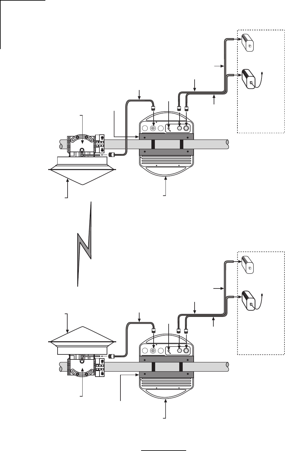
Information in this manual will familiarize you with all of these items. Figure 2.1 illustrates two
(2) Link AX terminals in a point-to-point configuration.
The Link AX is avaialble with two types of Outdoor Unit/Antenna configurations:
External Antennas : Requires the use of an external antenna (parabolic or flat panel
type), and the connection between ODU and antenna is per-
formed via the use of a 2-meter (6 feet) piece of RG8 type cable.
Typically this can be used for longer link distances up to 9 miles
(15 km).
Integral Antennas: A 9” flat panel antenna is integrated into the ODU housing, and
is internally connected. Typically this can be used for short link
distances up to 4 miles (6 km).
4
WaveNet Link AX Installation and Operations Manual
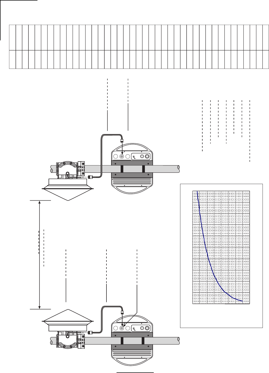
RSSI Test Point
1 Meter
ODU-Antenna
Interconnect
Cable
Data / Power Cable
RSSI Test Point
Data
21-56
VDC
Data
21-56
VDC
Link AX
5.3 GHz TX
Outdoor
Element
Indoor
Elements
Power Supply Link AX IDU
(optional)
Site A Site B
Antenna
5.3/5.8 GHz
Indoor
Elements
Antenna
5.3/5.8 GHz
Link AX
5.8 GHz TX
1 Meter
ODU-Antenna
Interconnect
Cable
Data / Power Cable
Power Supply
Antenna
Mount
Link AX IDU
(optional)
Antenna
Mount
Radio
Mount Kit
Radio
Mount Kit
WL292004
Figure 2.1 - Typical Deployment of a Link AX in a Point-to-Point External Antenna Configuration

5
WaveNet Link AX Installation and Operations Manual
2.2 Specifications
2.2.1 General Specifications
Frequency Range: 5.250 - 5.350 GHz and 5.725 - 5.825 GHz
RF Channel Bandwidth: 12 MHz
Channel Increments: 10.24 MHz
Radio Operation: Full duplex
Antenna Port Impedance: 50 ohms nominal
Ethernet Data Rate: 8 Mbps full duplex
2.2.2 ATM Interface
Type: ATM-25
Distance: 100 meters (330 ft) max
Termination: 100 ohm or 120 ohm RJ45 (user device per ATM 25.6
forum specification af-phy-0040.000)
ATM Traffic Parameters:
Parameter Description Min Typical Max Unit
PCR Peak Cell Rate 59259 Cps
SCR Sustained Cell Rate 15645 19200 19555 Cps
MBS Maximum Burst Size 3 Cell
MCR Minimum Cell Rate 0 Cps
2.2.3 Transmitter Specifications
Frequency Range: 5.250 - 5.350 GHz and 5.725 - 5.825 GHz
Channel Increments: 10.24 MHz
Modulation: BPSK
Power Output: 0, +4, +8, and +12 dBm
Transmit Duty Cycle: 100%
Emission Mask: Per FCC 15.407
Frequency Stability: ± 5 ppm
Data Rate: 8 Mbps
2.2.4 Receiver Specifications
Type: Coherent Detection
Sensitivity for 1x10⁻⁶ BER: -83 dBm
Receiver Overload for 1x10⁻⁶ BER -30 dBm
Maximum RF Input (no damage): -20 dBm
Data Rate: 8 Mbps
Channel Increments: 10.24 MHz

6
WaveNet Link AX Installation and Operations Manual
The 4-pin CircularMil power supply input connector pin assignments are shown in Table 2.2.
Note: The white lead of the power side of the Data/Power cable connects to Pin 1, thus it
should be connected to the negative lead of the power source. The red lead of the power
side of the Data/Power cable connects to Pin 2, thus it should be connected to the positive
lead of the power source.
2.2.7 Antennas
2.2.5 Digital Interface
ATM Interference on ODU
The 8-pin CircularMil (ATM interface/ODU status signals) connector pin assignments are
shown in Table 2.1.
2.2.6 Power Supply Input Connector on ODU
Table 2.1 - Connector Pin Assignment, ATM Connector on ODU
Table 2.2 - Connector Pin Assignment, Power Supply Input Connector on ODU
niPDAELNOITPIRCSED
1+XT+timsnarTriaPdetsiwT
2-XT-timsnarTriaPdetsiwT
3MLA/RWPUDInoDEL"mralAlacoL/rewoP"sevirdtahtlangiS
4ISSRhtgnertslangisgntacidniegatlovgolanA
5DNGAISSRrofdnuorG
6DNGDDELmralA/rewoProfdnuorG
7+XR+evieceRriaPdetsiwT
8-XR-evieceRriaPdetsiwT
300202LW
niPdaeLnoitcnuFroloC
1)-(tupnIevitageN.ylppusrewopfodaelevitagenotnoitcennoCetihW
2)+(tupnIevitisoP.ylppusrewopfodaelevitisopotnoitcennoCdeR
3desUtoN
4desUtoN
400202LW
Note: Pins 3-6 are used in conjunction with the Indoor Unit for test and maintenance purposes only.
Refer to DIP switch settings on page 34 for details. When connecting to a Network device, only pins
1,2,7, and 8 are used.

7
WaveNet Link AX Installation and Operations Manual
epyTrebmuNtraPdnarerutcafunaM
iBd81,deziraloPenlP,lenaPtalFdetargretnI"9 2.5-57.PFWsevaWoidaR
iBd5.71,deziraloPenalP,lenaPtalF"625-5.DPFDleirbaG
iBd32,deziraloPenalP,lenaPtalF"2125-1DPFDleirbaG
iBd3.32deziraloPenalP,hsidretemaid"21LN2.5-IPSsevaWoidaR
iBd5.72,deziraloPenalP,lenaPtalF"4225-2DPFDleirbaG
iBd1.82,deziraloPenalP,hsidretemaid"42IRA25-2PSSleirbaG
iBd1.82,deziraloPlauD,hsidretemaid"42IRA25-2DSSleirbaG
iBd5.33,deziraloPenalP,hsidretemaid"84*A25-4PSSleirbaG
iBd5.33,deziraloPlauD,hsidretemaid"84*A25-4DSSleirbaG
.tnailpmocCCFtoneradna,ylnoASUehtedistuoesuroferasannetnahsid"84ehT*
500202LW
Table 2.3 - Recommended Antennas
The antennas shown in Table 2.3 are recommended for use with Link AX. With the exception
of the 4’ dishes, all antennas have been tested with Link AX to verify compliance with applicable
FCC rules.
2.2.8 Power Requirements
Primary power supply
DC ±21 to ±56 V
AC 100 to 240V 50/60 Hz (with optional external power supply).
Power Consumption Maximum 17 Watts
2.2.9 Environmental Specifications
Outdoor Unit Operating Temperature Range: -30°C to +60°C
Storage Temperature Range: -40°C to +85°C
Altitude: 4,500 meters max.
Humidity: Outdoor, all-weather enclosure
2.2.10 Mechanical
Dimensions
ODU 310mm x 351mm x 73mm (HxWxD)
12.2” x 13.8” x 2.9”
Weight
ODU 5 kg
11 lbs

8
WaveNet Link AX Installation and Operations Manual
2.3 User Interfaces
The Link AX provides user interfaces for fused DC power connection, electrical grounding,
radio frequency (RF) antenna connection, ATM25 connection, configuration and RSSI output.
The following provides information on each interface.
Outdoor Unit
•Data/Power Cable - Siamesed CAT-5 ATM25 and power cables.
•RSSI - BNC type connector for RSSI measurement.
•Antenna (RF) Connector - N-type female connector used for connection with antenna.
Note: There is no N-Type RF connector used on ODUs with integral antennas.
•Main Power - The Link AX is designed to work from a power input of 21 to 56 VDC.
•Grounding Connector - The ODU is equipped with an M5 ground screw and associated
washers. This ground screw serves as the proper chassis-ground connection point for an
external ground source. The Link AX must be grounded in accordance with the electrical
codes, standards, and practices governing the local installation.
•Configuration Switch - Configuration of the Link AX is performed via a DIP switch on the
ODU. The 10-position DIP switch is accessible by removing the water-tight dust cap on
the ODU. Once exposed, each of the 10 switches can be manipulated using tool that is
provided with the mounting kit.
2.4 ODU Performance Monitoring
RSSI (Receive Signal Strength Indicator) - A voltage provided through a BNC connector on
the outside of the ODU. The RSSI port is used for antenna alignment during installation and
for periodic measurement of Receiver/Path performance. The RSSI voltage in relation to the
receive signal level ranges from -30 dBm to -90 dBm.

9
WaveNet Link AX Installation and Operations Manual
2.5 Theory of Operation
General Overview
The Link AX is a point to point Wireless ATM-25 Extender operating in the 5.3/5.7 GHz U-NII
band as authorized in rule sections 15.401 through 15.407. The unit is enclosed in a weather
proof outdoor enclosure and is intended to provide data links over distances up to 15 km. The
radio in the unit operates full duplex, transmitting and receiving data at the rate of 8.192 Mbps.
The radio is modulated using BPSK.
Circuit Description
The following circuit description is intended to explain the operation of the radio at the block
diagram level. This text is written with the idea that the reader has the block diagram readily
available, as it will aid in understanding the signal flow in the radio.
2.5.1 Link AX Transmitter
The physical interface to the radio consists of ATM-25 cells that are routed to ATM physical
interface (PHY) chip. The PHY chip stores the data cells, and then converts them into a
synchronous 8.448 Mbps data stream that is fed into the transmitter. To mark cell boundries,
a SYNC byte (01111110) is inserted at the beginning of every cell. Zero insertion circuitry,
inserts a zero after five consecutive ones, guaranteeing SYNC byte uniqueness while
transmiting the cell’s content.
The data is differentially encoded and scrambled before it is routed through the transmit
baseband filter to provide spectral shaping. The baseband filter is a five pole low pass filter.
After amplification, the baseband signal is fed to the modulator consisting of a doubly
balanced mixer. The modulator is running directly at the transmitter frequency of 5.775 GHz
± 50 MHz. The local oscillator signal of the mixer is supplied from the frequency synthesizer
section, with the frequency dependant on the RF channel selected.
From the output of the modulator, the signal is amplified and then passed through a 150 MHz
wide bandpass filter to remove any local oscillator products from the output spectrum. After
filtering, the signal is passed through a series of amplifier and attenuator stages that are used
to control the output power level. With a combination of fixed and variable attenuation the
output power can be set to one of four different levels to accommodate different antennas
used with the product.
The power setting is maintained by an active ALC circuit that samples the transmitter output
power and then adjusts the variable attenuator to keep the output power constant over the
operating temperature of the unit. The power level is controlled to within +1/-2 dB of the set
point.
Following the attenuators the signal is fed through additional amplification to bring the output
level to a maximum of +14 dBm at the output of power amplifier. A lowpass matching section
follows the power amplifier to aid in filtering harmonics of the signal. After passing through the
duplexer, the power level at the antenna port is a maximum of +12 dBm.
10
WaveNet Link AX Installation and Operations Manual
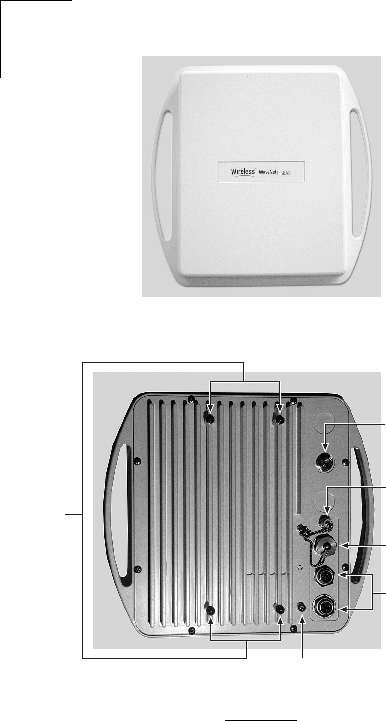
Figure 2.2a - Outdoor Unit, Front View, External Antenna
Figure 2.2b - Outdoor Unit, Back View, External Antenna
WL293001
DIP Switch Access
Antenna Connection
(N Type, Female)
ODU
Ground Connection
Mounting
Studs
WL292002
Receive Signal Strength
Indicator (RSSI) (BNC Type,
Female)
Siamesed Category 5
ATM and Power cables
connections
11
WaveNet Link AX Installation and Operations Manual
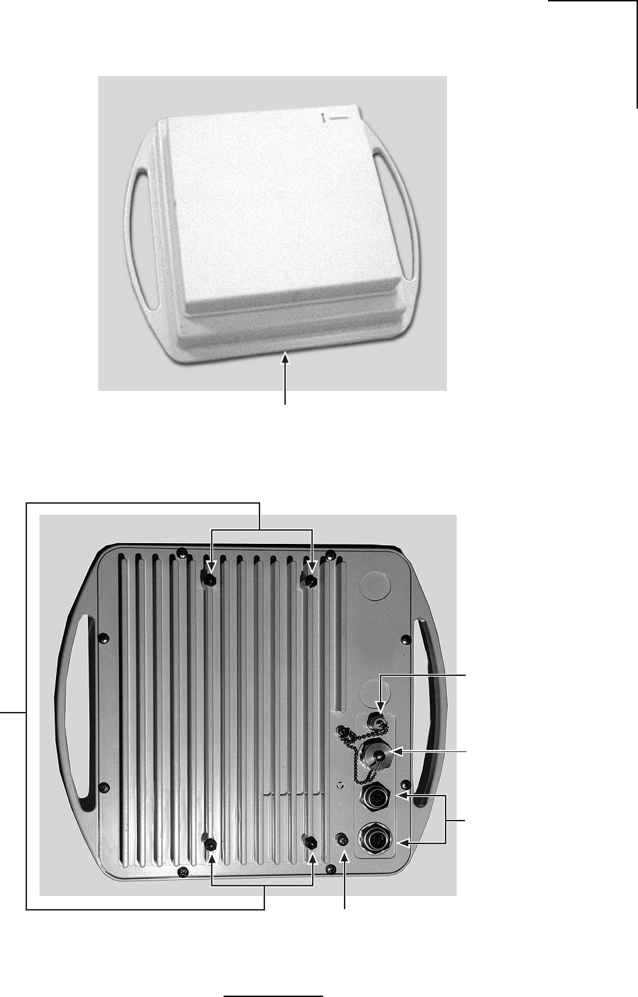
ODU
Ground Connection
Mounting
Studs
WL291003
Receive Signal
Strength Indicator
(RSSI) (BNC Type,
Female)
Siamesed Category 5
ATM and Power Cables
Connections
DIP Switch Access
Figure 2.2c - Outdoor Unit, Front View, Integral Antenna
Figure 2.2d - Outdoor Unit, Back View, Integral Antenna
Outdoor RF unit
with integral Antenna
WL241008

12
WaveNet Link AX Installation and Operations Manual
2.5.2 Link AX Receiver
The receiver in theLink AX is a conventional dual conversion design with IF frequencies of
474.88 MHz and 70 MHz.
From the receive port of the duplexer, the low level input signal is passed through a low noise
preamplifier that provides 25 dB of gain. Following the preamplifier the signal is passed
through a 200 MHz wide bandpass filter to provide image rejection for the first mixer.
The signal is then mixed with the first LO to convert the signal to 474.88 MHz. Following further
amplification the signal is passed through a five pole, 20 MHz wide bandpass filter. This filter
provides image filtering for the second mixer, and also helps attenuate signals on the adjacent
receive channels. After filtering, the signal is further amplified and then passed through a
variable attenuator stage before it is applied to the second mixer.
The output of the second mixer is at 70 MHz. The 70 MHz IF stages provide additional gain
along with two sections of variable attenuation for the AGC function. The primary adjacent
channel filtering is also at 70 MHz where the signal is passed through a 12 MHz wide SAW filter.
The combination of filters provide a minimum of 47 dB of attenuation at the adjacent receive
channels (±10.24 MHz).
At the end of the 70 MHz IF chain the signal is fed into a quadrature demodulator. The carrier
recovery loop consists of a four quadrant multiplier that multiplies I and Q baseband signals
to create an error voltage. This error voltage is then amplified and fed back to the 70 MHz VCO.
This forms a phase locked loop that is locked to the received carrier frequency.
The 70 MHz output is also fed into a wide band logarithmic amplifier that provides a DC voltage
output proportional to the 70 MHz signal strength. The DC voltage is then integrated and fed
back to the variable attenuator stages to form an AGC control loop. This control loop keeps
the signal level at the input to the demodulator chip constant over the entire operating range
of the receiver.
Data recovery from the I baseband signal begins by passing the I signal through a slicer. The
output of the slicer is a digital signal that contains both data and clocking information. A clock
recovery circuit recovers receive timing information that is needed to clock the data through
the descrambler, and differential decoder.
This 8.448 Mb bit stream is then converted into ATM cells. The SYNC bytes and the inserted
zeros are stripped form the cells prior to their delivery to the ATM25 PHY. This method provides
worst case cell rate of 15645 cells per second (cps) and typical cell rates of approximately
19200 cps.
13
WaveNet Link AX Installation and Operations Manual
2.5.3 Synthesizer
The FPGA provides four 22-bit streams in a serial format loaded to the synthesizer. This data
provides all of the possible frequencies at which the system can operate. Depending upon the
dip switch settings selected, the actual frequency being used is selected. When the reset
button is pressed, the FPGA will reload this data to the synthesizer.
Frequency Synthesis
The local oscillator frequencies used in the Link AX are all synthesized from a 19.2 MHz, ± 2.5
PPM reference oscillator. The overall frequency stability of the radio is ± 2.5 PPM, directly
reflecting the reference oscillator stability.
A dual frequency synthesizer chip is used to control both the first and second local oscillator
loops. This chip supports one high frequency oscillator, up to 1.5 GHz, and one lower
frequency oscillator to be used as a second LO.
The first local oscillator VCO operates at one half the transmitter output frequency, and
changes with the transmit channel selected. The first LO consists of a bipolar VCO operating
at 2.887 GHz ±25 MHz. The output of this VCO is buffered and then passed through a X2
prescaler chip before being fed back to the synthesizer chip. The phase comparison frequency
for the first LO is 320 kHz.
After amplification the 2.887 GHz signal is passed through a frequency doubler to create the
5.775 GHz signal that is applied to the mixer stages.
The second local oscillator consists of a VCO that is phase locked to 404.88 MHz. This auxiliary
synthesizer is operating with a phase comparison frequency of 240 kHz.
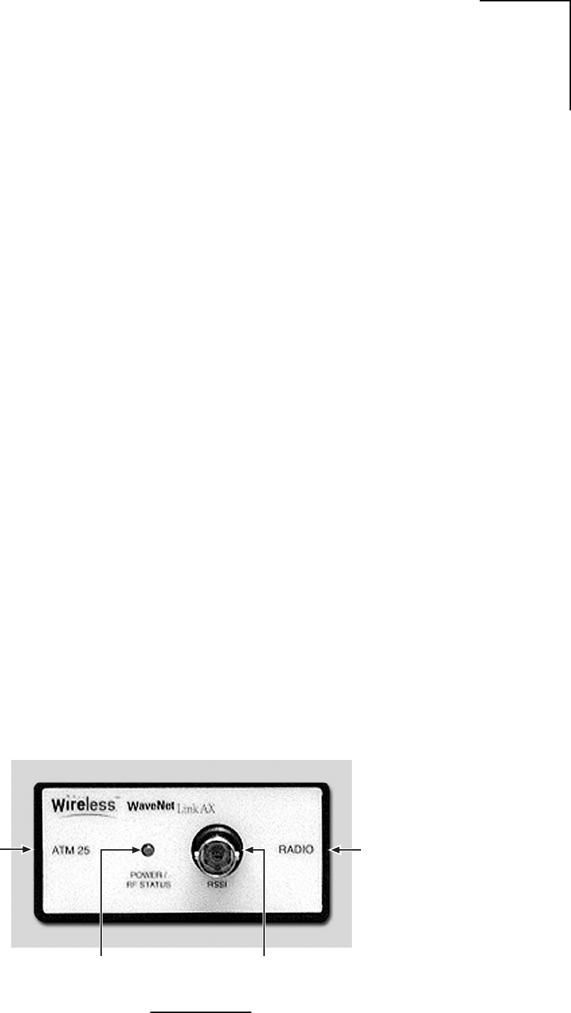
2.6 Indoor Unit
An optional Indoor Unit (IDU) can be used with the Link AX to provide diagnostics and
troubleshooting aid to maintenance personnel. The IDU contains a single LED that illuminates
with the presence of ATM25 data and power. Additionally a BNC connector is provided so that
maintenance personnel can view RSSI voltage inside the building. The IDU is NOT required
for operation of the Link AX radio system. Figure 2.3 shows the Link AX IDU.
Figure 2-3 Link AX Indoor Unit (IDU)
Radio Unit Connection
Measurement Port
RSSI (BNC Type Connector)
System power and
RF Status indicator
(Green LED)
ATM 25 interface
Connection
WL238005
14
WaveNet Link AX Installation and Operations Manual
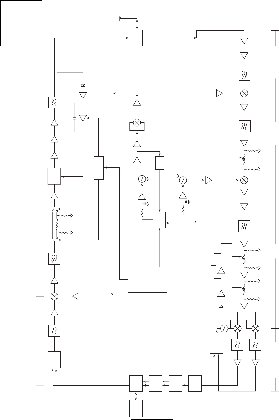
8.192 Mbit/sec,4.096 MHz 5.775 GHz +/- 50MHz
Baseband Filter Modulator Switchable
Attenuation
Scrambler
and Diff.
Encoder
Variable
Attenuation
Power Amp
ALC Circuitry
Power Control
Circuitry
Frequency
Doubler
Prescaler
2.887 GHz +/- 25MHz
VCO
Loop Filter
Dual
Frequency
Synthesizer
Loop Filter 404.88 MHz
VCO
FPGA
Power Programming
and Frequency
Programming
ATM 25
Interface Bridge
Chip
Descrambler
and
Decoding
Clock
Recovery
Circuitry
Data Slicer
Carrier
Recovery
Circuitry
70 MHz
VCO
AGC Control Circuitry
Baseband Filters
Quad
Demod.
Chip Variable Attenuator Variable Attenuator Variable Attenuator
8.192 Mbit/sec, 4.096 MHz 70 MHz 474.88 MHz 5.300 GHz +/- 50 MHz
Preamp
Duplexer
External
Antenna
Transmit Chain
Frequency Synthesis
Receive Chain
WL292005
Figure 2.4 - Link AX Block Diagram

15
WaveNet Link AX Installation and Operations Manual
3.0 Equipment Installation and Commissioning
3.1 Installation
The Link AX microwave radio system is intended for professional installation only. Prior to
installing the radio, both a site survey and path survey should be performed.
The site survey allows the installer to determine the best location for the radio, antenna, and
supporting structure, as well as determine antenna orientation, and cable route to the indoor
equipment. It is extremely important to mount the structure in such a manner that minimizes foot
traffic in front of the antenna (if installed on a roof, for example).
A path survey is completed to ensure that the radio will perform based on a given distance, and
in keeping with the EIRP limits, provides the installer with a target receive signal level which is
verified during antenna alignment. A sample calculation is provided in Figure 3.9.
The Link AX has been specifically designed for ease of installation. The following installation
instructions should be followed.
1. Plan the installation - Decide where each component of the Link AX will be placed prior
to commencement of any installation activity. Installation considerations for each compo-
nent in general are as follows:
a. Outdoor RF Unit - Mount as close as practical to the Antenna assembly. The maximum
distance is determined by the included interconnect cable. The installed cable is
2-meters in length. Determine pole mounting details for the Outdoor Unit and Antenna.
Table 3.1 identifies the maximum transmit power level setting that can be used with each
antenna while maintaining compliance with FCC EIRP regulations. Power levels are
referenced to the antenna port of the radio and are average power levels indicating what
would be measured using an average power meter. The FCC expresses limits as peak
power numbers. To convert from the average power numbers to peak power numbers,
add 1.8 dB to the average power numbers.

16
WaveNet Link AX Installation and Operations Manual
epyTannetnAN/PrerutcafunaM timsnarTmumixaM
)mBd(gnitteSrewoP
iBd5.71,deziraloPenalP,lenaPtalF,lanretxE"6 25-5.DPFDleirbaGiBd0
iBd81,deziraloPenalP,lenaPtalF,detargetnI"9 2.5-57.PFWsevaWoidaRiBd0
100003LW
Table 3.1 - Maximum Transmit Power Level Setting vs. Antenna Type (for compliance with FCC EIRP
limits) in the 5.3 GHz Band
If external antennas are utilized, and connected with the 2 meter cable mentioned in (a),
then factor in 2.6 dB for the loss in the coaxial cable when calculating EIRP figures.
If the product is being deployed in a country not governed by FCC regulations, the
installer should select a transmit power level setting appropriate for the antenna that is
deployed to maintain compliance with regulations employed by that country.
Refer to Table 2.6 for Configuration Switch setting information.
b. Antenna Unit - See Appendix B.
3.1.1 EIRP Calculations in the 5.3 GHz Band
The following is an excerpt from CFR 47 Part 15.407 (a)(1):
For the band 5.25-5.35 GHz, the peak transmit power over the frequency band of operation shall
not exceed the lesser of 250 mW or 11 dBm+10logB, where B is the 26-dB emission bandwidth
in MHz. In addition, the peak power spectral density shall not exceed 11 dBm in any 1-MHz
band. If transmitting antennas of directional gain greater than 6 dBi are used, both the peak
transmit power and the peak power spectral density shall be reduced by the amount in dB that
the directional gain of the antenna exceeds 6 dBi.
Based on the above rules, the Link AX (for the 5.3 GHz radio) must be configured by the installer
to operate using the conditions in Table 3.1 below. These values assume a nominal loss of 1.0
dB cable loss for the Wireless Inc. supplied RF cable (6 foot length) that connects the ODU to
the external antenna.

17
WaveNet Link AX Installation and Operations Manual
epyTannetnAN/PrerutcafunaM timsnarTmumixaM
)mBd(gnitteSrewoP
iBd5.71,deziraloPenalP,lenaPtalF,lanretxE"6 25-5.DPFDleirbaG21+
iBd81,deziraloPenalP,lenaPtalF,detargetnI"9 2.5-57.PFWsevaWoidaR21+
iBd32,deziraloPenalP,lenaPtalF,lanretxE"21 25-1DPFDleirbaG21+
iBd3.32,deziraloPenalP,cilobaraP,lanretxE"21 LN2.5-IPSsevawoidaR21+
iBd5.72,deziraloPenalP,lenaPtalF,lanretxE"42 25-2DPFDleirbaG21+
iBd1.82,deziraloPenalP,cilobaraP,lanretxE"42 IRA25-2PSSleirbaG21+
iBd1.82,deziraloPlauD,cilobaraP,lanretxE"42 IRA25-2DSSleirbaG21+
200003LW
3.1.2 EIRP Calculations in the 5.7 GHz Band
The following is an excerpt from CFR 47 Part 15.407 (a)(2):
For the band 5.725-5.825 GHz, the peak transmit power over the frequency band of operation
shall not exceed the lesser of 1 W or 17 dBm+10logB, where B is the 26-dB emission bandwith
in MHz. In addition, the peak power spectral density shall not exceed 17 dBm in any 1-MHz
band. If transmitting antennas of directional gain greater than 6 dBi are used, both the peak
transmit power and the peak power spectral density shall be reduced by the amount in dB that
the directional gain of the antenna exceeds 6 dBi. However, fixed point-to-point U-NII devices
operating in this band may employ transmitting antennas with directional gain up to 23 dBi
without any corresponding reduction in the transmitter peak output power or peak power
spectral density. For fixed point-to-point U-NII transmitters that employ a directional antenna
gain greater than 23 dBi, a 1 dB reduction in peak transmitter power and peak power spectral
density for each 1 dB of antenna gain in excess of 23 dBi would be required. Fixed, point-to-
point operations exclude the use of point-to-multipoint systems, omni directional applications,
and multiple collocated transmitters transmitting the same information. The operator of the U-
NII device, or if the equipment is professionally installed, the installer, is responsible for ensuring
that systems employing high gain directional antennas are used exclusively for fixed, point-to-
point operations.
Based on the above rules, the Link AX (for the 5.7 GHz radio) must be configured by the installer
to operate using the conditions in Table 3.2 below. These values assume a nominal loss of 1.0
dB cable loss for the Wireless Inc. supplied RF cable (6 foot length) that connects the ODU to
the external antenna.
Table 3.2 - Maximum Transmit Power Level Setting vs. Antenna Type (for compliance with FCC EIRP
limits) in the 5.7 GHz Band, Orignial and July 31, 1998 rules

18
WaveNet Link AX Installation and Operations Manual
ytQnoitpircseD
1XAkniL
1srenetsafdetaicossadnatekcarBdetnuoMtlitro,llaW,eloP
1elbaCrewoP/MTAdesemaiS
1annetnAlanretxE(ylbmessAelbaClaixaoCelaM-NotelaM-N
)ylnO
1retpadArewoPCDotCA
1)ylnosmetsySannetnAlanretxE(annetnA
210202LW
2. Inventory your equipment and installation materials.
To install one (1) terminal you should have the items shown in Table 3.3.
3. The following tools should be on hand:
Table 3.4 - Inventory of Equipment and Installation Materials
looTesopruP
rettuC/reppirtSeriW sesoprupgnittucdnagnippirtseriwlareneG
efinKytilitU noitareperpelbaclareneG
deppiuqe)MMD(retemtloVlatigiDdleH-dnaH
gulpananaB-lauDotCNBseborpdradnatshtiw
annetna(srotcennocCNBhtiwelbacxaoc'3dna
)tnemngila
ytiunitnoc,ytiralop,edutingamsmrifnoC
sehcnerWelbatsujdA mm22otputinUroodtuO,gnitnuoMannetnA
revirdwercSspillihP2# gnidnuorGtinUroodtuO
revirdwercSedalBtalF2#gnitnuoMannetnA
looTpmirCguLedapS noitareperPdnuorGUDO
rotcennoCpmirC54JRnoitareperPelbaC
100492LW
Table 3.3 - List of Tools
3.2 ATM25 Data Connector
The ATM25 connections are made to the data side of the power/data cable assembly, normally
it is supplied with an RJ45 connector. Pin-Outs for the RJ45 cable are as follows:
19
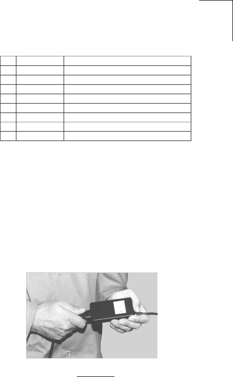
WaveNet Link AX Installation and Operations Manual
WL202013
Figure 3.1- Power Cord Connection
3.3 Connect the Power Supply
3.3.1 DC Power Supply
niPDAELNOITPIRCSED
1+XT+timsnarTriaPdetsiwT
2-XT-timsnarTriaPdetsiwT
3MLA/RWPUDInoDEL"mralAlacoL/rewoP"sevirdtahtlangiS
4ISSRhtgnertslangisgntacidniegatlovgolanA
5DNGAISSRrofdnuorG
6DNGDDELmralA/rewoProfdnuorG
7+XR+evieceRriaPdetsiwT
8-XR-evieceRriaPdetsiwT
300202LW
Table 3.5 - Connector Pin Assignment, ATM Connector on ODU
The white lead of the power side of the Data/Power cable connects to Pin 1, thus it should be
connected to the negative lead of the power source. The red lead of the power side of the Data/
Power cable connects to Pin 2, thus it should be connected to the positive lead of the power
source.
3.3.2 Optional AC Power Supply
The AC-DC power supply is connected to an AC outlet by means of an IEC type power cord.
Connect the power cord to the supply as shown in Figure 3.1. The output of the supply should
be connected to the power side of the Data/Power cable using guidelines shown in Table 2.2.
3.4 Outdoor RF Unit Installation
General
The outdoor unit is installed by means of a pole mount adaptor bracket (wall mount optional)
20
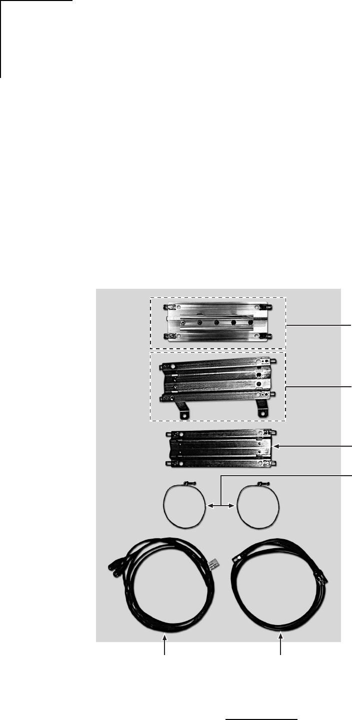
WaveNet Link AX Installation and Operations Manual
WL293003
Siamesed Category 3
Ethernet and Power Cable
for IDU to ODU Interconnection
N-Male to N-Male
ODU to Antenna
Coaxial Cable Assembly
Pole Mount
Bracket Fasteners
Wall Mount Bracket
(Optional)
Pole Mount Bracket
Tilt Mounting Bracket
(Optional)
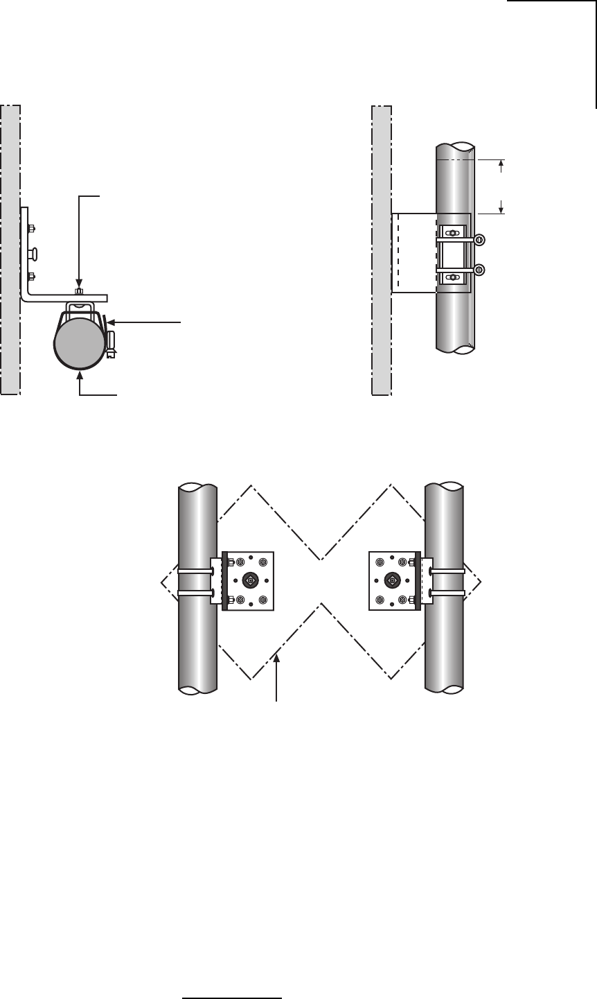
that is secured to the pole using two metal hose type clamps. Figure 3.2 shows the hardware
provided to mount the Outdoor RF Unit.
1. Ensure DIP
2. Install the outdoor unit pole mount adaptor bracket using the supplied metal hose type
clamps. See Figure 3.3.
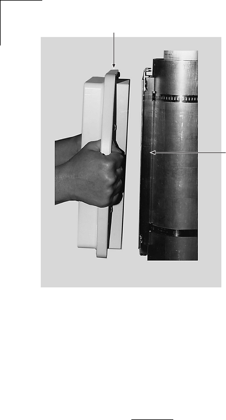
3. Align the four mounting studs on the outdoor unit with the bracket holes (See Figure 3.4)
and secure to the bracket by pushing down the latches as shown in Figures 3.5a and 3.5b.
4. Connect the Siamesed Category 5 ATM/Power cable, the N-type antenna, the coaxial
cable, and the ground connections as shown in Figures 3.6a and 3.6b.
3.7.2 Aligning the Link AX System Antennas
With the Link AX at each site properly configured for operation, antenna alignment must be
performed at both sites. Proper antenna alignment is crucial to the proper operation of an Link
Figure 3.2 - Outdoor Unit Mounting Hardware
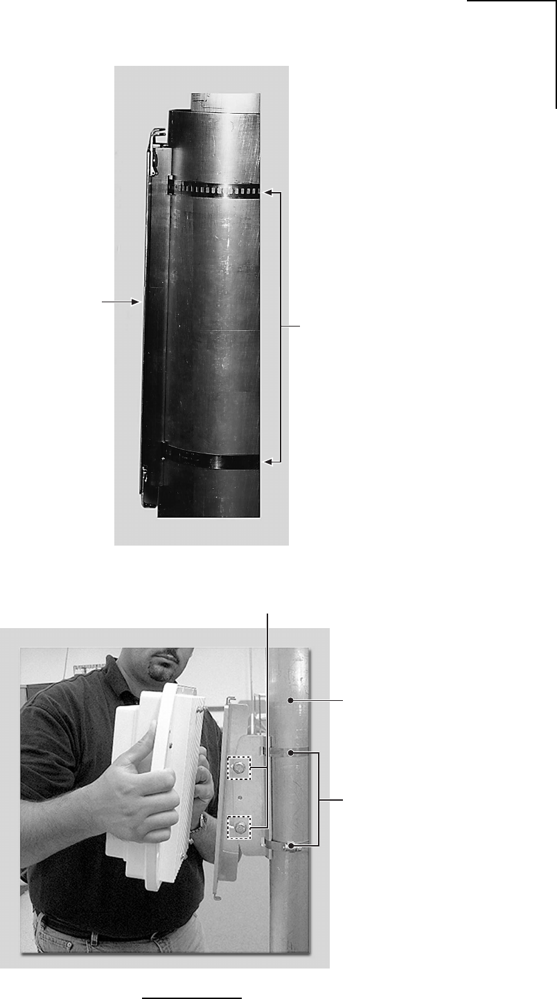
21
WaveNet Link AX Installation and Operations Manual
Pole Mount
Bracket
Hose
Clamps
WL202015
Figure 3.3 - Attaching the Pole or Tilt Mount Adaptor Bracket
WI291002
Pole
Hose
Clamps
Vertical
Adjustment
Bolts
22
WaveNet Link AX Installation and Operations Manual
Figure 3.4 - Mounting the Outdoor RF Unit to the Bracket
Pole Mount
Bracket
Outdoor Unit
WL202016
23
WaveNet Link AX Installation and Operations Manual
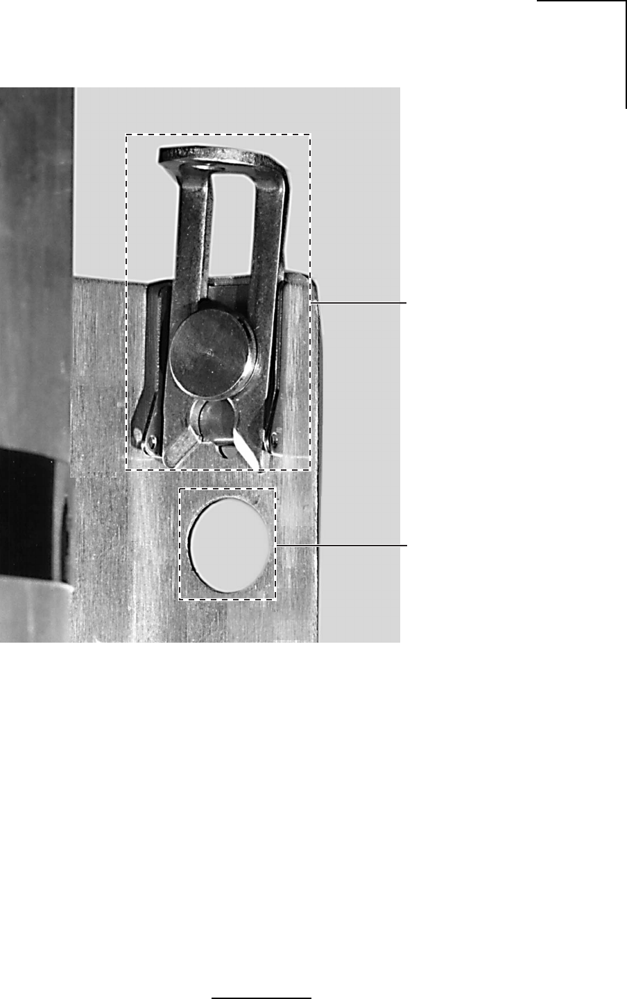
Detail of Latch Mechanism
for Securing the Outdoor Unit
to the Pole Mount
(4 Places on Bracket)
Outdoor Unit
Mounting Studs
placed through
this hole
WL202017
Figure 3.5a - Mounting Bracket Latch and Stud Mount Detail
24
WaveNet Link AX Installation and Operations Manual
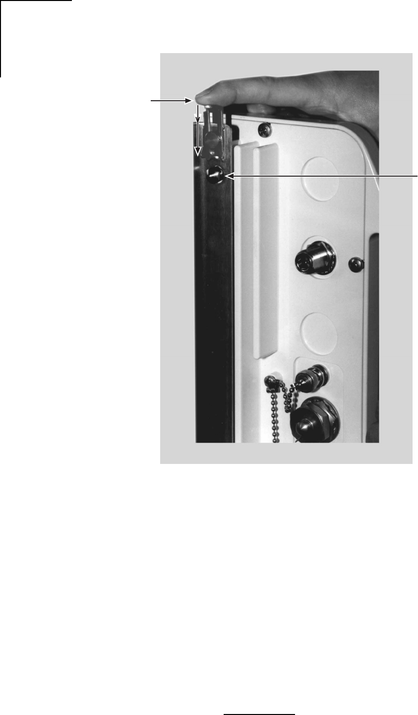
Mounting
Studs x 4
Press locking latches
down to secure the ODU
to the pole mount bracket
WL202018
Figure 3.5b - Locking the Mounting Hardware
25
WaveNet Link AX Installation and Operations Manual
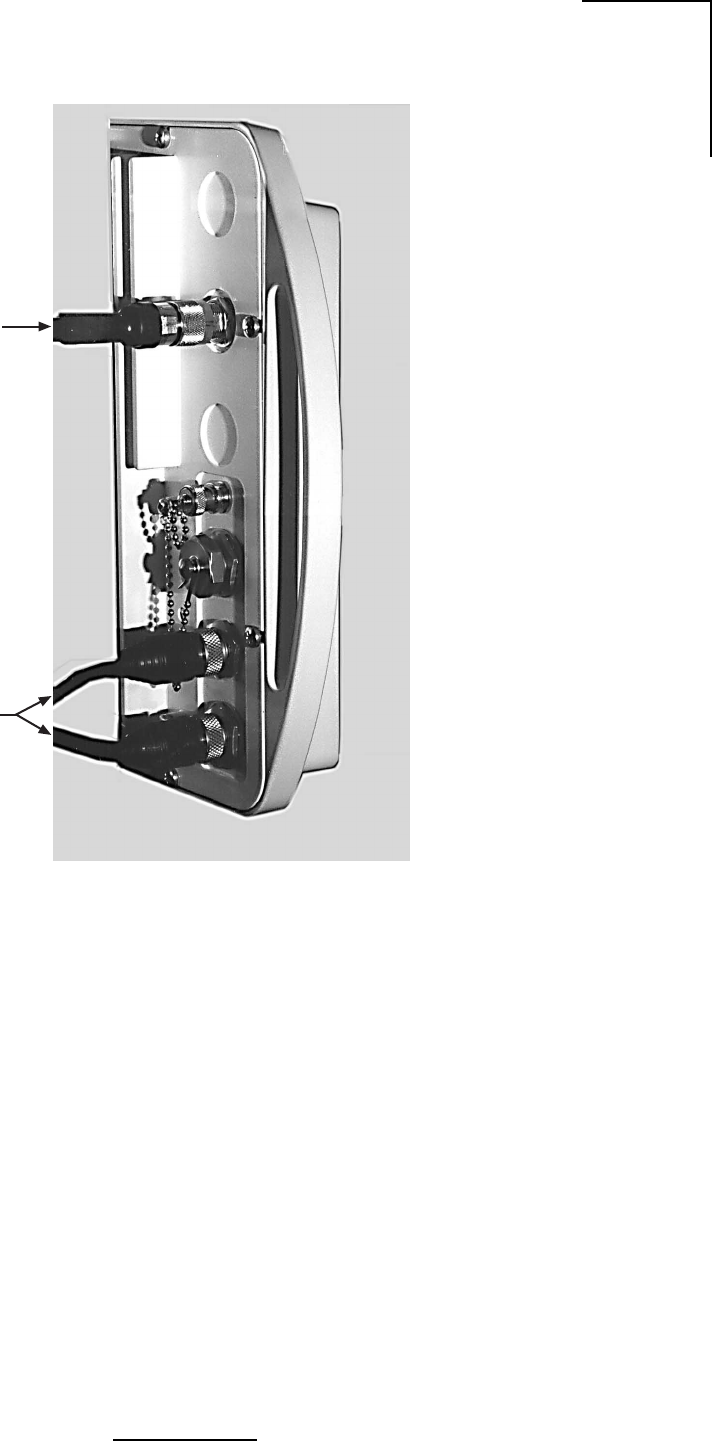
WL292003
50 Ohm
Antenna
Cable
Siamesed Category 5
Ethernet / Power Cable
Figure 3.6a - N-Type Antenna and Siamesed Ethernet/Power Connections
26
WaveNet Link AX Installation and Operations Manual
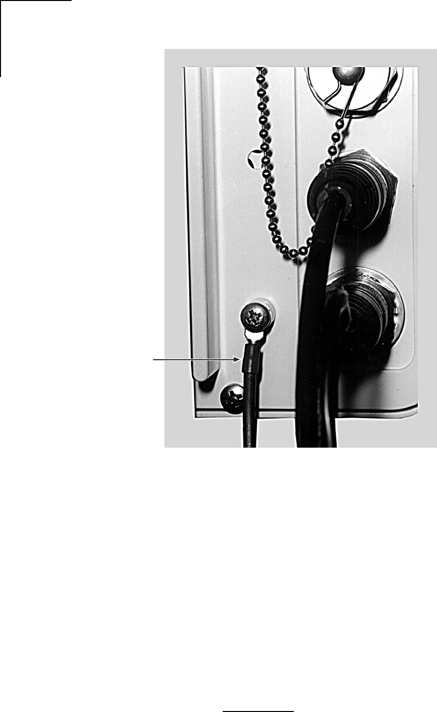
Ground Cable
(not supplied)
WL202020
Figure 3.6b - Ground Connection
27
WaveNet Link AX Installation and Operations Manual
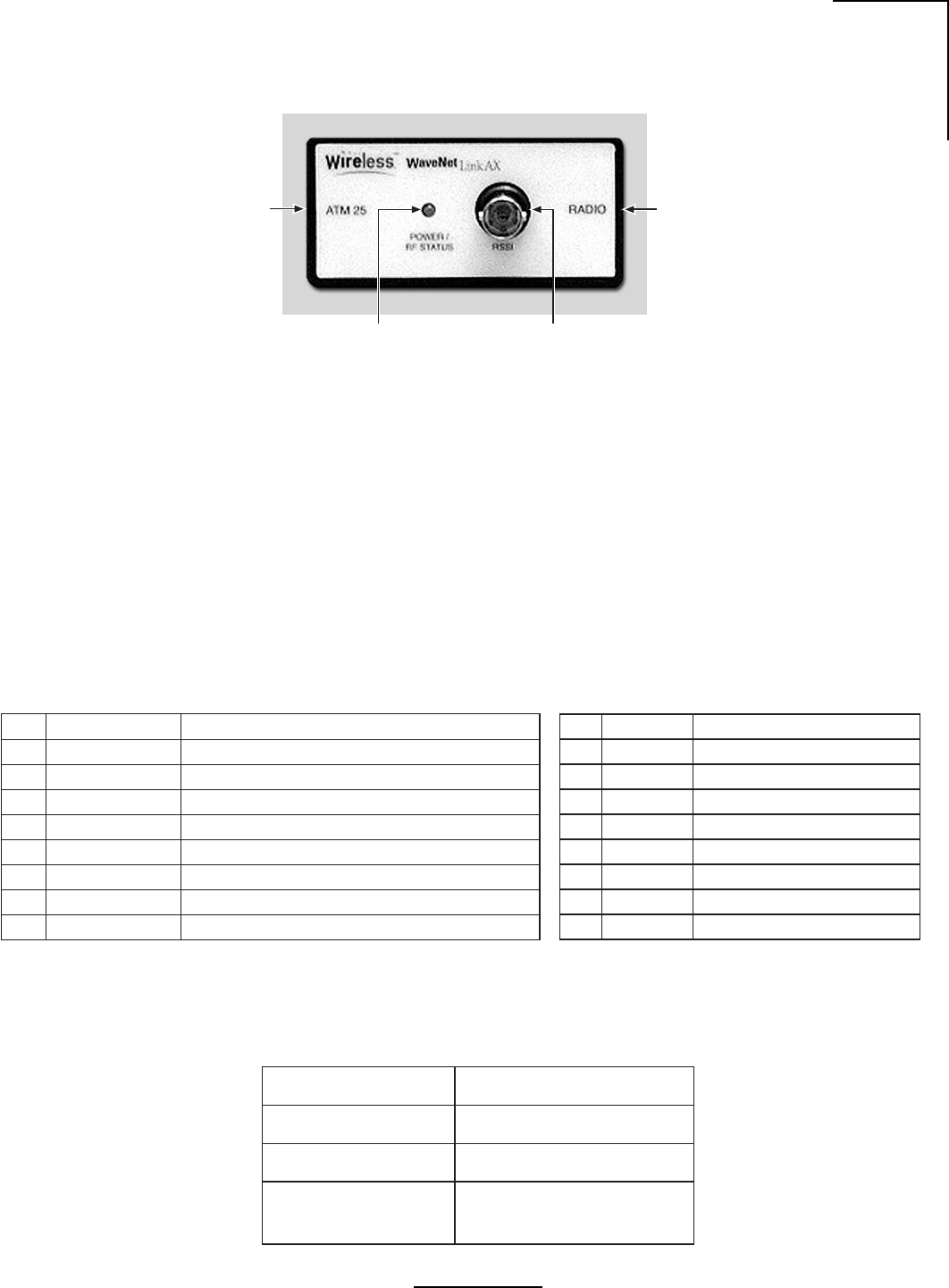
Figure 3.7 - Link AX Indoor Unit (IDU)
Radio Unit Connection
Measurement Port
RSSI (BNC Type Connector)
System power and
RF Status indicator
(Green LED)
ATM 25 interface
Connection
WL238005
3.5 Indoor Unit
Table 3.6a and Table 3.6b - Connector Pin Assignment, ATM Connector on ODU
niPDAELNOITPIRCSED
1+XT+timsnarTriaPdetsiwT
2-XT-timsnarTriaPdetsiwT
3MLA/RWPUDInoDEL"mralAlacoL/rewoP"sevirdtahtlangiS
4ISSRhtgnertslangisgntacidniegatlovgolanA
5DNGAISSRrofdnuorG
6DNGDDELmralA/rewoProfdnuorG
7+XR+evieceRriaPdetsiwT
8-XR-evieceRriaPdetsiwT
300202LW
An optional Indoor Unit (IDU) can be used with the Link AX to provide diagnostics and
troubleshooting aid to maintenance personnel. The IDU contains a single LED that illuminates
with the presence of ATM25 data and power. Additionally a BNC connector is provided so that
maintenance personnel can view RSSI voltage inside the building. The IDU is NOT required
for operation of the Link AX radio system. Figure3.7 shows the Link AX IDU.
Tables 3.6a and 3.6b show the connector Pin Assignment for the Radio Port and the ATM25
Port.
niPDAELNOITPIRCSED
1+XT+timsnarTriaPdetsiwT
2-XT-riaPdetsiwT
3desUtoN
4desUtoN
5desUtoN
6desUtoN
7+XR+evieceRriaPdetsiwT
8-XR-evieceRriaPdetsiwT
400392LW
DELsutatSFR/rewoPnoitpircseD
)dilos(NOsmralaoN,yakosiUDOotrewoP
FFOUDOotrewopoN
)gniknilB(NO
noitidnocmralalacoL-
tupniMTAfossoL-
)REBknilhgih(srorreMTA-
500392LW
Table 3.6c - IDU LED Status
Radio Port ATM25 Port
Table 3.6c explains the IDU LED staus.

28
WaveNet Link AX Installation and Operations Manual
hctiwSnoitcnuF
3dna,2,1
noitceleSlennahCdnaycneuqerF
1hctiwS2hctiwS3hctiwS.hC)zHG(riaPycneuqerF
nOnOnO1 08062.586537.5
ffOnOnO2 40172.529547.5
nOffOnO3 82182.561657.5
ffOffOnO4 25192.504667.5
nOnOffO5 67103.546677.5
ffOnOffO6 00213.588687.5
nOffOffO7 42223.521797.5
ffOffOffO8 84233.563708.5
5dna4
lortnoCrewoPtimsnarT
4hctiwS5hctiwSzHG7.5/zHG3.5troPannetnAtarewoPxT
ffOffOmBd0
ffOnOmBd4+
nOffOmBd8+
nOnOmBd21+
6desUtoN
01dna,9,8,7
elbasiDUDI
UDIotdetcennoceblliwUDO=nO
UDIotdetcennocebTONlliwUDO=ffO
:etoN siti,tnempiuqelanretxeotegamadlaitnetoptneverpotredronI
ottesera01hguorht7hctiwstahtevitarepmi ffO .noitisop
:etoN ninwohserasgnitteshctiwsPIDtluafedyrotcaF dlob .ecafepyt
800202LW
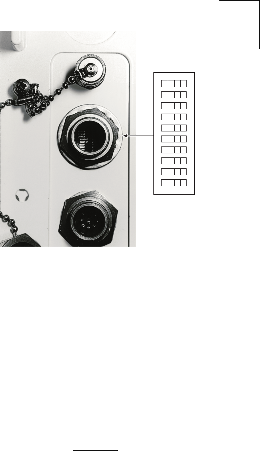
3.6 DIP Switch Function and Configuration
Refer to Table 3.7 below. Switches 1, 2 and 3 control Frequency and Channel selection.
Switches 4 and 5 are used for Transmit Power control. Switch 6 is not used. Switches 7-10 are
used only when the optional Indoor Unit (IDU) is placed in-line between the ODU and the ATM
terminating device.
Note: After the last switch has been set, the radio will learn its new configuration in five
seconds. There is no requirement to power cycle the radio after dip switches are changed.
Table 3.7 - DIP Switch Configuration
29
WaveNet Link AX Installation and Operations Manual
WL202026
ON CTS
10987654321
Figure 3.8 - DIP Switch Access and Configuration Information

30
WaveNet Link AX Installation and Operations Manual
tsilkcehCnoitallatsnI
?yltcerrocdetcennocdnadedivorpegatlovreporpsI
)lanimretrepwardlanimonsttaW61,CDV65-12(
?dednuorgylreporpUDOehtsI
?UDOehtotdetcennocylreporpannetnaehtsI
dnaecalpni)52-MTA(noitcennocatadehtsI
?tcerroc
ylreporp)eloP,tsaM(erutcurtsgnitnuomehtsI
?dednuorg
htob(enalpemasehtnidetneirosannetnAehterA
?)latnozirohhtobro,lacitrev
etomerfohtumizalarenegnidetniopannetnayfireV
.dne
nosrotcennocepyT-NfolaesrehtaewreporpyfireV
.annetnadnaUDO
950312LW
3.7 Commissioning
1. Visually verify that the Link AX is properly mounted
2. Verify that the DC power input to the Link AX is on.
Refer to Table 3.8.
3.7.1 Configuring Link AX System Antennas
External Antennas:
The antennas used on an Link AX radio system are generally configurated for either vertical or
horizontal polarization. It is extremely important to verify that both antennas are configured for
the same polarization, and that the appropriate antenna polarization has been selected for the
specific radio link.
Integral Antennas:
The integral antennas are set at the factory for either vertical or horizontal polarization, and
cannot be changed in the field. If a different polarization is required, contact the distributor or
Wireless, Inc. for an exchange or replacement. As with external antennas, the installer must
verify that both ends of the link are configured for the same polarization.
Failure to observe same polarity on both ends of the link will result in at least a 25 to 30 dBi
reduction in receive signal level.
Table 3.8 - Installation Checklist

31
WaveNet Link AX Installation and Operations Manual
AX radio system, and should only be accomplished by experienced professionals.
The Link AX is equipped with a ODU mounted BNC-(f) RSSI connector to which an analog or
digital voltmeter can be connected. The voltage range at the test point, between the center
conductor of the connector and ground, varies from approximately two VDC to four VDC,
serving as a receive signal strength indicator (RSSI). The stronger the receive signal, the higher
the RSSI voltage. Refer to Table 3.5.
Emanating from a microwave antenna is a main beam (or lobe) of RF energy, surrounded by
RF side lobes. The beamwidth of the main beam varies with the size and type of antenna, as
well as the specific frequency of the RF signal, and is generally defined by the nominal total width
of the main beam at the half-power (-3 dB) points. Side lobes surround the main beam at specific
angle distances, and will be lower in power than the main beam.
When aligning an antenna system, it is extremely important to verify that the antennas are both
aligned on the main beam, not on a side lobe. Referencing Table 3.6, the first side lobe will
generally be located at an angle slightly less than twice the antenna beamwidth.
Following the course alignment of an antenna system, a common practice when performing a
fine alignment is to slowly swing each antenna (one at a time!) in both vertical (elevation) and
horizontal (azimuth) planes to verify that the main beam and first side lobe can be accurately
identified. This insures that accurate alignment of the antenna system on the main beam has
been accomplished.
Each Link AX is shipped with an RSSI test sheet, showing the relationship between the receive
signal strength level (in dBm) and the RSSI level (in VDC). These RSSI test sheets are often
referred to as AGC Curves. The RSSI test sheets can be used to verify that the calculated
receive signal levels match up with the actual receive signal levels. Substantial differences
between calculated and actual levels could point to transmission system problems, side lobe
alignment, path obstructions, etc.
32
WaveNet Link AX Installation and Operations Manual
elytSdnaretemaiDannetnA)iBd(niaG)seerged(htdiwmaeBBd3
lenaptalf"65.710.91
lenaptalf"21324.9
cilobaraP"213.328.11
cilobarap"421.821.6
lenaptalf"425.727.4
*cilobarap"842.031.3
.tnailpmocCCFtoneradna,ylnoASUehtedistuoesurofsiannetnahsid84ehT*
320202LW
Table 3.10 - Approximation Table
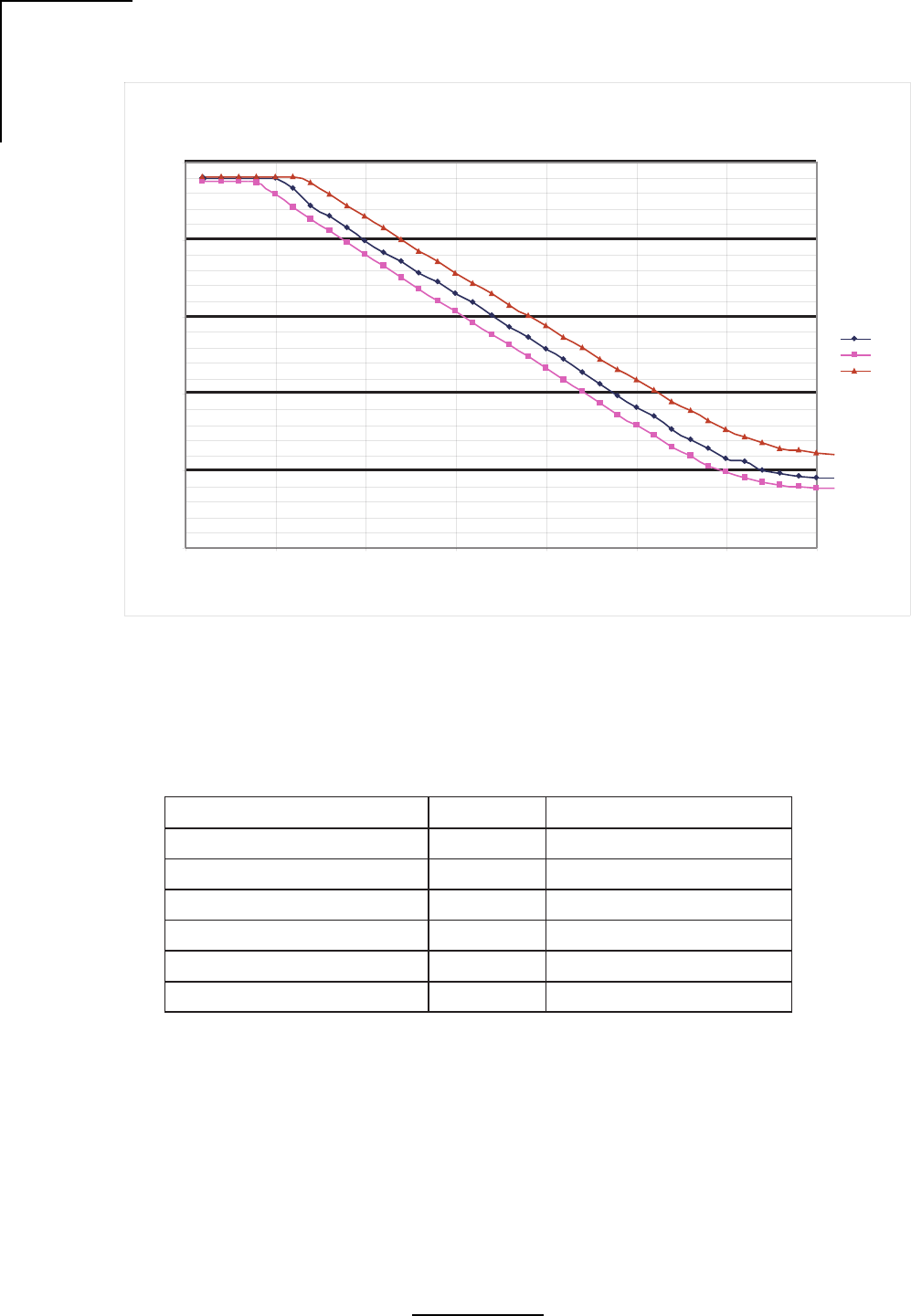
Table 3.9 - RSSI Voltage vs. Receive Signal Level
RSSI versus RSL Typical
0.00
1.00
2.00
3.00
4.00
5.00
-90-80-70-60-50-40-30-20
Receiver Signal Level (dBm)
25 C
65 C
-35 C
RSSI (V)
WL205001

33
WaveNet Link AX Installation and Operations Manual
3.7.3 Verifying Antenna Alignment
Wireless Inc. recommends that the installer verify the alignment of the antennas by performing
a simple calculation. Verifying proper antenna alignment is critical to the installation of the
equipment, as it ensures that the desired signal is being received, as well as ensures that the
transmitter is sending data to the desired remote location. A sample calculation is provided
below:
1) Determine Tx Power Outpour +4 dBm
2) Determine coax cable loss (if external antenna) -2.6 dB
3) Determine Tx Antenna Size and Gain (from table 3.6) +23 dBi
1’ parabolic
4) Determine Free Space Loss
Distance is 3 miles = 20log(3) +111.72 -121.3 dB
5) Determine Rx Antenna Size and Gain (from table 3.6) +23 dBi
1’ parabolic
6) Determine coax cable loss (if external antenna) -2.6 dB
7) Add Gains and Losses to determine RSL -76.5 dBm
Referring to table 3.9, a Receive Signal Level of -76.5 dBm is roughly equivalent to 1.3V. The
installer should refer to the RSSI test sheet supplied with each ODU to determine the correct
voltage for the ODU.
34
WaveNet Link AX Installation and Operations Manual
Local Remote
Antenna Gain dBi
Cable loss = 2.6 dB
TX output dB
Cable loss = 2.6 dB
Calculated RSL dB
Free space loss dB
Distance miles
5.7 GHz Free Space Loss vs. Distance
95.0 dB
100.0 dB
105.0 dB
110.0 dB
115.0 dB
120.0 dB
125.0 dB
130.0 dB
135.0 dB
0.0 mi 1.0 mi 2.0 mi 3.0 mi 4.0 mi 5.0 mi 6.0 mi 7.0 mi 8.0 mi 9.0 mi 10.0 mi
Distance
Free Space Loss
Local Tx RF dBm
- Local Cable loss dB
+ Local Antenna Gain dBi
- Free Space loss dB
+ Remote Antenna Gain dBi
- Remote Cable loss dB
RSL= dB
WL293002
selimLSF
im52.0Bd86.99
im05.0Bd07.501
im57.0Bd22.901
im00.1Bd27.111
im52.1Bd66.311
im05.1Bd42.511
im57.1Bd85.611
im00.2Bd47.711
im52.2Bd67.811
im05.2Bd96.911
im57.2Bd05.021
im00.3Bd62.121
im52.3Bd69.121
im05.3Bd06.221
im57.3Bd02.321
im00.4Bd67.321
im52.4Bd92.421
im05.4Bd87.421
im57.4Bd52.521
im00.5Bd07.521
im52.5Bd21.621
im05.5Bd25.621
im57.5Bd19.621
im00.6Bd82.721
im52.6Bd46.721
im05.6Bd89.721
im57.6Bd03.821
im00.7Bd26.821
im52.7Bd29.821
im05.7Bd22.921
im57.7Bd05.921
im00.8Bd87.921
im52.8Bd50.031
im05.8Bd13.031
im57.8Bd65.031
im00.9Bd08.031
im52.9Bd40.131
im05.9Bd72.131
im57.9Bd05.131
im00.01Bd27.131
300262LW
Figure 3.9 - Receive Signal Level

35
Wavenet Link AX Installation and Operations Manual
4.0 Antenna Installation
The following section describes the installation details of various antennas offered in a pictorial
format.
4.1 Equipment Inventory List
Table 4.1 - Inventory of Equipment and Installation Materials
metInoitpircseD rebmuNtraPytQ
1)dnaBwoL(tinUXTzHG3.5 1
annetnAlanretxE)a 100-070001
ytiraloPlacitreV,annetnAlanretnI)b 100-680001
ytiraloPlatnoziroH,annetnAlargetnI)c 100-180001
2)dnaBhgiH(tinUXTzHG7.5 1
annetnAlanretxE)a 100-570001
ytiraloPlacitreV,annetnAlargetnI)b 100-780001
ytiraloPlatnoziroH,annetnAlargetnI)c 100-280001
3annetnA 2
iBd12,lenaPtalF)mc03("21)a 101-215574-190
iBd32,cilobaraP)mc03("21)b 540001CA
iBd82,cilobaraP)mc06("42)c 101-425554-190
4tiKgnitnuoM 2
tiKtnuoMeloP)a eloP77000TIK
tiKtnuoMllaW)b llaW710000TIK
5)ylnoesUroodnI,lanoitpo(rotcetorPNAL 100-8800012
6retem1,elbaClaixaoC 800001CA2
7elbaCrewoPataD 2
)'21(m4,rewoPdnaataD)obmoc(esemaiS)a 3400001CA
)'57(m52,rewoPdnaataD)obmoc(esemaiS)b 0400001CA
)'051(m05,rewoPdnaataD)obmoc(esemaiS)c 1400001CA
)'003(m001,rewoPdnaataD)obmoc(esemaiS)d 2400001CA
retaepeRkcaB-ot-kcaB)'3(m1,elbaCretaepeR)e 100-151001
3eton
retaepeRkcaB-ot-kcaB)'3(m1,elbaCretaepeR)f 200-151001
3eton
noitacilppAretaepeR,m3,elbaCrewoP)g 100-251001
noitacilppAretaepeR,m52,elbaCrewoP)h 200-251001
noitacilppAretaepeR,m05,elbaCrewoP)j 300-251001
noitacilppAretaepeR,m001,elbaCrewoP)k 400-251001
mX,elbaCecafretnItroPratS)l .D.B.T
mX,elbaCecafretnIteNmaertS)m .D.B.T
8CDV42otzH06/05CAV022/011,ylppuSrewoP 2
gulPnaciremAhtroN 1-4400001CA
gulPnaeporuE 2-4400001CA
:setoN
kniLfoknilenoetelpmocotderiuqererasmetilla,lanoitposadetonesiwrehtosselnU)1
.oidarXA
,ytiralopemasehtevahtsumknilehtfosdnehtob,deredroerasannetnalargetnifI)2
.latnozirohhtobrolacitrevhtob.e.i
etisretaeperehttaderiuqersielbacretaepeRenoylno,snoitacilpparetaeperroF)3
.)k-g7smeti(etisretaeperehttaderiuqereraselbacrewopowT.)f7roe7smeti(
300272LW
36
Wavenet Link AX Installation and Operations Manual
4.2 Antenna Install and Rough Alignment
Read the instructions completely before assembling or installing the antenna. This installation
can be dangerous and requires qualified personnel familiar with microwave assembly and
installation.
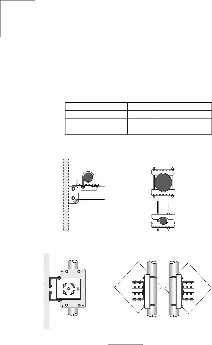
4.2.1 Flat Panel Type Antennas, 6”, 12”, and 24”
Table 4.2 reflects the different flat panel antenna dimensions. Assemble the panel mount
according to Figure 4.1. Orient Antenna using instructions supplied with the antenna. Antenna
models used with this mount may be circular, square or diamond shaped. To change the offset
of the antenna, unbolt the mount from the antenna, invert the mount and reattach to the antenna.
Table 4.2 - Approximation Table of Flat Panel Antennas
elytSdnaretemaiDannetnA)iBd(niaG)seerged(htdiwmaeBBd3
lenaptalf"65.710.91
lenaptalf"21324.9
lenaptalf"425.727.4
100482LW
Figure 4.1 - Antenna Mount
2 3/8” (60mm)
DIA Mast
(2) 1/4” U-Bolt w/
Washer, Lockwashers
and Nuts
Azimuth Adjustment
Slots
Top View Optional Mast Clamp Kit
for 1.9” (48mm) DIA thru
4.5” (114mm) DIA Masts
Side View
Elevation
Adjustment
Slots
Rear View
Offset Left Rear View
Offset Right
WL202056
37
Wavenet Link AX Installation and Operations Manual
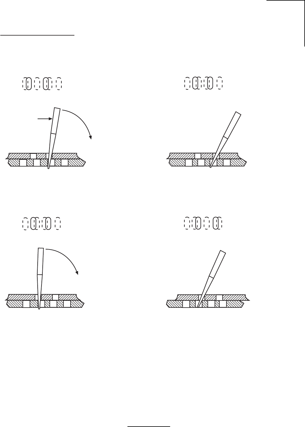
Azimuth and Elevation Panning
Loosen the Azimuth or Elevation Locking
Hardware while maintaining sufficient
friction to prevent unwanted slippage.
1)
Sectional View Looking at Edge of Slots
View Looking Down on Slots
Insert flat blade screw driver into slot
“B” and pry in direction of arrow or into
slot “A” and pry in opposite direction.
2)
Screw Driver
Flat Blade
AB
Stop prying approximately at position
shown as new overlapping slot in bottom
plate becomes sufficiently visible when
viewed through slot “A”.
3)
AB
Stop prying approximately at position
shown as new slot in bottom plate
becomes sufficiently visible when
viewed through slot “B”. Continue
alternating slots and prying in either
direction until desired alignment is
obtained. Lock down hardware securely
before leaving site.
5)
AB
Insert screw driver into slot “A” and pry
in direction of arrow.
4)
AB
WL266002
Figure 4.2 - Adjustable Panel Antenna Mount
38
Wavenet Link AX Installation and Operations Manual
Polarization arrow,
horizontal polarity
shown
Location of open drain holes
in square or rectangular
Panel Antennas
Location of open Drain Hole in
round or diamond shaped
Antennas
After orienting the Antenna to its proper polarization,
plug all of the Drain Holes, except for lower most Drain
Hole(s), by inserting Screws with O-rings.
D
ra
i
n
H
o
l
es
Each Panel Antenna has (4) Drain Holes located on
the back of the Antenna.
Rear View
Left Offset
Horizontal Polarization: Arrow sticker
should be pointed in a horizontal direction.
Vertical Polarization: Arrow sticker
should be pointed in a vertical direction.
A
n
t
enna
P
o
l
ar
i
za
ti
on
Assemble antenna to mount using four
sets of Nuts and Washers after desired
polarization is selected.
Important
After cable connection is completed,
wrap connection with Butyl or other
waterproof tape, supplied by customer.
WL264002
Figure 4.3 - Flat Panel Antenna
Attach the antenna to the mount as shown in Figure 4.4. For antenna polarization, assemble
the antenna to the mount using four sets of nuts and washers after desired polarization is
selected. In horizontal polarization the arrow sticker should be pointed in a horizontal direction.
Likewise, in vertical polarization the arrow sticker should be pointed in a vertical position.
Important: After cable connection is completed, wrap connection with Butyl or other
waterproof tape, supplied by the customer.
Each panel antenna has four factory sealed drain holes located on the back of the antenna. After
orienting the antenna to its proper polarization, the lower most sealed drain hole(s) must be
punctured with a pointed tool. See Figure 4.4.
Caution: Do not allow the tool to protrude into the drain hole more than 1/4” (7mm) or damage
to the antenna may result.
39
Wavenet Link AX Installation and Operations Manual
Side View
WL266001
Elevation Adjustment:
1/4” Carriage Bolts with Washers,
Lockwashers and Nuts (2) places
Cut excess clamp
if necessary
Clamp Kit for 1.9 (50mm) dia.
thru 4.5 (115mm) dia. Masts
To change offset:
Unbolt mount from Antenna,
invert mount and reattach
to Antenna.
To obtain ±20˚ elevation on a
1’ (.3m) Antenna, with Mast
diameters > 2.4” (60mm)
the Mast must not extend
beyond 2.5” (65mm).
*
Top View
Rear View
Left Offset
Rear View
Right Offset
Orient antenna using instructions
supplied with panel. Antenna
models used with this mount may
be circular, square or diamond
shaped.
2.5” *
(65mm)
Figure 4.4 - Adjustable Panel Antenna Mount
40
Wavenet Link AX Installation and Operations Manual
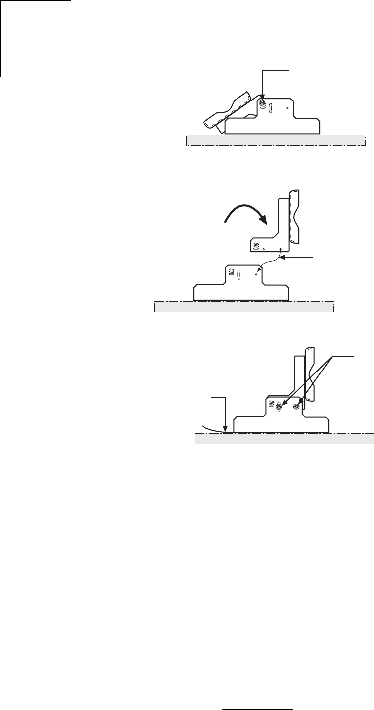
WL266003
Install two bolts
from square hole side,
on each side
2 flat washers
2 lock washes
2 nuts
4)
Remove cardboard strips
5)
Rotate bracket
to vertical
2)
Align square hole
with round hole
3)
Remove 2 bolts
(keep all parts)
1)
Figure 4.5 - 24” Flat Panel Quick Align Mount
41
Wavenet Link AX Installation and Operations Manual
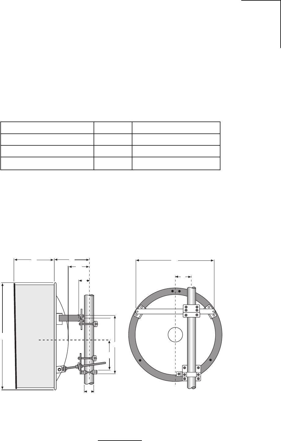
Figure 4.6- 24” Diameter Antenna
WL202027
JH
B
A
P
K
G
Q
D
C
elytSdnaretemaiDannetnA)iBd(niaG)seerged(htdiwmaeBBd3
cilobarap"21
cilobarap"421.821.6
*cilobarap"842.031.3
.tnailpmocCCFtoneradna,ylnoASUehtedistuoesuroferasannetnahsid"84ehT*
200482LW
Table 4.3 - Approximation Table of Parabolic Antennas
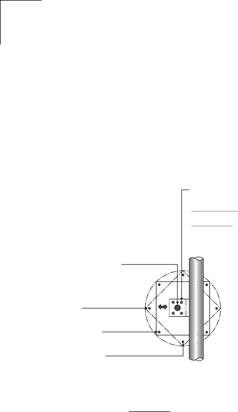
4.2.2 Parabolic Type Antennas, 12”, 24” and 48”
Site Planning
1. For antenna mounting and planning dimensions, see Figure 4.6 and Table 4.4.
2. The antenna is normally assembled with an elevation adjustment range of +50 degrees to
-5 degrees. By inverting the mount, it can be assembled with a +5 degree to -50 degree
range. In either configuration, the antenna centerline can be offset right or left, relative to
the vertical mast pipe (See Figure 4.6) by inverting the Horizontal Tube Assembly.
Table 3.3 reflects the different parabolic antenna dimensions.

42
Wavenet Link AX Installation and Operations Manual
Table 4.4 - 24” Diameter Antenna Dimensions
noisnemiDnoitpircseDannetnA)m6.0(.tf2
AhtgneLtnuoM)mm075("4.22
BtnioPtoviP)mm501("2.4
CtesffOeniLretneC)mm521("0.5
DturtStnuoMlatnoziroHA/N
EturtStnuoMlacitreV.tP.tvP)mm571("8.8
FturtSediSdexiFlatnoziroHA/N
GenilretneCannetnA)mm543("6.31
HhtgneLrotcelfeR)mm513("3.21
JhtgneLduorhStrohS)mm023("5.21
htgneLduorhSgnoL)mm583("1.51
KretemaiDannetnA)mm016("0.42
L)dradnatS(htgneLemodaR)mm043("4.31
NhtpeDturtStnuoMA/N
PxetreVrotcelfeR)mm091("6.7
Q
retemaiDtsaM)mm511-06("5.4"4.2
egnaRelbatsujdAhtumizA °5±
segnaRtnemtsujdAnoitavelE °5-/°05+
820202LW
43
Wavenet Link AX Installation and Operations Manual
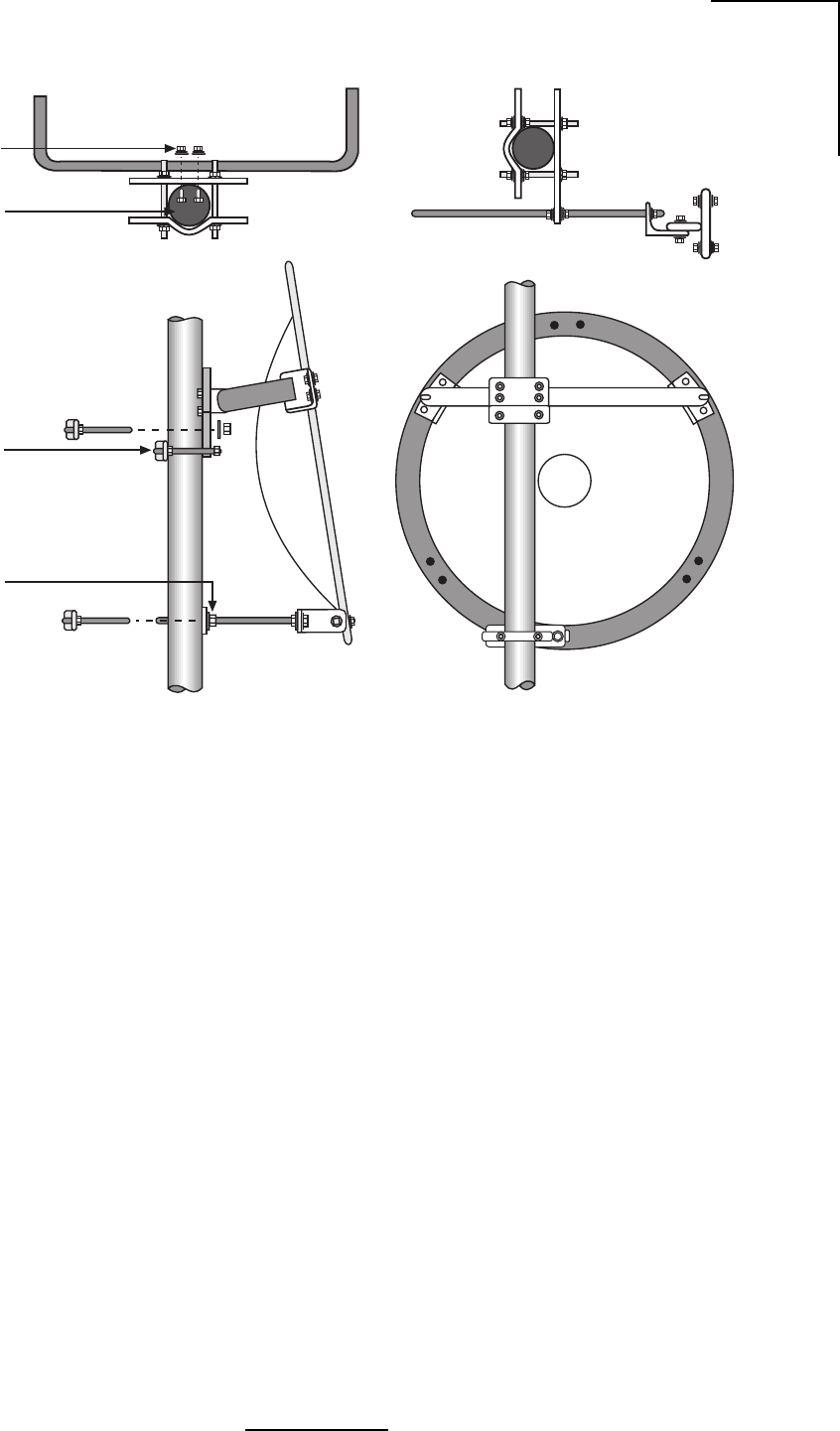
Figure 4.7 - Mount Configuration
WL202029
and Nut (4)
3/8” (10mm)
Round Head
Screw Lockwasher
ø 2.4”- 4.5”
(60-115mm)
Shear Stop
Collar
Elevation
Plate
Unpacking and Preparation
1. Carefully unpack the reflector, mount, shroud (if any), radome (if any) and feed from the
crate. For correct antenna performance, handle all components with care. Set aside the
packaged feed and any shroud or radome. See Figures 4.8 through 4.11.
Caution: The reflector spinning has been formed to a very close-tolerance parabolic shape.
Careful handling and assembly is required to avoid denting or deforming the reflector,
which would degrade the antenna's performance.
2. Inspect for any damaged parts. See Tables 4.5a-4.5d for an inventory of the parts and
hardware shipped with the antenna.
Shroud Attachment
Attach the shroud assembly that is provided with high-performance antennas to the reflector.
The installation procedure is covered by another instruction sheet supplied with the shroud.
Note: Some models have the shroud factory installed.

44
Wavenet Link AX Installation and Operations Manual
Table 4.5a - Contents List, Mount Assembly
rebmuNtraPnoitpircseDytQ
105-57652ylbmessAepiPlaitnaziroH 1
505-52752ylbmessAgnipmalCtsaM 1
2-61322vlaGdoRdedaerhT2
5-52542"1flaHpmalCtsaM1
1210GWFvlaGrehsaW2
1210GUNvlaGrehsaW6
905-52732vlaGrehsaWtilpS4
905-52732yssAgnipmalCtsaM 1
2-61322vlaGdoRdedaerhT2
8-52542flaHpmalCtsaM1
0210GWFvlaGrehsaW2
0210GUNtuNxeH6
0900GWSvlaGrehsaWtilpS4
405-72752yssApotSraehS 1
3-5832doRdedaerhT2
2-52542trohS-flaHpmalCZA2
0310XUNtuNxeH6
0900GWSvlaGrehsaWtilpS4
305-03752yssAdoRnoitavelE 1
6-11632doRnoitavelE1
105-24832yssAtkrBdoRnoitavelE1
1-66652elgnAtroppuSnoitavelE1
0800GOBvlaGtloBxeH1
0210GWFvlaGrehsaW1
0410GWFvlaGrehsaW1
0210GUNvlaGtuNxeH1
5910XUNSStuNxeH4
0900GWSvlaGrehsaWtilpS1
0010GWSvlaGrehsaWtilpS1
430202LW

45
Wavenet Link AX Installation and Operations Manual
Table 4.5b - Contents List, Mount Assembly
rebmuNtraPnoitpircseD.ytQ
105-33752 tiKerawdraHtnuoM1
45-94701.vlaGtloB-U2
2-16532recapS2
5000MDAebuT.zo1ezieS-itnA1
1290XOBtloBxeH6
0210GWFrehsaW4
05000XWFrehsaW21
0210GUN.vlaGtuNxeH4
0600XUN.vlaGtuNxeH6
0900GNPtunlaP4
0500XWS.vlaGrehsaWtilpS6
1-09562 etalPnoitavelE1
1-19562 etalPhtumizA1
6811XOB wercSDHDNR4
0310XUN tuNxeH4
0800XWS rehsaWtilpS4
232-II snoitcurtsnInoitallatsnI1
530202LW
Table 4.5d - Contents List, Reflector Assembly
Table 4.5c - Contents List, Feed Assembly
rebmuNtraPnoitpircseD.ytQkcehC
3-23832A2-nepO'2ES.yssA.lfeR1
030202LW
rebmuNtraPnoitpircseD.ytQ
1-63752pmalCgnitnuoMdeeF4
305-61762058.5-052.5A/SdeeF1
0715TDA071SSD'04x8//7x61/3lytuBkcarTRR1
0500XWF560.x437.0W"4/1rehsaW4
122-IIsnoitcurtsnInoitallatsnI1
0600XUNtuNxeH4
0500XWSrehsaWtilpS4
130202LW
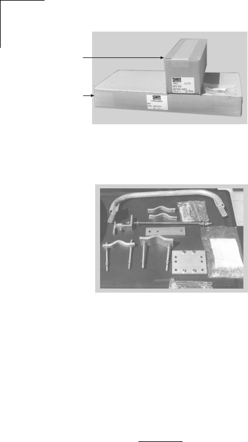
46
Wavenet Link AX Installation and Operations Manual
Figure 4.8 - Mounting Hardware Packed
Figure 4.9 - Mounting Hardware Unpacked
WL202032
Feed Horn
Assembly
Mounting
Hardware
WL202033
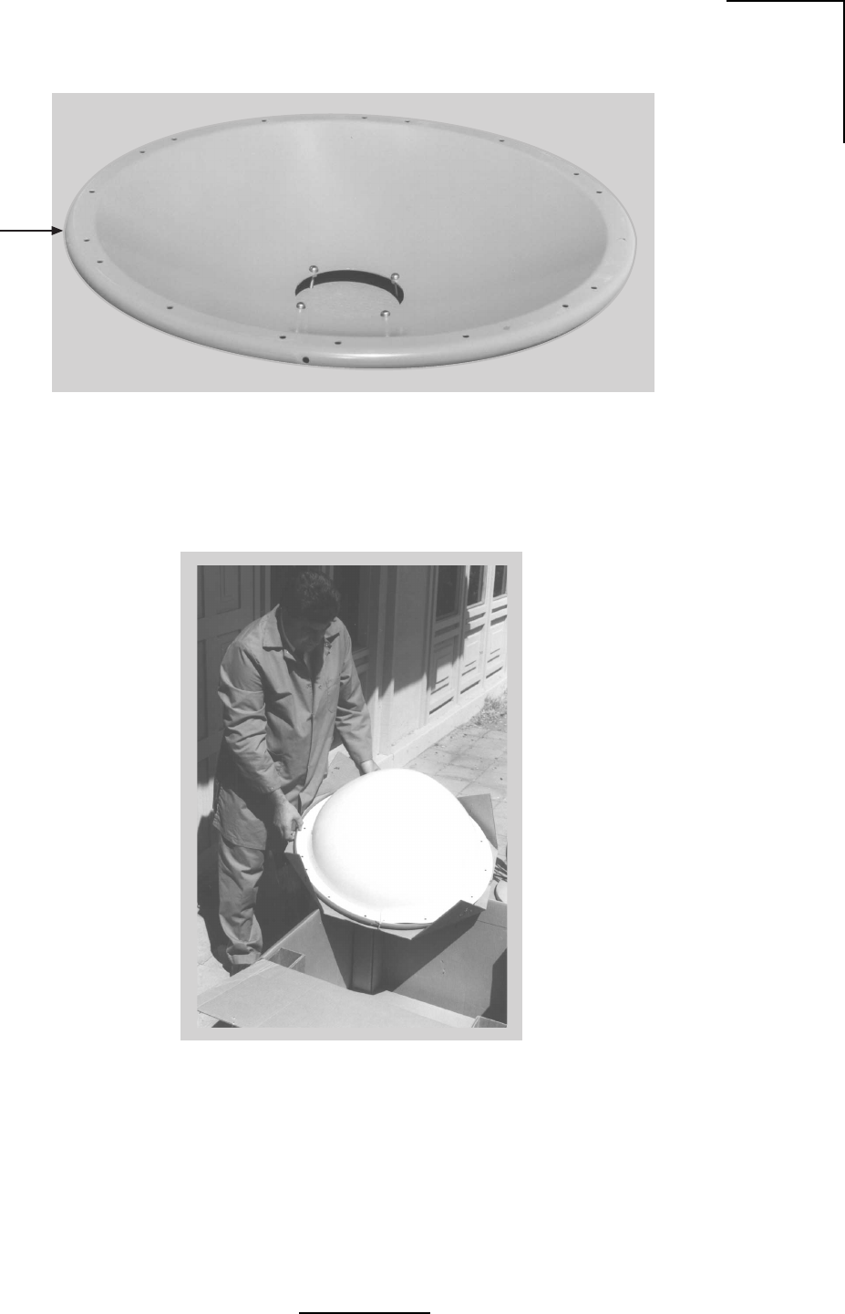
47
Wavenet Link AX Installation and Operations Manual
Figure 4.10 - Parabolic Reflector
Figure 4.11 - Unpacking the Radome
WL202036
Parabolic
Reflector
WL202037
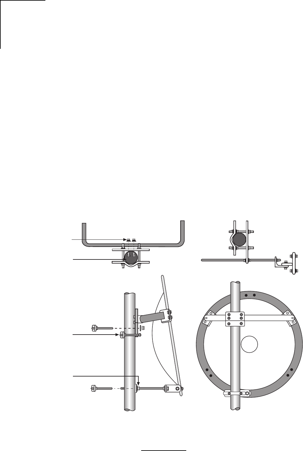
48
Wavenet Link AX Installation and Operations Manual
Figure 4.12 - Antenna Mount Assembly
Mount Assembly and Attachment
1. The reflector should be placed face down, either on the shroud or blocked up on packing
lumber. Locate the Top and Bottom markings stenciled onto the back of the reflector.
2. Loosely attach Top Support Angles to the Horizontal Tube Assembly as shown in Figure
4.12 and 4.13.
3. For desired mount configuration (refer to Figure 4.7), attach the Vertical Tube Assembly
to the Horizontal Tube Assembly as shown in Figure 4.12 and 4.13.
4. Verify proper assembly of the elevation rod hardware as shown in Figure 4.14. Remove
outer hardware and insert rod through elevation plate.
Important: For elevation angles grater than ±20°, Beveled Washers, shown in Figure 4.14,
must be used. However, beveled washers may be used for elevation angles greater than
±10°.
5. Carefully place mount assembly onto antenna backring, taking care not to damage the
reflector. Loosely fasten the Top Support Angles and the Elevation Support Angle to the
antenna backring using 1/2” hardware as shown in Figure 4.12.
6. Verify alignment of the Vertical Assembly with the vertical axis of the reflector and secure
the Top Support Angles and the Elevation Support Angle to the ring.
WL202038
and Nut (4)
3/8” (10mm)
Round Head
Screw Lockwasher
ø 2.4”- 4.5”
(60-115mm)
Shear Stop
Collar
Elevation
Plate
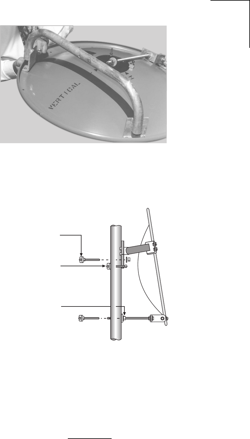
49
Wavenet Link AX Installation and Operations Manual
Figure 4.14 - Elevation Rod Assembly
Figure 4.13 - Antenna Mount Assembly
WL202039
WL202040
Secure Antenna to Mast
Pipe using large and
small Mast Clamps
Attach Shear Stop
Collar on Mast Pipe so
that it will be Under
Azimuth Plate
Position Elevation Plate
on the Mast so elevation
screw is horizontal when
Antenna is aligned
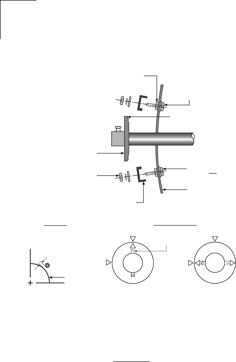
50
Wavenet Link AX Installation and Operations Manual
Feed Installation
Following the instructions provided with the feed assembly, install the feed in the reflector. Refer
to Figures 4.15 through 4.20.
Figure 4.15 - Feed Horn Installation
WL283001
1/4-20 RND. HD.
Screw w/ Split
Lockwasher on
front of Reflector
1/4-20 Hex Nut
tighten securely
See View A-A
Below
Insert feed from rear
orient in desired
polarization Assemble
hardware as
shown in four
locations
Graphite Grease
(packed w/
Antenna Mount)
1/4-20 Hex Nut,
Lockwasher,
Flat Washer
Feed Support Clamp
Reflector
To avoid distorting
reflector do not
overtighten clamps
Caution:
Feed Polarization
Horizontal
H
V
H
Vertical
V
Optional Port
location
View A-A
Reflector
center hole
Align face of nuts
w/ edge of hole
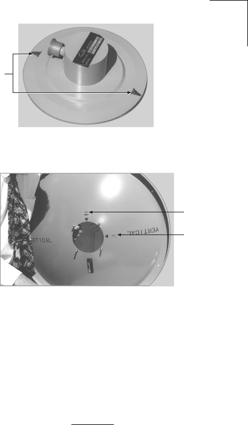
51
Wavenet Link AX Installation and Operations Manual
Figure 4.16 - Feed Horn Polarization Markings
Figure 4.17 - Parabola Rear View Showing Polarization Reference Markers
WL202042
Feed Horn
Polarization
Markings
WL202043
Horizontal
Polarization
Marking
Vertical
Polarization
Marking
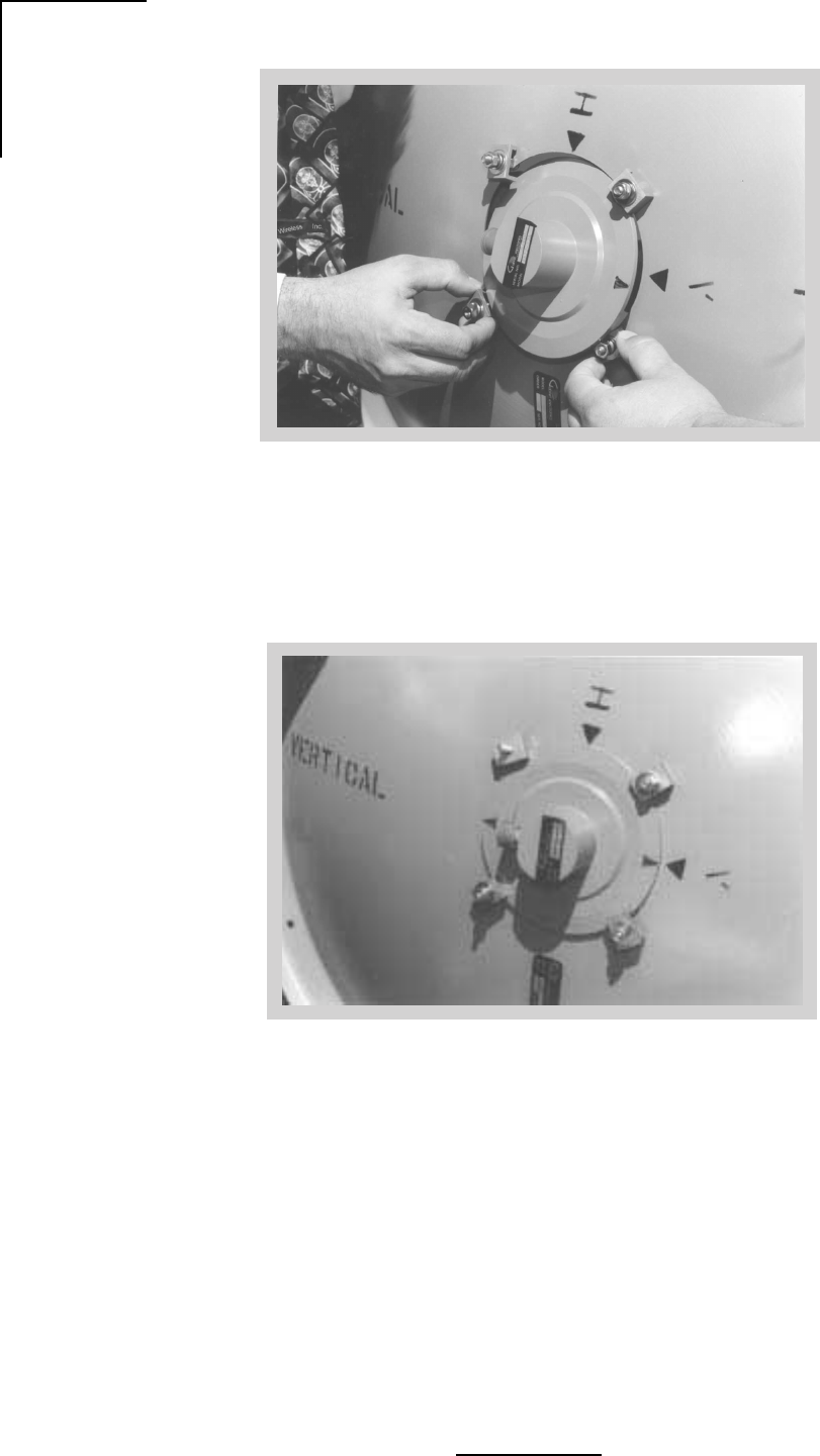
52
Wavenet Link AX Installation and Operations Manual
Figure 4.18 - Feed Horn Installation
Figure 4.19 - Feed Horn Installation for Vertical Polarized Operation
WL202045
WL202044
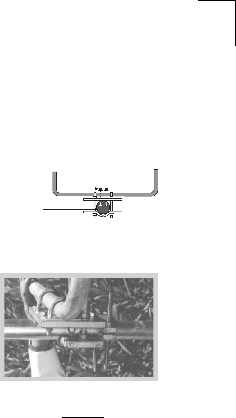
53
Wavenet Link AX Installation and Operations Manual
Figure 4.21 - Azimuth Adjustment Clamp Assembly
Radome Installation
Molded Radomes (normally optional on standard antennas) should be installed following the
instructions provided.
Azimuth Adjustment Clamp/Shear Stop Installation
1. Verify proper assembly of the azimuth clamp/shear stop clamp as shown in Figure 4.20 and
4.21. Securely attach the shear stop clamp to the mast pipe as shown, orienting it as nearly
as possible to the antenna boresight direction, and square to the mast axis. Note that the
shear stop clamp used on the two foot antennas also provides the azimuth adjustment.
2. Refer to Figure 4.6 for the position of the antenna centerline relative to the shear stop
clamp. The clamp must be mounted to provide support during installation and azimuth
adjustment.
Figure 4.20 - Azimuth Clamp/Shear Stop Assembly
3/8” (10mm)
Round Head
Screw Lockwasher
and Nut (4)
ø 2.4” - 4.5”
(60-115mm)
WL202046
WL202047
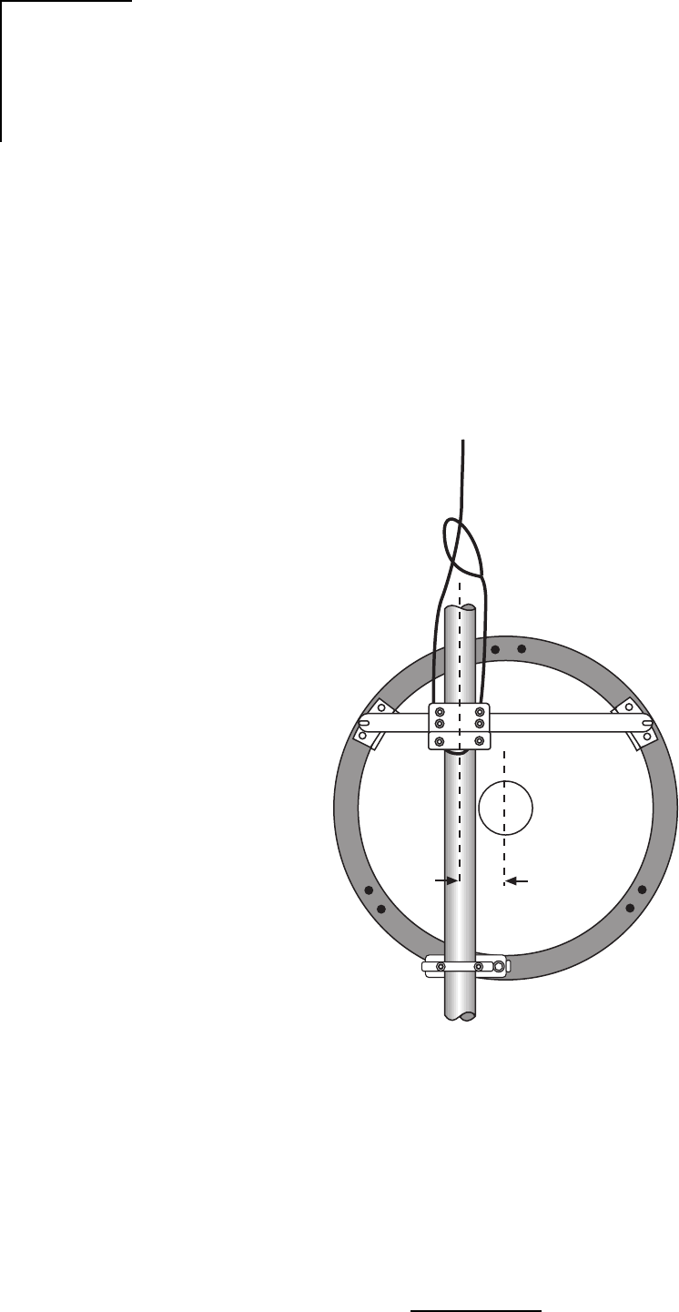
54
Wavenet Link AX Installation and Operations Manual
Antenna Hoisting and Installation
1. Attach a hoist strap around the vertical assembly or the horizontal assembly as shown in
Figure 4.22. Do not hoist by the elevation rod. Make sure that the vertical assembly is
unobstructed where it will mount against the mast pipe.
2. Attach tag lines and carefully lift the antenna into position, resting the vertical assembly on
the shear stop clamp.
3. Fasten the mount to the mast pipe with 1/2” U-bolts. The antenna must be free to rotate
during azimuth adjustment, so tighten only enough to close the gap between the mast and
vertical channel. Do not leave the antenna loose for any extended period of time, i.e.
overnight.
Figure 4.22 - Hoisting the Antenna
WL202048
5”
(127mm)

55
Wavenet Link AX Installation and Operations Manual
General Antenna Alignment Procedures
Normally the antenna is aligned by performing azimuth and elevation adjustments and
elevation adjustments as necessary until the peak signal is obtained. It may be helpful to re-
peak one adjustment before finalizing or locking down the other.
Warning: Damage to the antenna can occur if azimuth or elevation adjustments are
attempted without loosening the proper connections as described in the following steps.
Azimuth Adjustment
1. Be sure the mast pipe U-bolts are just loose enough to allow mount rotation while
maintaining complete contact between the mount and the mast pipe.
2. Turn the long stainless steel azimuth screws against the mounting channel. By alternately
turning one azimuth adjustment screw out and the other in, the antenna can be rotated to
the desired azimuth angle. Approximately 1 turn changes the azimuth direction by 1°. Avoid
adjusting the antenna beyond the ±5° provided by the azimuth clamp as this can damage
the adjusting hardware. Fasten the antenna to the mast pipe and reposition the clamp if
needed.
Note: By securing the mount to the mast pipe and realigning the azimuth clamp with the
antenna boresight, more reliable and precise azimuth adjustments can be achieved.
After all adjustments are made, tighten both of the azimuth screws against the channel and
secure with the lock nuts provided.
3. Tighten the mast pipe U-bolts while maintaining the peak signal by alternating from left to
right in 1/4 turn intervals.
Elevation Adjustment
1. Insure that both of the bolts connecting the mount to the Top Support Angles and the
pivoting Elevation Angle (refer to Figures 4.12 and 4.14) are just loose enough to allow
resisted rotation.
2. Back the outer nuts on the elevation rod away from the bottom mount plate to allow some
fine adjustment range.
3. Turn the inside nut (with flat washer) on the elevation rod to adjust the elevation angle.
Approximately 5 turns changes the elevation by 1°. Remember, for elevation greater than
20°, install the two beveled washers as shown in Figure 4.14.
4. After all adjustments are made, lock the nut against the bottom mount plate. Tighten the
angle pivot bolt and support bracket bolts.
Important: Be sure to tighten all hardware after final adjustments and insure that split
lockwashers, palnuts, or jam nuts are used where provided.

56
Wavenet Link AX Installation and Operations Manual
Table 4.6 - Nut Tightening Procedures
Inspection and Maintenance
1. Before leaving the installation, check that all hardware on the mount, shroud, radome, and
feed is tight and that nuts are locked in place.
2. Inspection of the antenna should be performed at lease once a year to check its condition
and to insure safe operation and maintenance. Qualified personnel, knowledgeable and
experienced in antenna installations, are required for this inspection.
Supplemental Information
Table 4.6 is provided for installers unfamiliar with adequate nut tightening procedures for use
on stainless steel bolts, U-bolts, galvanized bolts or any bolts without the ASTM-”A325” marking
on the head. Disregard these recommendations when specific tightening requirements are
given.
Note: It is not recommended to reuse a palnut that has already been fully tightened or
deformed in any way. It should be replaced by a new palnut.
Weather Proofing the Type N Female Connector on Feeds
Remove the protective cover from the end of the feed and mate the connectors, screwing the
male connector firmly onto the feed.
Important: After connecting the coaxial cable, wrap the Type N connector with the gray butyl
rubber, squeezing it firmly around all joints to make a continuous seal. Finish the
weatherproofing by wrapping the butyl rubber with several layers of black PVC tape (not
supplied).
eziStloBlanimoNeuqroTtuNeuqroTtunkcoLtunlaP
"4/1.bl/.ni05.bl/.ni04
"61/5.bl/.ni201.bl/.ni06
"8/3.bl/.tf51.bl/.ni58
"61/7.bl/.tf42.bl/.tf51
"2/1.bl/.tf73.bl/.tf61
"8/5.bl/.tf47.bl/.tf82
"4/3.bl/.tf571.bl/.tf44
"8/7.bl/.tf212.bl/.tf15
"1.bl/.tf813.bl/.tf95
940202LW
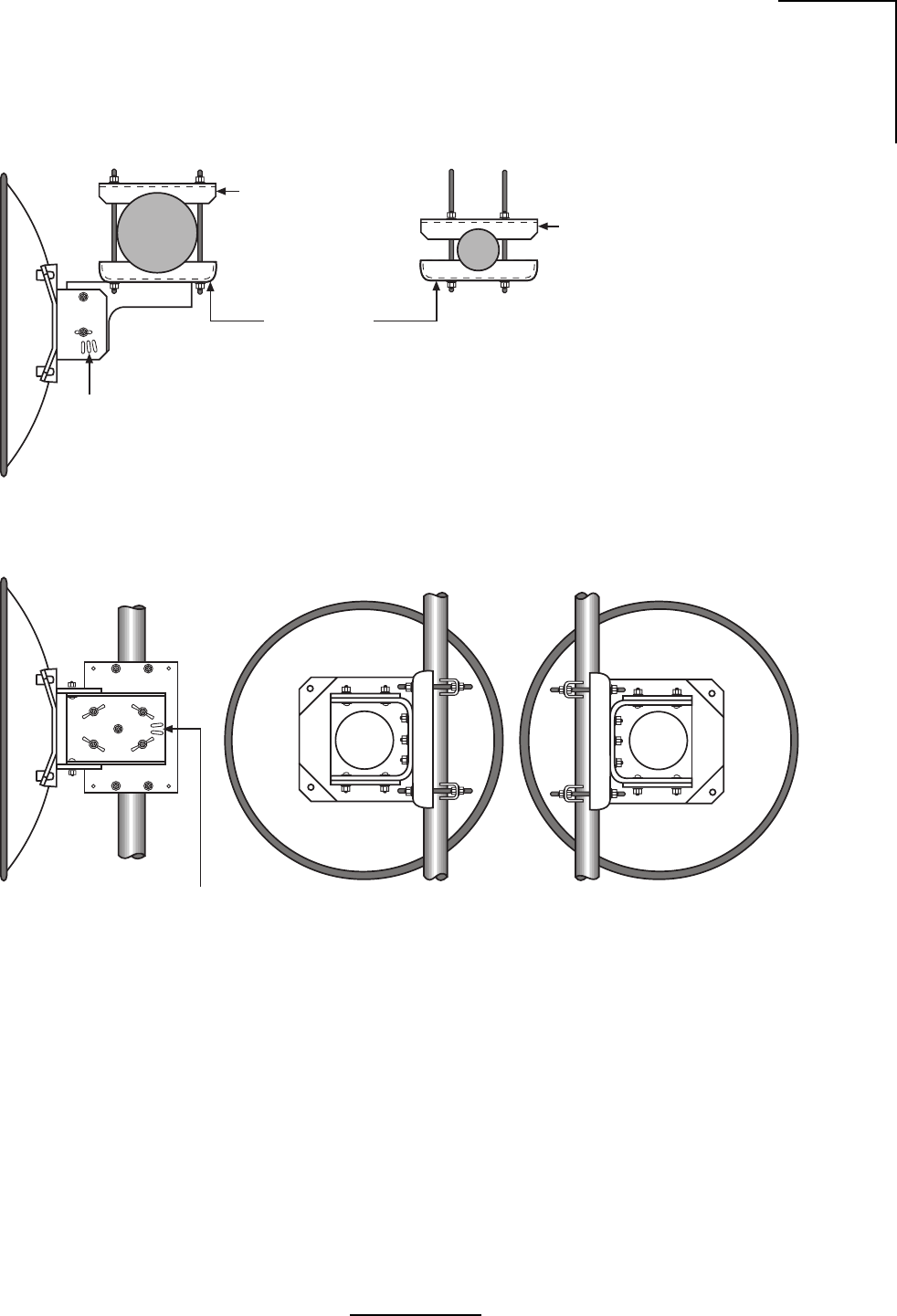
57
Wavenet Link AX Installation and Operations Manual
Top View
Side View Rear View (Left Offset)* Rear View (Right Offset)*
* To change offset, invert Antenna.
WL264001
Elevation
Adjustment
Slots
Saddle Bracket
Mast Clamp Kit for
1.9 (48mm) thru
4.5 (114mm) dia. Masts Re-Assemble Mast Clamp Kit
as shown for 1.9 (48mm) dia. Masts
Azimuth
Adjustment
Slots
Figure 4.23 - Adjustable Parabolic Antenna Mount
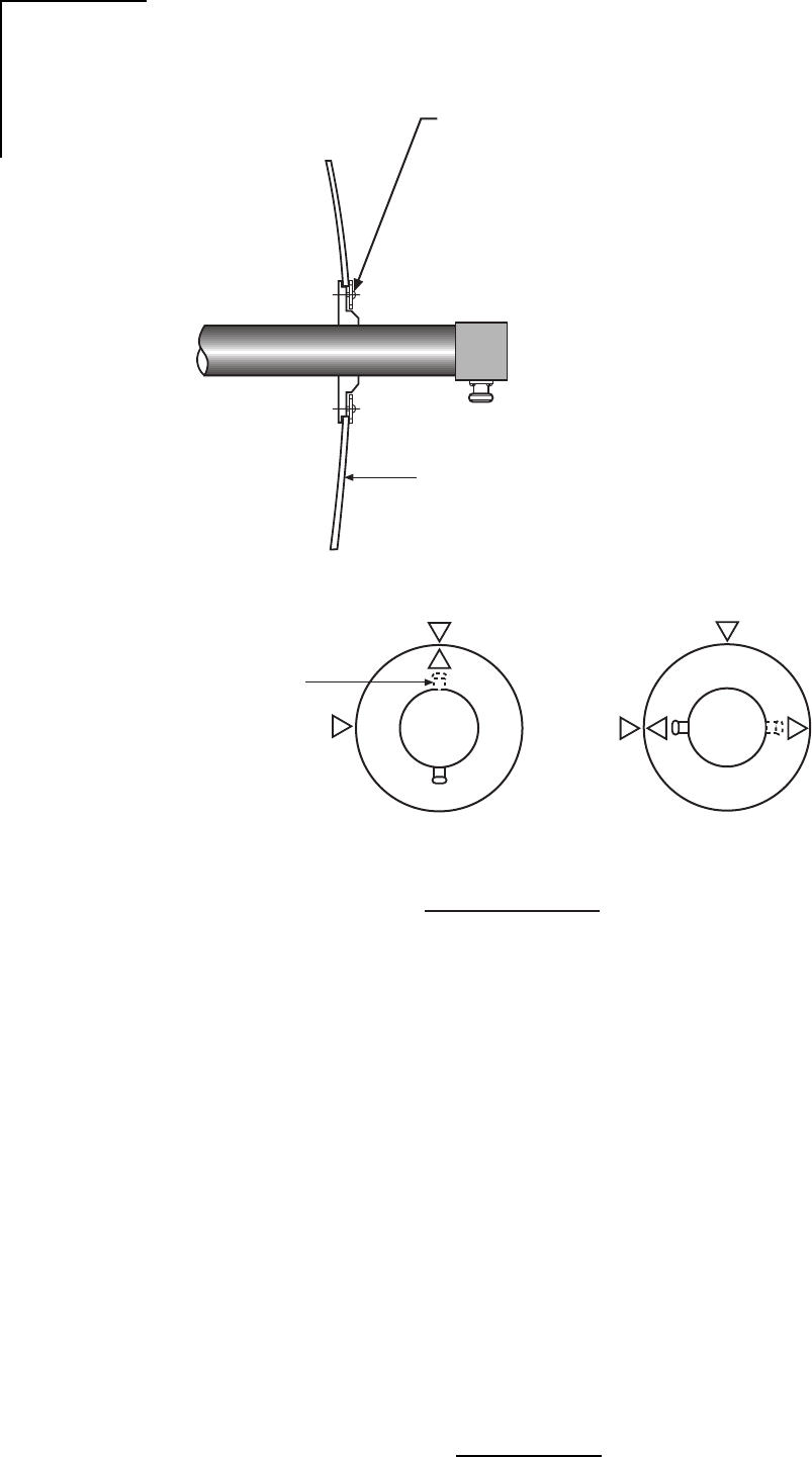
58
Wavenet Link AX Installation and Operations Manual
Reflector
WL265001
Horizontal
H
V
H
Vertical
V
Optional Port
location
Assemble 6-32 screws and clamps to feed
(4) places.
1)
Orient clamps to retracted position.
2)
Insert feed through front of reflector.
3)
Orient clamps to extended position, rotate
feed for proper polarization and tighten
clamp screws.
4)
Feed Polarization
Rear View of Feed
Figure 4.24a - Feed Assembly Plane Polarized
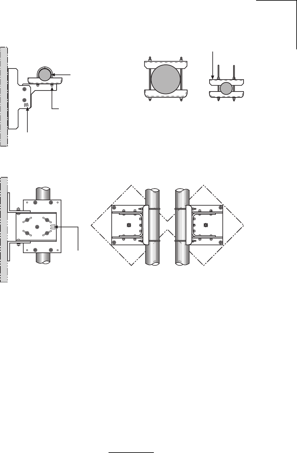
59
Wavenet Link AX Installation and Operations Manual
2 3/8” (60mm)
dia Mast
(2) 1/4” U-Bolt w/
Washer, Lockwashers
and Nuts
Azimuth
Adjustment
Slots
Top View
WL265002
Re-Assemble Mast
Clamp Kit as shown for
1.9 (48mm) dia. Masts
Elevation
adjustment
slots
Side View Rear View
Left Offset Rear View
Right Offset
Optional Mast Clamp Kit
for 1.9 (48mm) dia. thru
4.5 (114mm) dia. Masts
Figure 4.24b- Feed Assembly Plane Polarized

60
Wavenet Link AX Installation and Operations Manual
4.2.2 Wall Mount
Figure 4.25 - Ground Connection
TBA
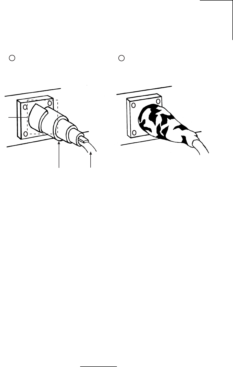
61
Wavenet Link AX Installation and Operations Manual
4.3 RF Cable Install and Seal
WI291001
Wrap material around the
connector and onto the
Coax as shown
The Sealing Material
will bond to the
connector and Coax
Cable providing a
moisture barrier
Connector
Seal Material Coax
12
Figure 4.26 - RF Cable Install and Seal

62
Wavenet Link AX Installation and Operations Manual

63
WaveNet Link AX Installation and Operations Manual
5.0 Maintenance and Troubleshooting
The Link AX contains static sensitive components, and has no user-serviceable parts.
5.1 Link AX Maintenance
The Link AX is designed to operate with no scheduled maintenance activities. Wireless Inc.
recommends a bi-annual inspection of the following to ensure peak operating performance:
a) Verification of RSSI voltage
b) Examination of the antenna mount and ensure mounting hardware is secure
c) Examination of “siamesed” cable for signs of unusual wear or tear
d) Check all connections and verify all are secure
e) Verify power supply voltages are within tolerance
5.1.1 RSSI Voltage
The Wireless Customer Service department recommends a quarterly check of the Link AX’s
RSSI voltage. Variations in the RSSI voltage could be an indicator of antenna or antenna feed
movement, loose or improper RF cabling or connectorization, path obstructions or reflections,
etc.

64
WaveNet Link AX Installation and Operations Manual
5.2 Where To Get Further Assistance
Your primary source of assistance is the support staff of the organization from which you
purchased this product. The Wireless, Inc. support staff should only be contacted directly if you
purchased this product directly from Wireless, Inc., or if you are unable to obtain sufficient
assistance from your primary support contact.
General Product and Company Information
Wireless, Inc.
5452 Betsy Ross Drive
Santa Clara, CA 95454-1101
USA
Tel.: +408 727 8383
Fax: +408 727 1259
E-mail: info@wire-less-inc.com
Website: www.wire-less-inc.com
Detailed Product Information, Sales/Pricing Information and Pre-Sales Technical
Support
Wireless, Inc.
Sales Department
5452 Betsy Ross Drive
Santa Clara, CA 95054-1101
USA
Tel: +408 727 8383
Fax: +408 727 0990
E-mail: sales@wire-less-inc.com
Website: www.wire-less-inc.com
Post-Sales Technical Support (Customer Service)
To assist you with field issues and, if necessary, to arrange for repair services, Wireless, Inc.'s
Customer Service department can be reached via telephone, facsimile, e-mail, mail, or through
our Website.

65
WaveNet Link AX Installation and Operations Manual
5.3 Return Procedure
All material returned to Wireless, Inc. must be accompanied by a Return Material Authorization
(RMA) number from Wireless, Inc.'s Customer Service department. If you purchased your
Wireless, Inc. product through a distributor, the Wireless RMA number should be obtained
through the distributor. An RMA number is necessary to assure proper tracking and handling
of returned material at the factory. Wireless, Inc. reserves the right to refuse shipments not
accompanied by an RMA number. Refused shipments will be returned to the shipper via collect
freight.
To obtain an RMA number, contact Wireless, Inc. as follows:
Telephone: +408 727 8383
Fax: +408 727 1259
E-mail: customerservice@wire-less-inc.com
The following information will be required to issue an RMA number:
•Part Number
•Serial Number
•Failure Description
•Contact person, telephone, and fax numbers
•Ship-to address
•Bill-to address*
•Customer purchase order* (P.O.) or reference number
* Required for non-warranty repair services. For non-warranty repair services, an RMA
number will be issued when Wireless, Inc. acknowledges the purchase order.
Important - All non-U.S. returns must include 5 copies of proforma/customs invoice for each
shipment which lists:
•RMA number
•Value of items
•Description of items (including the Wireless model or part number)
Please send all returns to:
Wireless, Inc.
Attn: RMA Department
5452 Betsy Ross Drive
Santa Clara, CA 95054-1101
USA
RMA No. __________
The customer is responsible to properly label and package repairs and prepay shipping to
Wireless, Inc. If possible, the original packaging material should be used to return electronic
parts. The RMA number must be visible on the outside of all packages returned. Unless other
arrangements have been made, all repairs are shipped back to the customer prepaid via ground
carrier.

66
WaveNet Link AX Installation and Operations Manual

A-1
WaveNet Link AX Installation and Operations Manual
Appendix A Grounding Practices and Lightning
Protection Information
General
Good grounding (“earthing”) practices, when used in telecommunications, have some direct
benefits which can help you maximize the up time of your system as well as ensure the safety
of those people working on the system. Among these benefits are:
1. Protection of personnel from electric shock and fire hazards.
2. Reduction of radiated and conducted electromagnetic susceptibility.
3. Improved system tolerance to discharge of electrostatic energy and lightning interference.
4. Minimized service interruptions and service damage.
There is no practice or formula which can completely eliminate the above risks, but we at
Wireless, Inc. believe that good grounding and bonding practices can significantly reduce the
risk of many of these hazards. We have included a bibliography at the end of this appendix which
contains several publications that are readily available and contain detailed information on
many aspects of grounding systems and their design, implementation, measurement, and
maintenance.
Please note that every telecommunication site is unique, and must be evaluated accordingly.
The following information is provided for generic reference and educational purposes only. The
grounding plans and practices for a given site should only be established and accomplished by
trained professionals, working in accordance with local practices and regulations.
Ground Connections
There should be a grounding plan designed at the outset of site design in order to provide the
best grounding procedures and to minimize ground loop currents. This should be achieved by
connecting the outer conductors of the cables through a large section copper strap to a central
grounding point and the size of the conductor should be increased as each branch path is
added. The final conductor should be connected directly to the grounding system. For a radio
site a single copper grounding rod is insufficient because its impedance is likely to be too high.
Lightning Protection
Radio sites can be particularly prone to lightning strikes by virtue of their normally exposed
locations and the presence of relatively tall antenna support structures.
It is not possible to provide and guarantee complete protection from the effects of lightning;
however, they can be significantly reduced by careful attention to grounding, protection
devices, and the layout of the site itself.
Reference should also be made to various publications, some of which are listed in the
Bibliography. Where any site owner or user is in doubt about the protection requirements for any
particular location, the appropriate authority should be consulted.

A-2
WaveNet Link AX Installation and Operations Manual
Protection Arrangements
The purpose of any protection arrangement should be to provide a suitable path to ground for
the lightning current, to ensure adequate bonding between structures and all metalwork on the
site and the common grounding system in order to reduce the side flashing, and to attempt to
prevent the entry of flashes or surges into the building.
The resistance to ground should be kept to a minimum and a value of less than 10-ohms is
recommended. The most important feature is that the system should ideally be at equal
potential across the entire site.
Certain authorities and service providers have their own particular practices which have to be
followed where applicable.
Arrangements will vary considerably from very simple sites to complicated sites with multiple
buildings, antenna support structures and associated equipment, and may involve integration
with existing systems. Such systems may require upgrading.
Lightning conductors
Down conductors, bonding interconnections, ground rings and radial tapes should be of
uninsulated 000 AWG copper cable or solid copper tape with a minimum cross section of 25 x
3 mm with all connections protected by non reactive paste.
Protected test points should be included if appropriate, and sacrificial ground lugs should be
clearly marked and easily accessible for periodic inspection.
Grounding of antenna support structures
A structure will generally act as its own lightning conductor and therefore will not require an
additional conductor from the top to the base. A lightning rod may be required to extend the zone
of protection to protect equipment mounted on the top of the structure. The lightning rod should
extend 2.5-meters above the highest equipment.
Ground mounted support structures should be connected at their base to a ground ring via
sacrificial ground lugs. Towers should have a connection from each leg.
A ground ring should consist of copper cable or solid copper tape with ground rods equally
spaced at 2-meter intervals around the base of the structure as close to it as possible, buried
approximately 0.6-meters deep where soil conditions allow. An alternative method using radials
rather than rings is detailed in “The ‘Grounds’ for Lightning and EMP Protection”, second
edition, published by PolyPhaser Corporation.
The ground ring should be connected to the main building ground by the most direct route,
buried as appropriate.
Roof mounted structures should be connected to the main building ground by the most direct
route using sacrificial lugs and copper cable or tape as appropriate. Tower guy wires should be
directly bonded at their lowest point to a suitable ground electrode or connected to the site
ground by the most direct route.

A-3
WaveNet Link AX Installation and Operations Manual
Grounding of feeders
All antenna feeders should be bonded to the tower at the upper and lower ends and grounded
at the point of entry into the building. Weatherproof grounding kits are available from antenna
manufacturers.
Note: Many of the cables used by Wireless, Inc. have braided rather than solid outer
conductors; this type of grounding is not appropriate. In these cases we recommend the
use of Wireless, Inc. approved lightning arrestors. For information on lightning arrestors,
please contact Wireless, Inc.’s Customer Service department.
Grounding of buildings
A ground ring ideally should surround the building and be connected to individual grounds
associated with feeder entry, antenna support structure, building lightning conductor, equip-
ment room, main AC supply and other facilities. Each connection should be made by the most
direct route in order to minimize interaction between the different grounding functions.
The ground ring should consist of copper cable or tape with electrodes 2- meters or greater in
length, buried to a depth of 0.6-meters and at a distance from the building not to exceed 1-meter.
Buildings may require lightning rods where they are not within the zone of another protected
structure.
Bibliography
ITU - T K.40 Protection against LEMP in telecommunications centres
ITU - T K.27 Bonding configurations and earthing inside a telecommuni-
cation building
ITU - T K.35 Bonding configurations and earthing at remote electronic
sites
ITU - T K.39 Risk assessment of damages to telecommunications sites
due to lightning discharges
ITU - T Lightning Handbook The protection of telecommunication lines and equipment
against lightning discharges
IEEE Emerald Book - Powering and Grounding
The “Grounds” for Lightning and EMP Protection, second edition
Published by PolyPhaser Corporation

A-4
WaveNet Link AX Installation and Operations Manual