Wistron NeWeb UWMWBT-CWM01 MOD-SM WNC BLUETOOTH/WLAN CWM-01 User Manual WBT Manual for FCC 20111227
Wistron NeWeb Corporation MOD-SM WNC BLUETOOTH/WLAN CWM-01 WBT Manual for FCC 20111227
UserManual.wiki
>
Wistron NeWeb
>
UWMWBT CWM01 User Manual
User Manual
Navigation menu
Upload a User Manual
Namespaces
Wiki Guide
HTML
PDF
Info
Views
User Manual
Discussion / Help
Navigation
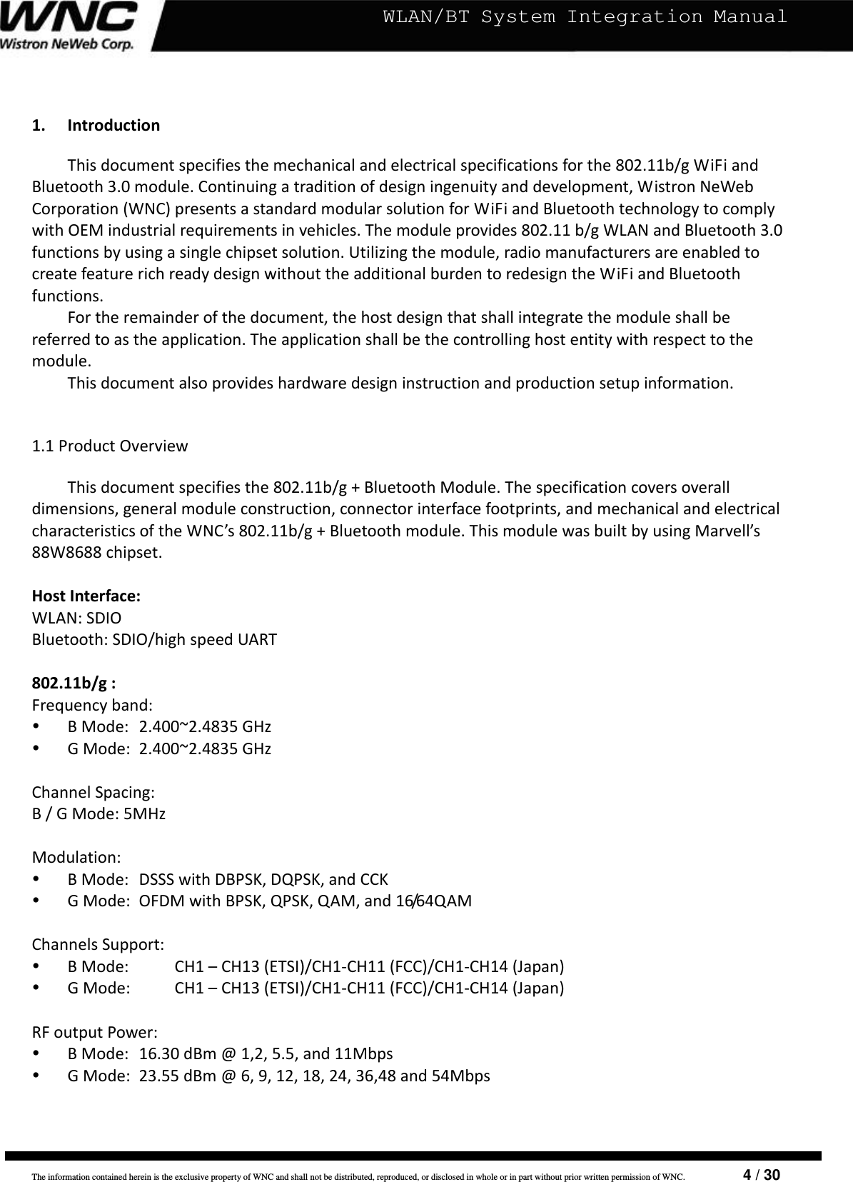
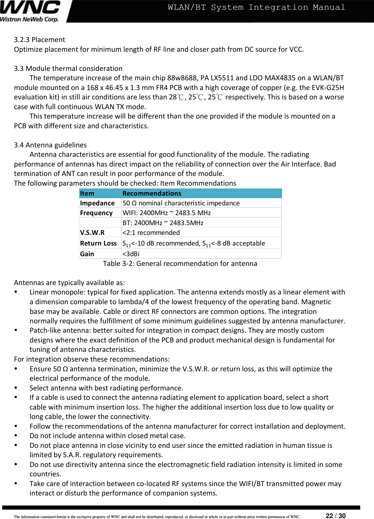
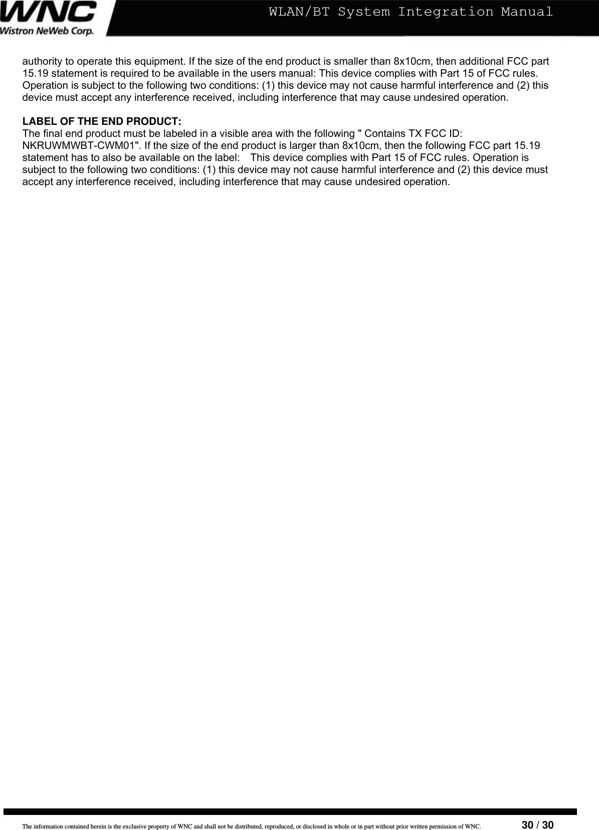
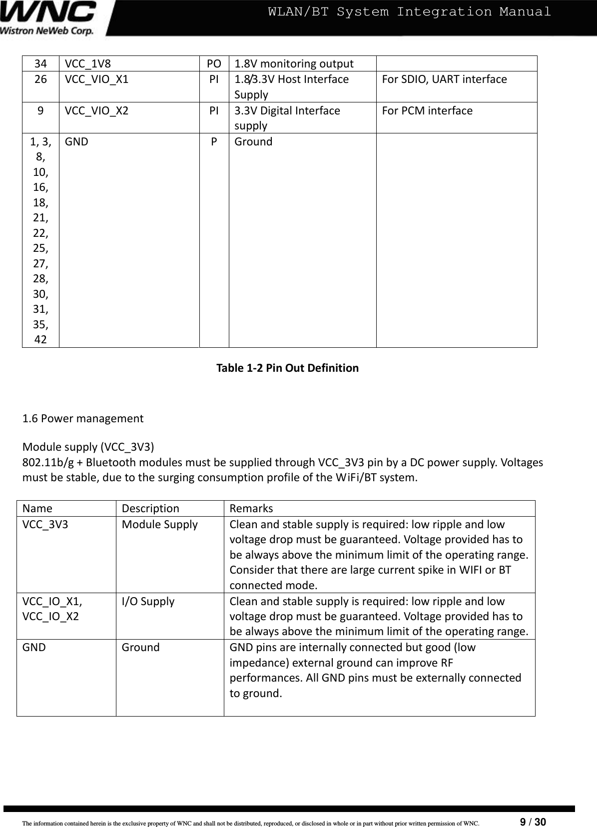
![The information contained herein is the exclusive property of WNC and shall not be distributed, reproduced, or disclosed in whole or in part without prior written permission of WNC. 7 / 30 WLAN/BT System Integration Manual1.5ModulePinOutThemoduleisdesignedas54pinsolderjointmoduleforSMTprocess.Thepin‐outisillustratedinthefigure1‐2.UART_TXGNDGNDGNDUART_RXS D_ DATA[2 ]45GNDGNDVCC_1V828GNDGNDGNDGNDBT_ RFWLAN_RFBT_P CM_DINBT_P CM_ CLKBT_P CM_ DO UTBT_ PCM _SY NC1GNDVCC_VIO_X2GNDJTAG_TCKJTAG_TDIJTAG_TRSTnJTAG_ TMS _S YSJTAG_TDO18S D_ DATA[3 ]40 3035S D_ DATA[0 ]UART_RTSS D_ DATA[1 ]SD_ CMDS D_CLKVCC_3V3VCC_3V3VCC_3V0VCC_VIO_X1GNDGNDGND27VCC_3V3VCC_3V3VCC_WLAN_ ANT_DIAGGNDWLAN_ANT_DIAG25201951015SLEEP _ CLKANT_SEL _PRESETn46VCC_BT _ANT_DIAGUART_CTSBT _AN T_ D IAG5054JTAG_TMS_CPUNCANT_ SEL _NFigure1‐2Pinoutof802.11b/g+BluetoothmoduleThepindefinitionisshowninthefollowingtable1‐2.Pin#SignalNameI/OSignalDescriptionSignalCharacteristicsSDIOInterface36SD_CLKI/OSDIOclock37SD_CMDI/OSDIOcommandline39SD_DAT_0I/OSDIOdatalinebit038SD_DAT_1I/OSDIOdatalinebit141SD_DAT_2I/OSDIOdatalinebit240SD_DAT_3I/OSDIOdatalinebit3UARTInterface45TXDOUARTserialdataoutput44RXDIUARTserialdatainput46CTSIUARTCleartosendsignal43RTSOUARTReadytosendsignal WLANandBluetoothRFInterface](https://usermanual.wiki/Wistron-NeWeb/UWMWBT-CWM01/User-Guide-1610650-Page-7.png)
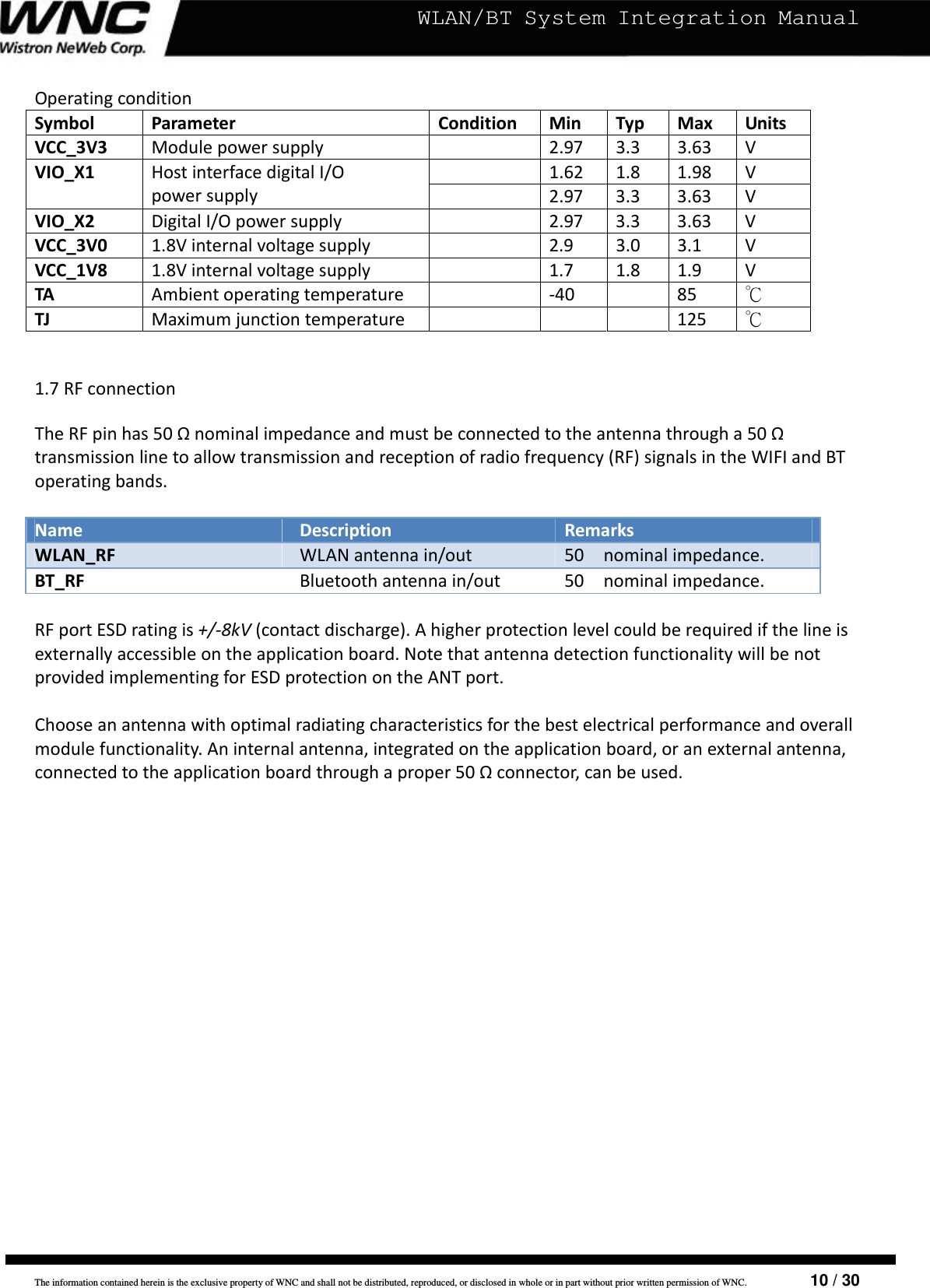
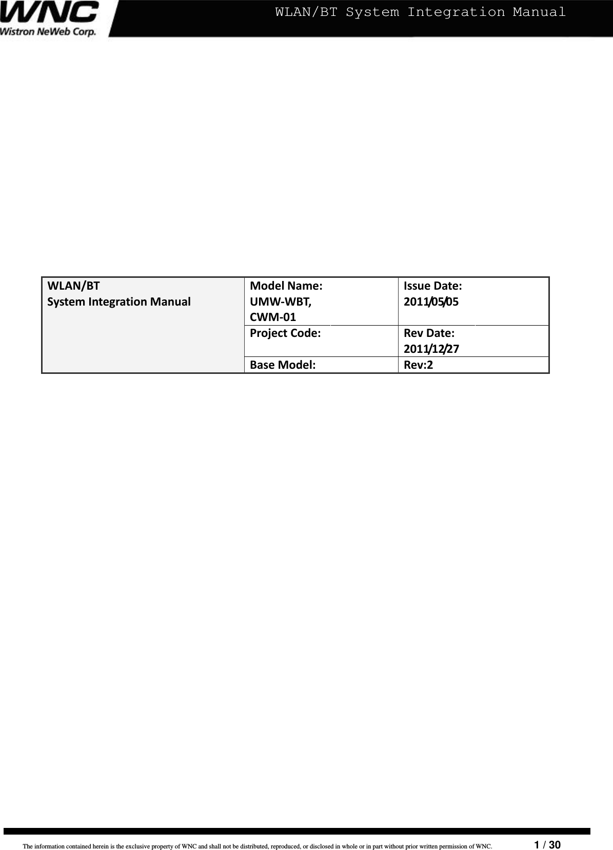
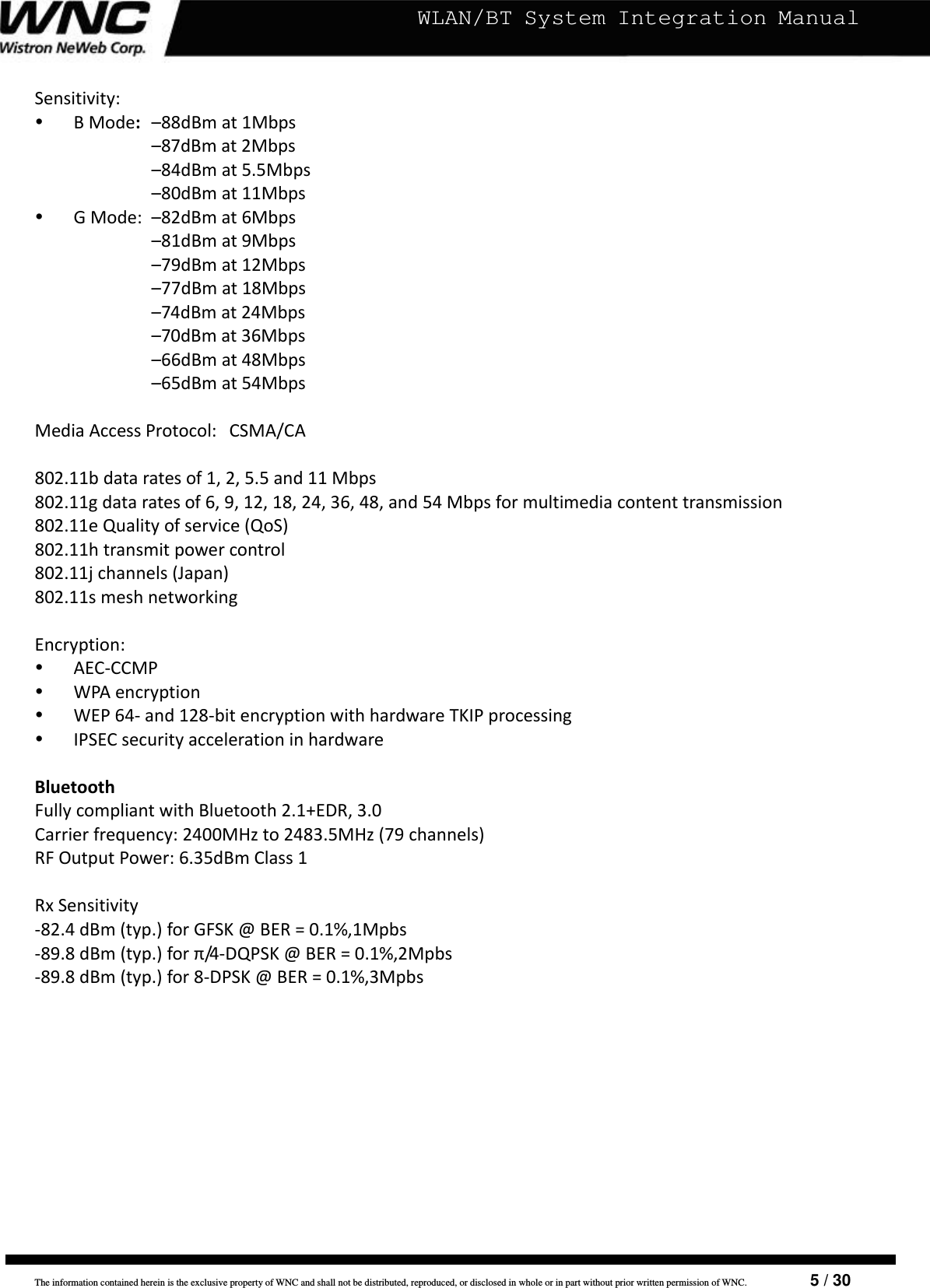
![The information contained herein is the exclusive property of WNC and shall not be distributed, reproduced, or disclosed in whole or in part without prior written permission of WNC. 11 / 30 WLAN/BT System Integration Manual2.InterfacesThischapterdescribestheinterfacesontheWLAN/BTmodules:SDIO,UART,PCM,JTAG,Antennadiagnosis.2.1SDIOInterfaceThemodulesupportsaSDIOdeviceinterfacethatconformstotheindustrystandardSDIOfullspeedcardspecificationandallowsahostcontrollerusingtheSDIObusprotocoltoaccesstheWLANand/orBluetoothdevice.ThisdevicealsosupportshighspeedmodeasdefinedinSDIO1.2specification.TheSDIOinterfacesupportsdualfunctionoperations,forWLANandBluetooth.DualfunctionalityallowstheuseofindependentclientdriversforWALNand/orBluetoothonthehostplatform.Sincethesefunctionssharethesamephysicalinterface,anarbitrationschemeisrequiredintheSDIObusdriveronthehostplatform.TheSDIOinterfacesupportsSPI,1‐bitSDIO,4‐bitSDIOtransfermodesatthefullclockrangeof0to50MHz.2.1.1SDIOInterfaceSignalDescriptionPinNameSignalNameTypeDescriptionSD_CLKCLKI/OSDIO4‐bitmode:ClockSDIO1‐bitmode:ClockSDIOSPImode:ClockSD_CMDCMDI/OSDIO4‐bitmode:Command/ResponseSDIO1‐bitmode:CommandlineSDIOSPImode:DatainSD_DAT_0DAT0I/OSDIO4‐bitmode:Datalinebit[0]SDIO1‐bitmode:DatalineSDIOSPImode:DataoutSD_DAT_1DAT1I/OSDIO4‐bitmode:Datalinebit[1]SDIO1‐bitmode:InterruptSDIOSPImode:InterruptSD_DAT_2DAT2I/OSDIO4‐bitmode:Datalinebit[2]SDIO1‐bitmode:ReadWait(optional)SDIOSPImode:Reserved](https://usermanual.wiki/Wistron-NeWeb/UWMWBT-CWM01/User-Guide-1610650-Page-11.png)
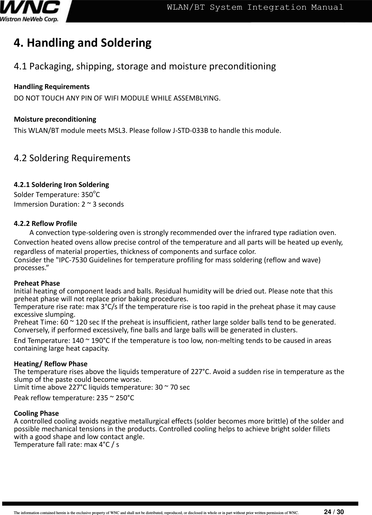
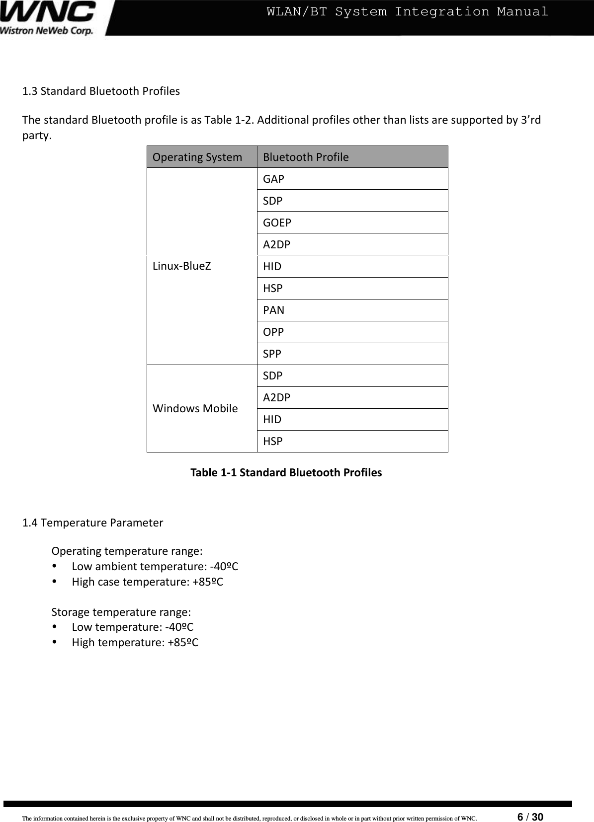
![The information contained herein is the exclusive property of WNC and shall not be distributed, reproduced, or disclosed in whole or in part without prior written permission of WNC. 12 / 30 WLAN/BT System Integration ManualSD_DAT_3DAT3I/OSDIO4‐bitmode:Datalinebit[3]SDIO1‐bitmode:NotusedSDIOSPImode:Chipselect(Negativetrue)2.1.2SDIOConnection/FunctionFigure1.1SDIOPhysicalConnection–4bitmodeNote:In4‐bitSDIOmode,dataistransferredonall4datapins(DAT[3:0]),andtheinterruptpinisnotavailableforexclusiveuseasitisutilizedasadatatransferline.Thus,iftheinterruptfunctionisrequired,aspecialtimingisrequiredtoprovideinterrupts.The4‐bitSDIOmodeprovidesthehighestdatatransferpossible,upto100Mbps.2.2UARTInterfaceThemodulesupportsahighspeedUARTinterface,complianttotheindustrystandard16550specification.HighspeedbaudratesaresupportedtoprovidethephysicaltransportbetweenthedeviceandthehostforexchangingBluetoothdata.2.2.1SignalBehaviorTXDSerialdataoutputtotheperipheraldevice.RXDSerialdatainputfromtoperipheraldevice.](https://usermanual.wiki/Wistron-NeWeb/UWMWBT-CWM01/User-Guide-1610650-Page-12.png)
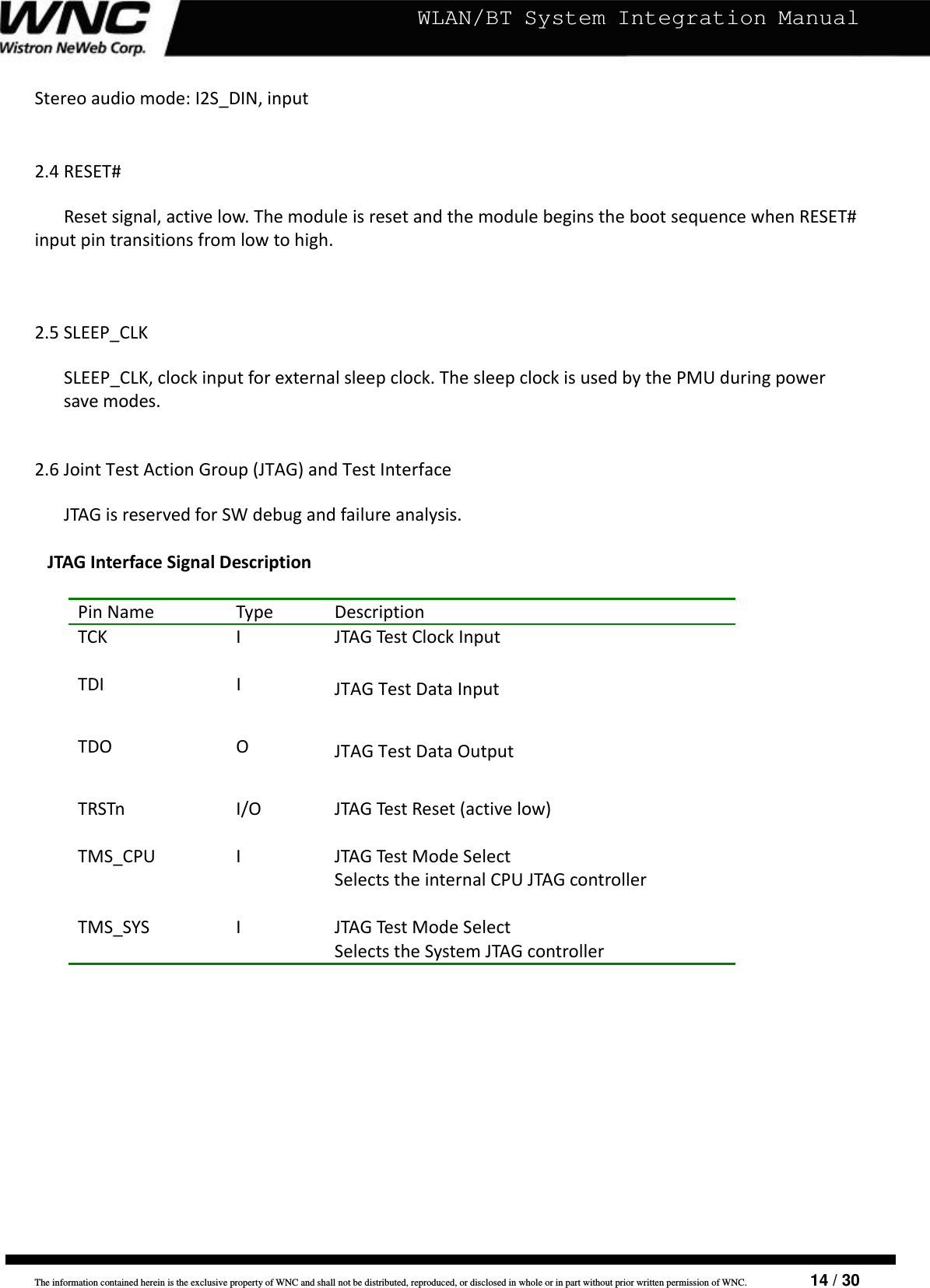
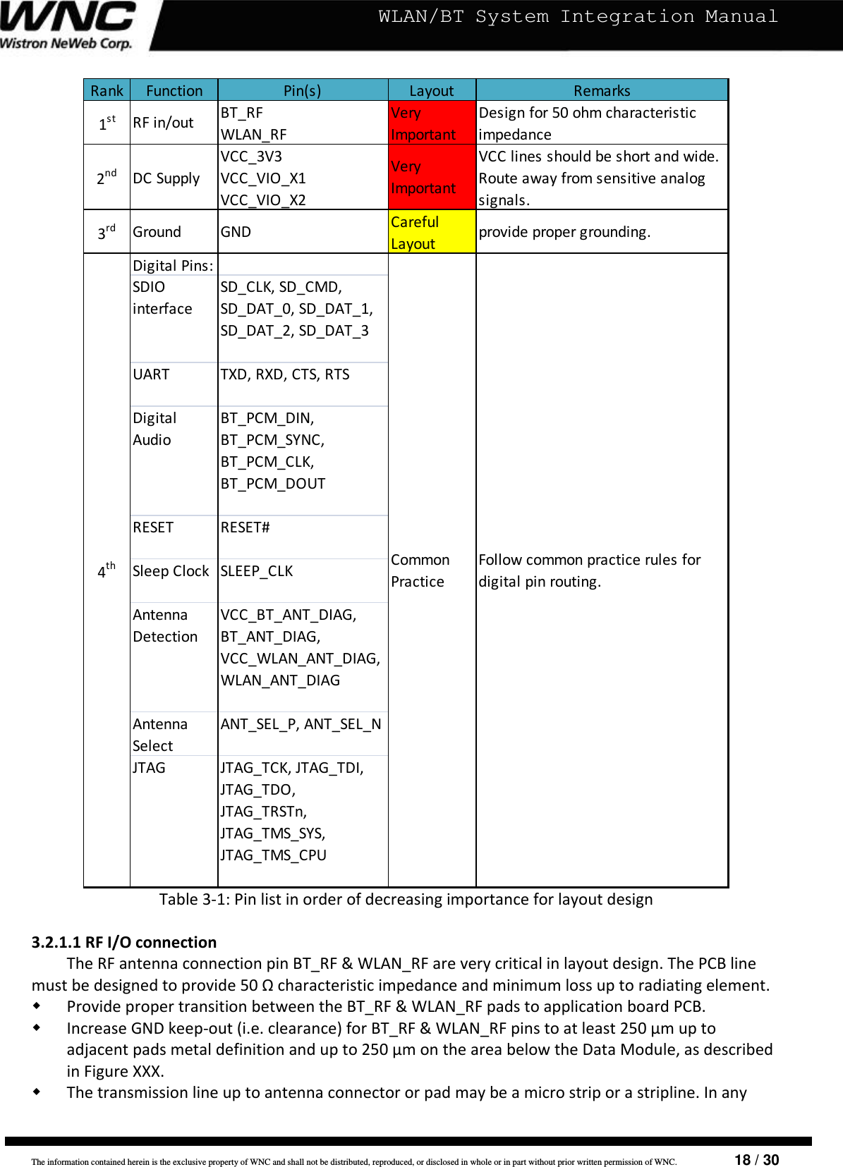
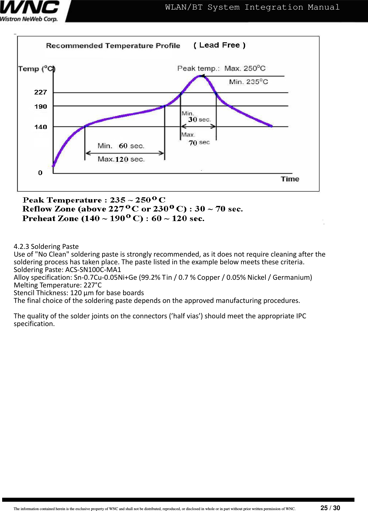
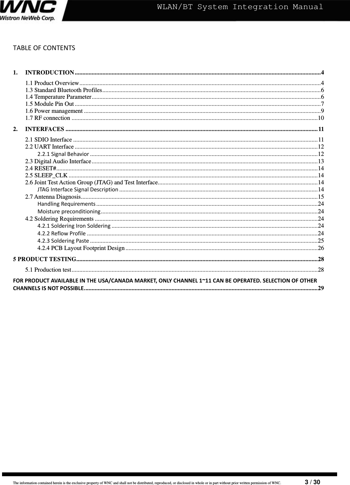
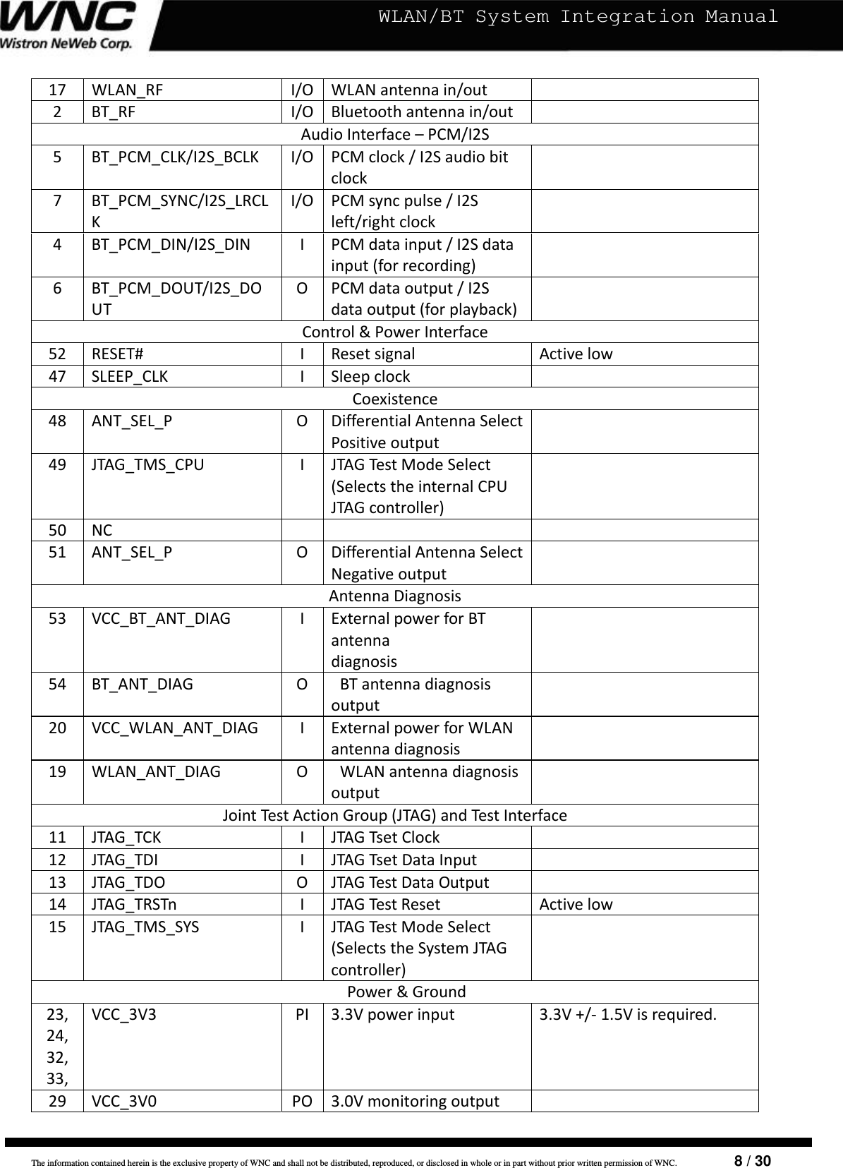
![The information contained herein is the exclusive property of WNC and shall not be distributed, reproduced, or disclosed in whole or in part without prior written permission of WNC. 17 / 30 WLAN/BT System Integration Manual3.1.2LayoutchecklistThefollowingarethemostimportantpointsforasimplelayoutcheck:□ Check50ΩimpedanceofANTline(WLAN_RF,BT_RF).□ Followtherecommendationsoftheantennaproducerforcorrectantennainstallationanddeployment.□ Ensurenocouplingoccurswithothernoisyorsensitivesignals.□ VCCline(VCC_3V3,VCC_VIO_X1,VCC_VIO_X2)shouldbewideandshort.□ RouteVCCsupplylineawayfromsensitiveanalogsignals.□ Ensurepropergrounding.□ OptimizeplacementforminimumlengthofRFlineandcloserpathfromDCsourceforVCC.3.2DesignGuidelinesforLayoutThefollowingdesignguidelinesmustbemetforoptimalintegrationofWLAN+BTmodulesonthefinalapplicationboard.3.2.1LayoutguidelinesperpinfunctionThissectiongroupsthemodulepinsbysignalfunctionandprovidesarankingofimportanceinlayoutdesign.UART_TXGNDGNDGNDUART_RXS D_ DATA[2 ]45GNDGNDVCC_1V828GNDGNDGNDGNDBT_ RFWLAN_RFBT_P CM_ DI NBT_ PCM_ CLKBT_P CM_ DO UTBT_PCM_SY NC1GNDVCC_VIO_X2GNDJTAG_TCKJTAG_TDIJTAG_TRSTnJTAG _TM S_S YSJTAG_TDO18S D_ DATA[3 ]40 3035S D_ DATA[0 ]UART_RTSSD_DATA[1]SD_CMDSD_CLKVCC_3V3VCC_3V3VCC_3V0VCC_VIO_X1GNDGNDGND27VCC_3V3VCC_3V3VCC_WLAN_ANT_DIAGGNDWLAN_ANT_DIAG25201951015SLEEP _ CLKANT_SEL _PRESETn46VCC_BT_ANT_DIAGUART_CTSBT _ANT _ DIAG5054JTAG_TMS_CPUNCANT_ SEL _NVery ImportantCareful LayoutCommon PracticeLegend :Figure3‐1:Modulepin‐outwithhighlightedfunctions](https://usermanual.wiki/Wistron-NeWeb/UWMWBT-CWM01/User-Guide-1610650-Page-17.png)