Wooyoung Telecom HL700M LCD Monitor User Manual HL700A M17
Wooyoung Telecom Co., Ltd. LCD Monitor HL700A M17
User Manual
WOO YOUNG Telecom CO.,LTD.
U s e r’s Refere n c e
FCC STATEMENT
This equipment has been tested and found to comply with the limits for a
Class B digital device pursuant to part 15 of the FCC Rules. These limits are
designed to provide reasonable protection against harmful interference in a
residential installation. This equipment generates, uses and can radiate radio
frequency energy and, if not installed and used in accordance with the
instructions, may cause harmful interference to radio communications.
However, there is no guarantee that interference will not occur in a particular
installation. If this equipment does cause harmful interference to radio or tele-
vision reception, with can be determined by turning the equipment off and on,
the user is encouraged to try to correct the interference by one more of the
following measures:
- Reorient or relocate the receiving antenna.
- Increase the separation between the equipment and receiver.
- Connect the equipment into an outlet on a circuit different from that to which
the receiver is connected.
- Consult the dealer or an experienced radio/TV technician for help.
- Only shielded interface cable should be used.
Finally, any changes or modifications to the equipment by the user not
expressly approved by the grantee or manufacturer could void the users
authority to operate such equipment.
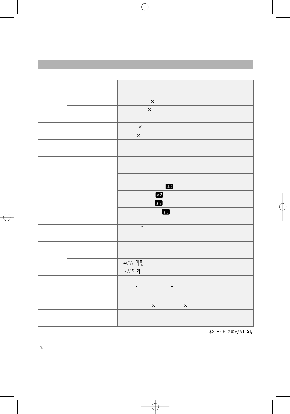
Appendix A. Specifications
The specification of this monitor is subject to be changed without notice to improve perfor-
mance.
Panel
Display
Resolution
Frequency
Sync Signal
Connectors
Tilting Degree (U/D)
Plug&Play
Power
Power Management
Environmental
Consideration
Dimensions
Weight
TFT active matrix
17 inch
337.92mm 270.336mm
0.264mm 0.264mm
8-bit (16,777,216 colors)
1280 1024@60Hz
1280 1024@75Hz
31.5~80KHz
56~75Hz
TTL, P. or N.
D-Sub 15pin connector
Speaker Input / Headphone Output (Audio Cable)
24pin Digital Cable
Audio Cable
RCA Cable
S-Video Cable
External TV Box(HL700MT Only)
-3 ~20 Degree
VESA DDC 1/2B
90~265VAC
Adapter DC 12V, 4.16A
VESA DPMS
0~40 C (32 F~104 F)
90% less
416mm(W) 409mm(H) 186mm(D)
5.2kg
3kg
Type
Pixel Pitch
Display Color
Basic
Maximum
Horizontal
Vertical
Input
Output
Consumption
Standby mode
Temperature
Humidity
Outside
Monitor
Carton
Size
1
Contents
1. Before Setting up 3
Brief Specification of LCD Monitor 3
In multimedia Model, added the below functions 3
Precautions 4
2. Items 6
3. Setting up the LCD monitor 8
Where is a good place to position the monitor? 8
Check before connecting the power cord and the signal cable !! 8
Monitor’s connectors (HL700A) 9
Monitor’s connectors (HL700M / MT) 10
Connecting Your LCD Monitor 11
Plug & Play 12
Warm-up Time 12
4. Adjusting The Monitor 13
The Function Control Buttons (HL700A) 13
How to use the Hot Key. (HL700A) 13
The Function Control Buttons (HL700M / MT) 14
How to use the Hot Key. (HL700M / MT) 14
Main OSD Menu 15
BRIGHTNESS/CONTRAST 15
2
POSITION &CLOCK/PHASE 16
COLOR 17
OSD MENU ADJUSTMENT & INPUT SOURCE 17
SETUP MENU 18
Input Source 18
Video1, Video2 19
5. Appendix 20
Appendix A. Specifications 20
Appendix B. 15-pin D-Sub Connector 21
Appendix C. 24-pin DVI Connector 22
Appendix D. DPMS Power Saving Mode 23
6. Troubleshooting 24
3
Before setting up
1
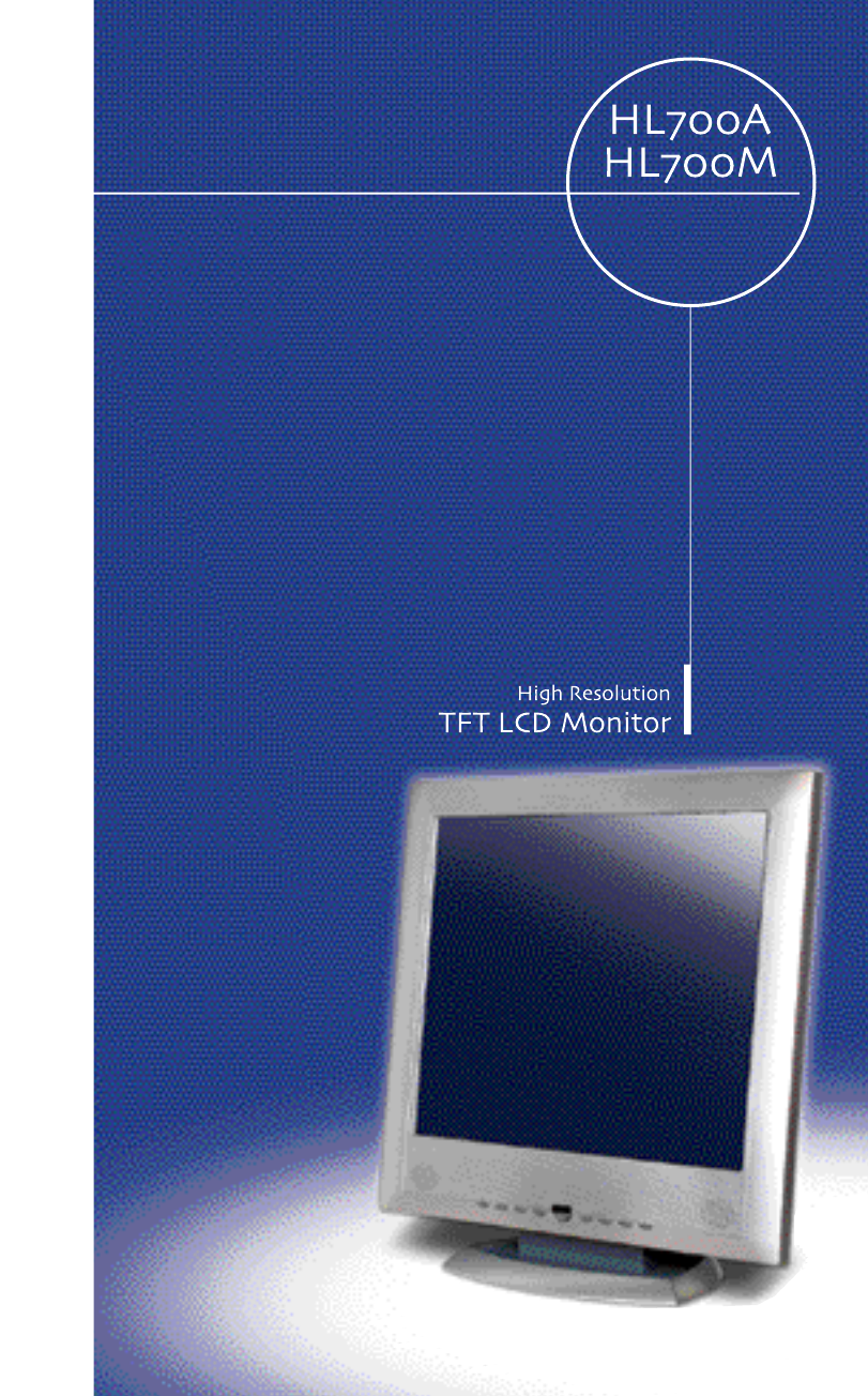
Resolution : 17.0 inch SXGA (1280 X 1024@75Hz)
Color display : 16,777,216 colors
DPMS (Display Power Management Signaling)
OSD (On Screen Display)
Auto Configuration : Hot key
Speaker [L + R : 3W + 3W = 6W (max)]
DDC 1/2B : Plug & Play
This is 17.0 inch TFT-LCD monitor. Before setting up the LCD Monitor, please read
this manual to help your understanding of the LCD Monitor.
Brief Specification of LCD Monitor
DVI(Digital Video Interface)
Composit video input
Composit Audio input
S-Video input
TV(HL700MT Only)
In Multimedia Model, added the below function:
According to PC system, DDC 1/2B may not be supported. If you meet Error
message,check your video card which compatibility with DDC. If you eant to know
more information, please contact our service center.
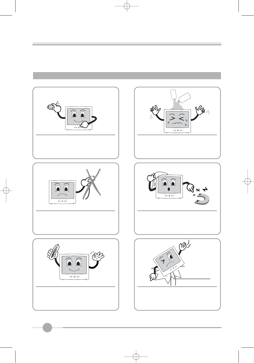
Notice
4
Do not use Ketone type material (ex.
Acetone), Ethyl Alcohol, Toluene, Ethyl
Acid or Methyl chloride, to clear the panel.
It might permanently damage the panel.
90V~265V
Check the voltage corresponds to the
local electrical supply before connecting
the AC power cord.
Never use the damaged AC power cord. Keeps it away from stoves, heaters,
fireplaces and other sources of heat
and magnets.
Don’t put your LCD monitor in a location
with high humidity and dust.
Temperature : 0~40。C
Humidity : 90% less
Place the LCD monitor on a solid sur-
face. If dropped, the screen can be
damaged easily.
Precautions
5
Don’t touch the screen with a acute nail
and pin
The LCD monitor can be damaged easi-
ly by shock.
The LCD monitor consists of electrical
devices.
If the LCD monitor is damaged, contact
immediately our service center.
Don’t use your LCD monitor under
direct sunlight.
If you don’t use the LCD monitor for a
long time, unplug the LCD monitor.
6
Items
LCD MonitorUser Manual
2
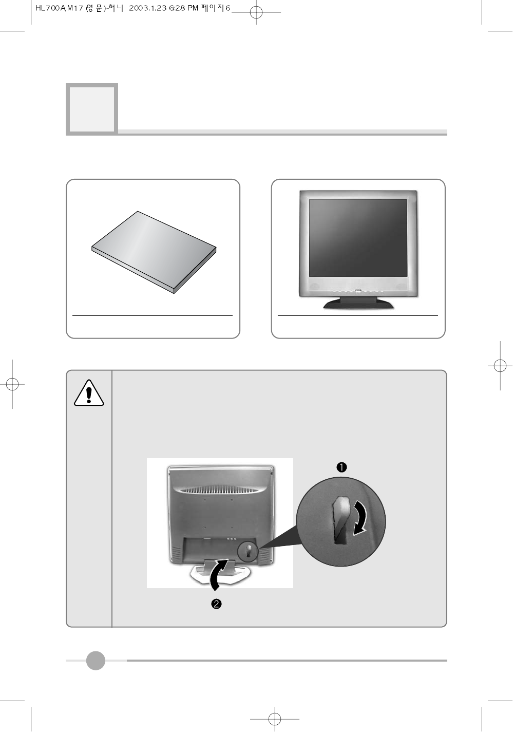
How to fold stand
If you need to fold stand for movimg. please refer to the below picture.
To fold stand, you must down lever, and you can fold stand.
Notice
7
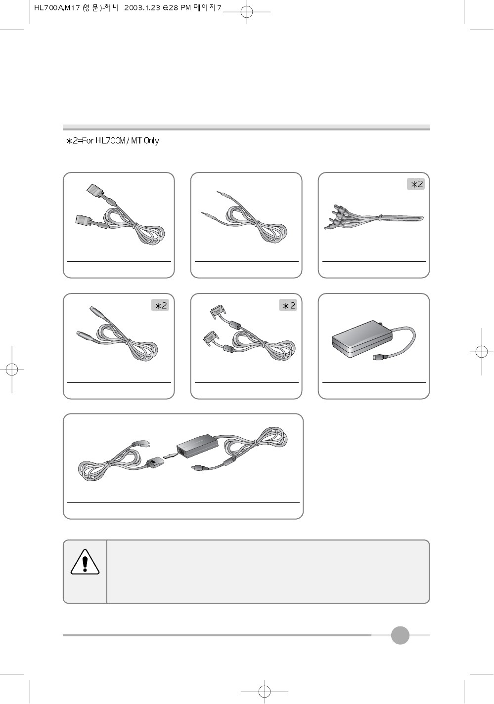
Please make sure the following items are included with your monitor.
If any items are missing, contact your dealer.
Notice
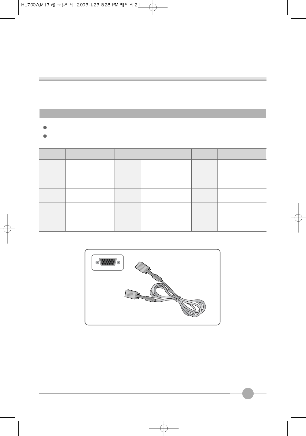
15-pin D-Sub Signal Cable
Audio Cable RCA Cable
S-Video Cable
DC Adapter
24pin Digital Cable(Option)
External TV Box (HL700MT Only)
8
Setting up the LCD monitor
3
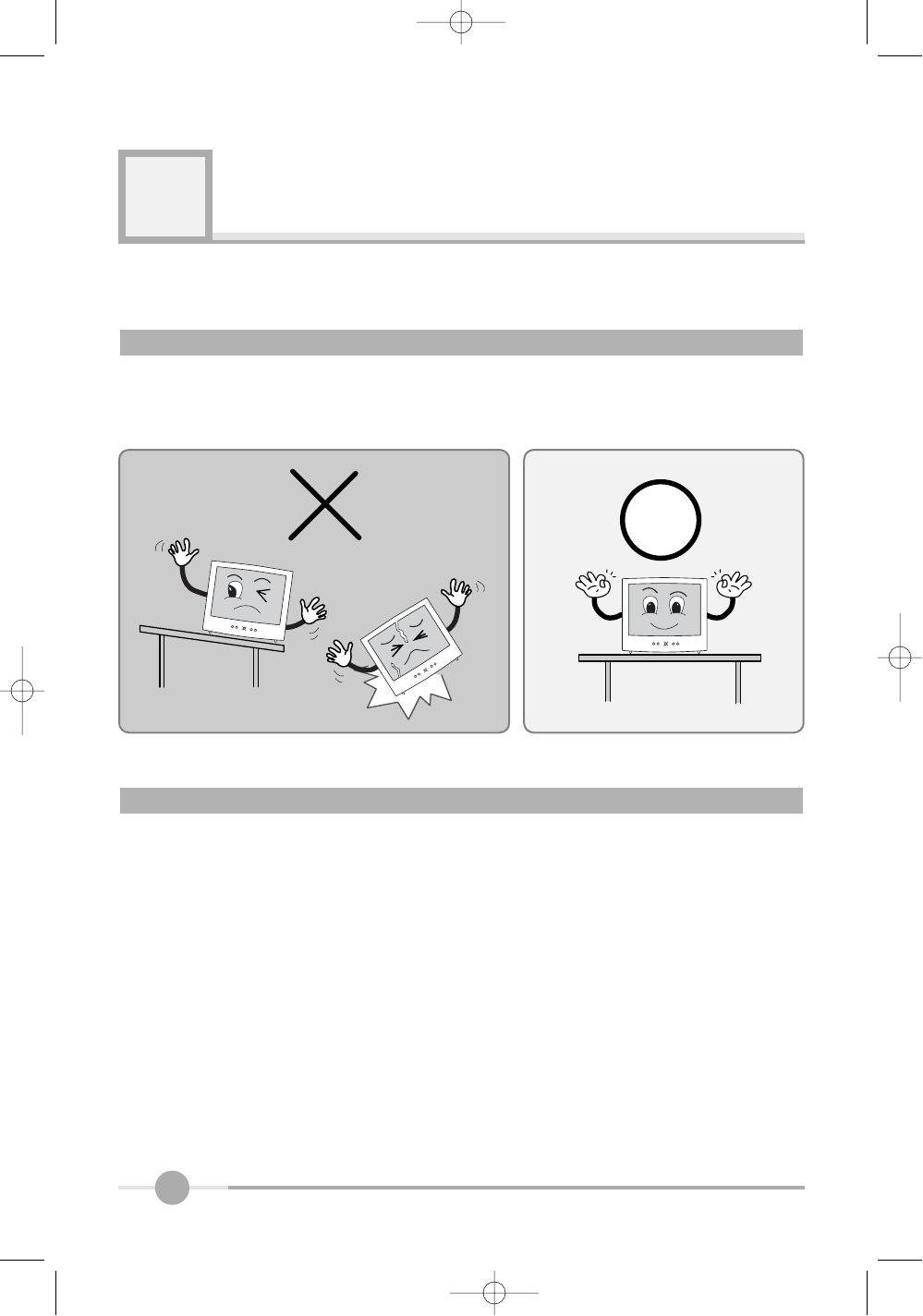
Place the LCD monitor on a solid and flat surface. If dropped, the screen can be dam-
aged easily.
Turn off the PC power before connecting the power cord and signal cable to the LCD
monitor.
Where is a good place to position the monitor?
Check before connecting the power cord and the signal cable !!
9
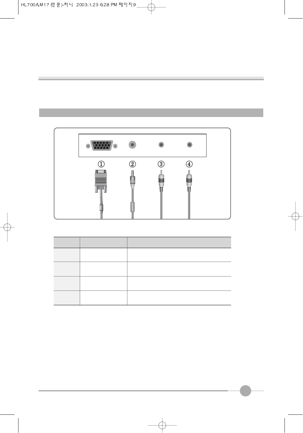
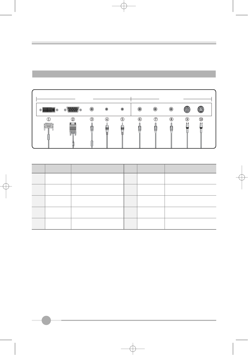
Monitor’s connectors (HL700A)
1
3
4
2
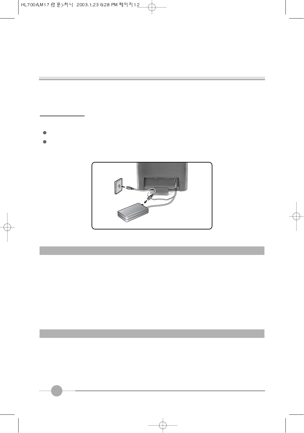
PC 15-pin D-Sub Signal Cable
DC Adaptor
Audio Cable
External Speaker
DC12V
PC AUDIO IN
SPK OUT
No. Cable connectionsName
10
PC VIDEO
1 DVI Digital Video Cable(option) 6 AUDIO(R) Audio output(R) (Red)
2PC
15-pin D-Sub Signal Cable
7 AUDIO(L) Audio output(L) (White)
3 DC12V
DC Adapter
8 VIDEO1 DVD/VCR Cable (Yellow)
4
PC AUDIO IN
Speaker Cable 9 Ext.
External TV Box (HL700MT Only)
5 SPK OUT External Speaker Cable 10 VIDEO2
S-Videl Cable
No. Name Cable connections No. Name Cable connections
Monitor’s connectors (HL700A)
11
Connecting your PC system
1. Connect the 15-pin D-Sub Signal Cable from PC to No.1.
2. If you use a speaker, connect the Audio Cable from PC to No.3.
3. If you use a headphone and earphone, connect the Headphone Cable from PC to
No.4.
Connecting Your LCD Monitor
Connecting your PC system
1. Connect the 15-pin D-Sub Signal Cable from PC to No.2.
2. If you have a DVI compliant video graphics adaptor, connect Digital Video Cable from
PC to No.1.
3. If you use a speaker, connect the Audio Cable from PC to No.4.
4. If you use a headphone and earphone, connect the Headphone Cable from PC to
No.5.
Connecting your AV(DVD, VIDEO, CAMCODER) & TV
1. Connect the DVD/VCR Cable from PC to No.6, No.7 and No.8.
2. Connect the external TV box cable to NO.9.
3. Connect the S-Video cable to NO.10.
FCC RF
INTERFERENCE STATEMENT
NOTE :
This equipment tas been tested and found to comply with the limits for a Class A digital
device, pursuant to part 15 of the FCC Rules. These limits are designed to provide
reasonable protection against harmful interference when the equipment is operated in a
commercial environment. This equipment renerates, uses, and can radiate radio frequency
energy and, if not installed and used in accordance with the instruction manual, may cause
harmful interference to redio commuications. Operation of this equipment in a residential
area is likely to cause hamful interference in which case the will be required to correct the
interference at his own expense.
For HL700A
For HL700M /MT
12
The adoption of the new VESA Plug and Play solution eliminates complicated and
time consuming setup. It allows you to install your monitor in a Plug and Play compati-
ble system without the usual hassles and confusion. Your PC system can easily identi-
fy and configure itself for use with your display. This monitor automatically tells the PC
system its Extended Display Identification Data (EDID) using Display Data Channel
(DDC) protocols so the PC system can automatically configure itself to use the flat
panel display.
All LCD monitors need time to become thermally stable whenever you turn on the
monitor after letting the monitor be turned off for a couple of hours. Therefore, to
achieve more accurate adjustments for parameters, allow the LCD monitor to be
warmed up for at least 20 minutes before making any screen adjustments.
Plug & Play
Warm-up Time
Connecting for TV
Connect the external TV Box to Monitors Ext. jack
Connect the antenna cable to the external TV Box from wall antenna jack same as the
below the picture
13
Adjusting The Monitor
4
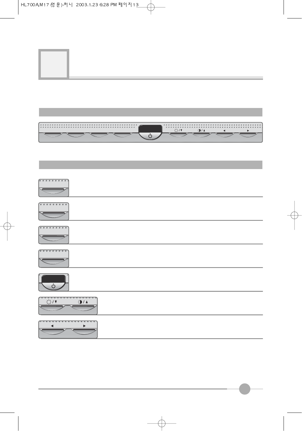
MUTE AUTO MENU SELECT VOLUME
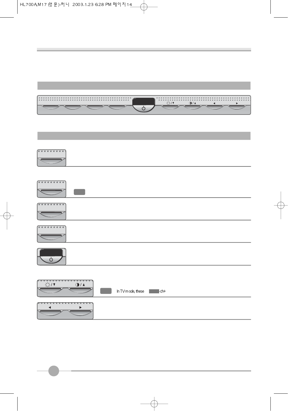
The Function Control Buttons (HL700A)
How to use the Hot Key. (HL700A)
Sound Mute On/Off button.
MUTE
You can adjust brightness or contrast as not key. When display
adjust menu, you can adjust with Left/Right button arrow button.
When you push the Left/Right button, you can adjust the
volume.
VOLUME
OSD menu On/Off button.
MENU
When you push Auto button, this will optimize image quality automati-
cally.
AUTO
Power On/Off toggle button.
Menu select button.
SELECT
14
MUTE AUTO/SELECT MENU MODE VOLUME
The Function Control Buttons (HL700M / MT)
How to use the Hot Key. (HL700M / MT)
Sound Mute On/Off button.
MUTE
You can adjust brightness or contrast as not key. When display
adjust menu, you can adjust with Left/Right button arrow button.
When you push the Left/Right button, you can adjust the
volume.
VOLUME
OSD menu On/Off button.
MENU
When you push Auto button, this will optimize image quality automati-
cally.
AUTO/SELECT
Power On/Off toggle button.
Menu select button.
MODE
Notice :
Notice : In MENU, the button is “SELECT”function
15
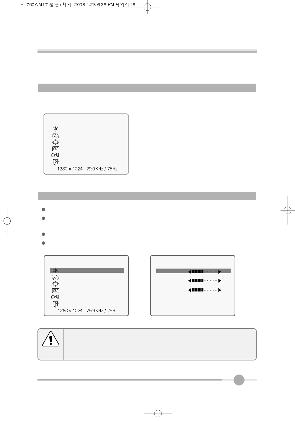
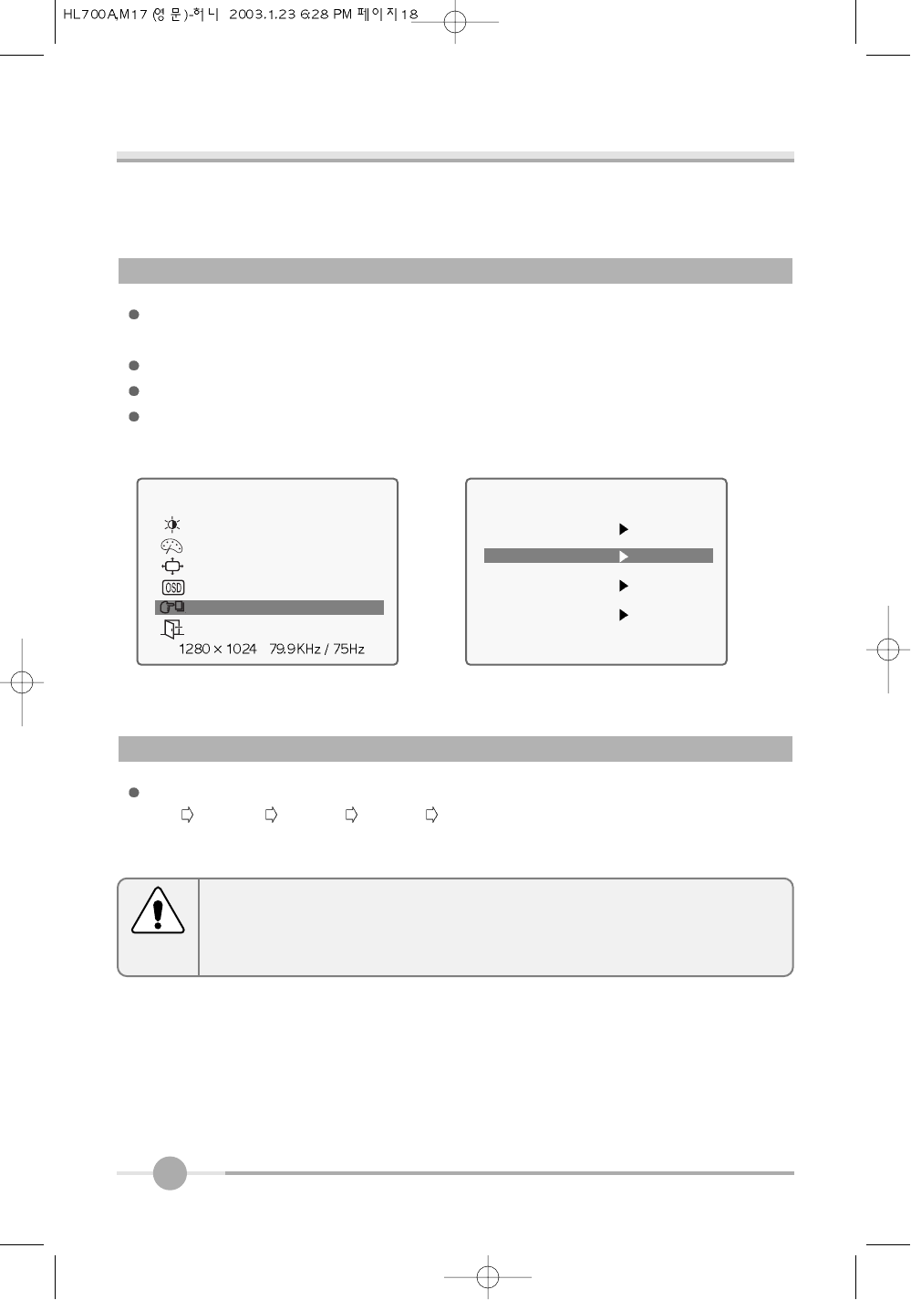
When you push the menu button, you can see below main OSD menu.
Brightness : Changes the overall light intensity of the images being displayed.
Contrast : Changes the ratio of light intensity between the brightest white and dark-
est black.
You can adjust brightness/contrast values that you want by this hot key.
Gamma : Change the gamma value.
Main OSD Menu
BRIGHTNESS/CONTRAST
MAIN MENU
BRIGHTNESS/CONTRAST
COLOR
POSITION
OSD
SETUP
EXIT
BRIGHTNESS / CONTRAST
BRIGHTNESS 50
CONTRAST
GAMMA
EXIT
Adjusting Gamma Value is useful in case of game or movie screen.
Notice
MAIN MENU
BRIGHTNESS/CONTRAST
COLOR
POSITION
OSD
SETUP
EXIT
16
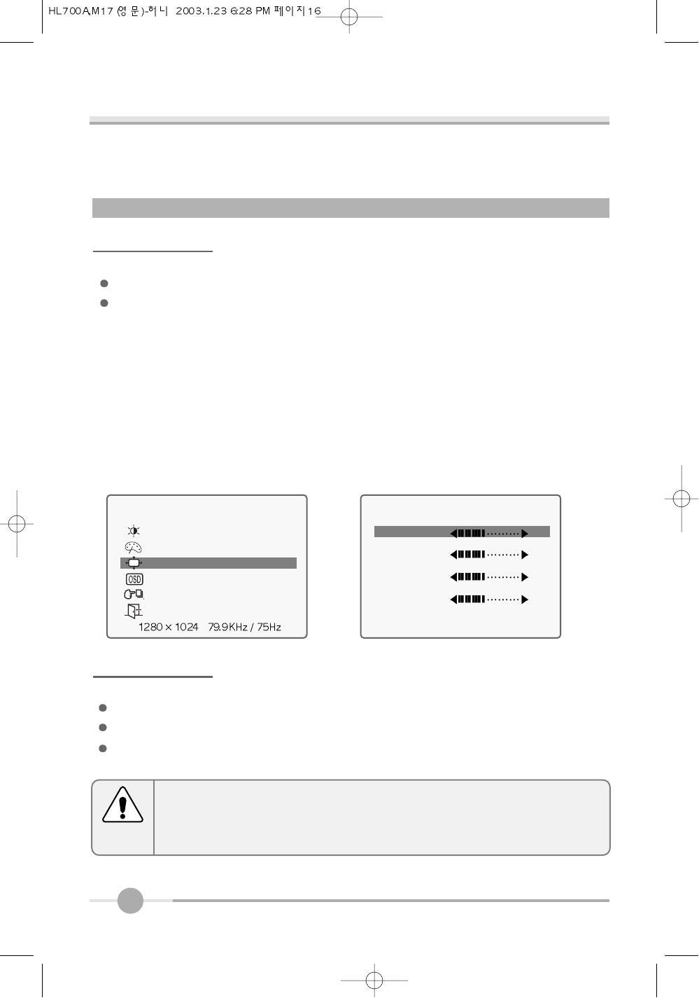
MAIN MENU
BRIGHTNESS/CONTRAST
COLOR
POSITION
OSD
SETUP
EXIT
POSITION
HORIZONTAL 50
VERTICAL
CLOCK
PHASE
EXIT
CLOCK/PHASE
When image is not clear, you can use clock/phase menu.
PHASE/ CLOCK : Although ‘Auto Adjustment’ automatically finds the optimum val-
ues of Clock and Phase parameters as well as image position, it
may be necessary for you to adjust those parameters manually.
It is recommended for you to use ‘Auto Adjustment’ first. If the
adjustment results are not satisfactory, then use Clock and
Phase adjustment features to get the best adjustment results.
Bear in mind that Clock and Phase adjustment may change the
width of the image and affect image position as well. If the image
is clear while out of center by a couple of pixels, use image posi-
tion to center the image.
POSITION & CLOCK/PHASE
POSITION
Changes the location of the image.
H-Position : Moves to the Left/Right
V-Position : Moves to the Bottom/Top
If image is not clear (noise), you can adjust Clock/Phase.
Notice
17
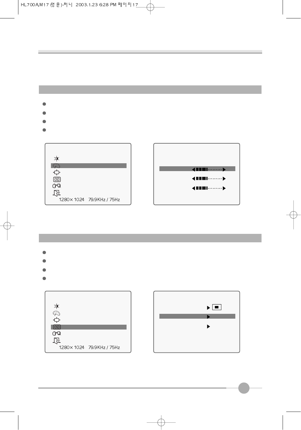
COLOR
The tone of color can be changed form bluish white to reddish white.
Color1 - Blue type
Color2 - Red type
RED, GREEN, BLUE - You can adjust red, green and blue values that you want.
MAIN MENU
BRIGHTNESS/CONTRAST
COLOR
POSITION
OSD
SETUP
EXIT
COLOR
COLOR1 COLOR2
RED 50
GREEN
BLUE
EXIT
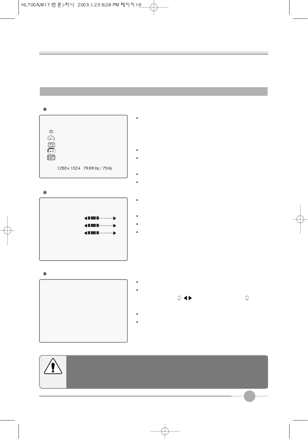
OSD MENU ADJUSTMENT & INPUT SOURCE
Sets the OSD menu display position.
OSD Position : Moves the OSD menu to the horizontal or vertical direction.
OSD TIME : Shows the OSD TIME displays from 5 to 60sec.
LANGUAGE : Select language in OSD menu.
MAIN MENU
BRIGHTNESS/CONTRAST
COLOR
POSITION
OSDT
SETUP
EXIT
OSD
OSD POSITION
OSD TIME 30 SEC
LANGUAGE ENGLISH
EXIT
18
SETUP MENU
Auto balance : Automatic adjust color (white level) for various input source’s white
level.
Input source : display input signal.
Information : display monitor’s information.
Recall : Discards current setting and replaced all paramotors with the factory
default values.
Input Source (HL700M / MT)
INPUT SOURCE : Selects input signal.
(PC DIGITAL VIDEO1 VIDEO2 TV)
MAIN MENU
BRIGHTNESS/CONTRAST
COLOR
POSITION
OSD
SETUPT
EXIT
SETUP
AUTO BALANCE SELECT
INPUT SOURCE PC
INFORMATION SELECT
RECALL SELECT
EXIT
The mode button can adjust Input Source by hot key.
In this case, the mode change time spend 2~3sec.
Notice
19
The mode button can adjust Input Source by hot key.
In this case, the mode change time spend 2~3sec.
Notice
VIDEO1, VIDEO2 (HL700M / MT)
MAIN MENU
BRIGHTNESS / CONTRAST
COLOR
CHANNEL
SETUP
EXIT
COLOR
SHARPNESS
COLOR
TINT
EXIT
BRIGHTNESS / CONTRAST : Increase or decreases the
light intensity of the screen / increase or decrease the
ratio of the light intensity between the brightest white and
the darkest black.
COLOR : Refer to below color menu.
CHANNEL : Refer to below channel menu.
(TV installation)
SETUP : Refer to OSD menu adjustment.
EXIT : Finish the current status.
SHARPNESS : Make image of the VIDEO/TV looked
sharper.
COLOR : Adjust color intensity of the VIDEO/TV.
TINT : Adjust a color tone of the VIDEO/TV.
SETUP : Refer to OSD menu adjustment.
MAIN MENU
COLOR
CHANNEL
AIR/CATV
AUTO CHANNEL
MANUAL CHANNEL
EXIT
AIR/CATV : Select AIR or CATV.
AUTO CHANNEL : Search the channel automatically.
(SELECT button button : select channel
SELECT button (ADD/DEL))
MANUAL CHANNEL : Search the channel manually.
FINE : Adjust image quality of the TV.
CHANNEL
20
Appendix
5
Appendix A. Display Modes
Mode
VGA
SVGA
XGA
SXGA
640 X 480
720 X 400
800 X 600
1024 X 768
1280 X 1024
Resolution
31.468
Horizontal
Frequency(KHz)
Vertical
Frequency(Hz)
Pixel Clock
Frequency(MHz)
Sync
Polarity(H/V)
31.468
35.000
37.500
37.879
48.077
46.875
48.363
56.476
60.023
70.087
59.940
66.670
75.000
60.300
72.188
75.000
60.004
70.000
75.029
28.322
25.175
30.240
31.500
40.000
50.000
49.500
65.000
75.000
78.750
-/+
-/-
-/-
-/-
+/+
+/+
+/+
-/-
-/-
+/+
21
Appendix B. 15-pin D-Sub Connector
Input signal : Analog RGB
15-pin D-Sub connector
15pin D-Sub Signal Cable
Pin No.
1
3
4
2
Analog Red Input
Analog Green Input
Analog Blue Input
Ground
5
Pin No.
6
8
9
7
10
DDC Ground
Signal Name
Analog Red Ground
Analog Green Ground
Analog Blue Ground
No Connect
Sync Ground
Signal Name Pin No.
11
13
14
12
15
Ground
DDC Data
Horizontal Sync
Vertical Sync
DDC Clock
Signal Name
22
Appendix C. 24-pin DVI Connector
Input signal : Digital
24-pin DVI connector
24pin Digital Cable
Pin No.
TMDS DATA2-
TMDS DATA2+
DGND
NC
Pin No.
NC
Signal Name
TMDS DATA1-
TMDS DATA1+
DGND
NC
NC
Signal Name Pin No.
TMDS DATA-
TMDS DATA+
DGND
NC
NC
DDC CLOCk +5V POWER DGND
DDC DATA AGND TMDS CLOCK+
Analog vertical Sync
NC TMDS CLOCK-
Signal Name
23
This monitor has a built-in power management system called DPMS Power Saving
Mode. This system saves energy by switching your monitor into a low-power mode
when it has not been used for a certain period of time. The available modes are “ON”,
“Standby”, “Suspend”, and “OFF”.
Appendix D. DPMS Power Saving Mode
ON
State
Stanby
mode
Stanby
mode
OFF
Active
H-sync
Inactive
Active
Inactive
Active
V-sync
Active
Inactive
Inactive
Active
RGB
Signal
Blanked
Blanked
Blanked
Power
Consumption
Under
40Watt
Less
than
5Watt
-
Recovery
Time
Green
Amber
Amber
Amber
LED Color and
Operting status
Within
2Sec
24
Troubleshooting
6
What you see
Ensure that the power cord is firmly connected and the LCD
monitor is on.
“out of range” message.
“No signal input” message.
Screen is blank and power indictor
is off.
Check the maximum resolution and the frequency of the
video adaptor.
Compare these values with the data in the Display Modes
Timing Chart.
Ensure that the signal cable is firmly connected to the PC
or video sources.
Ensure that the PC or video sources are turned on.
The image is too light or too dark. Adjust the Brightness and Contrast.
Refer to the Brightness/Contrast
The image color is not good. Adjust the Color
Refer to the Color
Image is not centered on the
screen. Executes Auto Configuration.
Screen is blank and power indicator
light is steady amber or blinks.
The monitor is using its power management system.
Move the computer’s mouse or press a key on the key-
board.
Image is not stable and may
appear to vibrate.
Check that the display resolution and frequency from your
PC or video board is an available mode for your monitor.
On your computer check : Control Panel, Display, Settings
Note : Your monitor supports multiscan display functions
within the following frequency domain:
Horizontal frequency : 31~80KHz
Vertical frequency : 56~75Hz
Maximum refresh rate : 1280 x 1024 @75Hz
Suggested Actions
WOO YOUNG Telecom CO.,LTD.
h t t p : / / w w w . w y t . c o . k r
P/N : 97E9500117