Wuerth Elektronik eiSos and Co KG F162000010 KaVo Radio 2.4 GHz Transceiver Module User Manual
AMBER Wireless GmbH KaVo Radio 2.4 GHz Transceiver Module
User Manual
Annex No.5
Technical Description
Users Manual
User instructions
ERGOcom 3
Always on the safe side.

Vertrieb / Distribution:
KaVo Dental GmbH & Co. KG
Bahnhofstraße 20
D-88447 Warthausen
Tel.: ++ 49 / 73 51 / 56 - 0
Fax: ++ 49 / 73 51 / 56 16 27
Hersteller / Manufacturer:
Kaltenbach & Voigt GmbH & Co. KG
Bismarckring 39
D-88400 Biberach

ERGOcom 3
Table of contents
Table of contents
Table of contents ............................................................................................................................................3
1 User Notes ....................................................................................................................................................5
1.1 User guidelines ........................................................................................................................................5
1.1.1 Abbreviations ..................................................................................................................................5
1.1.2 .........................................................................................................................................................5
1.2 Target audience .......................................................................................................................................6
1.3 Service .....................................................................................................................................................7
1.4 Provisions of guarantee ...........................................................................................................................8
1.5 Transport and storage ..............................................................................................................................9
1.5.1 The German packaging ordinance, 28 August 1998 ......................................................................9
1.5.2 Damage in transit ............................................................................................................................9
1.5.3 Storage .........................................................................................................................................10
2 Safety ..........................................................................................................................................................12
2.1 Description of safety instructions ...........................................................................................................12
2.1.1 Hazard warning symbol ................................................................................................................12
2.1.2 Structure .......................................................................................................................................12
2.1.3 Description of the different levels of hazard ..................................................................................12
2.2 Intended purpose ...................................................................................................................................13
2.2.1 General .........................................................................................................................................13
2.2.2 Product-specific ............................................................................................................................13
2.3 Safety instructions ..................................................................................................................................14
2.3.1 General .........................................................................................................................................14
2.3.2 Product-specific ............................................................................................................................14
3 Product description ...................................................................................................................................15
3.1 Product name .........................................................................................................................................15
3.2 ERGOcom 3 ...........................................................................................................................................16
3.3 Connections ...........................................................................................................................................17
3.4 Rating plate ............................................................................................................................................18
3.5 Technical data ........................................................................................................................................19
4 Start-up .......................................................................................................................................................20
4.1 Start-up ..................................................................................................................................................20
4.1.1 Start-up .........................................................................................................................................20
4.1.2 Start-up, radio receiving ................................................................................................................20
4.1.3 Start-up, USB drive .......................................................................................................................21
5 Operation ....................................................................................................................................................24
5.1 Operation, general .................................................................................................................................24
5.1.1 Switch on ......................................................................................................................................24
5.1.2 Standby .........................................................................................................................................24
5.1.3 OSD menu, call ERGOcom 3 .......................................................................................................24
5.1.4 OSD menu, operate ERGOcom 3 .................................................................................................25
5.1.5 Menu points ..................................................................................................................................25
5.2 Operation, no display interface (classic) ................................................................................................27
5.2.1 Operational mode .........................................................................................................................27
5.2.2 VGA OUT - set image source .......................................................................................................29
5.2.3 VIDEO OUT 1 - set image source .................................................................................................30
5.2.4 VIDEO OUT 2 - set image source .................................................................................................32
5.2.5 Generate still .................................................................................................................................33
5.2.6 Save still ........................................................................................................................................33
5.2.7 Audio signals .................................................................................................................................34
3/56

ERGOcom 3
Table of contents
5.3 Operation, with display interface (comfort/excellence) ..........................................................................35
5.3.1 Operational mode .........................................................................................................................35
5.3.2 VGA OUT - set image source .......................................................................................................37
5.3.3 VIDEO OUT 1 - set image source .................................................................................................38
5.3.4 VIDEO OUT 2 - set image source .................................................................................................40
5.3.5 Audio signals .................................................................................................................................41
5.3.6 Generate still .................................................................................................................................41
5.3.7 Save still ........................................................................................................................................42
5.3.8 Change display view .....................................................................................................................42
5.3.9 Select image .................................................................................................................................43
5.3.10 Delete image / images ................................................................................................................44
5.3.11 Change image source .................................................................................................................45
5.4 Operation, OSD menu display interface ................................................................................................46
5.4.1 Call OSD menu display interface ..................................................................................................46
5.4.2 Operate OSD menu display interface ...........................................................................................46
5.4.3 VGA main menu ............................................................................................................................47
5.4.4 VIDEO main menu ........................................................................................................................48
5.4.5 Menu point, other ..........................................................................................................................49
6 Preparation methods DIN EN ISO 17664 ..................................................................................................51
6.1 Cleaning .................................................................................................................................................51
6.1.1 Exterior cleaning by hand .............................................................................................................51
6.2 Disinfection ............................................................................................................................................52
6.3 Maintenance ..........................................................................................................................................53
7 Safety checks .............................................................................................................................................54
8 Troubleshooting .........................................................................................................................................55
9 Glossary ......................................................................................................................................................56
4/56
ERGOcom 3
1 User Notes | 1.1 User guidelines
1 User Notes
1.1 User guidelines
Prerequisite
Please read these instructions before using the product to avoid operator error and
damage.
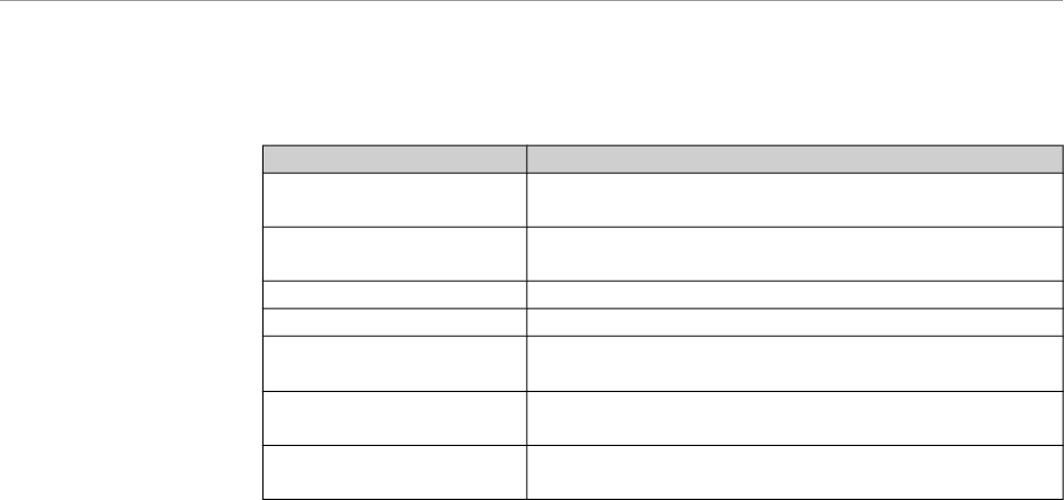
1.1.1 Abbreviations
Abbre-
viation
Meaning
UI User instructions
SI Setup instructions
EI Engineer's instructions
SFC Safety checks
IEC International Electrotechnical Commission
1.1.2
5/56

ERGOcom 3
1 User Notes | 1.2 Target audience
1.2 Target audience
This document is intended for use by dentists and other dental practice employees.
6/56

ERGOcom 3
1 User Notes | 1.3 Service
1.3 Service
Please send all questions about the product, services and maintenance to the fol-
lowing addresses.
Always quote product serial number in any correspondence.
KaVo Dental GmbH & Co. KG
After Sales Service
Bahnhofstraße 20
D-88445 Warthausen
07351-56 2700
07351-18218
kunden-service@kavo.de
www.kavo.com
KaVo Präsentations- und Servicezentrum Frankfurt (KaVo Presentation and
Service Center, Frankfurt)
Hungener Straße 6-12
60389 Frankfurt
069 - 5 97 03 -94 / 95
KaVo Präsentations- und Servicezentrum Hamburg (KaVo Presentation and
Service Center, Hamburg)
Sachsenstraße 5
20097 Hamburg
040 - 23 44 -77/ - 78
KaVo Präsentations- und Servicezentrum Düsseldorf (KaVo Presentation and
Service Center, Düsseldorf)
Kaiserswerther Straße 35
40477 Düsseldorf
0211 - 49 91 -38 / -39
KaVo Präsentations- und Servicezentrum Berlin (KaVo Presentation and Ser-
vice Center, Berlin)
Uhlandstraße 20-25
10623 Berlin
030 - 7 91 94 84
KaVo Präsentations- und Servicezentrum Leipzig-Gerichshain (KaVo Presen-
tation and Service Center, Leipzig-Gerichshain)
Zweenfurther Straße 9
04827 Leipzig-Gerichshain
03 42 92 - 7 41 -12/ -13
7/56

ERGOcom 3
1 User Notes | 1.4 Provisions of guarantee
1.4 Provisions of guarantee
The KaVo end customer guarantee for the product named in the completion certi-
ficate guarantees that the product functions correctly and that there are no faults in
the material or workmanship for a duration of 12 months following the purchase date,
according to the following conditions:
Following a reasonable complaint relating to defects or short delivery,KaVo gua-
rantee to provide a replacement or perform repairs, whichever they deem most
suitable. Claims of any other nature, damages in particular, are excluded. In case
of default and gross negligence or intent, the latter only applies if there are no com-
pelling legal provisions opposing it.
KaVo shall not be liable for defects and their consequences, which occur as a result
ofnormal wear and tear, or of improper cleaning or maintenance.
Non-observance of the operating, maintenance or connection regulations; calcina-
tion or corrosion; impurities in the air and water supply; or chemical or electrical
effects, which are non-standard or not permitted according to company regulations.
As a general rule, this guarantee does not apply to lamps, glassware, rubber parts
or the colour durability of synthetic materials.
KaVo shall not be liable for defects or their consequences if they are likely to be a
direct result of actions or modifications by a customer or third party.
Any claims arising from this guarantee can only be lodged if the completion certifi-
cate (carbon copy) has been sent in to KaVo and the operator/user is able to produce
the original.
8/56

ERGOcom 3
1 User Notes | 1.5 Transport and storage
1.5 Transport and storage
1.5.1 The German packaging ordinance, 28 August 1998
Note
Applies only to the Federal Republic of Germany.
KaVo transport packaging is disposed of and recycled by local waste management
and recycling companies under Germany's Dual System.
For more information about waste management and recycling, and for up-to-date
lists of local waste management and recycling companies, visit the following sites:
http://www.umweltdatenbank.de
http://www.quality.de
AnyKaVo transport packaging that customers return to KaVo, at the customer's own
expense, shall be forwarded to the appropriate recycling companies at no extra cost
and with no reimbursement.
1.5.2 Damage in transit
Within Germany
If the outer packaging is noticeably damaged upon delivery, the following procedure
must be adhered to:
1. The recipient must record the loss or damage on the notice of receipt. The reci-
pient and transport company employee delivering the product must both sign the
notice of receipt.
2. Leave the product and packaging in the condition they arrived in.
3. Do not use the product.
4. Report the damage to the transport company.
5. Report the damage to KaVo.
6. Under no circumstances should you return the damaged product to KaVo without
prior consultation.
7. Send the signed notice of receipt to KaVo.
If the product is damaged without there being any noticeable damage to the packa-
ging upon delivery, you must proceed as follows:
1. As soon as possible within 7 days of delivery,report the damage to the transport
company.
2. Report the damage to KaVo.
3. Leave the product and packaging in the condition they arrived in.
4. Do not use the damaged product.
Note
If the recipient fails to adhere to any of the procedures mentioned above, the da-
mage shall be considered as having arisen after delivery(pursuant to Germany's
General Terms and Conditions for Carriers (ADSp.), Article 28).
9/56
ERGOcom 3
1 User Notes | 1.5 Transport and storage
Outside Germany
Note
KaVo shall not be liable for damage caused in transit.
Check the shipment immediately upon delivery!
If the outer packaging is noticeably damaged upon delivery, the following procedure
must be adhered to:
1. The recipient must record the loss or damage on the notice of receipt. The reci-
pient and transport company employee delivering the product must both sign the
notice of receipt.
The recipient may claim damages against the transport company only on the
basis of these recorded facts.
2. Leave the product and packaging in the condition they arrived in.
3. Do not use the product.
If the product is damaged without there being any noticeable damage to the packa-
ging upon delivery, you must proceed as follows:
1. As soon as possible within 7 days of delivery,report the damage to the transport
company.
2. Leave the product and packaging in the condition they arrived in.
3. Do not use the damaged product.
Note
If the recipient fails to adhere to any of the procedures mentioned above, the da-
mage shall be considered as having arisen after delivery(pursuant to the
Convention on the Contract for the International Carriage of Goods by Road (CMR)
Chapter V Article 30).
1.5.3 Storage
Note
Save packaging in case product requires sending away for servicing or repairs..
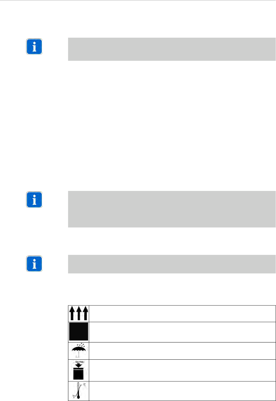
The symbols printed on the outer packaging apply to transportation and storage;
their meanings are as follows:
Keep upright in transit; this way up!
Handle with care
Keep dry
10/56
ERGOcom 3
1 User Notes | 1.5 Transport and storage
Stacking limitation.
Temperature limitations.
11/56

ERGOcom 3
2 Safety | 2.1 Description of safety instructions
2 Safety
2.1 Description of safety instructions
2.1.1 Hazard warning symbol
Hazard warning symbol
2.1.2 Structure
DANGER
The introduction describes the type and source of the danger.
This section shows what could happen if the instructions are not followed.
▶ The optional action shows what measures to take to avoid danger.
2.1.3 Description of the different levels of hazard
To avoid personal and material injury, safety instructions within this document are
classified into three levels of hazard.
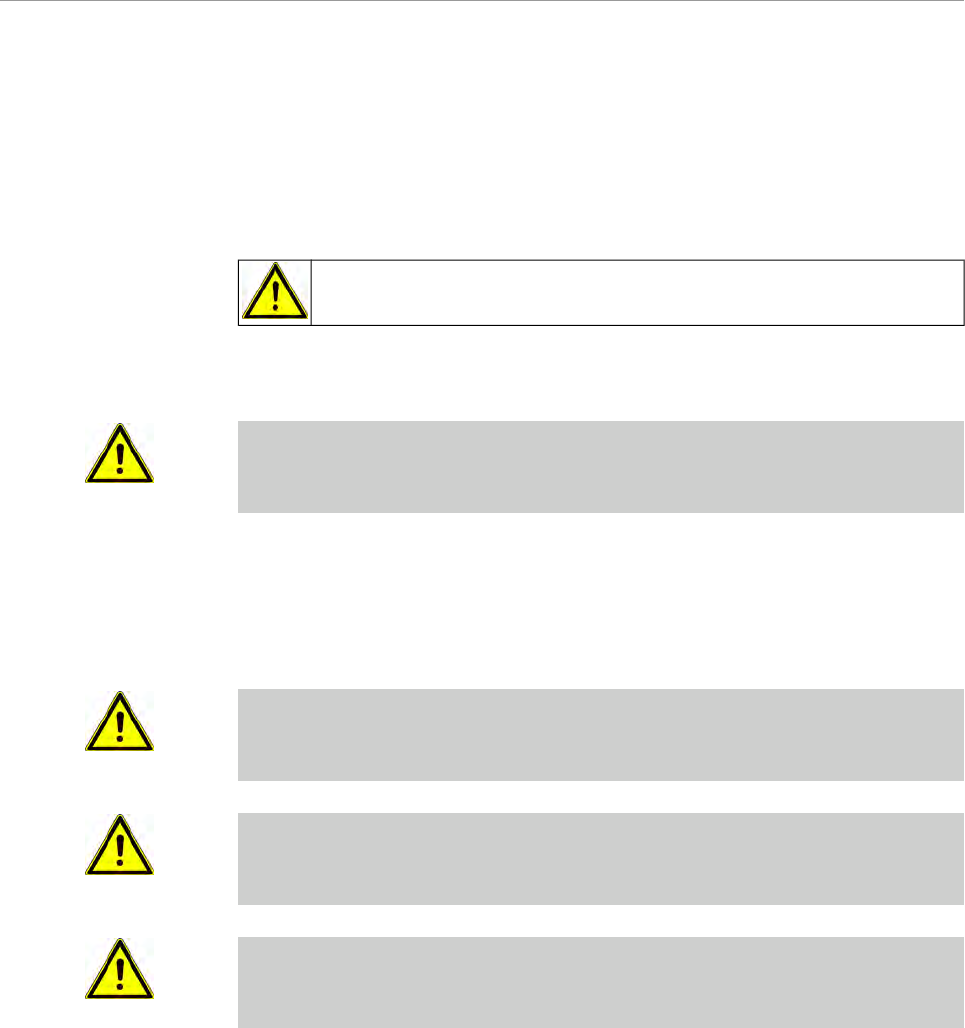
CAUTION
CAUTION
Indicates a potentially dangerous situation which could result in material damage,
minor personal injury or non-severe personal injury.
WARNING
WARNING
Indicates a potentially dangerous situation which could result in fatal injury or se-
vere personal injury.
DANGER
DANGER
This is the highest level of hazard. It indicates an imminently dangerous situation
which could result in fatal injury or severe personal injury.
12/56

ERGOcom 3
2 Safety | 2.2 Intended purpose
2.2 Intended purpose
2.2.1 General
The operator is required to make sure that the device is in a fully functional and safe
condition before commencing use.
During use, the handler must comply with state stipulations; in particular:
▪ the industrial safety regulations that are in place.
▪ the regulations that are in place for the prevention of industrial accidents.
The appropriate, comprehensive guidelines for this product and/or national laws,
national regulations and technlogical rules for starting up and operating have to be
applied and fulfilled in line with the specified, intended purpose of the KaVo product.
Note
It is mandatory that country-specific regulations be adhered to during final decom-
missioning of the KaVo product.
Should you have any questions relating to the proper disposal of the KaVo product,
please contact your nearestKaVo office.
2.2.2 Product-specific
TheERGOcom 3 shows the multimedia content of external image and audio
sources.
In a dental practice outside of the patient environment and together with
aKaVo Display , it corresponds to a medical product of protection class 1.
13/56
ERGOcom 3
2 Safety | 2.3 Safety instructions
2.3 Safety instructions
2.3.1 General
WARNING
Injuries or harm caused by damaged functional components
Damaged functional components can cause personal harm or injury.
▶ If functional components are damaged: Stop work,remedythe problem or inform
the service engineer.
CAUTION
Malfunction due to electromagnetic fields
This product meets all the requirements that are in effect relating to electromagnetic
fields. Due to the complex interference between mobile phones and medical devi-
ces, it is not, however, possible to completely exclude the possibility of the product
being affected by a functioning mobile phone.
▶ Refrain from using mobile phones in the practice and clinic area!
▶ Turn off electronic equipment, such as data storage, hearing aids etc, du-
ringoperation !
CAUTION
Risks caused by electromagnetic fields
Electromagnetic fields may interfere with the functions of implanted systems (such
as pacemakers).
▶ Consult the patient before treatment!
This KaVo product is not permitted for use in areas where there is a risk of explosion.
The following individuals are authorised to repair and maintain the KaVo product:
▪ Engineers from KaVo offices.
▪ Engineers working for KaVo authorised dealers, specially trained by KaVo.
▪ Independent engineers specially trained by KaVo.
2.3.2 Product-specific
CAUTION
Risk of injury due to electric shock
Electric shock
▶Remove bus covers only when ERGOcom 3 is switched off.
▶ Check the additionally connected cable at earthing connection M . R = < 0.1 Ohm
▶ Observe standards EN 60601-1-1, IEC 950, EN 550022 and EN 550024 in
combination with compatible displays.
▶ In the case of installation in rooms used for medical purposes, this must be
designed in accordance with DIN/VDE 0100-710 (erection of low voltage
systems).
▪ Do not place any additional portable multiple sockets on the floor.
▪ Do not connect any additional portable multiple sockets or extension cables to
the system.
▪ Do not connect any electrical equipment that is not part of the system.
14/56
ERGOcom 3
3 Product description | 3.1 Product name
3 Product description
3.1 Product name
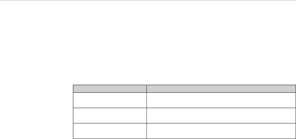
ERGOcom 3 is supplied in classic, comfort and excellence models. These models
differ with regard to the components built in, among other things.
Model Components
classic No display interface
No radio master (ERGOremote)
comfort With display interface
No radio master (ERGOremote)
excellence With display interface
With radio master (ERGOremote)
Every component can be individually upgraded. This is why operation is structured
not by the models, but by the integrated components.
15/56
ERGOcom 3
3 Product description | 3.2 ERGOcom 3
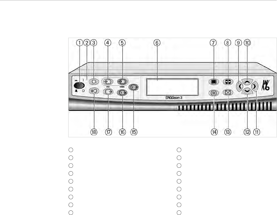
3.2 ERGOcom 3
1
Main switch
10
Navigation up
2
Standby LED, blue
11
Navigation right
3
Standby
12
Navigation down
4
Button, VGA In 1 / In 2
13
Delete image / images
5
Button, Video Camera / In 2 / In 3
14
Freeze
6
Status display
15
Button, Video Out 2
7
OSD menu
16
Button, Video Out 1
8
Quad mode
17
Button, VGA Out
9
Navigation left
18
Channel Selection/Learn Channel
Mode
16/56
ERGOcom 3
3 Product description | 3.3 Connections
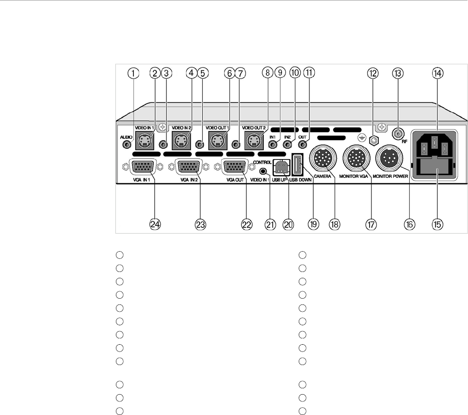
3.3 Connections
1
Audio In 1
13
Aerial connection
2
Video In 1
14
Mains connection
3
Audio In 2
15
Mains fuse
4
Video In 2
16
Power supply, monitor
5
Audio Out 1
17
Display 1 connection
6
Video Out 1
18
Camera connection
7
Audio Out 2
19
USB downstream
8
Video Out 2
20
USB upstream
9
Audio VGA In 1
21
Camera cradle / footswitch control,
Video In 1
10
Audio VGA In 2
22
VGA Out
11
Audio VGA Out
23
VGA In 2
12
Earthing point
24
VGA In 1
17/56
ERGOcom 3
3 Product description | 3.4 Rating plate
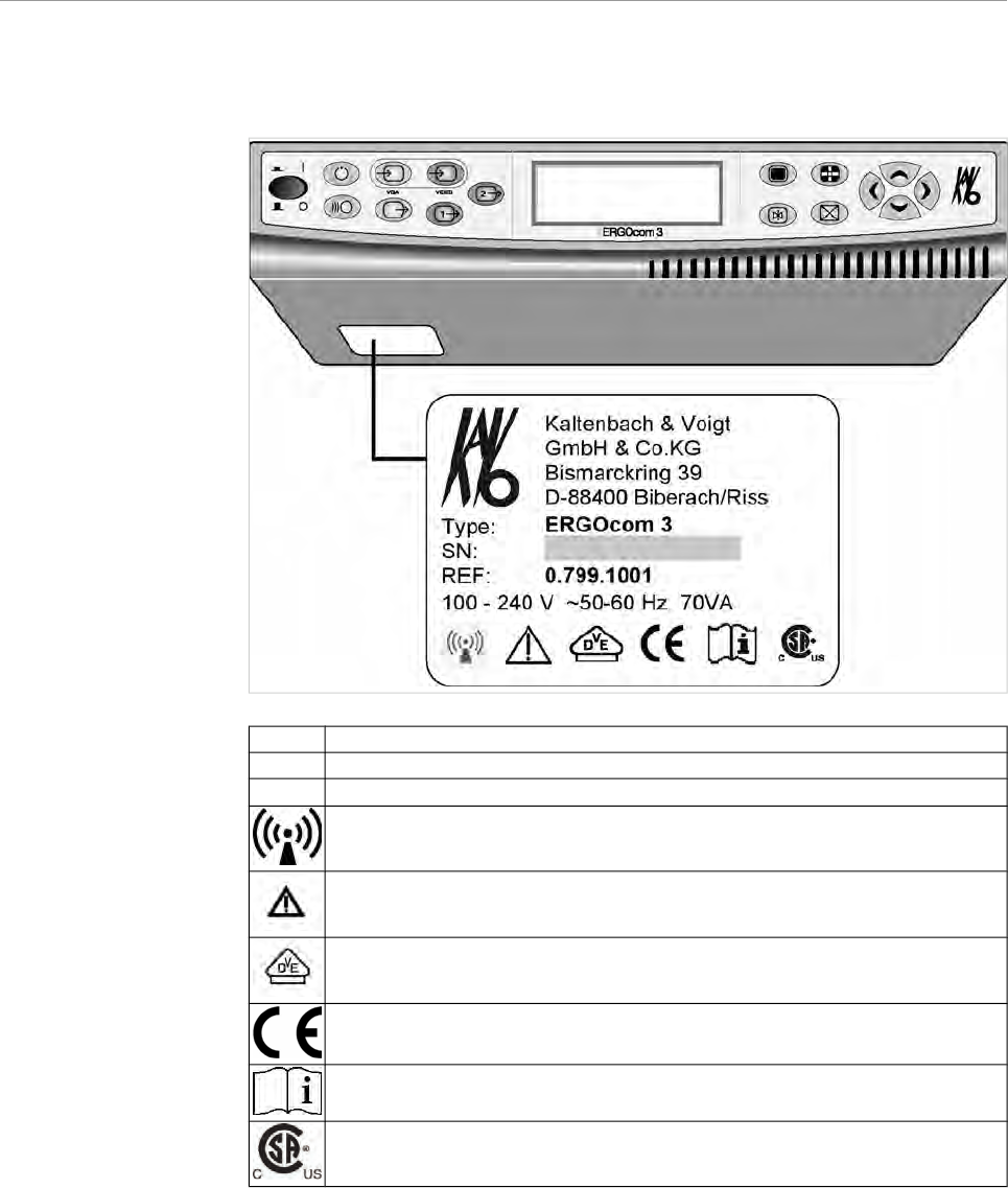
3.4 Rating plate
SN: Serial number
REF Material number
Type: Device typeERGOcom 3
HF emission
Note: consult accompanying documents.
VDE identification
CE identification
Consult instructions for use
CSA identification
18/56

ERGOcom 3
3 Product description | 3.5 Technical data
3.5 Technical data
ERGOcom 3
Weight 3 kg
Housing dimensions
Width 260 mm
Depth 260 mm
Height 46.5 mm
Electricity supply
AC voltage 100 -240 V
Rated frequency 50 - 60 Hz
Power consumption 70 VA
Ambient conditions
Permissible operating temperature 0 - 40° C
Connection of interoral camera
Type BF
Compatible displays
Max. power consumption 35 VA
19/56
ERGOcom 3
4 Start-up | 4.1 Start-up
4 Start-up
4.1 Start-up
4.1.1 Start-up
CAUTION
Malfunction due to incorrect use
An increase in operating temperature due to poor ventilation can lead to malfunc-
tion or failure.
▶ Do not set up near to a heat source.
▶ Do not cover the product's vents. A minimum gap of 50 mm must be left in front
of and behind the unit.
▶ Operate the product only when it is horizontal.
▶Connect theERGOcom 3 to a properly earthed power source that is protected by
a fuse.
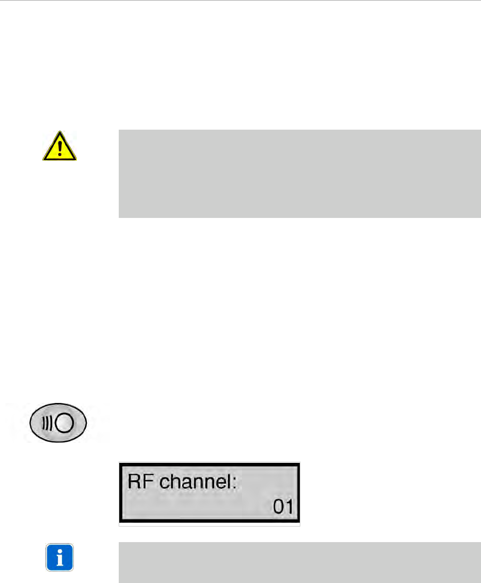
4.1.2 Start-up, radio receiving
Select channel
Here, up to 38 channels can be set. A channel determines the assignment of a
specific ERGOremote to a specific ERGOcom 3.
Here, it is expedient to select a channel corresponding to the treatment room: e.g.
channel 1 is used for treatment room 1.
▶ Hold down the Channel Selection / Learn Channel Mode button for < 2 seconds.
The channel selected appears on the status display.
Note
If there is no input for 8 seconds, the ERGOcom 3 switches back to operational
mode.
20/56
ERGOcom 3
4 Start-up | 4.1 Start-up
▶ Select the required channel using navigation.
Note
If there is no input for 8 seconds, the ERGOcom 3 switches back to operational
mode.
This saves the last setting on the status display.
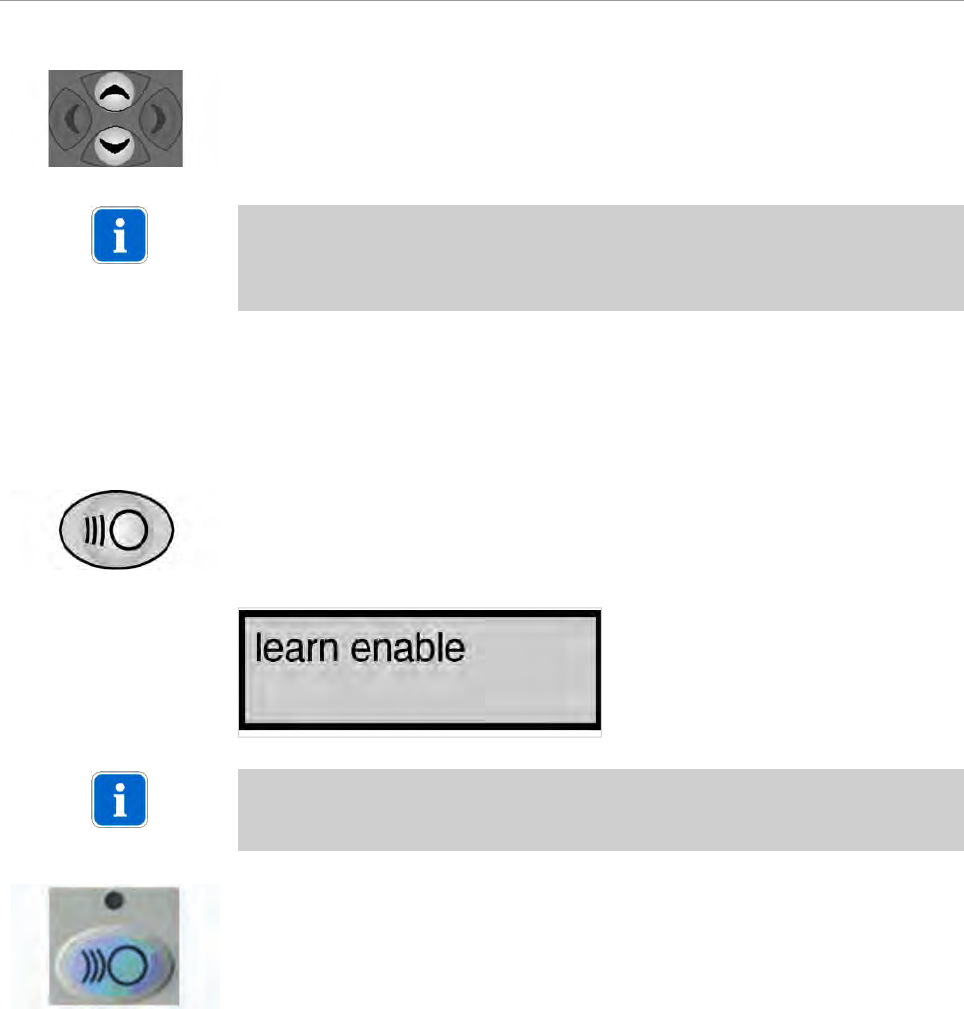
Learn channel
The ERGOremote 's radio code is synchronised with the channel configured
onERGOcom 3 .
▶Hold down the Channel Selection button on ERGOcom 3 for more than 2 se-
conds.
Learn Channel Mode appears on the status display.
Note
If the channels do not synchronise within approx. 30 seconds, ERGOcom 3 swit-
ches back to operational mode.
▶Hold down the Wake Up/Learn button on the ERGOremote for more than 3 se-
conds.
The green LED will be lit for 3 seconds to show that synchronisation is complete.
The green LED will flash to indicate that radio communication has not been set up.
4.1.3 Start-up, USB drive
TheERGOcom 3 with a display interface (equivalent to comfort or excellence level)
has a built-in USB 2.0 drive. This drive shares volatile and non-volatile memory.
The non-volatile memory then retains the information when the ERGOcom 3 is
switched off. The logos are stored here automatically.
The images are automatically stored in the volatile memory. When the
ERGOcom 3 is switched off, these images are deleted.
See also: 5.3.6 Generate still, Page 41
The images contain the following name syntax: Bildxx_y.bmp.
21/56
ERGOcom 3
4 Start-up | 4.1 Start-up
▪ xx = image number 01 to 99
▪ y = image number 1 to 4
A maximum of 8 images may be saved. When a ninth image is saved, image 1 is
automatically overwritten.
A KaVo company logo is stored on the USB drive at the time of delivery.
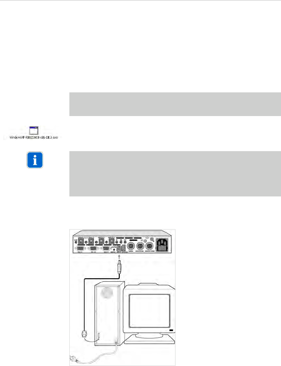
Connect PC
Prerequisite
● Windows XP (Service Pack 1) or Windows 2000 must be installed on the PC.
● The PC must have a free USB 2 interface.
▶ Install Windows patch.
Note
When installing theKaVo Device Interface System (using the enclosed CD), the
USB patch is installed automatically.
If the KaVo Device Interface System is not installed, the USB patch can be in-
stalled later from the CD D:\WINXP or downloaded and installed from the Microsoft
homepage www.microsoft.com .
▶Insert the USB cable to the ERGOcom 3 and the PC.
The connection is made between the USB drive and the PC.
Install own logo/image
▶Convert the logo/image into a 720 x 576 dpi image format using image processing
software.
22/56

ERGOcom 3
4 Start-up | 4.1 Start-up
▶ Save this logo/image in bitmap format, giving it the filename USERLOGO.bmp.
▶ Copy the file USERLOGO.bmp to the USB drive using the drag&drop function.
The USB drive reports to the PC using the name ERGOCOM3.
Note
The ERGOcom 3 must not be switched off during transfer of the image (takes
approx. 20 seconds).
You can set which logo/image is to be displayed in the OSD menu display interface.
See also: 5.4.5 Menu point, other, Page 49
23/56
ERGOcom 3
5 Operation | 5.1 Operation, general
5 Operation
5.1 Operation, general
5.1.1 Switch on
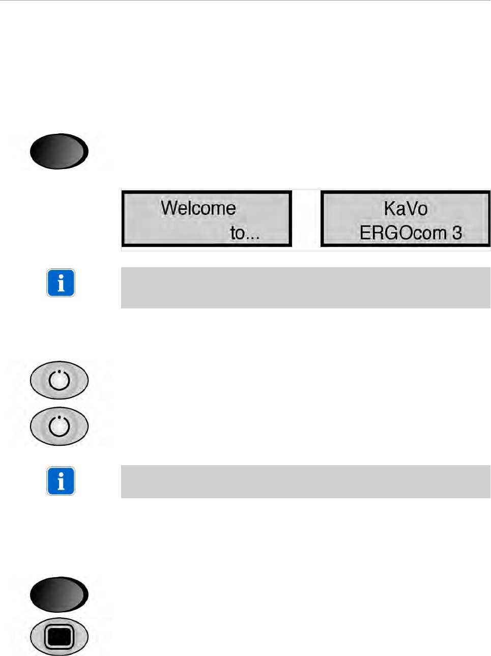
▶ Switch on main switch.
These indicator lamps appear on the status display after open-shop testing:
Note
If the device is ready for operation, the current monitor image source is shown in
the display.
5.1.2 Standby
▶ Press the standby button.
The standby LED lights up (blue).
The status display and display are switched off and all device settings are retai-
ned.
▶ Press the standby button once again to leave Standby mode.
Note
This energy saving mode extends the service life of the status display and display.
5.1.3 OSD menu, call ERGOcom 3
In this menu, all settings can be defined for operation of the product.
▶ Switch on main switch.
▶While the status display shows "ERGOcom 3", activate the OSD menu until the
first menu point appears.
The OSD menu ERGOcom 3 is divided into 7 menu points:
▪ Interface/wlink
▪ Display-Format
▪ RFpower
24/56
ERGOcom 3
5 Operation | 5.1 Operation, general
▪ System camera
▪ Camera holder
▪ USBpict.store
▪ Store format
▪ Mouse Z-Axis
▪ Firmware version
▪ Factory reset?
Note
The last 6 menu points are reserved for engineers.
▶ Press the OSD menu button once again in order to return to operationalmode.
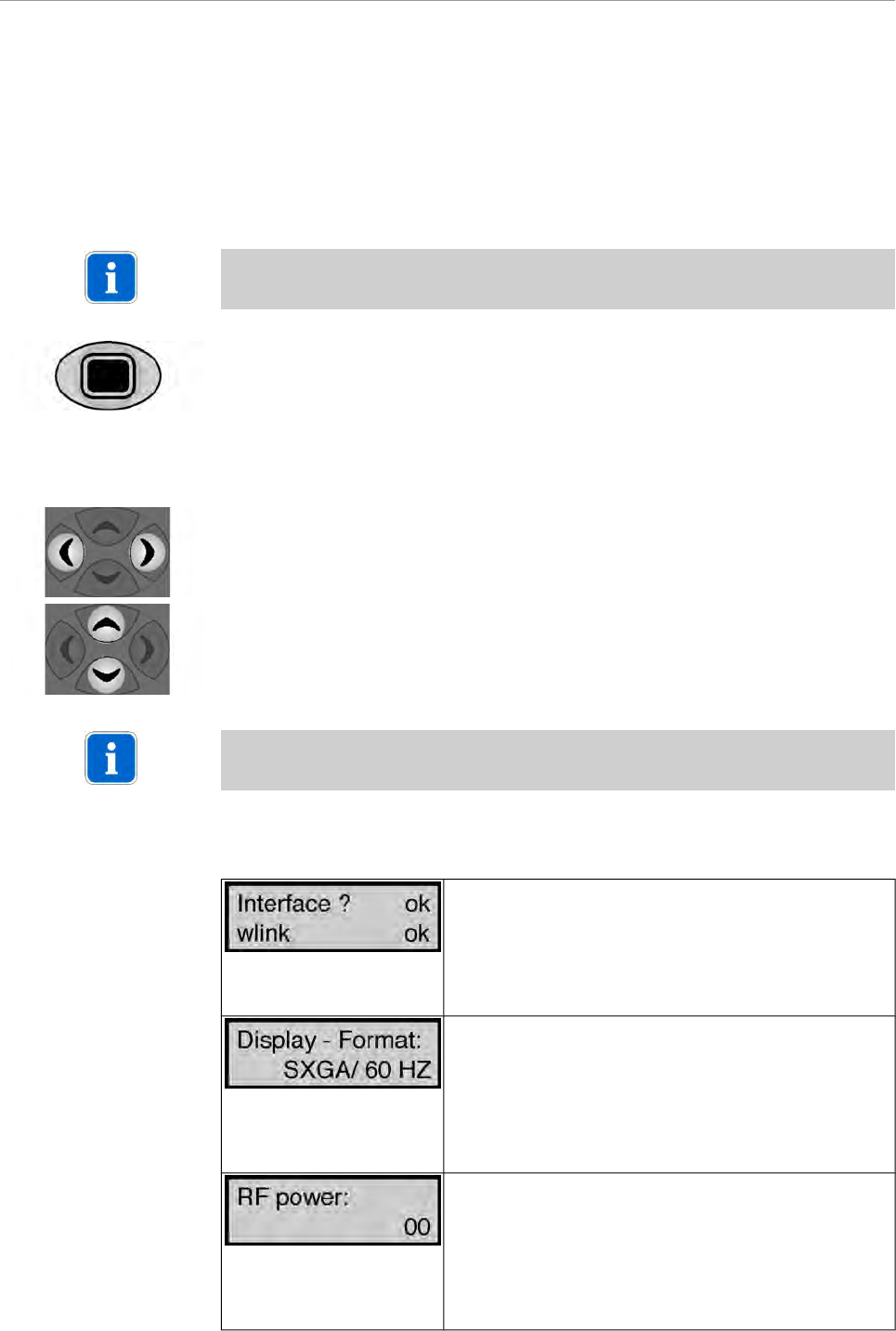
5.1.4 OSD menu, operate ERGOcom 3
▶ Select the required menu point using navigation.
When you leave a menu point, its status display will be saved automatically.
▶ Select the required setting using navigation.
Note
If there are no options available for a menu point, this navigation offers no functions.
5.1.5 Menu points
Interface? Represents component display interface
Material number 1.002.9482.
wlink represents component radio master
Material number 1.003.1318.
OK represents the installation of the relevant option.
Missing components can be added at any time.
Setting of resolution and image frequency for the dis-
play.
SXGA/50 Hz or SXGA/60 Hz is 19" (1280 x 1024 dpi)
XGA/50 Hz or XGA/60 Hz is 15" (1024 x 768 dpi)
To ensure optimum image display quality, the same
display size (15" or 19") is to be used both in the cabinet
area and on the treatment device.
00 is the default setting for 0 dBm transmitting power.
At the same time, this is the maximum permitted trans-
mitting power in the USA.
01 represents 6 dBm transmitting power. This is the
maximum permitted transmitting power in Europe. If
the transmitting power is not reliably sufficient, the
transmitting power can be increased using this.
25/56
ERGOcom 3
5 Operation | 5.1 Operation, general
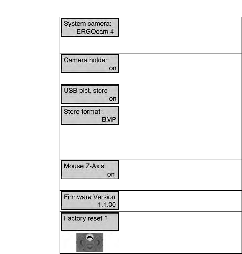
Various setting parameters for image functions are of-
fered on account of the various technical systems in the
intraoral cameras ERGOcam 3 and ERGOcam 4 offe-
red by KaVo. For optimum setting, the KaVo intraoral
camera built into the treatment device should be se-
lected here.
On: When the internal / external camera is taken out of
the holder, the camera image is automatically dis-
played on the monitor.
Off: Automatic operations are not available. The came-
ra image has to be selected manually.
On: When saving in Video mode, the images are saved
to the USB drive ERGOCOM3.
Off: Nothing is saved to the USB drive ERGOCOM3.
Determining the image format in which the images are
to be saved to the USB drive.
BMP stands for bitmap and is supported by all popular
image processing programs. The current YUV format
is converted to BMP beforehand (save time approx. 8
seconds).
YUV stands for video format and is supported by only
a few programs. However, this format is saved consi-
derably more quickly (save time approx. 2 seconds).
Here, whenERGOremote is used, the use of the Z-Axis
of the joystick is determined.
On: Clicking / double-clicking possible with the joystick.
Off: Clicking / double-clicking not possible with the joy-
stick.
Display of Firmware version number of ERGOcom 3
Mainboard.
Reset all menu points to factory settings.
CAUTION: VGA IN, VGA OUT, VIDEO IN and VIDEO
OUT will also be reset to factory settings if you select
this command.
The factory settings are restored using Navigation up.
26/56
ERGOcom 3
5 Operation | 5.2 Operation, no display interface (classic)
5.2 Operation, no display interface (classic)
Equivalent to ERGOcom 3 , classic level.
In all subsequent descriptions, please note the following: to view the selected option
on Display 1, the relevant source must be active.
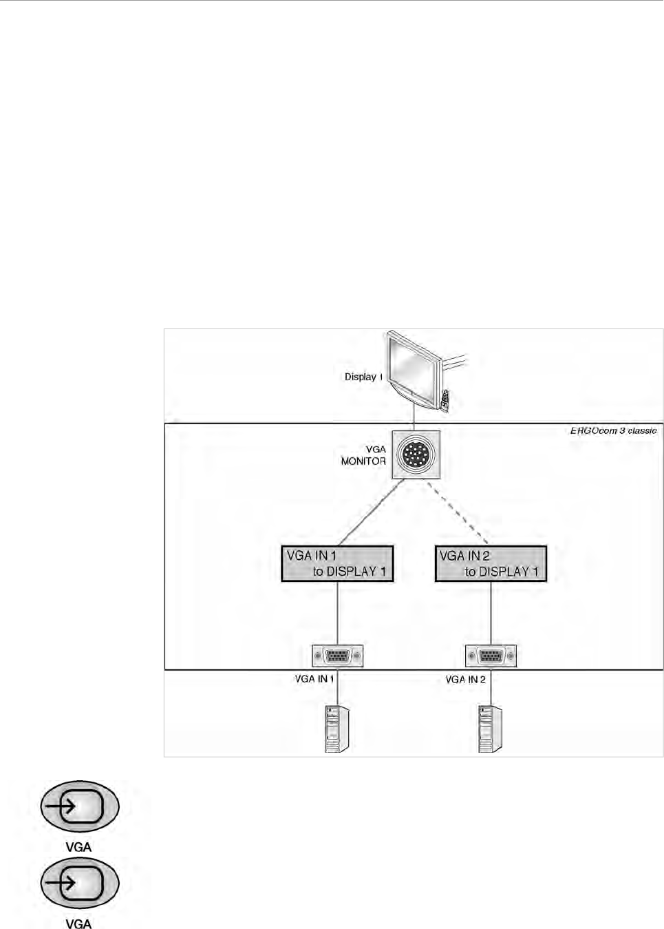
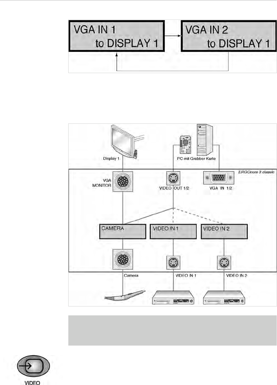
5.2.1 Operational mode
In operational mode, it is possible to switch between VGA or VIDEO image sources,
including audio, shown on KaVo Display 1.
VGA IN - set image source
▶ Press the VGA IN button.
If a VIDEO image source was selected before, the last VGA IN image source
selected will be shown in the status display.
▶ Select the required VGA input by pressing the VGA IN button.
27/56
ERGOcom 3
5 Operation | 5.2 Operation, no display interface (classic)
See also:
5.4.5 Menu point, other, Page 49
VIDEO IN - set image source
Prerequisite
● A grabber card has to be installed in the PC in order to show video sources on
Display 1.
● VIDEO OUT 1 or VIDEO OUT 2 has to be connected to the grabber card.
▶ Press the VIDEO IN button.
If a VGA image source was selected before, the last VIDEO IN image source
selected will be shown in the status display.
28/56
ERGOcom 3
5 Operation | 5.2 Operation, no display interface (classic)
▶ Select the required VIDEO input by pressing the VIDEO IN button.
See also: 5.4.5 Menu point, other, Page 49
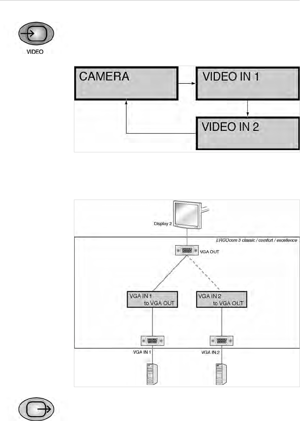
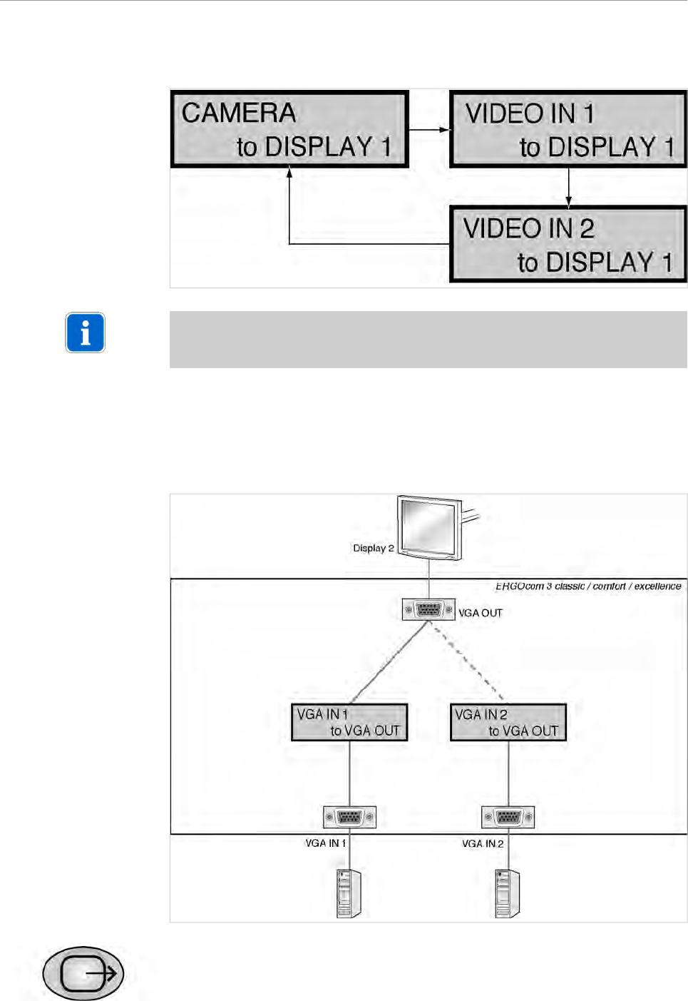
5.2.2 VGA OUT - set image source
▶ Hold down the VGA OUT button for < 2 seconds.
The last image source selected is shown in the status display. The status display
returns to operational mode after 5 seconds.
29/56
ERGOcom 3
5 Operation | 5.2 Operation, no display interface (classic)
See also: 5.2.1 Operational mode, Page 27
▶ Hold down the VGA OUT button for > 2 seconds.
The status display flashes and setting mode is activated.
▶ Use VGA OUT to select the required VGA input.
Note
If there is no input for 8 seconds, the ERGOcom 3 switches back to operational
mode.
This saves the last setting on the status display.
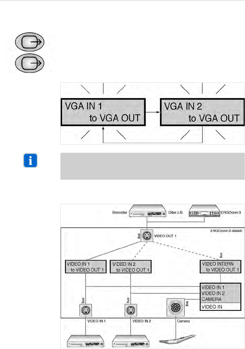
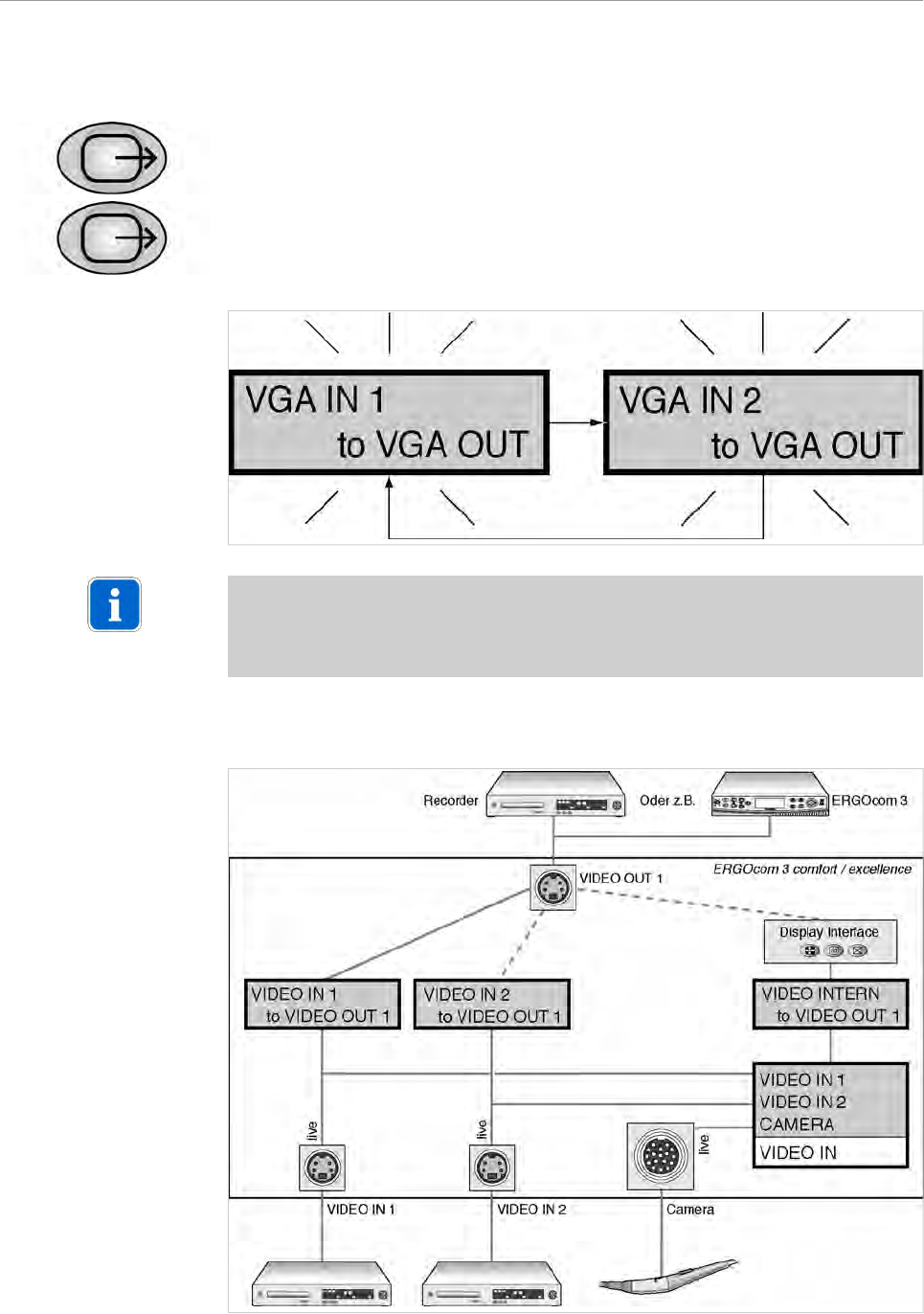
5.2.3 VIDEO OUT 1 - set image source
30/56
ERGOcom 3
5 Operation | 5.2 Operation, no display interface (classic)
▶ Hold down the VIDEO OUT 1 button for < 2 seconds.
The last image source selected is shown in the status display. The status display
returns to operational mode after 5 seconds.
See also: 5.2.1 Operational mode, Page 27
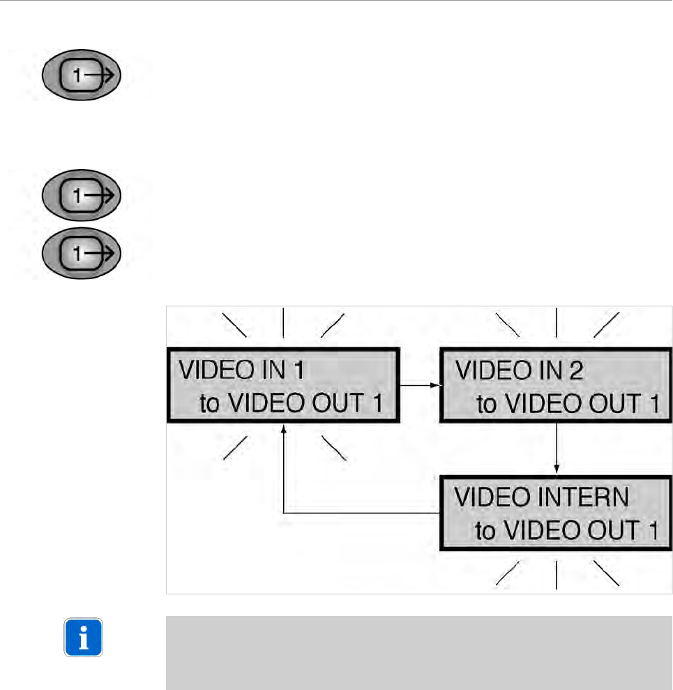
▶ Hold down VIDEO OUT 1 for > 2 seconds.
The status display flashes and setting mode is activated.
▶ Select the required VIDEO input by pressing the VIDEO OUT 1 button.
Note
If there is no input for 8 seconds, the ERGOcom 3 switches back to operational
mode.
This saves the last setting on the status display.
31/56
ERGOcom 3
5 Operation | 5.2 Operation, no display interface (classic)
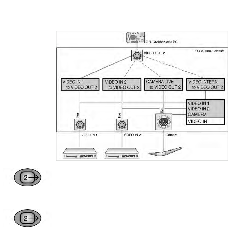
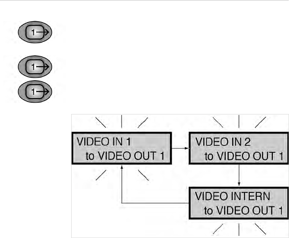
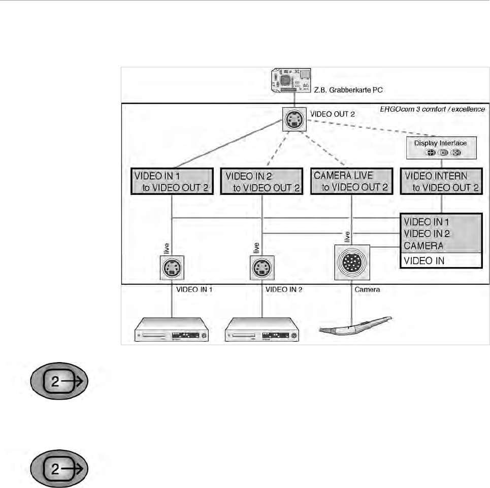
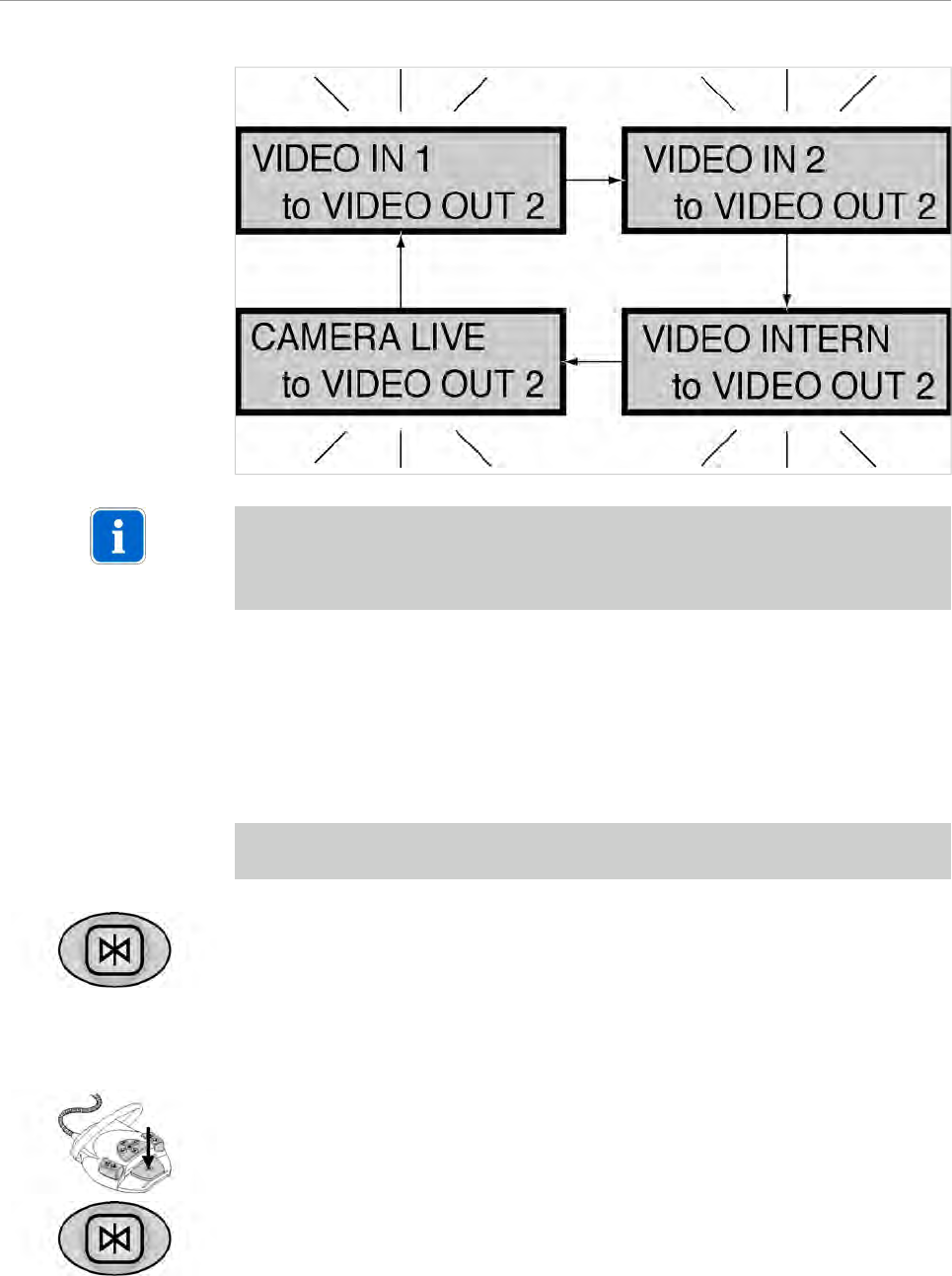
5.2.4 VIDEO OUT 2 - set image source
▶ Hold down the VIDEO OUT 2 button for < 2 seconds.
The last image source selected is shown in the status display. The status display
returns to operational mode after 5 seconds.
See also: 5.2.1 Operational mode, Page 27
▶ Hold down the VIDEO OUT 2 button for > 2 seconds.
The status display flashes and setting mode is activated.
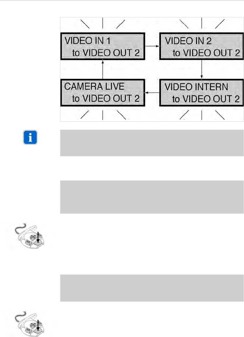
▶ Select the required VIDEO input by pressing the VIDEO OUT 2 button.
32/56
ERGOcom 3
5 Operation | 5.2 Operation, no display interface (classic)
Note
If there is no input for 8 seconds, the ERGOcom 3 switches back to operational
mode.
This saves the last setting on the status display.
5.2.5 Generate still
Prerequisite
● A video signal is shown on Display 1.
●TheERGOcom 3 is connected to a PC fitted with a grabber card by means of a
USB cable.
●On this PC, the KaVo Display Interface System software is installed.
▶ Hold down the footswitch for < 2 seconds.
The Generate still command is passed on to the PC.
5.2.6 Save still
Prerequisite
●TheERGOcom 3 is connected to a PC fitted with a grabber card by means of a
USB cable.
●On this PC, the KaVo Display Interface System software is installed.
▶ Hold down the footswitch for > 2 seconds.
The Generate still command is passed on to the PC.
33/56

ERGOcom 3
5 Operation | 5.2 Operation, no display interface (classic)
5.2.7 Audio signals
The audio signals will be linked synchronously to the relevant image signals.
34/56
ERGOcom 3
5 Operation | 5.3 Operation, with display interface (comfort/excellence)
5.3 Operation, with display interface (comfort/excellence)
Equivalent to ERGOcom 3 , comfort or excellence level.
In addition to excellence level, instructions for operation for the radio master
(ERGOremote) can be found in the separate UI.
See also: UIERGOremote
In all subsequent descriptions, please note the following: to view the selected option
on Display 1, the relevant source must be active.
5.3.1 Operational mode
In operational mode, it is possible to switch between VGA or VIDEO image sources,
including audio, shown on KaVo Display 1.
VGA IN - set image source
▶ Press the VGA IN button.
If a VIDEO image source was selected before, the last VGA IN image source
selected will be shown in the status display.
35/56
ERGOcom 3
5 Operation | 5.3 Operation, with display interface (comfort/excellence)
▶ Select the required VGA input by pressing the VGA IN button.
Note
If no image source is connected to VIDEO IN 1/2, the logo set in the OSD menu
display interface will be displayed.
See also:
5.4.5 Menu point, other, Page 49
VIDEO IN - set image source
▶ Press the VIDEO IN button.
If a VGA image source was selected before, the last VIDEO IN image source
selected will be shown in the status display.
36/56
ERGOcom 3
5 Operation | 5.3 Operation, with display interface (comfort/excellence)
▶ Select the required VIDEO input by pressing the VIDEO IN button.
Note
If no image source is connected to VIDEO IN 1/2, the logo set in the OSD menu
display interface will be displayed.
See also:
5.4.5 Menu point, other, Page 49
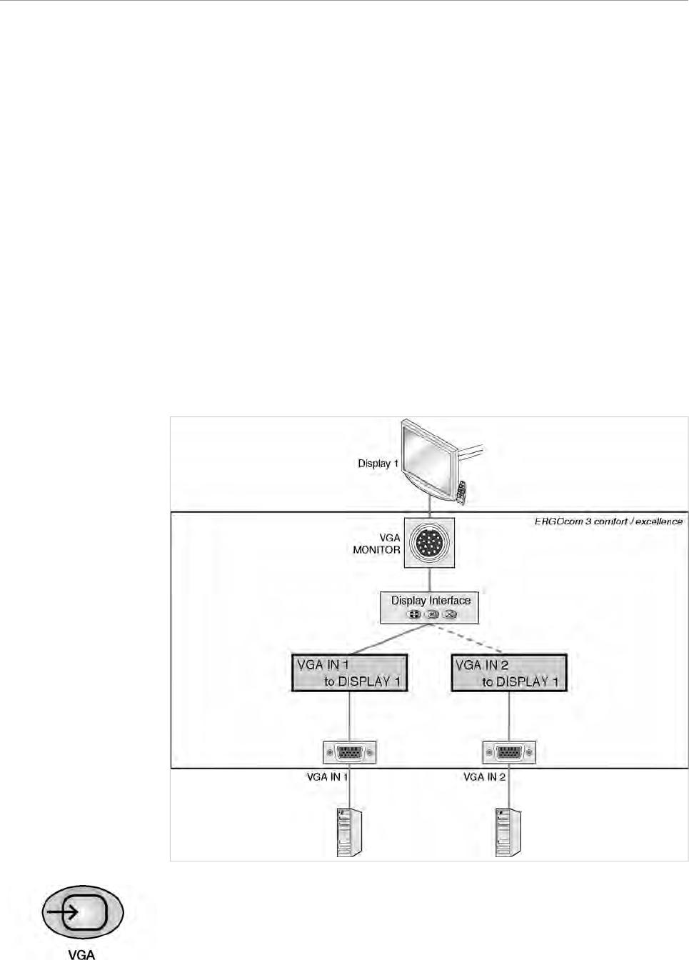
5.3.2 VGA OUT - set image source
▶ Hold down the VGA OUT button for < 2 seconds.
The last image source selected is shown in the status display. The status display
returns to operational mode after 5 seconds.
37/56
ERGOcom 3
5 Operation | 5.3 Operation, with display interface (comfort/excellence)
See also: 5.2.1 Operational mode, Page 27
▶ Hold down the VGA OUT button for > 2 seconds.
The status display flashes and setting mode is activated.
▶ Use VGA OUT to select the required VGA input.
Note
If there is no input for 8 seconds, the ERGOcom 3 switches back to operational
mode.
This saves the last setting on the status display.
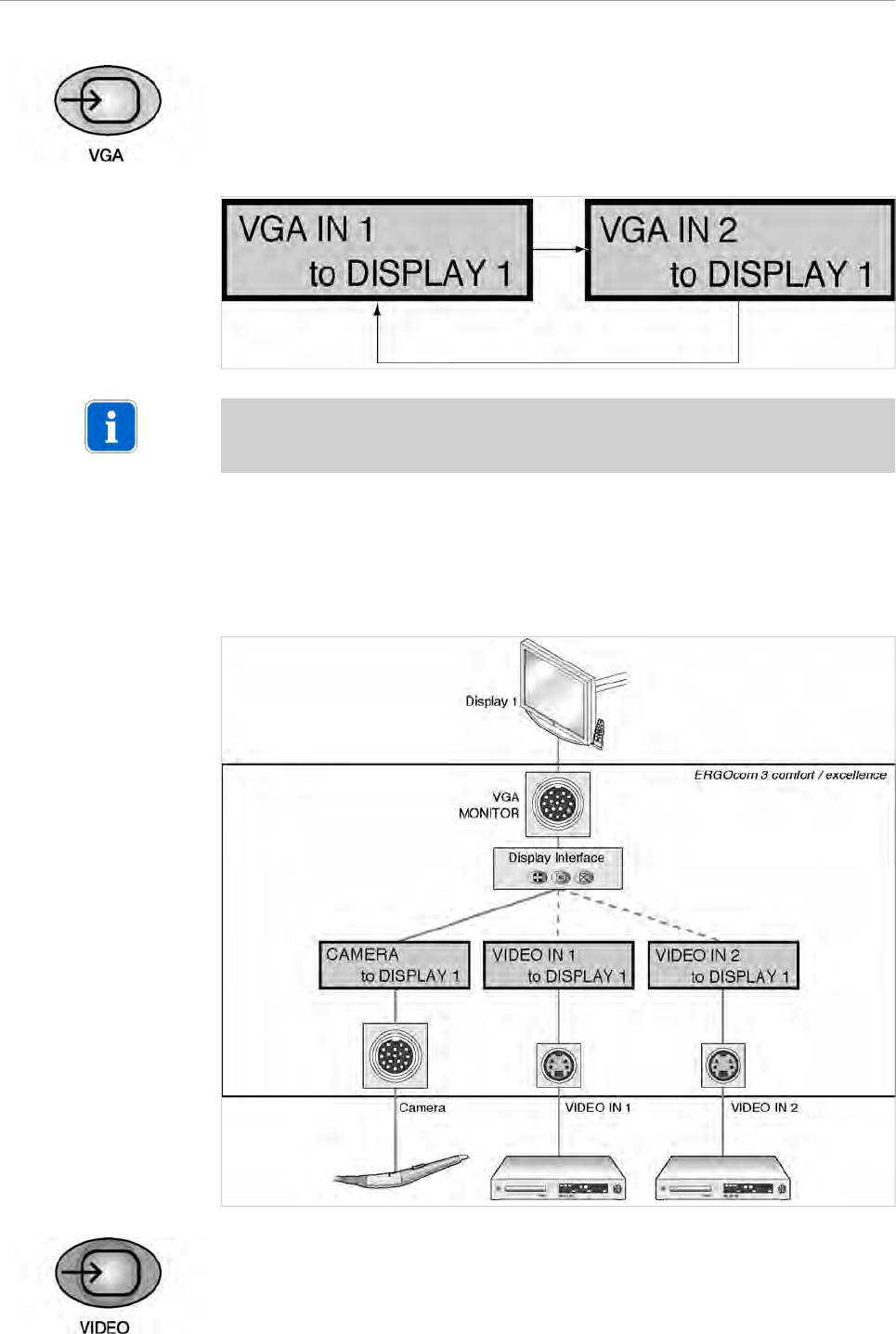
5.3.3 VIDEO OUT 1 - set image source
38/56
ERGOcom 3
5 Operation | 5.3 Operation, with display interface (comfort/excellence)
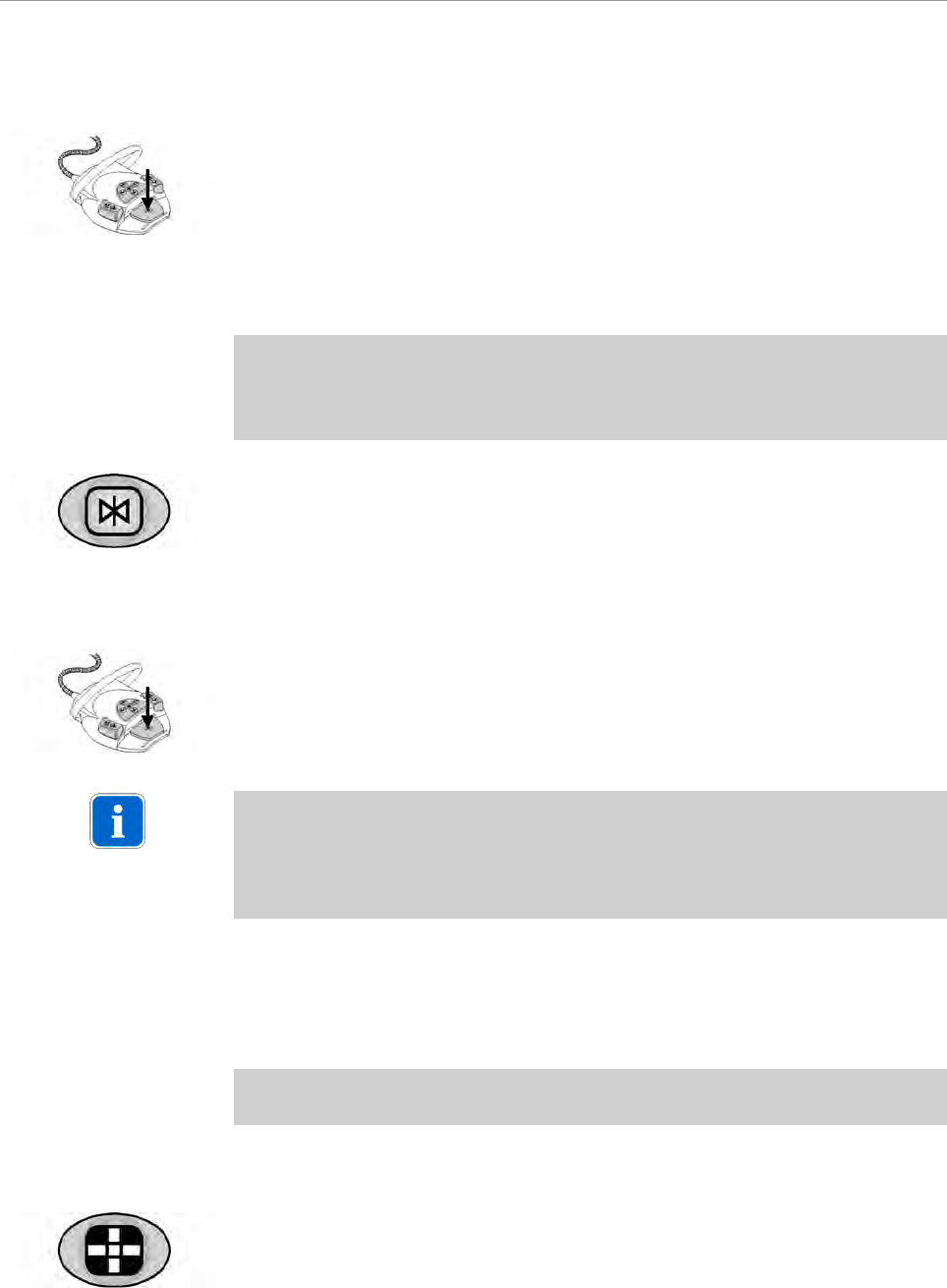
▶ Hold down the VIDEO OUT 1 button for < 2 seconds.
The last image source selected is shown in the status display. The status display
returns to operational mode after 5 seconds.
▶ Hold down VIDEO OUT 1 for > 2 seconds.
The status display flashes and setting mode is activated.
▶ Select the required VIDEO input by pressing the VIDEO OUT 1 button.
39/56
ERGOcom 3
5 Operation | 5.3 Operation, with display interface (comfort/excellence)
5.3.4 VIDEO OUT 2 - set image source
▶ Hold down the VIDEO OUT 2 button for < 2 seconds.
The last image source selected is shown in the status display. The status display
returns to operational mode after 5 seconds.
See also: 5.2.1 Operational mode, Page 27
▶ Hold down the VIDEO OUT 2 button for > 2 seconds.
The status display flashes and setting mode is activated.
▶ Select the required VIDEO input by pressing the VIDEO OUT 2 button.
40/56
ERGOcom 3
5 Operation | 5.3 Operation, with display interface (comfort/excellence)
Note
If there is no input for 8 seconds, the ERGOcom 3 switches back to operational
mode.
This saves the last setting on the status display.
5.3.5 Audio signals
The audio signals will be linked synchronously to the relevant image signals.
5.3.6 Generate still
Prerequisite
A video signal is shown on Display 1.
▶ Hold down the Freeze button for < 2 seconds.
A still is generated on Display 1 from the current video image.
or
▶ Hold down the footswitch for < 2 seconds.
A still is generated on Display 1 from the current video image.
▶ Press the Freeze button again to return to live image display and activate the
next image (1-4) as a live image.
41/56
ERGOcom 3
5 Operation | 5.3 Operation, with display interface (comfort/excellence)
or
▶ Press the footswitch again to return to live image display and activate the next
image (1-4) as a live image.
5.3.7 Save still
Prerequisite
●TheERGOcom 3 is connected to a PC fitted with a grabber card by means of a
USB cable.
●On this PC, the KaVo Display Interface System software is installed.
▶ Hold down the Freeze button for > 2 seconds.
The successful save is indicated on Display 1 with save.
or
▶ Hold down the footswitch for > 2 seconds.
The successful save is indicated on Display 1 with save.
Note
Saving the active image (image number is white) is possible in Full Screen and
Quad mode for the display.
The still is saved on the PC and on the internalERGOcom 3 USB drive as long as
on is selected for USBpict.store.
See also: 5.1.5 Menu points, Page 25
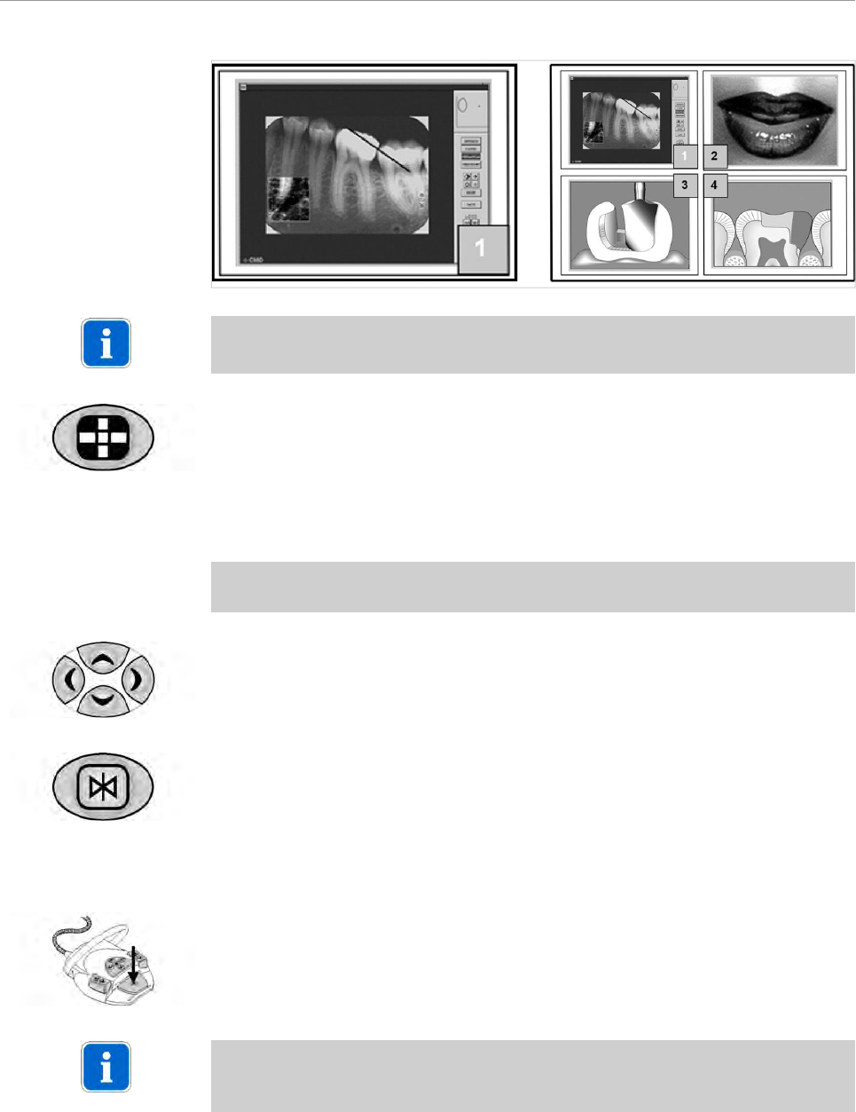
5.3.8 Change display view
Prerequisite
A video signal is shown on Display 1.
Images on Display 1 can be toggled between Full Screen mode and Quad mode.
▶ Press the Full Screen /Quad Mode button.
42/56
ERGOcom 3
5 Operation | 5.3 Operation, with display interface (comfort/excellence)
Note
The image number of the active image is shown in white.
▶ Press the Full Screen / Quad Mode button again to return to Full Screen mode.
5.3.9 Select image
Prerequisite
The image selected must be a still.
▶ Select the required image using the 4 navigation buttons.
The still selected is retained as a still.
▶ Press the Freeze button.
The still selected is deleted or turned into a live image.
or
▶ Press the footswitch.
The still selected is deleted or turned into a live image, and the next image number
is selected automatically.
Note
If this function is not required, the Freeze button has to be used for image selection
on theERGOcom 3 .
43/56
ERGOcom 3
5 Operation | 5.3 Operation, with display interface (comfort/excellence)
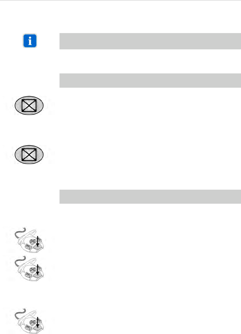
5.3.10 Delete image / images
Note
Possible in Full Screen and Quad mode.
ERGOcom 3
Prerequisite
The image selected must be a still.
▶ Hold down the Delete image / images button for < 2 seconds.
The still is deleted and the logo selected in the OSD menu display interface is
shown.
See also:
5.4.5 Menu point, other, Page 49
▶ Hold down the Delete image / images button for > 2 seconds.
All 4 stills are deleted and the logo selected in the OSD menu display interface
is shown.
Multi footswitch control
Prerequisite
4 stills are generated using the multi footswitch control.
See also: 5.3.6 Generate still, Page 41
▶ Press the footswitch again.
Display 1 shows the prompt "Delete all images?"
▶ Hold down the footswitch for > 2 seconds to delete all 4 stills.
The logo set in the OSD menu display interface is inserted.
or
▶ Hold down the footswitch for < 2 seconds to switch image 1 to a live image.
44/56
ERGOcom 3
5 Operation | 5.3 Operation, with display interface (comfort/excellence)
5.3.11 Change image source
Prerequisite
A still has to be generated.
See also: 5.3.6 Generate still, Page 41
▶ Put the camera in the holder.
▶ Press the footswitch.
TheERGOcom 3 switches to the image source selected before the camera was
removed.
45/56
ERGOcom 3
5 Operation | 5.4 Operation, OSD menu display interface
5.4 Operation, OSD menu display interface
The overview diagrams were structured according to the type of image source and
the connected function:
VGA main menu Overview of main menu with VGA IN 1 or VGA IN 2
image source.
VIDEO main menu Overview of main menu with CAMERA, VIDEO IN 1 or
VIDEO IN 2 image source.
Menu point, other This menu point is the same for all image sources.
5.4.1 Call OSD menu display interface
Prerequisite
The image source for which the display settings are to be changed must be selec-
ted.
See also:
5.2.1 Operational mode, Page 27
5.3.1 Operational mode, Page 35
▶ Press the OSD menu button.
The OSD menu display interface is inserted on Display 1.
▶ Press OSD menu again to leave the menu.
5.4.2 Operate OSD menu display interface
Prerequisite
The OSD menu display interface was called.
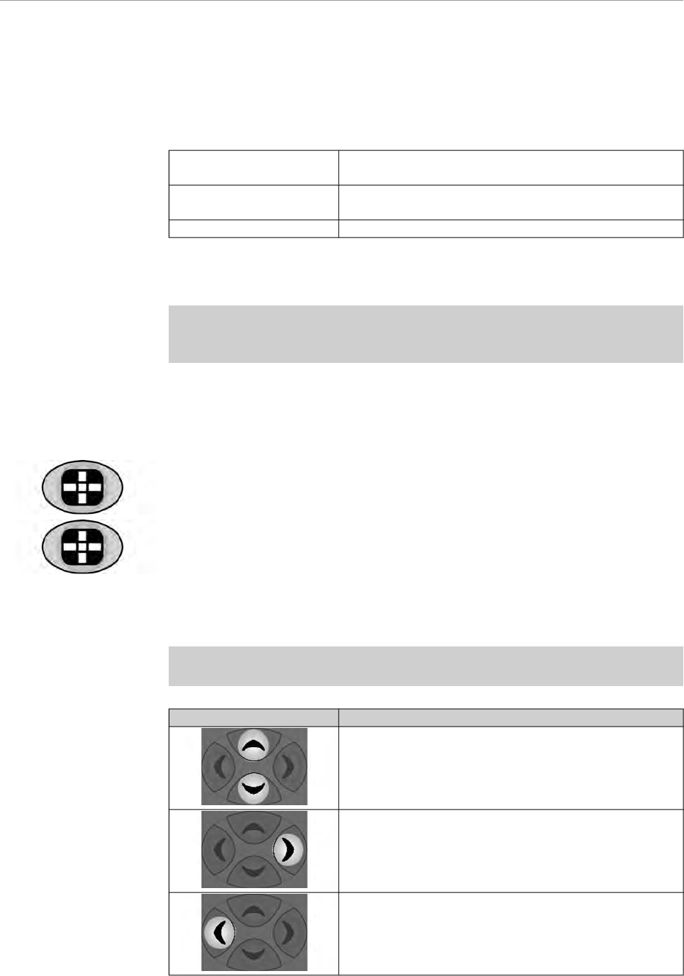
Navigation Function
Scroll in the current menu window. The menu point se-
lected will have a coloured background.
Select the menu point or setting to be changed.
The setting that can be changed is white.
Leave the selected menu point orsetting.
46/56
ERGOcom 3
5 Operation | 5.4 Operation, OSD menu display interface
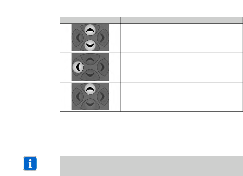
Navigation Function
Change settings.
Save changed setting.
Reset the selected menu point.
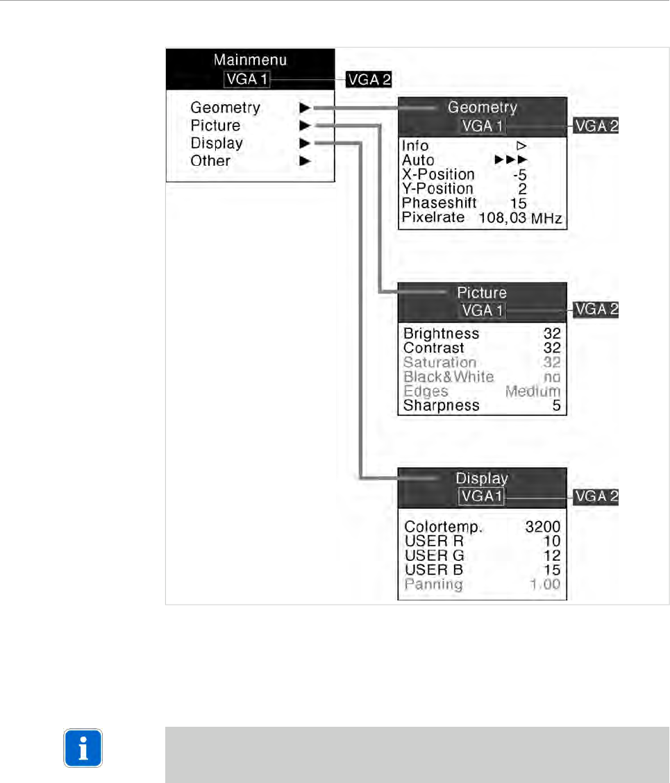
5.4.3 VGA main menu
There is a separate main menu for every VGA IN image source. This allows the
settings on Display 1 to be defined and saved for every image source.
Note
The requisite explanations of the individual menu points or settings are inserted
directly on Display 1.
47/56

ERGOcom 3
5 Operation | 5.4 Operation, OSD menu display interface
5.4.4 VIDEO main menu
There is a separate main menu for every VIDEO IN image source. This allows the
settings on Display 1 to be defined and saved for every image source.
Note
The requisite explanations of the individual menu points or settings are inserted
directly on Display 1.
48/56
ERGOcom 3
5 Operation | 5.4 Operation, OSD menu display interface
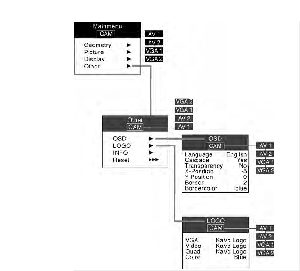
5.4.5 Menu point, other
This menu point is available in all main menus (VGA and VIDEO). However, it is not
saved separately for all menus, but only once, covering all menus.
Note
The requisite explanations of the individual menu points or settings are inserted
directly on Display 1.
49/56
ERGOcom 3
5 Operation | 5.4 Operation, OSD menu display interface
50/56
ERGOcom 3
6 Preparation methods DIN EN ISO 17664 | 6.1 Cleaning
6 Preparation methods DIN EN ISO 17664
6.1 Cleaning
6.1.1 Exterior cleaning by hand
The wide variety of drugs and chemicals used in dental practice means that damage
may occur to painted surfaces or plastics if anything is allowed to drip onto them.
Tests have shown that surfaces cannot be protected entirely against all substances
available on the market.
As damage to surfaces is very much dependent on the reaction times of these sub-
stances, it is essential for any spilled substances to be wiped away immediately
using a damp cloth.
Detergent recommended: KaVo Elastoclean.
The following detergents must not be used:
1. Strongly alkaline lyes
2. Acids
3. Detergents containing fluoride
4. Detergents containing ammonia
5. All kinds of scouring agent
▶Switch off Display 1 and ERGOcom 3 .
CAUTION
Damage caused by fluids.
Faults in electrical components.
▶ Protect device openings from the penetration of fluids.
▶ Use a soft cloth and mild cleaning fluid to clean the surface.
51/56
ERGOcom 3
6 Preparation methods DIN EN ISO 17664 | 6.2 Disinfection
6.2 Disinfection
CAUTION
Damage caused by fluids.
Faults in electrical components.
▶ Protect device openings from the penetration of fluids.
▶ Wipe surface with a soft, fluff-free cloth to disinfect them.
Note
Contaminated parts must be disinfected after every patient.
52/56

ERGOcom 3
6 Preparation methods DIN EN ISO 17664 | 6.3 Maintenance
6.3 Maintenance
The product does not require regular user maintenance.
53/56

ERGOcom 3
7 Safety checks
7 Safety checks
If an EC3 Display is integrated with an ERGOcom 3 , safety checks (SFC) must be
performed every 2 years. A detailed description of SFC can be found in the
engineer's instructions.
See also: EIERGOcom 3
54/56
ERGOcom 3
8 Troubleshooting
8 Troubleshooting
Fault Cause Remedy
No status display. ERGOcom 3 switched to standby. ▶ Leave Standby mode.
See also: 5.1.2 Standby, Page 24
ERGOcom 3 off. ▶ERGOcom 3 on.
Mains fuse burnt out. ▶ Test mains fuse and replace
where necessary.
ERGOcom 3 switches itself off and
cannot be switched back on imme-
diately.
Overheating. ▶ Ensure good ventilation for the
ERGOcom 3 .
See also: 4 Start-up, Page 20
Everything has stopped working. Mains failure / overvoltage. ▶ ERGOcom 3 to be switched off
and then switched on again after
5 seconds.
Access to USB hardware does not
work under Windows XP.
The Microsoft patch needed to ope-
rate the USB port is not installed on
the target computer.
▶ Install the required patch.
This can be done while installing
the CCCDIS.
See also: 4.1.3 Connect PC , Page
22
Selected image source (e.g. DVD
player) is not displayed.
The DVD player is switched off, or
no DVD has been inserted.
▶ Check image source.
No camera image is displayed. Treatment unit switched off. ▶ Switch on treatment unit.
Poor video quality. Poor image material. ▶ Only use image material that is of
good quality.
Poor PC image source quality. Display setting for graphics card not
the same as the display format set-
ting on the ERGOcom 3 .
▶ Adjust display format and gra-
phics card setting.
See also: 5.1.5 Menu points,
Page 25
Poor image quality. Incorrect settings in the OSD menu
display interface.
▶ Improve the image quality using
the options in the OSD menu.
See also: 5.4 Operation, OSD me-
nu display interface, Page 46
55/56
ERGOcom 3
9 Glossary
9 Glossary
Term Description
Display 1 Display 1 is the display connected via the VGA Monitor
interface and installed on the lamp mounting rod.
Display 2 Display 2 is the display connected via the VGA out in-
terface.
Full screen mode The image is displayed across the entire display area.
Quad mode Four independent images are shown in the display.
OSD menu display inter-
face
The OSD menu of the display interface. This is con-
trolled viaERGOcom 3 and shown in Display 1.
OSD menu, ERGOcom 3 The ERGOcom 3-specific OSD menu. This is shown in
the status display.
OSD menu, Display 1 The EC3 Display-specific OSD menu. This is controlled
and shown in the display.
56/56

1.003.1609 · Ma · 08.04-01 · EN

User instructions
ERGOremote
Always on the safe side.

Sales and Distribution:
KaVo Dental GmbH
Bismarckring 39
D-88400 Biberach
Tel.: ++ 49 / 73 51/ 56 - 0
Fax: ++ 49 / 73 51 / 56 – 14 88
Manufacturer:
Kaltenbach & Voigt GmbH
Bismarckring 39
D-88400 Biberach

User instructions ERGOremote
Table of contents
Table of contents
Table of contents ..............................................................................................................................................1
1 User Notes .....................................................................................................................................................3
1.1 User guidelines ........................................................................................................................................3
1.1.1 Abbreviations ..................................................................................................................................3
1.1.2 Symbols ..........................................................................................................................................3
1.2 Target audience .......................................................................................................................................4
1.3 Service .....................................................................................................................................................5
1.4 Provisions of guarantee ...........................................................................................................................6
1.5 Transport and storage ..............................................................................................................................7
1.5.1 The German packaging ordinance, 28 August 1998 ......................................................................7
1.5.2 Damage in transit ............................................................................................................................7
1.5.3 Storage ...........................................................................................................................................8
2 Safety .............................................................................................................................................................9
2.1 Description of safety instructions .............................................................................................................9
2.1.1 Hazard warning symbol ..................................................................................................................9
2.1.2 Structure .........................................................................................................................................9
2.1.3 Description of the different levels of hazard ....................................................................................9
2.2 Intended purpose ...................................................................................................................................10
2.2.1 General .........................................................................................................................................10
2.2.2 Product-specific ............................................................................................................................10
2.3 Safety instructions ..................................................................................................................................11
2.3.1 General .........................................................................................................................................11
3 Product description ......................................................................................................................................12
3.1 ERGOremote .........................................................................................................................................12
3.2 Rating plate ............................................................................................................................................13
3.3 Technical data ........................................................................................................................................14
4 Start-up ........................................................................................................................................................15
4.1 Insert battery ..........................................................................................................................................15
4.2 Learn channel ........................................................................................................................................16
5 Operation .....................................................................................................................................................17
5.1 Controls/displays ....................................................................................................................................17
5.1.1 Synchronise the ERGOremote to ERGOcom 3 ............................................................................17
5.1.2 Wake Up .......................................................................................................................................17
5.1.3 Sleep mode ...................................................................................................................................17
5.1.4 Send and receive status ...............................................................................................................17
5.1.5 Reset .............................................................................................................................................17
5.1.6 Delete image in Video mode .........................................................................................................18
5.1.7 Quad mode in Video mode ...........................................................................................................18
5.1.8 Freeze in Video mode ...................................................................................................................18
5.1.9 OSD Display Interface ..................................................................................................................19
5.1.10 Cursor keys .................................................................................................................................19
5.1.11 Video Input 2 to Display 1 ...........................................................................................................20
5.1.12 Video Input Camera to Display 1 ................................................................................................20
5.1.13 Video Input 1 to Display 1 ...........................................................................................................20
5.1.14 VGA Input 2 to Display 1 .............................................................................................................20
5.1.15 VGA Input 1 to Display 1 .............................................................................................................20
5.1.16 Standby .......................................................................................................................................20
5.1.17 Battery warning ...........................................................................................................................20
1/25

User instructions ERGOremote
Table of contents
6 Preparation methods DIN EN ISO 17664 ....................................................................................................22
6.1 Cleaning .................................................................................................................................................22
6.1.1 Exterior cleaning by hand .............................................................................................................22
6.2 Disinfection ............................................................................................................................................23
6.3 Maintenance ..........................................................................................................................................24
7 Glossary .......................................................................................................................................................25
2/25
User instructions ERGOremote
1 User Notes | 1.1 User guidelines
1 User Notes
1.1 User guidelines
Prerequisite
Please read these instructions before using the product to avoid operator error and
damage.
1.1.1 Abbreviations
Abbre‐
viation
Meaning
UI User instructions
SI Setup instructions
STI Service Technician's instructions
SFC Safety checks
IEC International Electrotechnical Commission
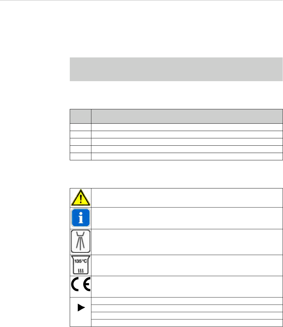
1.1.2 Symbols
See Safety/Hazard Warning Symbol chapter
Important information for users and Service Technicians
Thermally disinfectable
Sterilisable up to 135°C
CE (Communauté Européenne) marking. Products bearing this marking
conform to the requirements of the pertinent EC directives (applicable Eu‐
ropean standards).
Action prompt
Laser hazard warning sign
Laser sign
ESD - warning message
3/25

User instructions ERGOremote
1 User Notes | 1.2 Target audience
1.2 Target audience
This document is intended for use by dentists and other dental practice employees.
4/25

User instructions ERGOremote
1 User Notes | 1.3 Service
1.3 Service
Please send all questions about the product, services and maintenance to the fol‐
lowing addresses.
Always quote product serial number in any correspondence.
KaVo Dental GmbH
After Sales Service
Bahnhofstraße 20
D-88445 Warthausen
0049 - (0) 7351-56 2700
0049 - (0) 7351-18218
multimedia@kavo.de
www.kavo.com
KaVo Präsentations- und Servicezentrum Frankfurt (KaVo Presentation and Ser‐
vice Center, Frankfurt)
Hungener Straße 6-12
60389 Frankfurt
069 - 5 97 03 -94 / 95
KaVo Präsentations- und Servicezentrum Hamburg (KaVo Presentation and Ser‐
vice Center, Hamburg)
Sachsenstraße 5
20097 Hamburg
040 - 23 44 -77/ - 78
KaVo Präsentations- und Servicezentrum Düsseldorf (KaVo Presentation and Ser‐
vice Center, Düsseldorf)
Kaiserswerther Straße 35
40477 Düsseldorf
0211 - 49 91 -38 / -39
KaVo Präsentations- und Servicezentrum Berlin (KaVo Presentation and Service
Center, Berlin)
Uhlandstraße 20-25
10623 Berlin
030 - 7 91 94 84
KaVo Präsentations- und Servicezentrum Leipzig
Zweenfurther Straße 9
04827 Leipzig-Gerichshain
03 42 92 - 7 41 -12/ -13
5/25

User instructions ERGOremote
1 User Notes | 1.4 Provisions of guarantee
1.4 Provisions of guarantee
The KaVo end customer guarantee for the product named in the completion certi‐
ficate guarantees that the product functions correctly and that there are no faults in
the material or workmanship for a duration of 12 months following the purchase date,
according to the following conditions:
Following a reasonable complaint relating to defects or short delivery, KaVo gua‐
rantee to provide a replacement or perform repairs, whichever they deem most
suitable. Claims of any other nature, damages in particular, are excluded. In case
of default and gross negligence or intent, the latter only applies if there are no com‐
pelling legal provisions opposing it.
KaVo shall not be liable for defects and their consequences, which occur as a result
of normal wear and tear, or of improper cleaning or maintenance.
Non-observance of the operating, maintenance or connection regulations; calcina‐
tion or corrosion; impurities in the air and water supply; or chemical or electrical
effects, which are non-standard or not permitted according to company regulations.
As a general rule, this guarantee does not apply to lamps, glassware, rubber parts
or the colour durability of synthetic materials.
KaVo shall not be liable for defects or their consequences if they are likely to be a
direct result of actions or modifications by a customer or third party.
Any claims arising from this guarantee can only be lodged if the completion certifi‐
cate (carbon copy) has been sent in to KaVo and the operator/user is able to produce
the original.
6/25

User instructions ERGOremote
1 User Notes | 1.5 Transport and storage
1.5 Transport and storage
Note
When transporting used units that are already covered in dust, completely seal the
extraction vent at the rear of the unit (e.g. using suitable adhesive tape).
1.5.1 The German packaging ordinance, 28 August 1998
Note
Applies only to the Federal Republic of Germany.
KaVo transport packaging is disposed of and recycled by local waste management
and recycling companies under Germany's Dual System.
For more information about waste management and recycling, and for up-to-date
lists of local waste management and recycling companies, visit the following sites:
http://www.umweltdatenbank.de
http://www.quality.de
Any KaVo transport packaging that customers return to KaVo, at the customer's own
expense, shall be forwarded to the appropriate recycling companies at no extra cost
and with no reimbursement.
1.5.2 Damage in transit
Within Germany
If the outer packaging is noticeably damaged upon delivery, the following procedure
must be adhered to:
1. The recipient must record the loss or damage on the notice of receipt. The reci‐
pient and transport company employee delivering the product must both sign the
notice of receipt.
2. Leave the product and packaging in the condition they arrived in.
3. Do not use the product.
4. Report the damage to the transport company.
5. Report the damage to KaVo.
6. Under no circumstances should you return the damaged product to KaVo without
prior consultation.
7. Send the signed notice of receipt to KaVo.
If the product is damaged without there being any noticeable damage to the packa‐
ging upon delivery, you must proceed as follows:
1. Report the damage to the transport company as soon as possible within 7 days
of delivery.
2. Report the damage to KaVo.
3. Leave the product and packaging in the condition they arrived in.
4. Do not use the damaged product.
Note
If the recipient fails to adhere to any of the procedures mentioned above, the da‐
mage shall be considered as having arisen after delivery (pursuant to Germany's
General Terms and Conditions for Carriers (ADSp.), Article 28).
7/25
User instructions ERGOremote
1 User Notes | 1.5 Transport and storage
Outside Germany
Note
KaVo shall not be liable for damage caused in transit.
Check the shipment immediately upon delivery!
If the outer packaging is noticeably damaged upon delivery, the following procedure
must be adhered to:
1. The recipient must record the loss or damage on the notice of receipt. The reci‐
pient and transport company employee delivering the product must both sign the
notice of receipt.
The recipient may claim damages against the transport company only on the
basis of these recorded facts.
2. Leave the product and packaging in the condition they arrived in.
3. Do not use the product.
If the product is damaged without there being any noticeable damage to the packa‐
ging upon delivery, you must proceed as follows:
1. Report the damage to the transport company as soon as possible within 7 days
of delivery.
2. Leave the product and packaging in the condition they arrived in.
3. Do not use the damaged product.
Note
If the recipient fails to adhere to any of the procedures mentioned above, the da‐
mage shall be considered as having arisen after delivery (pursuant to the
Convention on the Contract for the International Carriage of Goods by Road (CMR)
Chapter V Article 30).
1.5.3 Storage
Note
Save packaging in case product requires sending away for servicing or repairs.
The symbols printed on the outer packaging apply to transportation and storage;
their meanings are as follows:
Keep upright in transit; this way up!
Handle with care
Keep dry
Stacking limitation.
Temperature limitations.
8/25
User instructions ERGOremote
2 Safety | 2.1 Description of safety instructions
2 Safety
2.1 Description of safety instructions
2.1.1 Hazard warning symbol
Hazard warning symbol
2.1.2 Structure
DANGER
The introduction describes the type and source of the danger.
This section shows what could happen if the instructions are not followed.
▶ The optional action shows what measures to take to avoid danger.
2.1.3 Description of the different levels of hazard
To avoid personal and material injury, safety instructions within this document are
classified into three levels of hazard.
CAUTION
CAUTION
Indicates a potentially dangerous situation which could result in material damage,
minor personal injury or non-severe personal injury.
WARNING
WARNING
Indicates a potentially dangerous situation which could result in fatal injury or se‐
vere personal injury.
DANGER
DANGER
This is the highest level of hazard. It indicates an imminently dangerous situation
which could result in fatal injury or severe personal injury.
9/25

User instructions ERGOremote
2 Safety | 2.2 Intended purpose
2.2 Intended purpose
2.2.1 General
The operator is required to make sure that the device is in a fully functional and safe
condition before commencing use.
The appropriate, comprehensive guidelines for this product and/or national laws,
national regulations and technlogical rules for starting up and operating have to be
applied and fulfilled in line with the specified, intended purpose of the KaVo product.
Note
Dispose of or recycle the waste materials produced without endangering human
health or the environment and under observance of the applicable national regu‐
lations that are in place.
Should you have any questions relating to the proper disposal of the KaVo product,
please contact your nearest KaVo office.
2.2.2 Product-specific
The ERGOremote remote control is for controlling ERGOcom 3 and/or for controlling
a computer by mouse.
It is a medical device accessory (protection class 1) for use within the patient envi‐
ronment of dental practices.
10/25
User instructions ERGOremote
2 Safety | 2.3 Safety instructions
2.3 Safety instructions
2.3.1 General
This KaVo product is not permitted for use in areas where there is a risk of explosion.
WARNING
Injuries or harm caused by damaged functional components.
Damaged functional components can cause personal harm or injury.
▶ If functional components are damaged: Stop work, remedy the problem or inform
the Service Technician.
CAUTION
Malfunction due to electromagnetic fields.
This product meets all the requirements that are in effect relating to electromagnetic
fields. Due to the complex interference between mobile phones and medical devi‐
ces, it is not, however, possible to completely exclude the possibility of the product
being affected by a functioning mobile phone.
▶ Refrain from using mobile phones in the practice and clinic area!
▶ Turn off electronic equipment, such as data memories, hearing aids etc, during
operation!
CAUTION
Risks caused by electromagnetic fields
Electromagnetic fields may interfere with the functions of implanted systems (such
as pacemakers).
▶ Consult the patient before treatment!
CAUTION
Damage caused by fluids.
Faults in electrical components.
▶ Protect product openings from the penetration of fluids.
The following individuals are authorised to repair and maintain the KaVo product:
▪ Service Technicians from KaVo offices.
▪ Service Technicians working for KaVo authorised dealers, specially trained by
KaVo.
11/25

User instructions ERGOremote
3 Product description | 3.1 ERGOremote
3 Product description
3.1 ERGOremote
1
Delete Image/Call ERGOcom 3 Con‐
trol
10
Standby/On
2
LED Radio Communication
11
VGA Input 1 to Display 1
3
Wake Up/Learn
12
Video Input 1 to Display 1
4
Freeze
13
Video Input Camera to Display 1
5
Mouse/Joystick
14
Left
6
Right
15
Up
7
Down
16
OSD
8
Video Input 2 to Display1
17
Quad mode
9
VGA Input 2 to Display 1
12/25
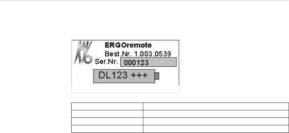
User instructions ERGOremote
3 Product description | 3.2 Rating plate
3.2 Rating plate
Type ERGOremote
Purchase order no. 1.003.0539
Serial no. nnnnnn
DL123+++ Battery and polarity labelling
13/25
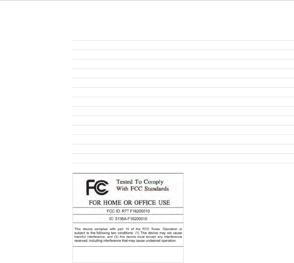
User instructions ERGOremote
3 Product description | 3.3 Technical data
3.3 Technical data
Wave band ISM 2.4 GHz
Number of channels 38
Maximum range without obstructions typically 100 m
Range in room < 20 m
Radiated power < 5 mW
Sleep mode < 10 µA
Standby typically 3 mA
Send operation typically 100 mA
Receive operation typically 80 mA
EN 300,440-1-2 Use of product spectrum
EN 301,489-1 EMC
EN 60950 Safety and low voltage directive
Authorisation according to R&TTE, FCC
14/25
User instructions ERGOremote
4 Start-up | 4.1 Insert battery
4 Start-up
4.1 Insert battery
Note
A DL 123 battery is supplied with the equipment.
Only use original batteries. We cannot provide a functional guarantee for other
batteries.
▶ Remove screw to open battery compartment.
▶ Insert the battery correctly in the compartment (in line with pole labels).
15/25
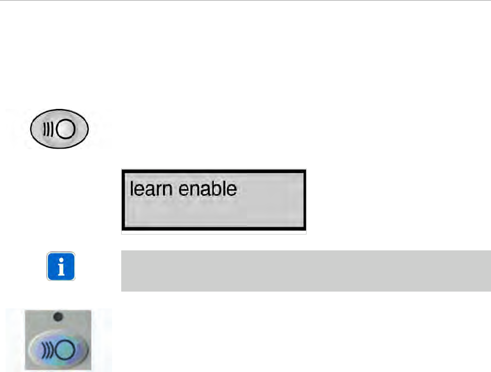
User instructions ERGOremote
4 Start-up | 4.2 Learn channel
4.2 Learn channel
The ERGOremote 's radio code is synchronised with the channel configured
onERGOcom 3 .
▶ Hold down the Channel Selection button on ERGOcom 3 for more than 2 se‐
conds.
Learn Channel Mode appears on the status display.
Note
If the channels do not synchronise within approx. 30 seconds, ERGOcom 3 swit‐
ches back to operational mode.
▶ Hold down the Wake Up/Learn button on the ERGOremote for more than 3 se‐
conds.
The green LED will be lit for 3 seconds to show that synchronisation is complete.
The green LED will flash to indicate that radio communication has not been set up.
16/25

User instructions ERGOremote
5 Operation | 5.1 Controls/displays
5 Operation
5.1 Controls/displays
5.1.1 Synchronise the ERGOremote to ERGOcom 3
Note
Channel 1 is set as a default. If there are a number of different ERGOremote
and ERGOcom 3 instruments in use at the practice, a different channel must be
set and the associated learning procedure completed in every room of the practice.
▶ Switch on Learn mode on ERGOcom 3 .
See also:
4.2 Learn channel, Page 16
5.1.2 Wake Up
▶ Before using the ERGOremote, press the Wake Up button or any other function
button (apart from the joystick.)
The LED is lit up for approx. 3 seconds.
An internal calibration is run during this period. The joystick must not be moved
about. All the other functions are available immediately.
5.1.3 Sleep mode
Once the buttons or joystick have been operated, ERGOremote remains in an ope‐
rative state for approx. 30 seconds. Once this 30 seconds is up, ERGOremote
automatically returns to sleep mode.
5.1.4 Send and receive status
The green LED acknowledges every active send and receive operation.
5.1.5 Reset
If the green LED is constantly flashing, this indicates a disruption in the radio link.
To remedy the disruption, reset the instrument.
17/25
User instructions ERGOremote
5 Operation | 5.1 Controls/displays
▶ Press the Standby button.
The right, left, up and down button functions are reset.
Note
ERGOcom 3 and the ERGOcom 3 display switch to Standby mode.
5.1.6 Delete image in Video mode
You can use the cursor buttons to navigate from one image to another. A brighter
image number indicates which image is active.
▶ Press delete.
The active image in Quad or Full Screen mode is deleted.
5.1.7 Quad mode in Video mode
You use this button to toggle between Full Screen and Quad mode.
5.1.8 Freeze in Video mode
Generate still
▶ Press the Freeze button.
The activated image is frozen.
Return to live image
▶ Hold down Freeze button for less than 3 seconds.
The still switches back to a live image.
Save still
▶ Hold down Freeze button for more than 3 seconds.
The still is saved in the USB memory of ERGOcom 3 or on the PC, depending
on the minimum system requirements.
18/25

User instructions ERGOremote
5 Operation | 5.1 Controls/displays
5.1.9 OSD Display Interface
▶ Press the OSD button.
The On Screen Display appears.
See also: ERGOcom 3 Instructions for Use
5.1.10 Cursor keys
Joystick
Prerequisite
The corresponding PC is connected via the USB interface of ERGOcom 3 .
The joystick can be used to move the cursor on the PC interface.
If the z axis in ERGOcom 3 is activated, you can perform click and double-click
functions by placing axial pressure on the joystick.
Up
In VGA mode, the up button is used to scroll through active menus.
In Video mode and OSD (Display Interface) mode, it can be used to navigate bet‐
ween the four images.
Right
In VGA mode, the right button is used to control the cursor - equivalent to the right-
hand mouse button.
In Video mode and OSD (Display Interface) mode, it can be used to navigate bet‐
ween the four images.
Left
In VGA mode, the left button is used to control the cursor - equivalent to the left-
hand mouse button.
In Video mode and OSD (Display Interface) mode, it can be used to navigate bet‐
ween the four images.
19/25
User instructions ERGOremote
5 Operation | 5.1 Controls/displays
Down
In VGA mode, the down button is used to scroll through inactive menus.
In Video mode and OSD (Display Interface) mode, it can be used to navigate bet‐
ween the four images.
5.1.11 Video Input 2 to Display 1
This button is used to switch the incoming image signal at Video Input 2 Directly to
Display 1.
5.1.12 Video Input Camera to Display 1
This button is used to switch the incoming image signal at the Video Input Camera
directly to Display 1.
5.1.13 Video Input 1 to Display 1
This button is used to switch the incoming image signal at Video 1 directly to Display
1.
5.1.14 VGA Input 2 to Display 1
This button is used to switch the associated image contents at VGA Input 2 directly
to Display 1.
5.1.15 VGA Input 1 to Display 1
This button is used to switch the associated image contents at VGA Input 1 directly
to Display 1.
5.1.16 Standby
Select this button to switch ERGOcom 3 and Display 1 over to power saving mode.
This saves power and prolongs the life cycles of the instruments.
5.1.17 Battery warning
Once the ERGOremote has undergone a certain length of operation, it will become
necessary to change its energy source. This is monitored by the instrument.
20/25

User instructions ERGOremote
5 Operation | 5.1 Controls/displays
If the cell voltage falls below the level required for safe operation, the red LED will
flash for approximately 3 seconds after wake-up indicating that the battery needs
replacing.
21/25

User instructions ERGOremote
6 Preparation methods DIN EN ISO 17664 | 6.1 Cleaning
6 Preparation methods DIN EN ISO 17664
6.1 Cleaning
6.1.1 Exterior cleaning by hand
The wide variety of drugs and chemicals used in dental practice means that damage
may occur to painted surfaces or plastics if anything is allowed to drip onto them.
Tests have shown that surfaces cannot be protected entirely against all substances
available on the market.
As damage to surfaces is very much dependent on the reaction times of these sub‐
stances, it is essential for any spilled substances to be wiped away immediately
using a damp cloth.
Detergent recommended: KaVo Elastoclean.
The following detergents must not be used:
1. Strongly alkaline lyes
2. Acids
3. Detergents containing fluoride
4. Detergents containing ammonia
5. All kinds of scouring agent
CAUTION
Damage caused by fluids.
Faults in electrical components.
▶ Protect product openings from the penetration of fluids.
▶ Use a soft cloth and mild cleaning fluid to clean the surface.
22/25

User instructions ERGOremote
6 Preparation methods DIN EN ISO 17664 | 6.2 Disinfection
6.2 Disinfection
CAUTION
Damage caused by fluids.
Faults in electrical components.
▶ Protect product openings from the penetration of fluids.
▶ Wipe surface with a soft, fluff-free cloth to disinfect them.
23/25

User instructions ERGOremote
6 Preparation methods DIN EN ISO 17664 | 6.3 Maintenance
6.3 Maintenance
The product does not require regular user maintenance.
24/25
User instructions ERGOremote
7 Glossary
7 Glossary
Term Description
Display 1 Display 1 is the display connected via the VGA Monitor
interface and installed on the lamp mounting rod.
Display 2 Display 2 is the display connected via the VGA out in‐
terface.
Full screen mode The image is displayed across the entire display area.
Quad mode Four independent images are shown in the display.
OSD menu display inter‐
face
The OSD menu of the display interface. This is con‐
trolled via ERGOcom 3 and shown on Display 1.
OSD menu, ERGOcom 3 The ERGOcom 3-specific OSD menu. This is shown in
the status display.
OSD menu, Display 1 The ERGOcom 3 display-specific OSD menu. This is
controlled and shown in the display.
25/25

1.003.1631 · hw · 31.01.2005 - 02 · en