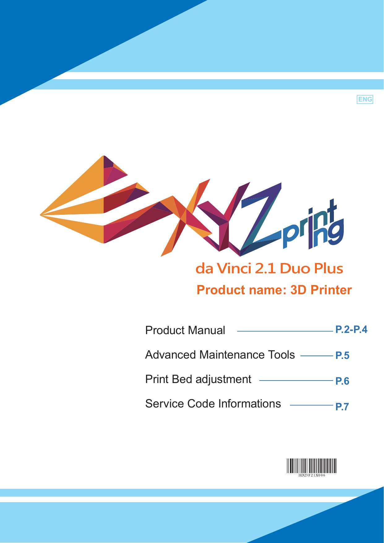
XYZprinting 3F21X 3D Printer User Manual HD23F21X006 QUICK GUIDE EN R1 indd
XYZprinting, Inc. 3D Printer HD23F21X006 QUICK GUIDE EN R1 indd
UserManual.wiki
>
XYZprinting
>
3F21X User Manual
User Manual
Navigation menu
Upload a User Manual
Namespaces
Wiki Guide
HTML
PDF
Info
Views
User Manual
Discussion / Help
Navigation
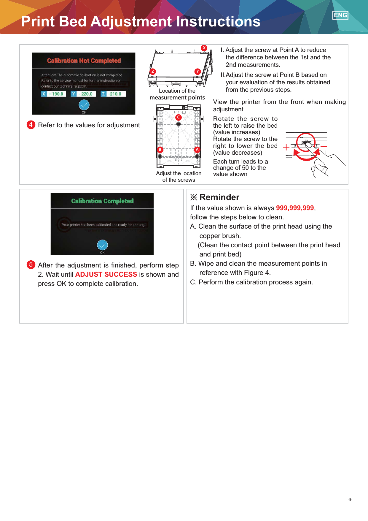
![-10-ENG)RUIXUWKHULQIRUPDWLRQDQGLQVWUXFWLRQRIWKHVHUYLFHFRGHSOHDVHUHIHUWR;<=SULQWLQJZHEVLWHKWWSVXSSRUW[\]SULQWLQJFRPRUFRQWDFWVHUYLFHFHQWHUIRUKHOSPrint Bed Adjustment InstructionsService Code Display Panel Description炵炵炵 Print bed heating error; critical temperature detected炵炵炵炵 Extruder(s) heating error; critical temperature detected炵炵炵 X axis motor failed results moving failed or X axis home sensor failed results home detect failed炵炵炵 Y axis motor failed results moving failed or Y axis home sensor failed results home detect failed炵炵炵 Z axis motor failed results moving failed or Z axis home sensor failed results home detect failed炵炵炵 Memory storage cannot read/write炵炵炵 Flashrom cannot read/write炵炵炵 Extruder or heated bed higher/lower than maximum/minimum temperature during printing 炵炵炵 Extruder cannot heat to the specified temperature](https://usermanual.wiki/XYZprinting/3F21X/User-Guide-2273866-Page-10.png)
![-10-ENG)RUIXUWKHULQIRUPDWLRQDQGLQVWUXFWLRQRIWKHVHUYLFHFRGHSOHDVHUHIHUWR;<=SULQWLQJZHEVLWHKWWSVXSSRUW[\]SULQWLQJFRPRUFRQWDFWVHUYLFHFHQWHUIRUKHOSPrint Bed Adjustment InstructionsService Code Display Panel Description炵炵炵 Print bed heating error; critical temperature detected炵炵炵炵 Extruder(s) heating error; critical temperature detected炵炵炵 X axis motor failed results moving failed or X axis home sensor failed results home detect failed炵炵炵 Y axis motor failed results moving failed or Y axis home sensor failed results home detect failed炵炵炵 Z axis motor failed results moving failed or Z axis home sensor failed results home detect failed炵炵炵 Memory storage cannot read/write炵炵炵 Flashrom cannot read/write炵炵炵 Extruder or heated bed higher/lower than maximum/minimum temperature during printing 炵炵炵 Extruder cannot heat to the specified temperatureFCC Statement This equipment has been tested and found to comply with the limits for a Class B digital device, pursuant to part 15 of the FCC Rules. These limits are designed to provide reasonable protection against harmful interference in a residential installation. This equipment generates, uses and can radiate radio frequency energy and, if not installed and used in accordance with the instructions, may cause harmful interference to radio communications. However, there is no guarantee that interference will not occur in a particular installation. If this equipment does cause harmful interference to radio or television reception, which can be determined by turning the equipment off and on, the user is encouraged to try to correct the interference by one or more of the following measures: —Reorient or relocate the receiving antenna. —Increase the separation between the equipment and receiver. —Connect the equipment into an outlet on a circuit different from that to which the receiver is connected. —Consult the dealer or an experienced radio/TV technician for help. FCC Radiation Exposure Statement This device complies with FCC radiation exposure limits set forth for an uncontrolled environment and it also complies with Part 15 of the FCC RF Rules. This equipment must be installed and operated in accordance with provided instructions and the antenna(s) used for this transmitter must be installed to provide a separation distance of at least 20 cm from all persons and must not be co-located or operating in conjunction with any other antenna or transmitter. End-users and installers must be provide with antenna installation instructions and consider removing the no-collocation statement. This device complies with Part 15 of the FCC Rules. Operation is subject to the following two conditions: (1) this device may not cause harmful interference, and (2) this device must accept any interference received, including interference that may cause undesired operation. Caution! Any changes or modifications not expressly approved by the party responsible for compliance could void the user's authority to operate the equipment.](https://usermanual.wiki/XYZprinting/3F21X/User-Guide-2273866-Page-11.png)