XYZprinting 3F21X 3D Printer User Manual HD23F21X006 QUICK GUIDE EN R1 indd
XYZprinting, Inc. 3D Printer HD23F21X006 QUICK GUIDE EN R1 indd
User Manual

-1-
ENG
Product Manual
Advanced Maintenance Tools
Print Bed adjustment
Service Code Informations
P. 2- P. 4
P. 5
P.6
P.7
ENG
Product name: 3D Printer
-2-
ENG
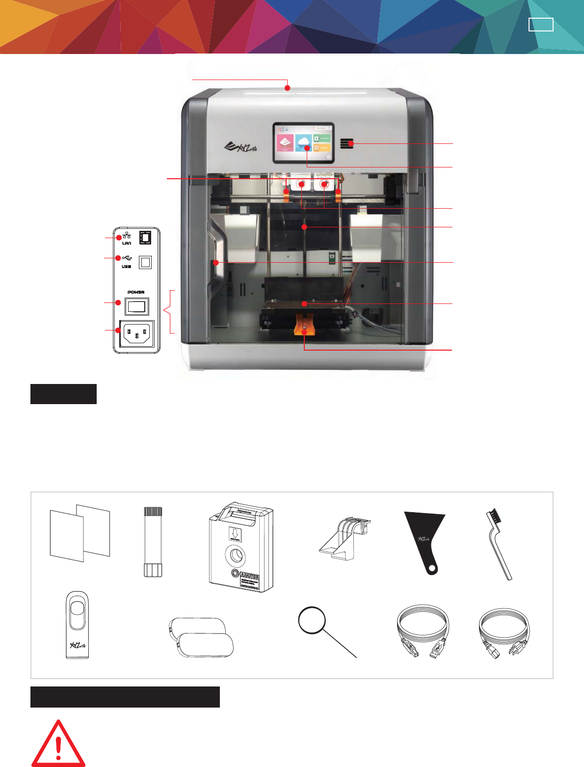
Filament Slot
USB Port
LAN Port
Speaker
Display Panel
Extruder Module
Z-Axis
Front Door
Print Bed
Remove the print
bed fi xing screws
and printing
module fi xers
Power Switch
Power
Connector
Remove the
packaging supports
Product Manual
Overview
Important safety Instruction
This guide provides details on how to start off your da Vinci 2.1 Duo Plus 3D printer correctly.
Please read the instructions before starting to print.
•How to open the box safely
•How to load fi lament
•Getting to know XYZWare software
•Do not place the printer in humid or dusty environment such as bathrooms and high traffic
areas.
•Do not place the printer on a rickety surface and/or inclined position. Printer may fall down/or
tumble and it may cause serious injury.
•Do not touch the interior of the printer while printing. As it may be hot and include moving parts.
Please keep the front door closed during printing to avoid injury.
GLUE STICK
ƑUser Quick Guide
ƑUSB Flash Driver ƑDecorative Plate x2 Ƒ Cleaning Wire x 5 ƑPower Cord
ƑGlue Stick
ƑFilament Cartridge x2
ƑCartridge Locker x2
ƑUSB Cable
Ƒ Scraper Ƒ Copper Brush
-3-
ENG
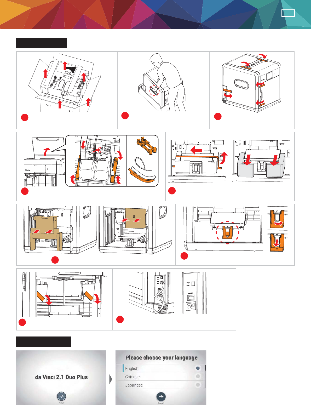
Open the box
Initial Settings
123
45
67
89
Open the box and remove the
accessories and the cushion.
Take out the printer by holding
the grip holds.
Remove plastic bag and
tapes.
Open the top door, then remove packaging supports
and tapes.
Remove the print bed fi xing tapes and cushion.
Remove the tapes and cardboard. Remove the screw and plastic piece
under print bed.
Remove the drip tray fi xing tapes. Connect the printer to your PC first using
USB cable then turn on the power switch.
•After powering on the printer for the fi rst time, complete the simple setup as instructed on the screen.
Then select language and press "Next" to proceed.
Packing
supports x2
Cable tie
x1
Tapes x2
A
B
A
B
Product Manual
GLUESTICK
PRINTING
-4-
ENG
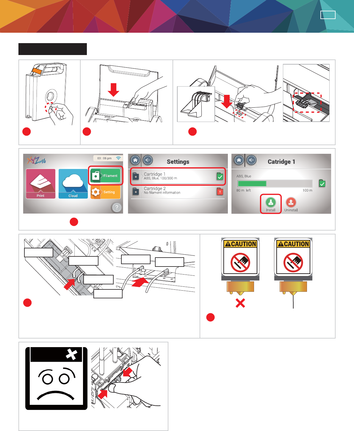
Install Cartridge
12 3
4
5
6
Remove the
fi lament stopper.
Install new fi lament cartridge
into the empty slot.
Place and push to fi x the cartridge locker
to the slot.
Select "Filament" > "Cartridge 1" > "Load".
Insert fi lament into the guide hole until the printer starts to
load fi lament. (When the loading begins, you will hear the
sound of motor and can see the fi lament is pulled into the
printer.)
When fi lament is dripping off the nozzle,
tape "OK" to fi nish.
If fi lament loading failed, grasping the release
arms may help to fi x the issue.
Note:
Do Not Touch. Do Not Touch.
Product Manual
Guide Hole 1
Guide Hole 2
Cartridge 2
Cartridge 1
Guide Hole 1 Guide Hole 2
-5-
ENG
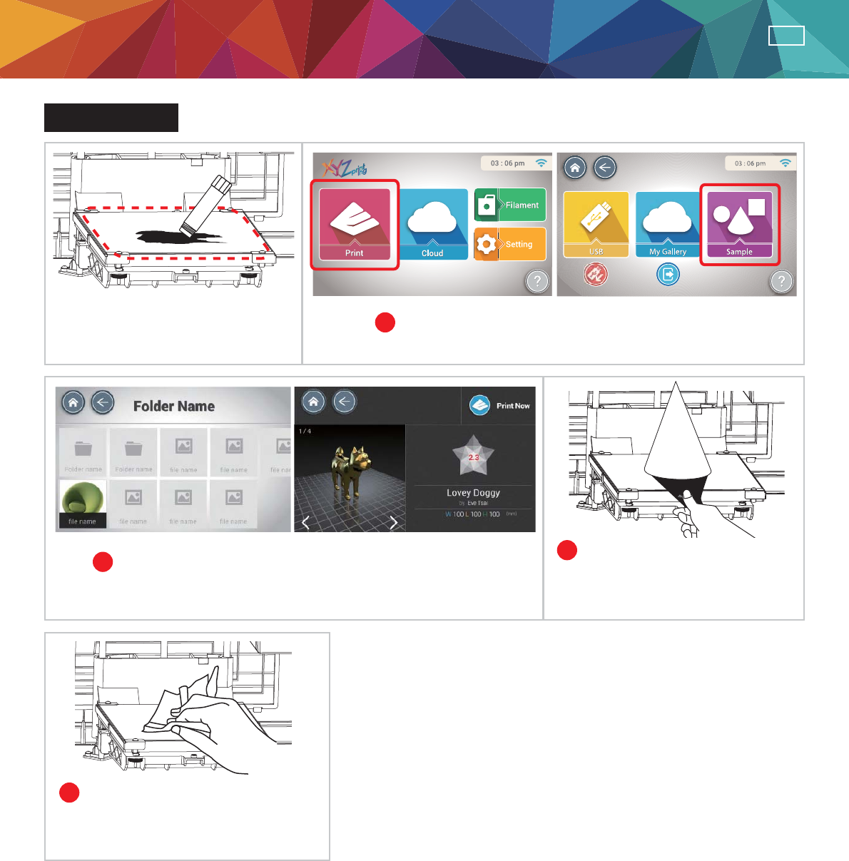
Sample Print
Apply glue to print bed before
printing. Glued area depends on the
flat measurement or object to be
printed.
1
2
4
3
Select "Print" > "Sample" on the screen.
Select a sample to print, and tap "Print".
Finally use a damp cloth to clean
the print bed.
After the printing is completed
and the print bed became cool,
use a scraper to take out the
object.
PRINTING
Product Manual
-6-
ENG
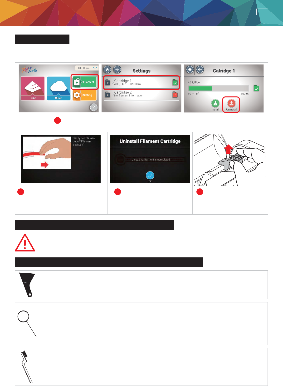
234Filament is unloaded from extruder
automatically. Pull fi lament out from
the guide hole when prompted.
When fi lament is pulled out,
press "OK".
Remove cartridge locker
and the catridge.
important safety Instruction
Information and usage of the advanced maintenance tools
The maintenance tools provided should be only handlde by an adult. Please keep tools
away from children. Incorrect handling or maintenance of the printer may cause damage
to the product or personal injury.
ÝScraper
Scraper is used to remove printed object from print bed when printing fi nished.
(Caution: Do not remove the printed object while the print bed is hot.)
ï Copper Brush
Cooper brush is used to clean and remove moiten filament left on the tip or surface of the
extruder(s) and inside the drive gear. When the printer falls to "Calibrate" consistently, please
use the cooper brush to clean and remove the fi lament pieces from the extruder(s).
ï Cleaning Wire
Cleaning wire is used to remove the fi lament left in the path inside the clogged nozzle when the
moiten fi lament has affect printing quality.
(Caution: Print bed may be hot during cleaning, please keep away from the platform to avoid personal injury.)
When cleaning the print nozzle, gear or fi lament path please ensure to keep hands clear of the
print bed which may be hot.
PRINTING
Unload fi lament
1Select "Filament" > "Cartridge1" (or "Cartridge 2") > "Uninstall" on the screen.
Note: Please always complete the procedure for "FILAMENT UNLOADING" before changing a new cartridge.
Never cut off the fi lament from the extruder to prevent extruders from clogged.
Product Manual & Maintenance Tools
-7-
ENG
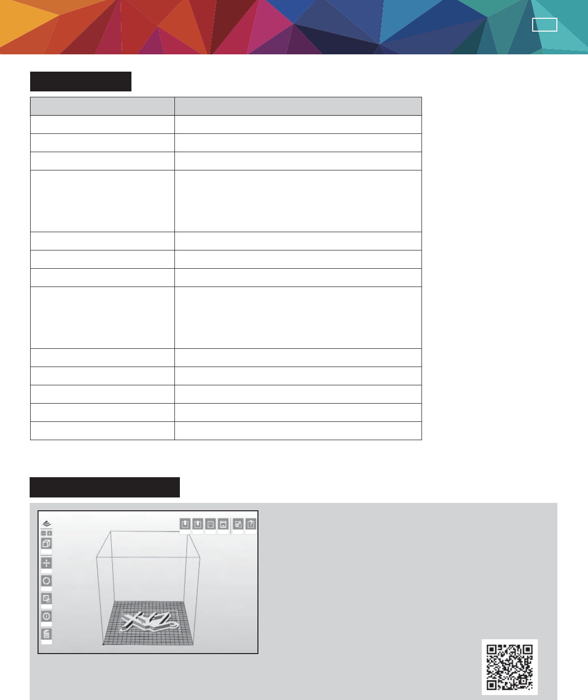
Specifi cations
Know about XYZware
Print Technology Fused Filament Fabrication(FFF)
Dual Head
15 x 20 x 20 cm
1.75 mm
0.4 mm
Touch Panel
Buzzer
Speaker
LED
28.5 Kg
100-240V, 50~60Hz
Standard 200 microns
Speed 300 microns
Ultra fast 400 microns
Custom 100-400 microns
USB 2.0 x1
WiFi
LAN
USB Flash Driver
Print Head
Layer Resolution Setting
Filament Diameter
Nozzle Diameter
Display
Indicator
Indicator
Lighting
Weight
Connectivity
AC Input
Build Volume (W x D x H)
Feature da Vinci 2.1 Duo Plus 3D Printer
Import
View
Move
Rotate
Scale
Info
Remove
Export Save Print Settings Help
For Mac OS and Win8 / 8.1 user or software related topics,
please visit following webpage for further information and
download the proper XYZware version:
http://support.xyzprinting.com/downloads
˥XYZware˦is developed by XYZPrinting Inc. It is
designed for everyone with or without modeling skill. You
can view the model in various perspectives by importing
(*.stl) fi le to it. It is also used to print objects from da Vinic
3D printer. XYZWare can be found in the bundle installation
disc. To check our latest software updates and further
information. Please go to:
http://support.xyzprinting.com/manuals
澿Notice:
Some instruction and video tutorials might require online registration to obtain authorization.
Maintenance Tools
-8-
ENG
Print Bed Adjustment Instructions
This print bed has been calibrated by our professional technician before
shipment. Do not adjust the platform yourself unless necessary, or contact our
Technical Consulting
:
0809-016-225
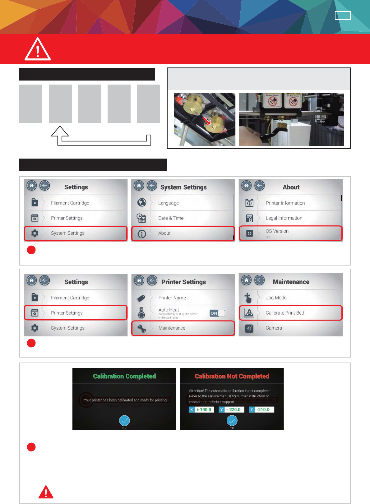
Print bed adjustment fl ow chart
Instructions on print bed adjustment
Step Step Step Step Step
12345
3HUIRUPDJDLQ
To clean the molted fi lament from nozzle thoroughly, it is
recommended to activate “UNLOAD FILAMENT” function
to keep heating the extruder for better cleaning.
&KHFNLISULQWHUILUPZDUHLVXSGDWHGWRWKHODWHVWYHUVLRQ
7DS6HWWLQJV!6\VWHP6HWWLQJV!$ERXW!)LUPZDUH9HUVLRQ!2.
Perform calibration:
Select "Settings" > "Printer Settings" > "Maintenance" > "Calibrate Print Bed" > "OK".
Note: During the measurement process, the print bed and print module will be heated.
Care should be taken during operation!
I. If ADJUST SUCCESS is shown.
The printer does not need adjustment and press OK to exit.
II. If ADJUST FAIL is shown.
The printer needs adjustment, refer to the values shown.
&DOLEUDWLRQ&RPSOHWHG&DOLEUDWLRQ1RW&RPSOHWHG
1
2
3
-9-
ENG
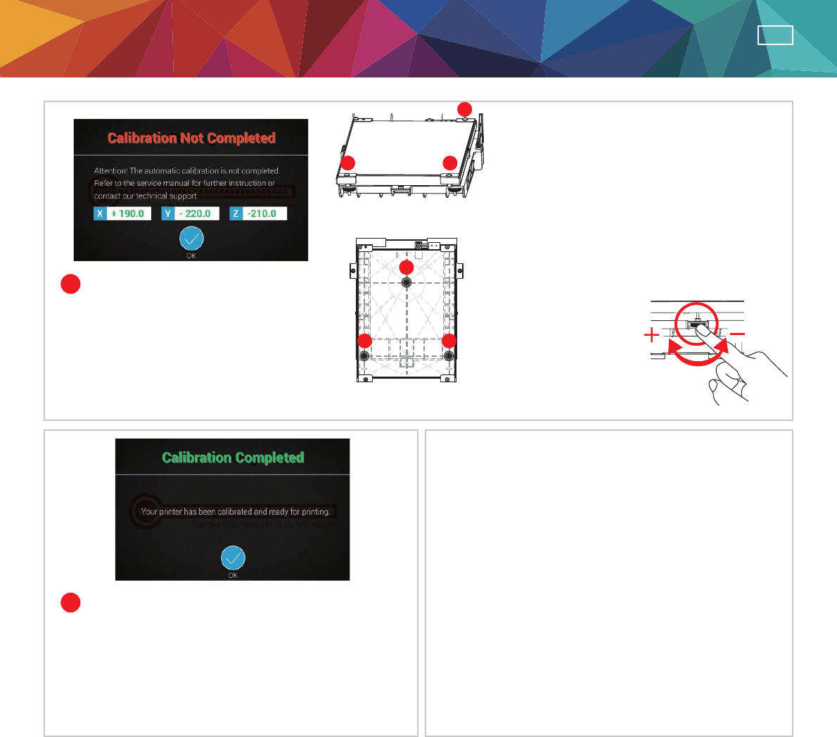
Refer to the values for adjustment
After the adjustment is finished, perform step
2. Wait until ADJUST SUCCESS is shown and
press OK to complete calibration.
If the value shown is always 999,999,999,
follow the steps below to clean.
A. Clean the surface of the print head using the
copper brush.
(Clean the contact point between the print head
and print bed)
B. Wipe and clean the measurement points in
reference with Figure 4.
C. Perform the calibration process again.
烋Reminder
I. Adjust the screw at Point A to reduce
the difference between the 1st and the
2nd measurements.
II.Adjust the screw at Point B based on
your evaluation of the results obtained
from the previous steps.
View the printer from the front when making
adjustment
Each turn leads to a
change of 50 to the
value shown
Rotate the screw to
the left to raise the bed
(value increases)
Rotate the screw to the
right to lower the bed
(value decreases)
4
5
;
<
=
Location of the
PHDVXUHPHQWSRLQWV
Adjust the location
of the screws
$%
&
Print Bed Adjustment Instructions

-10-
ENG
)RUIXUWKHULQIRUPDWLRQDQGLQVWUXFWLRQRIWKHVHUYLFHFRGHSOHDVHUHIHUWR;<=SULQWLQJZHEVLWH
KWWSVXSSRUW[\]SULQWLQJFRPRUFRQWDFWVHUYLFHFHQWHUIRUKHOS
Print Bed Adjustment Instructions
Service Code Display Panel Description
炵炵炵 Print bed heating error; critical temperature detected
炵炵炵炵 Extruder(s) heating error; critical temperature detected
炵炵炵 X axis motor failed results moving failed or X axis home sensor failed results home
detect failed
炵炵炵 Y axis motor failed results moving failed or Y axis home sensor failed results home
detect failed
炵炵炵 Z axis motor failed results moving failed or Z axis home sensor failed results home
detect failed
炵炵炵 Memory storage cannot read/write
炵炵炵 Flashrom cannot read/write
炵炵炵 Extruder or heated bed higher/lower than maximum/minimum temperature during printing
炵炵炵 Extruder cannot heat to the specified temperature
FCC Statement
This equipment has been tested and found to comply with the limits for a Class B digital device,
pursuant to part 15 of the FCC Rules. These limits are designed to provide reasonable protection
against harmful interference in a residential installation. This equipment generates, uses and can
radiate radio frequency energy and, if not installed and used in accordance with the instructions,
may cause harmful interference to radio communications. However, there is no guarantee that
interference will not occur in a particular installation. If this equipment does cause harmful
interference to radio or television reception, which can be determined by turning the equipment
off and on, the user is encouraged to try to correct the interference by one or more of the following
measures:
—Reorient or relocate the receiving antenna.
—Increase the separation between the equipment and receiver.
—Connect the equipment into an outlet on a circuit different from that to which the receiver is
connected.
—Consult the dealer or an experienced radio/TV technician for help.
FCC Radiation Exposure Statement
This device complies with FCC radiation exposure limits set forth for an uncontrolled environment
and it also complies with Part 15 of the FCC RF Rules. This equipment must be installed and operated
in accordance with provided instructions and the antenna(s) used for this transmitter must be installed
to provide a separation distance of at least 20 cm from all persons and must not be co-located or
operating in conjunction with any other antenna or transmitter. End-users and installers must be
provide with antenna installation instructions and consider removing the no-collocation statement.
This device complies with Part 15 of the FCC Rules. Operation is subject to the following two
conditions:
(1) this device may not cause harmful interference, and
(2) this device must accept any interference received, including interference that may cause
undesired operation.
Caution!
A
ny changes or modifications not expressly approved by the party responsible for compliance could
void the user's authority to operate the equipment.