XceedID XF2100C Multi-Tech Credential Reader User Manual
XceedID Corporation Multi-Tech Credential Reader Users Manual
XceedID >
Users Manual
Description
The Multi-technology Readers feature a rugged design and
can be installed almost anywhere. Durable, weatherproof,
UV-resistant materials, along with advanced electronics
and circuitry, protect readers against inclement weather
and exposure to sunlight.
Mounting the Reader
1. Find a suitable mounting position on the door frame or wall.
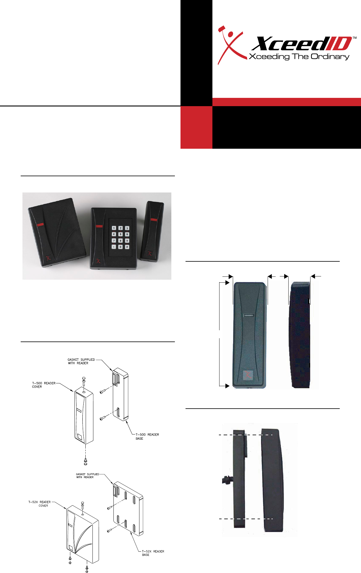
Note: For out of doors or wet locations, it is recommended
that the gasket provided be installed on the base as shown
in Figure 2.
2. Drill two mounting holes a minimum of 3.25” (82.6 cm)
apart on the mounting surface of the door frame or wall.
Refer to Figure 3.
3. Drill one .625” (1.587 cm) diameter hole in wall for the
pigtail wire connection.
4. Follow the cable connection chart. Connect power at the
panel when installation is complete.
5. Mount the base plate to the wall using the supplied screws.
6. Install gasket if required, see Figure 2.
7. Install top cover straight on to the reader base. Do not
force the cover on. The four cover guides should ensure
the connector seats correctly.
8. Verify the connection is secure and install the security
screws at the top and bottom of the reader.
9. Place a screw head cover over each of the screws. The
screw head cover should be flush with the reader once in
place.
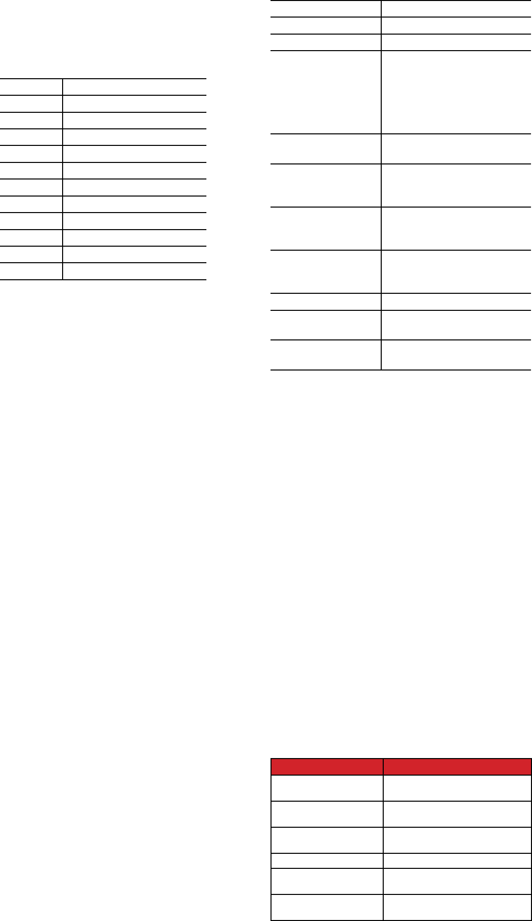
5.850 [148.6]
1.160
[29.5]
1.750
[44.5]
front view side view
XceedID Corporation
3899 Hancock Expressway
Security, CO 80911
Tel: 303-273-9930
Fax: 303-273-9937
www.xceedid.com
Multi-technology Readers
Installation Guide
Figure 1. Multi-technology Readers
Figure 2. Gasket Installation
Figure 3.
Figure 4. Aligning base plate and top cover
Specifications
The voltage specification for this reader is 8-16 VDC.
Higher voltage with the specifications provides better
performance and cable run distances.
The recommended cable gauge is 18-gauge to 22-gauge.
Check with the cable supplier to determine the best choice
for the application and installation distance.
FCC compliance
The FCC requires the following statement: This reader uses
radio frequency energy and has been tested, and complies
with the limits of FCC testing. Changes, modification,
or disregard of proper installation and instructions not
expressly approved by XceedID, and is strictly prohibited by
the FCC and could void the user’s authority to operate the
equipment.
a. This device complies with Industry Canada licence-exempt RSS
standard(s). Operation is subject to the following two conditions: (1)
this device may not cause interference, and (2) this device must accept
any interference, including interference that may cause undesired
operation of the device.
b. Le présent appareil est conforme aux CNR d’Industrie Canada
applicables aux appareils radio exempts de licence. L’exploitation est
autorisée aux deux conditions suivantes : (1) l’appareil ne doit pas
produire de brouillage, et (2) l’utilisateur de l’appareil doit accepter tout
brouillage radioélectrique subi, même si le brouillage est susceptible
d’en compromettre le fonctionnement.
Colors Black (standard), charcoal
Power supply Linear DC
Voltage range 8 - 16 VDC
Maximum and Average
Current range
XF2110C: 173 mA (max),
155mA (aver)
XF2100C: 157 mA (max),
141 mA (aver)
XF1100C: 132 mA(max),
116 mA (aver)
Temperature range -31 F to 149 F
-35 C to 65 C
Card read distance Distance can vary depending on
reader, installation conditions
and credential type.
Cable distance to panel 200 ft. max (22 gauge)
300 ft. max. (20 gauge)
500 ft. max. (18 gauge)
Wiegand output Up to 200 bits depending
on configuration and card
technology
Tamper output Open Collector
Regulatory approvals
and standards
UL, CE, and FCC (part 15)
ISO Standards ISO 14443A
ISO 15693
Ordering Information
Product Description
XF-1100-B
(Standard Black)
Mullion mount;
Wiegand output
XF-2100-B
(Standard Black)
1-Gang US mount;
Wiegand output
XF-2110-B
(Standard Black)
1-Gang US mount; Keypad; Wiegand
output
XF-1100-C (Charcoal) Mullion mount; Wiegand output
XF-2100-C (Charcoal) 1-Gang US mount;
Wiegand output
XF-2110-C (Charcoal) 1-Gang US mount; Keypad; Wiegand
output
Testing the Reader
1. Power up the reader. A red LED will light followed by a
beeper tone, which indicates the reader is ready.
2. Present a proper card, which has been programmed to
operate the reader.
* A green LED indicates a registered badge read.
* A red LED indicates idle (ready to read) state in the
Wiegand mode.
Removing the Cover
1. Remove the plugs and security screws.
2. Slide cover off perpendicular to base.
Trouble Shooting
1. If reader does not behave normally upon installation,
verify that cover and base are connected properly:
The reader is shipped unassembled. To assemble, pull cover
away from base and rotate until the connector port on
the base is aligned with the connector port on the cover.
Snap shut.
2. Only connect wires necessary for use. Cut and/or isolate
unused wires. Connecting unnecessary wires may lead to
unexpected reader behavior.
3. If multiple reader units are installed in close proximity or
back to back, RF interference may result in reduced read
range performance.
4. A recurrent triple beep audio sequence may indicate
that the cover is not seated properly. Remove cover and
check for bent or broken pins in the connector.
Copyright © 2007-2011, XceedID. All rights reserved. Revised 2/1/2011.
Connecting the Cable
1. The readers are supplied with a 12-conductor cable
pigtail. Ensure the reader wiring is disconnected at the
host panel until all connections are made at the reader.
Use the cable connection chart below:
2. Use a DC Power source between 8-16 volts.
3. Verify the reader is properly grounded by attaching the
ground wire to an earth ground connection at the power
supply or panel end of the cable.
Yellow Beeper
Blue Hold
Purple Future
Green Wiegand Data 0 or RS485A
White Wiegand Data 1 or RS485A
Orange Green LED
Brown Red LED
Red Power + DC (6-16 VDC)
Black Ground
Pink Not Used
Gray Not Used
Drain Shield Ground