Xircom An Intel GEM3501 Core Engine, PCS-1900 GSM Radio Module User Manual Core Engine Developer Guide
Xircom, An Intel Company Core Engine, PCS-1900 GSM Radio Module Core Engine Developer Guide
Contents
- 1. Core Engine Approvals Guide
- 2. Core Engine Developers Guide
Core Engine Developers Guide

© 2001 Xircom, Inc., an Intel company All rights reserved.
All trademarks and copyrights are the property of Xircom, Inc., an Intel company
Core Engine
GSM/GPRS Wireless Terminal
Developer Guide
(Preliminary Draft – 7/6/2001)
C
Co
on
nf
fi
id
de
en
nt
ti
ia
al
l

Core Engine GSM/GPRS Modem Developer Guide Preliminary Draft: 7/6/2001 2
Part Number: 07100026, Revision: 002 Confidential
© 2001 Xircom, Inc., an Intel company All rights reserved.
All trademarks and copyrights are the property of Xircom, Inc., an Intel company
1
1
R
RE
EV
VI
IS
SI
IO
ON
N
H
HI
IS
ST
TO
OR
RY
Y
Date Revision Description
3/20/01 001 Initial revision (preliminary).
7/6/01 002 Added Core Engine RF antenna connector information.
Added information on antenna design considerations.
Added Core Engine 60-pin I/O connector pin-out information.
Updated Carrier Board section for Rev B carrier board.
Updated information in Detailed Specifications section.
Removed reference to dual-band 900/1800 version.
Added the following new sections:
- Power (requirements; management; etc.).
- Serial communications (single vs dual ports, XGAP, etc.).
- Audio (mic & speaker interface; audio path selection;
cabling; etc.).
- Updating the Core Engine firmware.

Core Engine GSM/GPRS Modem Developer Guide Preliminary Draft: 7/6/2001 3
Part Number: 07100026, Revision: 002 Confidential
© 2001 Xircom, Inc., an Intel company All rights reserved.
All trademarks and copyrights are the property of Xircom, Inc., an Intel company
2
2
S
SA
AF
FE
ET
TY
Y
P
PR
RE
EC
CA
AU
UT
TI
IO
ON
NS
S
2.1 Important Safety Information
Some of the following information may not apply to all devices described in this manual.
However, precautions should be observed when handling any electrical device.
! Save this manual, it contains important safety information and operating instructions.
! Do not expose the Core Engine product to open flames.
! Care should be taken so that liquids do not spill into the devices.
! A qualified electrician should perform all primary connections to AC power.
! Do not attempt to disassemble the product. Doing so will void the warranty. With the
exception of Subscriber Identification Modules (SIM), this product does not contain
consumer serviceable components.
2.2 Guidelines for Limiting RF Exposure
The Core Engine products are GSM radio transceivers.
The following installation and operation restrictions apply to the all Core Engine products:
! A separation distance of at least 20 cm (7 7/8) inches between the antenna and body of
the user and other persons must be maintained at all times
! In FIXED applications using a 1900Mhz Core Engine antenna gain* is limited to a
maximum of 7 dBi, with a corresponding equivalent isotropic radiated power (EIRP) of 37
dBm / 5 W
! In MOBILE applications using a 1900Mhz Core Engine antenna gain* is limited to a
maximum of 3 dBi, with a corresponding equivalent isotropic radiated power (EIRP) of 33
dBm / 3 W
! Desktop and other uses of these devices where the antenna can easily be relocated are
considered by the FCC to be mobile applications.
* Antenna gain is defined as gain in dBi (dB referenced to an isotropic radiator) minus cabling loss.
NOTE: Additional care must be taken by the installer and/or user of the Core Engine
products to ensure proper antenna selection and installation. Adherence to the
above conditions is necessary to comply with FCC requirements for safe operation
regarding exposure to RF radiation.
2.3 Disclaimer
The information and instructions contained within this publication comply with all
FCC, NRLT, IMEI and other applicable codes in effect at the time of publication.
Xircom, Inc. disclaims all responsibility for any act, or breach of law, code or
regulation, including local or state codes, performed by a third party.

Core Engine GSM/GPRS Modem Developer Guide Preliminary Draft: 7/6/2001 4
Part Number: 07100026, Revision: 002 Confidential
© 2001 Xircom, Inc., an Intel company All rights reserved.
All trademarks and copyrights are the property of Xircom, Inc., an Intel company
Xircom, Inc., an Intel company (hereafter “Xircom”) strongly recommends that all
installations, hookups, transmissions, etc. be performed by persons who are
experienced in the fields of radio frequency technologies. Xircom acknowledges that
the installation, setup and transmission guidelines contained within this publication
are guidelines, and that each installation may have variables outside of the
guidelines contained herein. Said variables must be taken into consideration when
installing or using the product, and Xircom, Inc. shall not be responsible for
installations or transmissions that fall outside of the parameters set forth in this
publication.
Xircom shall not be liable for consequential or incidental damages, injury to any
person or property, anticipated or lost profits, loss of time, or other losses incurred
by Customer or any third party in connection with the installation of the Products or
Customer's failure to comply with the information and instructions contained herein.
2.4 Beta Release Notes
The information in this document is preliminary and subject to change by Xircom.
2.4.1 Data Services
The current software release does not support USSD or Group 3 Fax. These services will
be added in subsequent versions.
2.4.2 AT Commands
The current software version may not support all AT commands listed in this document.
Please reference the Core Engine Programmer Reference document for details of the
software AT command implementation.
2.4.3 PUK Procedure
The PUK procedure outlined in this document will be changing.
Core Engine GSM/GPRS Modem Developer Guide Preliminary Draft: 7/6/2001 5
Part Number: 07100026, Revision: 002 Confidential
© 2001 Xircom, Inc., an Intel company All rights reserved.
All trademarks and copyrights are the property of Xircom, Inc., an Intel company
T
TA
AB
BL
LE
E
O
OF
F
C
CO
ON
NT
TE
EN
NT
TS
S
1 REVISION HISTORY ....................................................................................................2
2 SAFETY PRECAUTIONS.............................................................................................3
2.1 Important Safety Information........................................................................................ 3
2.2 Guidelines for Limiting RF Exposure............................................................................ 3
2.3 Disclaimer.................................................................................................................... 3
2.4 Beta Release Notes..................................................................................................... 4
2.4.1 Data Services....................................................................................................... 4
2.4.2 AT Commands..................................................................................................... 4
2.4.3 PUK Procedure.................................................................................................... 4
3 PRODUCT OVERVIEW................................................................................................9
3.1 GSM Overview ............................................................................................................ 9
3.2 Model Variation............................................................................................................ 9
3.3 General Description..................................................................................................... 9
3.4 Summary of the Features for the Core Engine modem...............................................10
3.5 Programmer Reference ..............................................................................................10
3.6 Backward Compatibility...............................................................................................10
3.7 Modes of Operation ....................................................................................................11
3.7.1 Circuit Switched Data..........................................................................................11
3.7.2 Transparent and Non Transparent Transmissions...............................................11
3.7.3 Short Message Service .......................................................................................11
3.7.4 Voice...................................................................................................................12
3.7.5 General Packet Radio Service (GPRS)...............................................................12
4 CARRIER BOARD......................................................................................................13
4.1 Core Engine Modem I/O Interface [P4] .......................................................................13
4.2 Core Engine I/O Signal Header [J4]............................................................................17
4.3 Ground Points [J2, J9] ................................................................................................17
4.4 RF Antenna Connector [J5, J6]...................................................................................17
4.5 Power [J7, J8, J10] ....................................................................................................17
4.6 Primary Serial Interface [P3] .......................................................................................18
Core Engine GSM/GPRS Modem Developer Guide Preliminary Draft: 7/6/2001 6
Part Number: 07100026, Revision: 002 Confidential
© 2001 Xircom, Inc., an Intel company All rights reserved.
All trademarks and copyrights are the property of Xircom, Inc., an Intel company
4.7 Secondary Serial Interface [P2] ..................................................................................18
4.8 Primary Audio Interface [P1].......................................................................................19
4.9 Secondary Audio Interface [J1]...................................................................................20
4.10 Audio Interface Select [JP2]......................................................................................20
4.11 Subscriber Interface Module [J3] ..............................................................................20
4.12 Status Indication [DS1] .............................................................................................20
5 POWER.......................................................................................................................22
5.1 Power Up Sequence...................................................................................................22
5.2 Power Management....................................................................................................22
5.2.1 Power Modes......................................................................................................22
5.2.2 Hardware Signals................................................................................................24
5.2.3 Software Commands...........................................................................................24
5.3 Transmit Power ..........................................................................................................25
6 SERIAL COMMUNICATIONS ....................................................................................26
6.1 Supported Serial Port Configurations..........................................................................26
6.1.1 Single Port Configuration ....................................................................................26
6.1.2 Dual Port Configuration.......................................................................................27
7 AUDIO.........................................................................................................................29
7.1 Audio Path Selection ..................................................................................................29
7.1.1 Hardware Selection of Audio Path.......................................................................29
7.1.2 Software Selection of Audio Path........................................................................29
7.2 Microphone Input........................................................................................................29
7.3 Speaker Output ..........................................................................................................30
7.4 Audio Circuit Implementation......................................................................................31
7.4.1 Example Single-Ended Microphone Circuit .........................................................31
7.4.2 Example Differential Microphone Circuit..............................................................32
7.5 Microphone Cable Considerations..............................................................................32
8 RF ANTENNA.............................................................................................................33
8.1 Antenna Connector.....................................................................................................33
8.2 Antenna Selection.......................................................................................................33
8.3 Antenna Performance Guidelines ...............................................................................33
8.3.1 Antenna Impedance Match .................................................................................33
8.3.2 Antenna Pattern and Gain...................................................................................34
8.3.3 Antenna Beam Width ..........................................................................................34
Core Engine GSM/GPRS Modem Developer Guide Preliminary Draft: 7/6/2001 7
Part Number: 07100026, Revision: 002 Confidential
© 2001 Xircom, Inc., an Intel company All rights reserved.
All trademarks and copyrights are the property of Xircom, Inc., an Intel company
8.3.4 Antenna Polarization ...........................................................................................35
8.4 Antenna Location and Network Communication .........................................................35
9 PROVISIONING THE SIM ..........................................................................................36
9.1 GSM Services Supported by the Core Engine modem................................................36
9.2 Selecting the Modes of Operation...............................................................................36
10 INSTALLATION & INITIALIZATION.........................................................................37
10.1 Installation and Verification.......................................................................................37
10.1.1 Installation.........................................................................................................37
10.1.2 Verification ........................................................................................................38
10.2 SMS Message Verification........................................................................................41
10.2.1 Modem Sent SMS (Text)...................................................................................41
10.2.2 Modem RECEIVE SMS (Text)...........................................................................44
10.2.3 SIM Data Provisioning Verification (Optional)....................................................44
10.2.4 Match Modem Serial port to CPE......................................................................44
10.2.5 Verify Setup ......................................................................................................44
10.2.6 Connect Primary Serial Port Cable....................................................................44
10.3 Final Verification .......................................................................................................45
10.3.1 SMS Verification................................................................................................45
11 DETAILED SPECIFICATIONS .................................................................................46
11.1 Physical Dimensions and Weight..............................................................................46
11.2 Operating Power.......................................................................................................46
11.2.1 Transmit Power.................................................................................................46
11.2.2 Receiver Sensitivity...........................................................................................47
11.3 Care and Maintenance..............................................................................................47
12 ENVIRONMENTAL SPECIFICATIONS....................................................................48
12.1 Climatic.....................................................................................................................48
12.1.1 Climatic: Operational.........................................................................................48
12.1.2 Climatic: Storage and Transportation ................................................................48
12.2 Mechanical ...............................................................................................................48
12.2.1 Mechanical: Operational....................................................................................48
12.2.2 Mechanical: Storage and Transportation...........................................................48
12.2.3 Mechanical: Proposed Standards......................................................................49
12.3 Electromagnetic........................................................................................................49
12.3.1 Electromagnetic Emissions ...............................................................................49
12.3.2 Electromagnetic Immunity.................................................................................49
13 GLOSSARY AND ACRONYMS ...............................................................................50
Core Engine GSM/GPRS Modem Developer Guide Preliminary Draft: 7/6/2001 8
Part Number: 07100026, Revision: 002 Confidential
© 2001 Xircom, Inc., an Intel company All rights reserved.
All trademarks and copyrights are the property of Xircom, Inc., an Intel company
14 UPDATING THE CORE ENGINE FIRMWARE.........................................................53
14.1 Required Files ..........................................................................................................53
14.2 Download Utility........................................................................................................53
14.3 Download Procedure ................................................................................................54
15 INSTALLING A REMOTE ANTENNA ......................................................................56
15.1 Antenna Coaxial Cable and Connectors ...................................................................56
15.2 Outdoor Antenna Grounding.....................................................................................56
15.3 Coaxial Cable Routing..............................................................................................56
15.4 Coaxial Cable Losses and Lengths...........................................................................57
15.5 Formula Examples....................................................................................................59
15.5.1 Example 1:........................................................................................................59
15.5.2 Example 2:........................................................................................................59
15.5.3 Example 3:........................................................................................................59
Core Engine GSM/GPRS Modem Developer Guide Preliminary Draft: 7/6/2001 9
Part Number: 07100026, Revision: 002 Confidential
© 2001 Xircom, Inc., an Intel company All rights reserved.
All trademarks and copyrights are the property of Xircom, Inc., an Intel company
3 P
PR
RO
OD
DU
UC
CT
T
O
OV
VE
ER
RV
VI
IE
EW
W
The Core Engine modem is a compact, wireless modem that utilizes the international
standard Global System for Mobile communications (GSM). The device enables low-cost,
application-specific, two-way communication and control. It takes full advantage of GSM
capabilities such as Subscriber Identity Modules (SIM), which are "smart cards" that
provides numerous advantages.
Over-the-air communication lets the Core Engine accomplish tasks that previously
required on-site visits and offers innovative new service capabilities never before
available. In addition, terminal authentication and data encryption ensures a more
confidential communication link between the terminal user and the data recipient.
3.1 GSM Overview
The GSM communications standard, already widely deployed in Europe, Asia, and North
America, overcomes many of the drawbacks found in other wireless telemetry
approaches. The GSM communications network was designed from the ground up, for
reliable and inexpensive digital data transfers.
The GSM network employs integrated data and data-friendly capabilities such as short
message services, circuit switched data and, soon, GPRS, which brings the best of
wireless and packet data into harmony and will make new services even more practical
and affordable. In many countries around the world, especially in Western Europe, GSM-
based networks are the only digital networks deployed.
The Core Engine modem leverages existing public GSM networks, as opposed to other
systems that require the utility to build, operate, and maintain expensive private wireless
networks.
3.2 Model Variation
The Core Engine modem supports GSM Short message service (SMS), voice, and circuit
switched data (transparent and non-transparent mode) up to 9.6 Kbps. This modem also
is GPRS hardware ready. It provides GPRS packet data up to and including Class 10, in
addition to Short Message Service (SMS), voice, and circuit switched data (transparent
and non-transparent mode) up to 9.6 Kbps.
! Core Engine modems are available in the following configuration:
! 1900 MHz: Part # 4200-1100
3.3 General Description
The Core Engine Carrier Board assembly provides DC to DC conversion and standard
interface connections with drivers for two serial interfaces, a voice interface, and DC
power.
The modem operates under a wide range of DC input power. Communication is through
an RS-232 physical interface, using the GSM - AT command set.

Core Engine GSM/GPRS Modem Developer Guide Preliminary Draft: 7/6/2001 10
Part Number: 07100026, Revision: 002 Confidential
© 2001 Xircom, Inc., an Intel company All rights reserved.
All trademarks and copyrights are the property of Xircom, Inc., an Intel company
3.4 Summary of the Features for the Core Engine modem
Primary serial port V.24 protocol, 3V levels.
Secondary serial port Secondary 3V serial port (currently restricted to debug use).
Voice Supports two (2) vocoder modes: full-rate, and enhanced full-rate
(EFR).
Antenna On-board microminiature coaxial connector for RF antenna.
Command protocol AT command set.
Interface
Subscriber Identification Module
(SIM)
3V mini-SIM carrier and interface on carrier board.
Electrical power Fixed DC voltage 3.7V +/-0.3V
Power
Peak currents and average power
dissipation
Refer to the Operating Power table in the Technical Specifications
section for peak currents and average power dissipation for various
modes of operation.
Frequency bands PCS 1900 capability.
Radio Features
GSM features supported Provides for all GSM authentication, encryption, and frequency
hopping algorithms.
Regulatory Agency approvals # GSM Type Approval – planned
# FCC Certification (Part 24) – planned
# CE (European Community Certification) – planned
# IC (Industry Canada) – planned
GSM
Functionality
# Mobile-originated and mobile-terminated SMS messages: up to 140 bytes or up to 160 GSM 7-bit
ASCII characters.
# Reception of Cell Broadcast Message.
# SMS Receipt acknowledgement.
# Circuit Switched Data (Transparent & Non-transparent programmable from 4.8 to 9.6 Kbps).
# Voice.
# Supports GSM Phase 2+.
GPRS
Functionality
GPRS software will be available at a later date.
Table 1: Core Engine Summary of Features
3.5 Programmer Reference
For greater flexibility that enhances the usability of the Core Engine modems, Xircom
provides a Core Engine Programmer Reference. This document goes into greater detail,
in an easy to read format, on the enhanced programming capabilities specific to the Core
Engine modem, including details of supported AT commands.
3.6 Backward Compatibility
GSM functionality is forever evolving. Subsequently, in order to maintain the highest
standards, the Core Engine modems will be backward compatible with new GSM
functionality such as General Packet Radio Service (GPRS). Applications supported with
Core Engine GSM/GPRS Modem Developer Guide Preliminary Draft: 7/6/2001 11
Part Number: 07100026, Revision: 002 Confidential
© 2001 Xircom, Inc., an Intel company All rights reserved.
All trademarks and copyrights are the property of Xircom, Inc., an Intel company
early current versions of the modem will continue to be supported, as GSM technology
evolves to GPRS, and then on to third generation technologies, which are now in the
process of standardization and development.
3.7 Modes of Operation
Core Engine offers several modes of operation to address a variety of application
requirements.
3.7.1 Circuit Switched Data
Circuit switched data is the most widespread and traditional means of data and voice
transmission available today. A circuit switched connection occupies one network line for
the entire length of data transmission and during this time, no other user may access this
network line. A circuit switched connection is the optimal means for transmitting any
continuous amount of data, such as video transmission or voice.
A common example of a circuit switched network is the public telephone system. When
person A picks up the telephone and dials the number of person B, the network
determines and assigns a path for that transmission. The signal travels through each
assigned circuit switch to complete the connection.
Once the signal has reached person B, a continuous two-way transmission path has been
established. On a long distance call, for example, many circuits would need to be
connected together to make the call possible. These circuits are dedicated to the call for
the duration of the transmission and cannot be shared by other users. This requires
substantial network resources to be allocated per user.
3.7.2 Transparent and Non Transparent Transmissions
GSM provides two connection modes of transmission: transparent and non-transparent.
All Core Engine models support both modes. The transparent data mode delivers a
service with a variable error rate, with a guaranteed throughput and delay, whereas the
non-transparent mode delivers a constantly low forward error correction rate, but with a
non-guaranteed throughput or delay.
Not all networks support transparent services.
The non-transparent service delivers the most reliable performance and is closest to using
a modem over a fixed telephone line.
3.7.3 Short Message Service
To accommodate smaller messages, GSM uses short message service (SMS) for efficient
and timely data transmission and data retrieval. SMS is a point-to-point, storage and
forwarding, message service that is used in data transmissions such as paging,
notification, news flashes, and information retrieval.
Short messages can carry up to 140 8-bit characters. (160, 7-bit characters available –
refer to the Core Engine Programmer Reference for configuration)
Short Messages can be sent and received simultaneously with a voice or data call and
are sent above the voice or data in the overhead-signaling path (Traffic & Bearer).
Although similar in concept to traditional paging, the primary difference is that SMS is not
geographically restricted as paging systems are. Moreover, the GSM network stores and
resends the message if the receiver’s handset is turned off (In some cases, if a pager is
turned off, the message is simply lost).
Core Engine GSM/GPRS Modem Developer Guide Preliminary Draft: 7/6/2001 12
Part Number: 07100026, Revision: 002 Confidential
© 2001 Xircom, Inc., an Intel company All rights reserved.
All trademarks and copyrights are the property of Xircom, Inc., an Intel company
Listed below are the essential characteristics and assumptions regarding the form of SMS
supported by the Core Engine modem.
! Support of both mobile originated and mobile terminated SMS.
! 8-bit data in PDU mode
! Message Class 1
! Up to 140 ASCII characters per message using 8-bit data mode. (160 characters if
7bit GSM ASCII used)
! Notify the network when it has memory capacity available to receive one or more
SMS messages after it has previously rejected a message because its memory
capacity was exceeded
3.7.4 Voice
The Core Engine modem has full voice capabilities, provided the necessary connections
have been made for the speaker and microphone pins on the 60-pin I/O connector. The
AT commands and their responses allow the user to enter and receive information from
the Core Engine modem. These functions include the ability for dialing, for providing on-
hook or off-hook, and for controlling other aspects of the voice call interface.
The Core Engine modem supports two (2) vocoder compression algorithms for voice
communication: full-rate and enhanced full-rate (EFR)
3.7.5 General Packet Radio Service (GPRS)
GPRS is the next step in GSM data services: a fully packet-based protocol service with
direct access to the Internet. By bringing the best features of messaging, circuit-switched
services, and packet data into harmony, GPRS promises to make new applications even
more practical and affordable. Future releases of the Core Engine modem will support
GPRS mode. Currently, the Core Engine modem is hardware-ready for GPRS.
Core Engine GSM/GPRS Modem Developer Guide Preliminary Draft: 7/6/2001 13
Part Number: 07100026, Revision: 002 Confidential
© 2001 Xircom, Inc., an Intel company All rights reserved.
All trademarks and copyrights are the property of Xircom, Inc., an Intel company
4
4
C
CA
AR
RR
RI
IE
ER
R
B
BO
OA
AR
RD
D
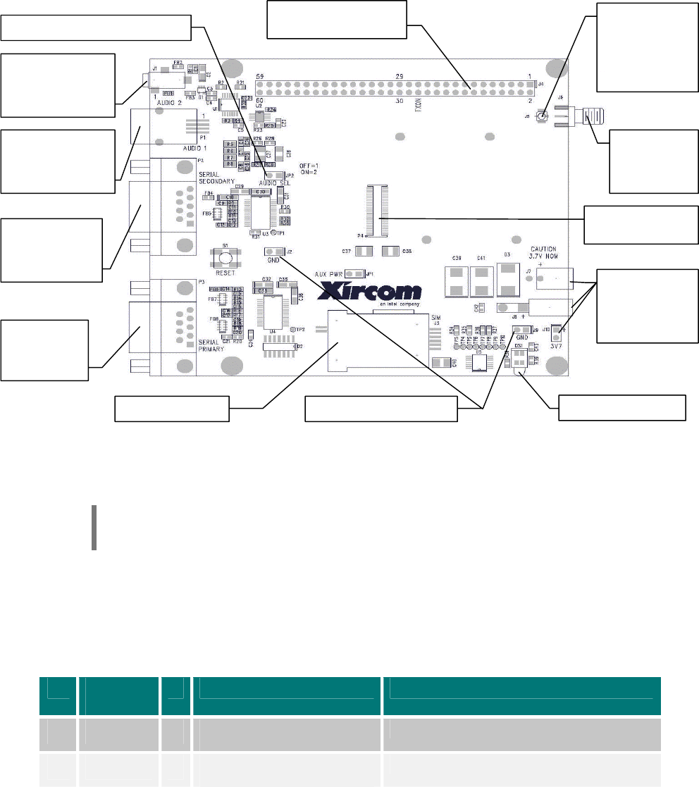
Figure 1: Core Engine Carrier Board (Rev B)
NOTE: The carrier board is intended for development only, and is not suitable for
performing RF qualification.
4.1 Core Engine Modem I/O Interface [P4]
The Core Engine modem connects to the carrier board using a 60-pin connector
(connector P4 on the carrier board). The I/O interface signals are described in Table 2.
Pin Signal
Name
I/O Functionality Parameters
1 VCC * • 0.5A per contact maximum
current per contact. • Vin= 3.7 +/- 0.3 Volt
2 VCC * • 0.5A per contact maximum
current per contact. • Vin= 3.7 +/- 0.3 Volt
[P4] Core Engine
I/O connector.
[J3] SIM holder.
[JP2] Audio port select jumper.
[P2] DB-9 for
secondary
serial port.
[P3] DB-9
for primary
serial port.
[J7, J8, J10]
Power
3.7V (+/-0.3V).
[DS1] Status LED.
[J5] Connector
for cable to
Core Engine
RF antenna
connector.
[P1] RJ-9 for
primary audio port
(differential).
[J4] Header access to
Core En
g
ine I/O
p
ins.
[J6] SMA RF
antenna
connector.
[J1] Secondary
audio port (single-
ended).
[J2, J9] GND ref points.

Core Engine GSM/GPRS Modem Developer Guide Preliminary Draft: 7/6/2001 14
Part Number: 07100026, Revision: 002 Confidential
© 2001 Xircom, Inc., an Intel company All rights reserved.
All trademarks and copyrights are the property of Xircom, Inc., an Intel company
Pin Signal
Name
I/O Functionality Parameters
3 VCC * • 0.5A per contact maximum
current per contact. • Vin= 3.7 +/- 0.3 Volt
4 VCC * • 0.5A per contact maximum
current per contact. • Vin= 3.7 +/- 0.3 Volt
5 VCC * • 0.5A per contact maximum
current per contact. • Vin= 3.7 +/- 0.3 Volt
6 VCC * • 0.5A per contact maximum
current per contact. • Vin= 3.7 +/- 0.3 Volt
7 GND * • (0V)
8 GND * • (0V)
9 SPK_N1 O • Differential output
• Speaker 1 (primary)
• Differential output voltage typ. 3.7V
• Output differential max. DC offset 100mV
• Differential output load resistance min. 15 Ohm
• Output load capacitance max. 4700pF
10 BATT_LOW O • Active low when BATT
voltage is <= 3.4V • Vol min = 0V Vol max = 0.2V
• Voh min = 2.28V Voh max = 2.53V
11 GND * • (0V)
12 CTS_2 O • Flow control
• 2nd port (DCE)
• Clear to Send
• Vol min = 0V Vol max = 0.2V
• Voh min = 2.28V Voh max = 2.53V
13 SPK_P1 O • Differential output
• Speaker 1 (primary)
• Differential output voltage typ. 3.7V
• Output differential max. DC offset 100mV
• Differential output load resistance min. 15 Ohm
• Output load capacitance max. 4700pF
14 GPIO0 IO • GPIO • Vil min = -0.3V Vil max = 0.496V
• Vih min = 1.771V Vih max = 3.3V
• Vol min = 0V Vol max = 0.2V
• Voh min = 2.28V Vol max = 2.53V
15 GND * • (0V)
16 RTS_2 I • Flow control.
• 2nd port (DCE)
• Request to Send
• Vol min = 0V Vol max = 0.2V
• Voh min = 2.28V Voh max = 2.53V
17 VMIC O • Bias voltage output for Mic(s) • Vmic Typ = 1.8V, min. = 1.6V
• Current 2mA
18 RESET_B I • Reset Baseband
• Active Low
• Vil min = -0.3V Vil max = 0.496V
• Vih min = 1.771V Vih max = 3.3V
19 GND * • (0V)
20 RINGER O • External ringer function • Vol min = 0V Vol max = 0.2V
• Voh min = 2.28V Voh max = 2.53V
21 MIC_N1 I • Differential input
• MIC 1 (primary)
• Input voltage differential 1.03Vpp
• Differential input resistance typ. 50Kohm

Core Engine GSM/GPRS Modem Developer Guide Preliminary Draft: 7/6/2001 15
Part Number: 07100026, Revision: 002 Confidential
© 2001 Xircom, Inc., an Intel company All rights reserved.
All trademarks and copyrights are the property of Xircom, Inc., an Intel company
Pin Signal
Name
I/O Functionality Parameters
• Input capacitance typ. 5pF
22 PWR_DWN I • Active low input bring the unit
down like CPWROFF • Vil min = -0.3V Vil max = 0.496V
• Vih min = 1.771V Vih max = 3.3V
23 GND * • (0V)
24 GND * • (0V)
25 MIC_P1 I • Differential input
• MIC 1 (primary)
• Input voltage differential 1.03 Vpp
• Differential input resistance typ. 50Kohm
• Input capacitance typ. 5pF
26 TXON O • Transmitter on
• Active High
• Vol min = 0V Vol max = 0.2V
• Voh min = 2.28V Voh max = 2.53V
27 GND *
28 GPIO1 IO • GPIO • Vil min = -0.3V Vil max = 0.496V
• Vih min = 1.771V Vih max = 3.3V
• Vol min = 0V Vol max = 0.2V
• Voh min = 2.28V Vol max = 2.53V
29 RX_2 O • Check your Rx/Tx direction
• Core Engine is DCE
• Vol min = 0V Vol max = 0.2V
• Voh min = 2.28V Voh max = 2.53V
30 AUDIO_EN O • Active high when audio circuit
should be enabled
• Can be used by a customer
to go into power savings
mode on their audio circuit.
• Vol min = 0V Vol max = 0.2V
• Voh min = 2.28V Voh max = 2.53V
31 TX_2 I • Check your Rx/Tx direction
• Core is DCE
• Vil min = -0.3V Vil max = 0.496V
• Vih min = 1.771V Vih max = 3.3V
32 SLEEP O • Indication when RF section is
asleep
• Active Low
• Vol min = 0V Vol max = 0.2V
• Voh min = 2.28V Voh max = 2.53V
33 GND * • (0V)
34 AUDIO_SEL I • Selection between
Primary/Secondary audio
port
• Active low
• High=Primary,
Low=Secondary
• Vil min = -0.3V Vil max = 0.496V
• Vih min = 1.771V Vih max = 3.3V
35 LED0_RMT O • Used for driving LED (Red)
• Active High
• Vol min = 0V Vol max = 0.2V
• Voh min = 2.28V Voh max = 2.53V
36 SPK_N2 O • Differential output
• Speaker 2 (secondary)
• Differential output voltage typ. 3.7V
• Output differential max. DC offset 100mV
• Differential output load resistance min. 15 Ohm
• Output load capacitance max. 4700pF.
37 LED1_RMT O • Used for driving LED (Green)
• Active High
• Vol min = 0V Vol max = 0.2V
• Voh min = 2.28V Voh max = 2.53V
38 SPK_P2 O • Differential output • Differential output voltage typ. 3.7V

Core Engine GSM/GPRS Modem Developer Guide Preliminary Draft: 7/6/2001 16
Part Number: 07100026, Revision: 002 Confidential
© 2001 Xircom, Inc., an Intel company All rights reserved.
All trademarks and copyrights are the property of Xircom, Inc., an Intel company
Pin Signal
Name
I/O Functionality Parameters
• Speaker 2 (secondary) • Output differential max. DC offset 100mV
• Differential output load resistance min. 15 Ohm
• Output load capacitance max. 4700pF.
39 WAKE_UP I • Wake up request if baseband
is asleep
• Active Low
• Vil min = -0.3V Vil max = 0.496V
• Vih min = 1.771V Vih max = 3.3V
40 MIC_N2 I • Differential input
• MIC 2 (secondary)
• Input voltage differential 1.03Vpp
• Differential input resistance typ. 50Kohm
• Input capacitance typ. 5pF
41 GND * • (0V)
42 MIC_P2 I • Differential input
• MIC 2 (secondary)
• Input voltage differential 1.03 Vpp
• Differential input resistance typ. 50Kohm
• Input capacitance typ. 5pF
43 RX_1 O • Check your Rx/Tx direction
• 1st port
• Core is DCE
• Vol min = 0V Vol max = 0.2V
• Voh min = 2.28V Voh max = 2.53V
44 GND * • (0V)
45 DSR_1 O • Core is DCE
• Data Set Ready (DSR)
• Vol min = 0V Vol max = 0.2V
• Voh min = 2.28V Voh max = 2.53V
46 TBAT I • Thermistor voltage divider
input (NTC) • T.B.D.
47 DCD_1 O • Core is DCE
• Data Carrier Detect (DCD)
• Vol min = 0V Vol max = 0.2V
• Voh min = 2.28V Voh max = 2.53V
48 SIM_CLK O • SIM • T.B.D.
49 RI_1 O • Core is DCE
• Ring Indicator (RI)
• Indicates incoming circuit
switched data or voice call.
• Vol min = 0V Vol max = 0.2V
• Voh min = 2.28V Voh max = 2.53V
50 GND * • (0V)
51 TX_1 I • Check your Rx/Tx direction
• 1st port
• Core is DCE
• Vil min = -0.3V Vil max = 0.496V
• Vih min = 1.771V Vih max = 3.3V
52 SIM_IO IO • SIM • T.B.D.
53 RTS_1 I • Flow control
• 1st port (DCE)
• Request To Send (RTS)
• Vil min = -0.3V Vil max = 0.496V
• Vih min = 1.771V Vih max = 3.3V
54 SIM_RST O • SIM • T.B.D.
55 CTS_1 O • Flow control
• 1st port (DCE)
• Clear To Send (CTS)
• Vol min = 0V Vol max = 0.2V
• Voh min = 2.28V Voh max = 2.53V

Core Engine GSM/GPRS Modem Developer Guide Preliminary Draft: 7/6/2001 17
Part Number: 07100026, Revision: 002 Confidential
© 2001 Xircom, Inc., an Intel company All rights reserved.
All trademarks and copyrights are the property of Xircom, Inc., an Intel company
Pin Signal
Name
I/O Functionality Parameters
56 SIM_GND O • SIM • GND
57 DTR_1 I • Core is DCE
• Data Terminal Ready (DTR)
• Vil min = -0.3V Vil max = 0.496V
• Vih min = 1.771V Vih max = 3.3V
58 SIM_VCC O • SIM • T.B.D.
59 GND * • (0V)
60 GND * • (0V)
Table 2: Core Engine I/O Connector Pin Out
4.2 Core Engine I/O Signal Header [J4]
The Core Engine I/O signals can be accessed externally at a 60-pin header (connector J4
on the carrier board). The I/O interface signals are described in Table 2.
4.3 Ground Points [J2, J9]
Two ground points are provided (J2 and J9 on the carrier board) which can be used for
any probe hookup, for example to an oscilloscope.
4.4 RF Antenna Connector [J5, J6]
The RF antenna may be connected to the Core Engine modem directly, or to the carrier
board (at connector J6). When connecting the RF antenna to the carrier board, a cable
must also be connected from the carrier board (at connector J5) to the RF connector on
the Core Engine board.
The Core Engine board uses a muRata Microminiature SMT Coaxial Connector (muRata
p/n “MM9329-2700”) for RF antenna connection.
The carrier board uses an SMA connector for connection to an antenna, and a muRata
Microminiature SMT Coaxial Connector (muRata p/n “MM9329-2700”) for connection to
the Core Engine board RF connector.
The Core Engine modem is designed to support interchangeable antenna types, provided
that each antenna has 50-ohm impedance and has been tuned to the frequency band
intended.
4.5 Power [J7, J8, J10]
The Core Engine carrier board requires an input voltage of 3.7 VDC +/- 0.3V (connectors
J7, J8 & J10 on the carrier board).
CAUTION: The carrier board powers the Core Engine board directly, and so must be
used with a 3.7V (+/- 0.3V) power supply only.

Core Engine GSM/GPRS Modem Developer Guide Preliminary Draft: 7/6/2001 18
Part Number: 07100026, Revision: 002 Confidential
© 2001 Xircom, Inc., an Intel company All rights reserved.
All trademarks and copyrights are the property of Xircom, Inc., an Intel company
4.6 Primary Serial Interface [P3]
The primary serial I/O interface (connector P3 on the carrier board) implements RS-232
using a DB-9 connector and supports auto baud capability from 2400 bps to 115200 bps
with hardware handshake flow control.
Pin
Number
Signal
Name
Direction Functionality
1 DCD0_DS To CPE Data Carrier Detect 0. DCE Output signal. Active low. Main
serial interface data carrier detect signal. Connects to a DTE,
CD, Carrier Detect pin.
2 RX0_DS To CPE Receive data 0. DCE Output signal. Main serial interface
transmit data signal. During idle or reset, signal will be a logic
1. Connects to a DTE, RX, receive data pin.
3 TX0_DS From CPE Transmit data 0. DCE Input signal. Active low. Main serial
interface receive data signal. During idle or reset, signal will
be a logic 1. Connects to a DTE, TX, transmit data pin.
4 DTR0_DS From CPE Data Terminal Ready 0. DCE Input signal. Active low. Main
serial interface data terminal ready signal. Connects to a
DTE, DTR, Data Terminal Ready pin.
5 GND_IN From CPE Electrical power return for digital and analog grounds.
6 DSR0_DS To CPE Data Set Ready 0. DCE Output signal. Active low. Main serial
interface data set ready signal. Connects to a DTE, DSR,
Data Set Ready pin.
7 RTS0_DS From CPE Request-To-Send 0. DCE Input signal. Active low. Main serial
interface request to send signal. Connects to a DTE, RTS,
Request-To-Send pin.
8 CTS0_DS To CPE Clear-To-Send 0. DCE Output signal. Active low. Main serial
interface clear to send signal. Connects to a DTE, CTS, Clear
to send pin.
9 RI0_DS To CPE Ring Indicator 0. DCE Output signal. Active low. Main serial
interface ring indicator signal. Connects to a DTE, RI, Ring
Indicator pin.
Table 3: Carrier Board Primary Serial Connector Pin Out
NOTE: The maximum length for the Primary Serial cable is 25 feet.
4.7 Secondary Serial Interface [P2]
The secondary serial I/O interface (connector P2 on the carrier board) implements RS-
232 using a DB-9 connector and supports auto baud capability from 2400 bps to 115200
bps with hardware handshake flow control.
Pin
Number
Signal
Name
Direction Functionality

Core Engine GSM/GPRS Modem Developer Guide Preliminary Draft: 7/6/2001 19
Part Number: 07100026, Revision: 002 Confidential
© 2001 Xircom, Inc., an Intel company All rights reserved.
All trademarks and copyrights are the property of Xircom, Inc., an Intel company
Pin
Number
Signal
Name
Direction Functionality
2 RX0_DS To CPE Receive data 0. DCE Output signal. Main serial interface
transmit data signal. During idle or reset, signal will be a logic
1. Connects to a DTE, RX, receive data pin.
3 TX0_DS From CPE Transmit data 0. DCE Input signal. Active low. Main serial
interface receive data signal. During idle or reset, signal will
be a logic 1. Connects to a DTE, TX, transmit data pin.
7 RTS0_DS From CPE Request-To-Send 0. DCE Input signal. Active low. Main serial
interface request to send signal. Connects to a DTE, RTS,
Request-To-Send pin.
8 CTS0_DS To CPE Clear-To-Send 0. DCE Output signal. Active low. Main serial
interface clear to send signal. Connects to a DTE, CTS, Clear
to send pin.
Table 4: Carrier Board Secondary Serial Connector Pin Out
NOTE: The maximum length for the Secondary Serial cable is 25 feet.
4.8 Primary Audio Interface [P1]
The primary audio interface (connector P1 on the carrier board) uses an RJ-9 connector
and provides differential microphone input and speaker output.
Pin
Number
Signal
Name
Direction Functionality
1 MIC0N From CPE Microphone Negative. Negative input pin from an electret-
type microphone. Nominal microphone differential voltage
should be 2.0 volts. Impedance not less than 900 ohms.
Leave signal disconnected if function is not used.
2 SPK0N To CPE Speaker Negative. Negative output pin. Low side of a
push-pull amplifier. Speaker impedance 15 ohms,
minimum. Speaker capacitance of 700 pF, maximum.
Driver voltage is 3.7V peak-to-peak. Leave signal
disconnected if function is not used.
3 SPK0P To CPE Speaker Positive. Positive output pin. High side of a push-
pull amplifier. Speaker impedance 15 ohms, minimum.
Speaker capacitance of 700 pF, maximum. Driver voltage
is 3.7V peak-to-peak. Leave signal disconnected if function
is not used.
4 MIC0P From CPE Microphone Positive. Positive input pin from an electret-
type microphone. Nominal microphone differential voltage
should be 2.0 volts. Impedance not less than 900 ohms.
Leave signal disconnected if function is not used.
Table 5: Carrier Board Primary Audio Port Connector Pin Out

Core Engine GSM/GPRS Modem Developer Guide Preliminary Draft: 7/6/2001 20
Part Number: 07100026, Revision: 002 Confidential
© 2001 Xircom, Inc., an Intel company All rights reserved.
All trademarks and copyrights are the property of Xircom, Inc., an Intel company
4.9 Secondary Audio Interface [J1]
The secondary audio interface (connector J1 on the carrier board) provides single-ended
microphone input and speaker output.
4.10 Audio Interface Select [JP2]
Selection of which audio interface is active is controlled by a jumper (jumper JP2 on the
carrier board). If the jumper is removed, the primary audio interface is active; if the
jumper is installed, the secondary audio interface is active.
This jumper is in parallel with the audio select pin (‘AUDIO_SEL’) on the Core Engine I/O
connector.
4.11 Subscriber Interface Module [J3]
The SIM, an integral part of any GSM terminal device, is programmed with subscriber
information. The SIM is not provided with the Core Engine unit and must be provided by
the GSM service subscriber. Care must be taken to protect the SIM. A GSM terminal will
not operate without the SIM installed.
The user information consists of an identity (IMSI number) registered with the GSM
provider, and an encryption Ki (pronounced key). The SIM consists of a microprocessor
chip and memory, installed on a plastic card. Core Engine uses the "mini-SIM" or plug in
configuration. The SIM, which is removable, installs in a holder (connector J3) on the
carrier board.
The SIM card performs authentication. To gain access to the GSM network, the network
must recognize the IMSI number and the terminal must be able to properly decrypt the
data sent by the network. The SIM also serves as a buffer for Incoming and Stored SMS
messages, or when a radio link is not available, store an outgoing message until a
network link is established.
NOTE: Power must be off when installing or removing a SIM card.
4.12 Status Indication [DS1]
The Core Engine carrier board provides a multi-color LED (DS1 on the carrier board) that
indicates the current link status and signal quality.
NOTE: The LED illuminates any time power is applied to the carrier board.
LED Color Link Status
Green Modem is attached to the network
Flashing Orange Modem is registered on the network but is rejected
Flashing Red Modem is in Start-up mode or is not attached to the network
Table 6: Carrier Board LED Colors

Core Engine GSM/GPRS Modem Developer Guide Preliminary Draft: 7/6/2001 21
Part Number: 07100026, Revision: 002 Confidential
© 2001 Xircom, Inc., an Intel company All rights reserved.
All trademarks and copyrights are the property of Xircom, Inc., an Intel company
NOTE: When the carrier board is not used, then to implement the LED status
indication using the I/O interface pins directly on the Core Engine modem using a
dual color LED requires two pins: “LED0_RMT” and LED1_RMT”. LED0 is red and
LED1 is green. To get the status indications, an inverter can be placed in between
the buffer output and the cathode, and the anode can be tied to 3V through a
220Ohm resistor. To achieve the status indications shown in the table, either LED0
will pulse on and off, or both LED0 and LED1 will pulse on and off together (giving
orange), or LED1 will be on steady. Otherwise the LEDs are not driven.
Core Engine GSM/GPRS Modem Developer Guide Preliminary Draft: 7/6/2001 22
Part Number: 07100026, Revision: 002 Confidential
© 2001 Xircom, Inc., an Intel company All rights reserved.
All trademarks and copyrights are the property of Xircom, Inc., an Intel company
5
5
P
PO
OW
WE
ER
R
5.1 Power Up Sequence
To power up the Core Engine, apply Vbat 3.7 Volts (+/- 0.3 Volts) to Core Engine I/O
interface pins 1-6 for VCC(+) and pins 7, 8, 11, 15, 19, 23, 24, 27, 33, 41, 44, 50, 59, 60
for GND(-).
The Core Engine will power up and will register on the network if an RF link is available.
5.2 Power Management
For maximum power savings some cooperation is required from the host device and
controlling software that interfaces to the Core Engine module. Mechanisms are provided
to allow the host to go to sleep and the Core Engine to wake the host, as well as for the
host to awaken the Core Engine.
Several power management levels (or power modes) are implemented in the Core
Engine.
5.2.1 Power Modes
5.2.1.1 “READY” Mode
The READY mode is characterized as follows:
! AT+CFUN=1
! The Core Engine is attached to the network.
! PDP Context is activated.
! Packet data transfer is in progress or imminent.
! Full GSM operation for voice, data and SMS is possible.
! The SLEEP signal on the Core Engine I/O interface is High.
5.2.1.2 “STANDBY” Mode
The STANDBY mode is characterized as follows:
! AT+CFUN=1
! The Core Engine is attached to the network.
! Will transition to READY mode when an incoming message from the network is
detected.
! Will transition to READY mode when an outgoing call is setup by the host.
! The SLEEP signal on the Core Engine I/O interface is High.
! Lower power than READY mode.
! Reduced clock speed.
Core Engine GSM/GPRS Modem Developer Guide Preliminary Draft: 7/6/2001 23
Part Number: 07100026, Revision: 002 Confidential
© 2001 Xircom, Inc., an Intel company All rights reserved.
All trademarks and copyrights are the property of Xircom, Inc., an Intel company
5.2.1.3 “RF DISABLED” Mode
The RF DISABLED mode is characterized as follows:
! AT+CFUN=4
! The Core Engine is not attached to the network.
! The RF section of Core Engine is powered down.
! Limited functionality is available with the digital section (AT changes, phone book
entries, etc. are possible).
! The SLEEP signal on the Core Engine I/O interface is Low.
! Will transition to READY mode when the WAKEP_UP signal on the Core Engine I/O
interface is asserted.
5.2.1.4 “SLEEP” Mode
The SLEEP mode is characterized as follows:
! AT+CFUN=0
! The Core Engine is not attached to the network.
! Reduced clock speed.
! Minimal digital functionality.
! The SLEEP signal on the Core Engine I/O interface is Low.
! Will transition to READY mode when the WAKEP_UP signal on the Core Engine I/O
interface is asserted.
! Will transition to READY mode when an “AT+CFUN=1” command is received.
! Minimal power draw.
5.2.1.5 “DORMANT” Mode
The DORMANT mode is characterized as follows:
! AT+CPWROFF
! The Core Engine is not attached to the network.
! The RF section of Core Engine is disabled.
! The baseband section of Core Engine is stopped.
! AT command interface is disabled.
! The SLEEP signal on the Core Engine I/O interface is Low.
! Will transition to READY mode when the WAKEP_UP signal on the Core Engine I/O
interface is asserted.
! Will transition to READY mode when the RESET_B signal on the Core Engine I/O
interface is asserted.
! Will transition to READY mode when a hardware reset (cycle power) is performed.
Core Engine GSM/GPRS Modem Developer Guide Preliminary Draft: 7/6/2001 24
Part Number: 07100026, Revision: 002 Confidential
© 2001 Xircom, Inc., an Intel company All rights reserved.
All trademarks and copyrights are the property of Xircom, Inc., an Intel company
5.2.2 Hardware Signals
5.2.2.1 “SLEEP” Signal
The SLEEP signal indicates whether or not the Core Engine RF section is active. When
the RF section is shutdown, the SLEEP signal will be Low. The SLEEP output is provided
if a host application wants to use it, but it is not necessary to use this pin. Usage would
depend on the host device and application. Some examples of when the SLEEP signal
may be useful are as follows:
! Power down other host elements when the Core Engine radio is inactive: Monitoring
the SLEEP signal allows the host to detect when the radio is asleep so that other
elements of the host device may be powered down while there is no radio activity,
and so saving power.
! Avoid multiple elements transmitting simultaneously: If the host device incorporates
another transmitting device (such as Bluetooth or 802.11) then the host may monitor
the SLEEP signal to confirm the Core Engine is not active before transmitting on one
of the other devices - it may be desirable to limit the implementation only one
technology or device is active or transmitting at once.
5.2.2.2 “PWR_DWN” Signal
The PWR_DWN signal triggers the software power down sequence (the same as the
AT+CPWROFF software command). The Core Engine will be released from the network
and the RF section will be shutdown. At this time the SLEEP signal will be Low. The
Core Engine will transition to “DORMANT” mode. The WAKE_UP signal or RESET_B
signal can be used to make the Core Engine re-activate and register on the network.
5.2.2.3 “WAKE_UP” Signal
The WAKE_UP signal will transition the Core Engine to the “READY” mode from the “RF
DISABLED”, “SLEEP” or “DORMANT” modes. The WAKE_UP signal (active Low) must
be held active for at least 10 microseconds.
5.2.2.4 “RESET_B” Signal
The RESET_B signal can be used to perform a complete restart the Core Engine, similar
to cycling power to the Core Engine. The RESET_B signal (active Low) must be held
active for at least 10 microseconds.
5.2.3 Software Commands
5.2.3.1 AT+CPWROFF
The “AT+CPWROFF” command will perform a graceful shutdown and transition the Core
Engine to the “DORMANT” mode. No subsequent AT commands will recognized by the
Core Engine until it is reset, either by cycling power or by either a WAKE_UP or a
RESET_B hardware signal.
5.2.3.2 AT+CFUN
The “AT+CFUN” command can be used to instruct the Core Engine to enter the “RF
DISABLED”, “SLEEP” or “DORMANT” mode, or to return to the “READY” mode. Unlike
the AT+CPWROFF command, the AT+CFUN command does not disable the Core Engine
AT command interface.

Core Engine GSM/GPRS Modem Developer Guide Preliminary Draft: 7/6/2001 25
Part Number: 07100026, Revision: 002 Confidential
© 2001 Xircom, Inc., an Intel company All rights reserved.
All trademarks and copyrights are the property of Xircom, Inc., an Intel company
NOTE: Refer to the Core Engine Programmer Reference documentation for the syntax
of how to use these software commands.
5.3 Transmit Power
The duration of a single transmit burst is 577 microseconds (uS). In Multislot Class 10
operation, two transmit slots may be concatenated, for a total of (577 uS x 2 = ) 1.54 mS.
The current required during the transmit burst is somewhat less than 2 Amps. This is
when running the full transmit power (30 dBm for PCS). The current required is
substantially less at the lower power levels.
A good way to estimate the current required at each power control level is to calculate the
current required to provide the transmit power to the antenna with a typical power
amplifier efficiency of 50%. For instance, to achieve 33 dBm transmit power to the
antenna, add about 2 dB to account for losses in the transmit filters and switches, so 35
dBm is required from the power amplifier output. Add another 3 dB to account for the
(typically) 50% power amplifier efficiency, so the power that must be delivered to the
power amplifier is 38 dBm. This is equal to 6.3 Watts. This requires about 1.7 amps at
3.7 Volts. This is the current required for the power amplifier stage only. The remainder
of the transmitter requires an additional 200 mA during the transmit burst (regardless of
transmit power level), for a total requirement of 1.9 Amps.
The capacitance required to sustain the transmit burst current can be estimated by
subtracting the current available from the power supply from the total burst current
required, and determining a suitable voltage droop during the burst. For instance, if 500
mA is available from the power supply, the capacitor will have to supply (1.9 - 0.5) = 1.4
Amps during the transmit burst time. If 300 mV is an acceptable voltage droop during the
transmit burst, the capacitance required would be C = (i*t)/V which would be
(1.4*0.00154)/0.3 = 7.2 milliFarad (7,200 uF).
Capacitor ESR must also be considered. Since the ESR multiplied by the current
produces a voltage step that increases the droop during the transmit burst, the lower the
ESR the better; 50 milliohms or less is preferred. Some of the "supercap" solutions on the
market may have unacceptably high ESR values.
These values are conservative estimates, and depending on the application, less
capacitance may give satisfactory performance. Dropping to a single transmit slot
operation (for example, Multislot Class 8 which uses 1 transmit and 4 receive slots) cuts
the capacitance required by half.

Core Engine GSM/GPRS Modem Developer Guide Preliminary Draft: 7/6/2001 26
Part Number: 07100026, Revision: 002 Confidential
© 2001 Xircom, Inc., an Intel company All rights reserved.
All trademarks and copyrights are the property of Xircom, Inc., an Intel company
6
6
S
SE
ER
RI
IA
AL
L
C
CO
OM
MM
MU
UN
NI
IC
CA
AT
TI
IO
ON
NS
S
The Core Engine includes support for two (2) serial interfaces, Primary and Secondary,
which provide the means for the host to issue commands to and exchange data with the
Core Engine module. The host may utilize both serial ports of the Core Engine, or only
one, depending on the host requirements.
6.1 Supported Serial Port Configurations
6.1.1 Single Port Configuration
When only one serial port is used, that must be the Primary serial port; the Secondary
serial port is not used.
6.1.1.1 Single Port – Control and Packet Data
In a single port configuration, the Primary serial port can be used for the following:
! AT commands
! Voice control
! SMS control
! Circuit switched data
! GPRS packet data
6.1.1.2 Single Port - Standard Protocol Support
Using the standard AT command interface to communicate with the Core Engine, AT
commands and traditional GSM operations (SMS, voice calls, circuit switched data) can
be performed on the Primary serial port, but these operations must be ended before the
port can be used for GPRS operations. This configuration facilitates “dial-up” type
applications, where a GPRS connection can be established, but must be terminated in
order to perform AT commands and GSM operations (including the notification or receipt
of incoming circuit switched calls and SMS messages).
NOTE: For full details of the AT commands supported refer to the separate document
Core Engine Programmer Reference, part number 07100027.
6.1.1.3 Single Port - Enhanced Protocol Support Using “XGAP”
In addition to the standard AT command interface, the Core Engine supports a proprietary
protocol that allows multiplexing of certain types of information on a single serial port.
This protocol, known as the Xircom GPRS Asynchronous Protocol (XGAP) provides the
capability to split the communications traffic on the single physical serial port into four (4)
distinct virtual channels.

Core Engine GSM/GPRS Modem Developer Guide Preliminary Draft: 7/6/2001 27
Part Number: 07100026, Revision: 002 Confidential
© 2001 Xircom, Inc., an Intel company All rights reserved.
All trademarks and copyrights are the property of Xircom, Inc., an Intel company
Using XGAP each virtual channel is used for one of the following types of
communications:
! Command channel from host to baseband controller
! Event channel from baseband controller to host
! Packet data channel from host to baseband controller
! Packet data channel from baseband controller to host
NOTE: For full details of the XGAP protocol implementation refer to the separate
document: Xircom GPRS Asynchronous Protocol (XGAP) Specification, part number
07300416.
Switching between the standard AT command interface and the XGAP interface is
accomplished using an AT command to select the desired interface.
NOTE: For full details of the AT commands supported refer to the separate document:
Core Engine Programmer Reference, part number 07100027.
6.1.2 Dual Port Configuration
When two serial ports are used, the Primary port can be used for AT commands and
traditional GSM operations (SMS, voice calls, circuit switched data), and the Secondary
port for packet data and GPRS operations. This configuration facilitates “always on”
applications, where a GPRS connection can be established and remain connected on the
Secondary port, while AT commands and GSM operations can performed on the Primary
port.
NOTE: In a dual port configuration, communications on the Secondary serial port must
use the proprietary XGAP protocol. The documentation in this section assumes XGAP
is implemented on the Secondary serial port. For full details of the XGAP protocol
implementation refer to the separate document Xircom GPRS Asynchronous Protocol
(XGAP) Specification, part number 07300416.
6.1.2.1 Dual Port - Primary Port: Control & Circuit Switched Data
In a dual port configuration, the Primary serial port can be used for the following:
! AT commands.
! Voice control.
! SMS control.
! Circuit switched data.
NOTE: In a dual port configuration, there is no GPRS packet data capability on the
Primary serial port.

Core Engine GSM/GPRS Modem Developer Guide Preliminary Draft: 7/6/2001 28
Part Number: 07100026, Revision: 002 Confidential
© 2001 Xircom, Inc., an Intel company All rights reserved.
All trademarks and copyrights are the property of Xircom, Inc., an Intel company
6.1.2.2 Dual Port - Secondary Port: Packet Data Using “XGAP”
In a dual port configuration, the Secondary serial port using the Xircom GPRS
Asynchronous Protocol (XGAP) can be used for the following:
! AT commands.
! Voice control.
! SMS control.
! GPRS Packet Data.
NOTE: Since circuit switched data is streaming rather than packet based, in a dual port
configuration there is no circuit switched data capability on the Secondary serial port.
XGAP provides the capability to split the communications traffic on the single physical
serial port into four (4) distinct virtual channels. Each virtual channel is used for one of the
following types of communications:
! Command channel from host to baseband controller
! Event channel from baseband controller to host
! Packet data channel from host to baseband controller
! Packet data channel from baseband controller to host
NOTE: For full details of the XGAP protocol implementation refer to the separate
document: Xircom GPRS Asynchronous Protocol (XGAP) Specification, part number
07300416.

Core Engine GSM/GPRS Modem Developer Guide Preliminary Draft: 7/6/2001 29
Part Number: 07100026, Revision: 002 Confidential
© 2001 Xircom, Inc., an Intel company All rights reserved.
All trademarks and copyrights are the property of Xircom, Inc., an Intel company
7
7
A
AU
UD
DI
IO
O
The Core Engine includes two (2) audio interfaces, each with support for one (1)
microphone and one (1) speaker.
7.1 Audio Path Selection
Selection of which mic/speaker pair should be active is achieved either by hardware,
using a designated signal on the Core Engine I/O connector, or by software, using an AT
command.
7.1.1 Hardware Selection of Audio Path
The AUDIO_SEL signal on the (pin 34 of the Core Engine I/O interface) can be used to
select whether the Primary or Secondary mic/speaker should be active.
7.1.2 Software Selection of Audio Path
The “AT+SPEAKER” software command can be used to select whether the Primary or
Secondary mic/speaker should be active.
NOTE: Refer to the Core Engine Programmer Reference documentation for the syntax
of how to use this software command.
7.2 Microphone Input
The Core Engine microphone (input) interface specification is shown in Table 8:
Input voltage differential 1.03Vpp
Differential input resistance 50Kohm
Input capacitance 5pF
Table 7: Core Engine microphone interface specification.
Each microphone circuit should have its own RC filtering on the bias supply. Microphone
characteristics vary and exact biasing values may need some experimentation. The
microphone inputs are multiplexed (not summed) into the voiceband receive circuit.

Core Engine GSM/GPRS Modem Developer Guide Preliminary Draft: 7/6/2001 30
Part Number: 07100026, Revision: 002 Confidential
© 2001 Xircom, Inc., an Intel company All rights reserved.
All trademarks and copyrights are the property of Xircom, Inc., an Intel company
7.3 Speaker Output
The Core Engine speaker (output) interface specification is shown in Table 9:
Differential output voltage typical 3.7V
Output differential maximum DC offset 100mV
Differential output load resistance minimum 15ohm
Output load capacitance maximum 4700pF
Table 8: Core Engine speaker interface specification.
The baseband is powered at 2.5V in the audio circuit design. The minimum load is 15
ohms.
The 3.7V peak-to-peak specification is a differential measurement with the reference of
SPK_N1 or SPK_N2 (pins 9 and 36 respectively of the Core Engine I/O interface). Each
SPK_xx positive/negative pair can swing approximately 1.85V peak, with respect to
ground. The 3.7V peak-to-peak is obtainable because the SPK_Px positive is 180
degrees out of phase with the negative. Since this occurs simultaneously, the differential
measurement is (2 * 1.85V), or 3.7V peak-to-peak.
There is no audio power amp component in our design. The signals are driven directly by
the baseband processor.
Core Engine GSM/GPRS Modem Developer Guide Preliminary Draft: 7/6/2001 31
Part Number: 07100026, Revision: 002 Confidential
© 2001 Xircom, Inc., an Intel company All rights reserved.
All trademarks and copyrights are the property of Xircom, Inc., an Intel company
7.4 Audio Circuit Implementation
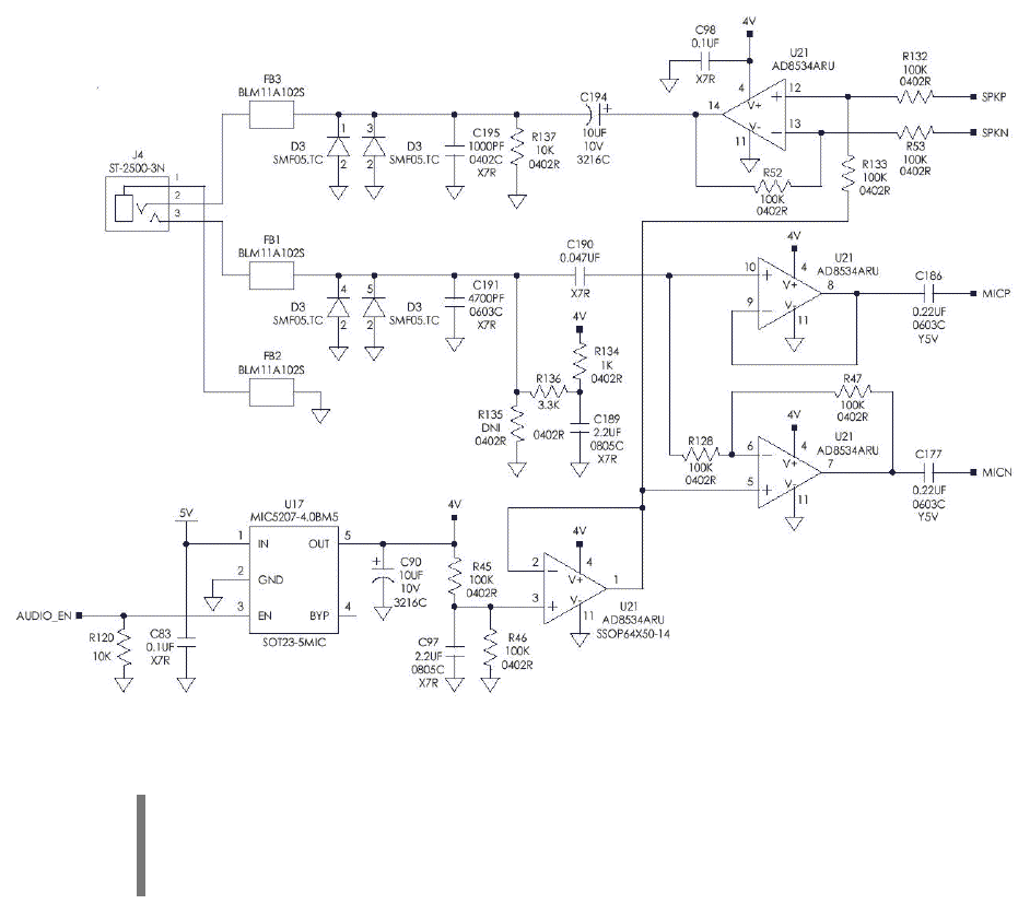
7.4.1 Example Single-Ended Microphone Circuit
Figure 3 shows an example of how to implement a single ended microphone circuit
compatible with the Core Engine.
Figure 2: Single-Ended Microphone Circuit (Example)
NOTE: The FB1, FB2 and FB3 components are ferrite beads to suppress any energy
on to the headset cord. Component D3 is a transient surge suppressor to protect
against ESD.
Core Engine GSM/GPRS Modem Developer Guide Preliminary Draft: 7/6/2001 32
Part Number: 07100026, Revision: 002 Confidential
© 2001 Xircom, Inc., an Intel company All rights reserved.
All trademarks and copyrights are the property of Xircom, Inc., an Intel company
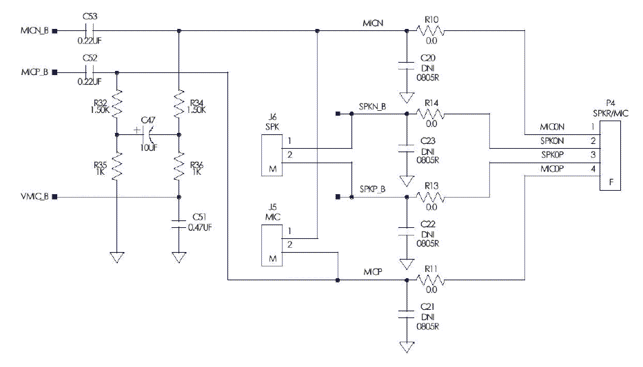
7.4.2 Example Differential Microphone Circuit
Figure 4 shows an example of how to implement a differential microphone circuit
compatible with the Core Engine.
Figure 3: Differential Microphone Circuit (Example)
7.5 Microphone Cable Considerations
The differential circuit design in the Core Engine baseband processor has excellent
common mode voltage rejection for noise signals.
If the microphone is located reasonably close to the Core Engine module, it should be OK
to use unshielded cable. However, this also depends on where the cable is routed. Slight
TDMA framing noises may be noticed if the cable is close to the antenna.
It is recommended that a twisted pair cable be used from the Core Engine microphone
connector to the microphone element. If problems arise, then a shielded cable (i.e.
termination of the shield) may be used.
Core Engine GSM/GPRS Modem Developer Guide Preliminary Draft: 7/6/2001 33
Part Number: 07100026, Revision: 002 Confidential
© 2001 Xircom, Inc., an Intel company All rights reserved.
All trademarks and copyrights are the property of Xircom, Inc., an Intel company
8
8
R
RF
F
A
AN
NT
TE
EN
NN
NA
A
8.1 Antenna Connector
The Core Engine modem includes an on-board RF antenna connector. The modem is
designed to support interchangeable antenna types provided they have impedance of 50
ohms.
The Core Engine on-board RF antenna connector is a MuRata Microminiature SMT
Coaxial Connector (muRata p/n “MM9329-2700”).
8.2 Antenna Selection
The selection of an antenna for use with any radio or radio system, whether integrated of
remote, is a process that cannot be taken to lightly. To simplify the process and identify a
few key performance metrics is difficult to do since antennas are extremely sensitive to
the environment in which they are placed. If the antenna is integrated into a plastic cover
that will be used in a handheld device, then all antenna performance measurements
should be made with the integrated solution held in a hand, or hand simulator. Similar
measurement criteria should be used for units used near the head, on a tabletop, wall,
etc. In this way, the antenna can be tuned for best performance while operating in the
environment that it will be expected to operate in when used by the customer.
As a result, the following criteria assumes that, as a minimum, the antenna is being
measured as it will be used in the final product, i.e. either integrated with the radio or in
free space.
8.3 Antenna Performance Guidelines
8.3.1 Antenna Impedance Match
The antenna impedance within the operating bands of interest should match the
impedance of the radio RF port for maximum power transfer.
Almost universally the antenna port impedance is 50 ohms. The metric used to determine
how well the antenna is matched to 50 ohms is called the return loss or VSWR. These
values can be used to calculate the mismatch loss, which in turn can be used directly as a
loss in the overall system link budget. For a mismatch loss of 1 dB or less, the return loss
must be less than –7 dB (VSWR less than 2.6:1) across all bands of operation. A return
loss of –9.5 dB (VSWR = 2.0:1) results in a mismatch loss of –0.5 dB.
It should be noted that a large impedance mismatch at the antenna port could lead to
more severe losses in radio performance than those calculated here. This is due to the
fact that the radio power amplifier/low noise amplifier and filtering circuits are tuned for
peak performance with a 50 ohm load. Any deviation from this matching impedance will
cause a load line deviation for these devices, which if very large (VSWR > 2:1), can cause
serious degradation to the power output, noise figure, or filter frequency response of the
radio.
Core Engine GSM/GPRS Modem Developer Guide Preliminary Draft: 7/6/2001 34
Part Number: 07100026, Revision: 002 Confidential
© 2001 Xircom, Inc., an Intel company All rights reserved.
All trademarks and copyrights are the property of Xircom, Inc., an Intel company
8.3.2 Antenna Pattern and Gain
The antenna pattern shape should be consistent for all frequencies of operation. The
radiation pattern shape and maximum gain should be consistent with the radio link
performance objectives and the anticipated deployment configurations. This combination
of factors will determine if a directional or omni-directional antenna pattern shape is
desired. In general, for a portable device the antenna pattern shape should be omni-
directional with a peak gain that is less than 2dBi and an average total field gain (vertical
and horizontal polarization combined response) that is -4dBi or greater.
Directional antennas can be used for wall mount applications. These antennas should
have a directional radiation pattern with a peak gain broadside to the antenna. For most
applications, these antennas should have a 10 dB front-to-back ratio as a minimum. The
peak gain will be a function of the system performance requirements and regulatory
allowances.
FCC requirements limit the amount of antenna gain permissible. The combination of
antenna and cable loss (if any) must be selected to maximize path gain within the FCC
requirements (maximum of 3dBi for mobile and 7dBi for fixed applications).
8.3.3 Antenna Beam Width
For mobile applications, the installer should select an omni-directional antenna with good
elevation beam width. With an omni-directional antenna, you trade some gain (azimuth)
for an increased elevation beam width (elevation). Good omni-directional antennas with
2-3dBi gain, and a good elevation beam width are readily available.
Fixed applications could use any type of antenna because there is more flexibility in gain,
but unless the installation site is on the outer fringes, or in a deep fade area, (major
obstructions) gain is the most important thing. Again, you trade gain for beam width
(azimuth and elevation).
The Installer should keep in mind that networks and site environments change. For
example, new cell sites are added to expand existing coverage and/or capacity. With this
growth, new obstructions are added as well, which could change the signal quality for
fixed applications (e.g. a newly constructed building).
Therefore, it is recommended that the installer not install highly directional antennas
attempting to pinpoint the link to a serving base station. Due to the FCC restrictions, the
installer should be able to find a good performing antenna, which provides decent gain,
and good beam width performance.
In order to accomplish “seeing” as much of the network as possible, the installer is
advised to use as broad of a beam width as possible (and reasonable given any particular
installation).
Installation using these guideline, avoid potential problems such as:
! New base station sites, installed closer to site but which cannot be "seen" by
the network.
! Serving cell taken out of service temporarily, but the network lacks the ability
to jump to other cell sites
! Newly constructed obstructions, resulting in a change to the RF
environmental characteristics.
Core Engine GSM/GPRS Modem Developer Guide Preliminary Draft: 7/6/2001 35
Part Number: 07100026, Revision: 002 Confidential
© 2001 Xircom, Inc., an Intel company All rights reserved.
All trademarks and copyrights are the property of Xircom, Inc., an Intel company
8.3.4 Antenna Polarization
Antenna polarization is normally defined as vertical, horizontal, slant left, slant right, or
circular. For portable devices, polarization purity is not required nor desired. Due to the
random positions that a portable device can be used in, and due to the fact that a
significant de-polarization of the predominantly linear polarization of the serving base
station will occur in most user environments, it is important that a portable device have an
antenna that will respond well to all polarizations. This is generally known as “dirty”
polarization and can be described as a polarization ellipse with an axial ratio (ratio of the
maximum to minimum response of the polarization ellipse) of 7 to 9 dB.
8.4 Antenna Location and Network Communication
The antenna location for modem installation is dependent on the individual site conditions.
As a rule, the antenna should be positioned so that a reliable radio connection can be
made with the GSM network. The following guidelines will assist the installer in making
this determination.
! Where the reliability of the signal strength would be in question, one or more base
stations would enhance quality of the signal.
! Where possible, the modem location should be selected so that the antenna has an
unobstructed line of sight to the selected base-station(s)
! The antenna should be located to maximize the signal strength and quality received
from the selected base-station(s).
! It is recommended that the installer obtain GSM Network coverage maps from the
GSM operator indicating that the installation site is in a covered area. It is also
recommended that coverage and signal quality be verified prior to installation, using a
GSM handset.
! If possible, the modem and its associated antenna should be deployed inside an
environmentally controlled protected structure (such as an office building).

Core Engine GSM/GPRS Modem Developer Guide Preliminary Draft: 7/6/2001 36
Part Number: 07100026, Revision: 002 Confidential
© 2001 Xircom, Inc., an Intel company All rights reserved.
All trademarks and copyrights are the property of Xircom, Inc., an Intel company
9
9
P
PR
RO
OV
VI
IS
SI
IO
ON
NI
IN
NG
G
T
TH
HE
E
S
SI
IM
M
The GSM SIM can support optional features or services. Most GSM operators typically
configure the SIM to send/receive voice calls and to receive SMS; however, some may
require an additional tariff to enable the SIM to send SMS. The transmission of data and
fax are also additional services that may require tariffs and additional provisioning. Each
of these services has two separate modes that must be enabled to allow the service:
! Mobile-originated (MO): allows making a service request (such as, making a call or
sending an SMS)
! Mobile-terminated (MT): allows receiving a service request (such as, receiving a
phone call or an SMS)
It is imperative for the Core Engine modem that the SIM be configured for the optional
services that are required for the application.
9.1 GSM Services Supported by the Core Engine modem
The Core Engine modem supports three (3) GSM services (modes of operation) that must
be enabled by the operator:
! Voice calls (MO and MT): requires a telephone number
! SMS (MO and MT): uses the telephone number for Voice
! Circuit-switched data calls (MO and MT): requires a telephone number
The GSM SIM can have multiple telephone numbers: one number for voice calls and SMS
and one number for data calls.
9.2 Selecting the Modes of Operation
When provisioning the SIM for the Core Engine modem, enable the following modes of
operation:
! Voice calls: configure the SIM for both MO and MT service (to send and receive)
! SMS: configure the SIM either for MT alone (to receive) or for both MO and MT (to
send and receive)
! Data: configure the SIM either for MO alone (to send) or for both MO and MT (to send
and receive)
Voice SMS Data Function
MO/MT MT MO Voice calls, receive SMS, make data calls
MO/MT MT/MO MO Voice calls, receive/send SMS, make data calls
MO/MT MT/MO MO/MT Voice calls, receive/send SMS, make/receive data calls
(requires an additional data telephone number)

Core Engine GSM/GPRS Modem Developer Guide Preliminary Draft: 7/6/2001 37
Part Number: 07100026, Revision: 002 Confidential
© 2001 Xircom, Inc., an Intel company All rights reserved.
All trademarks and copyrights are the property of Xircom, Inc., an Intel company
1
10
0
I
IN
NS
ST
TA
AL
LL
LA
AT
TI
IO
ON
N
&
&
I
IN
NI
IT
TI
IA
AL
LI
IZ
ZA
AT
TI
IO
ON
N
10.1 Installation and Verification
10.1.1 Installation
10.1.1.1 Install SIM card.
NOTE: The SIM card is supplied by the service provider, and is not supplied by Xircom.
The Core Engine unit will not operate without a properly coded SIM card installed.
! Disconnect all power to the unit before installing the SIM card.
! Install the SIM card in the SIM card slot (connector J7) on the Core Engine carrier
board.
10.1.1.2 Terminal Connect & Setup
Connect the Terminal to the Primary Serial Port (DB-9) connector (P5 on the carrier
board) using a standard (straight thru) modem cable. The diagnostic terminal can be a
laptop PC, with a serial port connection, running a program such as ProComm or other
communication application.
Set up the diagnostic serial communication to the Core Engine default values:
Baud Rate 9.6 Kbps Stop Bits 1
Data 8 bits Parity No
Duplex Full
Table 9: Core Engine default serial interface values.
10.1.1.3 Connect Power Supply Cable
Install the power supply per manufacturer’s recommended procedures. Plug the power
supply cable plug into the modem power connector (J17 or J18). The connector is keyed
so it can only be installed one way. The connector also has an automatic locking feature
that will engage when the connector pair is fully mated and is easily releasable with finger
pressure.
10.1.1.4 Verify all Terminal Connections
Check that all Core Engine connections have been installed per the instructions in this
manual, and that the power cable (or cord) is secured with no exposed wires.

Core Engine GSM/GPRS Modem Developer Guide Preliminary Draft: 7/6/2001 38
Part Number: 07100026, Revision: 002 Confidential
© 2001 Xircom, Inc., an Intel company All rights reserved.
All trademarks and copyrights are the property of Xircom, Inc., an Intel company
10.1.1.5 Apply Power
10.1.2 Verification
10.1.2.1 Using AT Commands
In the GSM vocabulary, a call from GSM mobile to the PSTN is called a "mobile-
originated call" or "outgoing call." A call from the fixed network to a GSM mobile is called a
"mobile-terminated call" or "incoming call."
In the following examples, “App” refers to the application. The following convention
describes the direction of the data exchange:
! The data exchange from the customer application to the Core Engine modem is
designated as: App > Modem
! The data exchange from the Core Engine modem to the customer application is
designated as: Modem > App
NOTE: With the exception of the +++ command (Online Escape Sequence), all
commands must be preceded by the AT attention code (or command prefix) and
terminated by pressing the <CR> character.
In the following examples, the <CR> and <CR><LF> are intentionally omitted for clarity
and space.
10.1.2.2 Initial Response to the AT Command
After power is applied to the Core Engine, the modem performs a power-up self-test.
When queried with the AT command, the Core Engine modem responds with one of the
following result codes:
! OK signifies that the Core Engine modem is ready, that it correctly interprets the AT
command, and that it can execute the command.
! ERROR signifies that the Core Engine modem does not understand the command or
that the command is invalid.
App > Modem AT
Modem > App OK Command valid: modem is ready
The Core Engine modem must be in Command mode when any command is entered
(with the exception of the online escape sequence +++). Commands entered when the
modem is in Online mode are treated as data, and are transmitted as such to the
receiving modem.
10.1.2.3 Modem Initialization
The following example provides the sample AT commands and responses for the
following initialization tasks:
! Disable character echo
! Set the modem to Verbose mode (to display result codes as words)

Core Engine GSM/GPRS Modem Developer Guide Preliminary Draft: 7/6/2001 39
Part Number: 07100026, Revision: 002 Confidential
© 2001 Xircom, Inc., an Intel company All rights reserved.
All trademarks and copyrights are the property of Xircom, Inc., an Intel company
! Set the DCD to ON
! Monitor the DTR
App > Modem ATE0Q0V1&C1&D0 Initialization string
Modem > App OK Command is valid
App > Modem ATS0=1 Auto answer on 1st ring
Modem > App OK Command is valid
10.1.2.4 SIM PIN Status
The following example provides the AT command and response for querying the PIN
status and entering the SIM PIN number if required.
App > Modem AT+CPIN? Query the SIM PIN status
Modem > App +CPIN: Ready
OK
GSM terminal is not waiting for any password
+CPIN: SIM PIN terminal is waiting for PIN
+CPIN: SIM PUK terminal is waiting for PUK
ERROR SIM is not installed
If the response is +CPIN:Ready, then skip the remainder of this paragraph. If the
response is +CPIN:SIM PIN then proceed with the remainder of this paragraph to enable
the terminal by entering the SIM PIN.
CAUTION: Use care when entering the SIM PIN. If it is entered incorrectly three times
in a row, the GSM terminal will lock and a SIM PUK is required to unlock the SIM.
App > Modem AT+CPIN=”1234” Enter the PIN number
Modem > App OK Command is valid
App > Modem AT+CPIN? Query the SIM PIN status
Modem > App +CPIN: Ready
OK
GSM terminal is not waiting for any password
+CPIN: SIM PIN terminal is waiting PIN
If the response is +CPIN:Ready, then skip the remainder of this paragraph. If the
response is +CPIN:SIM PIN then carefully verify that you have the correct SIM PIN and
repeat the SIM PIN entry.
10.1.2.5 Data Call Setup (modem origination)
The following example provides the AT command and response for setting the Core
Engine modem for 9600 baud, non-transparent mode.

Core Engine GSM/GPRS Modem Developer Guide Preliminary Draft: 7/6/2001 40
Part Number: 07100026, Revision: 002 Confidential
© 2001 Xircom, Inc., an Intel company All rights reserved.
All trademarks and copyrights are the property of Xircom, Inc., an Intel company
App > Modem AT+CBST=7,0,1 9600 baud, non-transparent mode
Modem > App OK Command is valid
10.1.2.6 Modem Status Commands
The following examples provide the AT commands and responses for querying the status
of the unit.
! The following command checks to determine if the Core Engine modem has
successfully registered with the GSM network.
App > Modem AT+CREG? Get the registration status
Modem > App +CREG: 0,1*
OK
Registered with home network
+CREG=0,2 registration in progress
+CREG=0,5 registered as roaming
*First character can be “0” or “1”: “0” for manual response, “1” for auto response.
! The following command queries the strength of the RF coverage. This command
provides information about the RF coverage for the Core Engine modem.
App > Modem AT+CSQ Get the signal strength (for this command, do not
enter “?”)
Modem > App +CSQ: 20,99
OK
Receive signal strength = 20, -74 +/- 1 dBm
RXQUAL =99, unknown
Value RSSI (dBm)
+/- 1 dBm Value RSSI (dBm)
0
<-
11
0
16
-
82
1
-
110
17
-
80
2
-
109
18
-
78
3
-
108
19
-
76
4
-
106
20
-
74
5
-
104
21
-
72
6
-
102
22
-
70
7
-
100
23
-
68
8
-
98
24
-
66
9
-
96
25
-
64
10
-
94
26
-
62

Core Engine GSM/GPRS Modem Developer Guide Preliminary Draft: 7/6/2001 41
Part Number: 07100026, Revision: 002 Confidential
© 2001 Xircom, Inc., an Intel company All rights reserved.
All trademarks and copyrights are the property of Xircom, Inc., an Intel company
11
-
92
27
-
60
12
-
90
28
-
58
13
-
88
29
-
56
14
-
86
30
-
54
15
-
84
31
-
52
Table 10: RSSI vs. Received Signal Power
Value RSSI (dBm)
0
BER
<
0.2%
1
0.2%
<
BER
<
0.4%
2
0.4%
<
BER
<
0.8%
3
0.8%
<
BER
<
1.6%
4
1.6%
<
BER
<
3.2%
5
3.2%
<
BER
<
6.4%
6
6.4%
<
BER
<
12.8%
7
12.8%
<
BER
Table 11: RXQUAL vs. Bit Error Rate
! The following command requests the current Public Land Mobile Network (PLMN).
DeTeMobil is used as an example, the PLMN may be different.
App > Modem AT+COPS? Request current PLMN
Modem > App +COPS:
0,0,”DeTeMobil”
OK
PLMN is DeTeMobil
10.2 SMS Message Verification
10.2.1 Modem Sent SMS (Text)
To be able to send SMS text messages, the Core Engine modem must be initialized with
the proper SMS mode. The following examples provide the AT commands and responses
for initializing the SMS mode.
! The following command initializes the Core Engine modem by setting the text mode
parameters.

Core Engine GSM/GPRS Modem Developer Guide Preliminary Draft: 7/6/2001 42
Part Number: 07100026, Revision: 002 Confidential
© 2001 Xircom, Inc., an Intel company All rights reserved.
All trademarks and copyrights are the property of Xircom, Inc., an Intel company
App > Modem AT+CSMP=17,167,0,0 Set text mode parameters:
# 17: Sets reply pat, user data header,
status report request, validity period
format, reject duplicates and
message type
# 167: Sets validity period
# 0: Higher layer protocol indicator
# 0: Information encode format
Modem > App OK Command is correct
! After initializing the modem with the proper SMS mode, select the proper service
center. The service center is the Public Land Mobile Network (PLMN) to which the
SME telephone number belongs. The following command selects the service center.
Voicestream is used as an example, the users home PLMN may be different.
App > Modem AT+CSCA="+491710760000" Service center initialization:
D1 – Germany
Modem > App OK
! The following command selects TEXT mode for SMS messages.
App > Modem AT+CMGF=1 Set message format to TEXT mode
Modem > App OK Command is correct

Core Engine GSM/GPRS Modem Developer Guide Preliminary Draft: 7/6/2001 43
Part Number: 07100026, Revision: 002 Confidential
© 2001 Xircom, Inc., an Intel company All rights reserved.
All trademarks and copyrights are the property of Xircom, Inc., an Intel company
! The following command sets the indicators for the message.
App > Modem AT+CNMI=1,1,0,0,0 Set the new message indicators
AT+CNMI=<mode>,<mt>,<bm>,<ds>,<bfr>
# <mode>=1, discard unsolicited result
codes indication
# <mt>=1, SMS-DELIVERs are routed using
unsolicited code
# <bm>=0, no CBM indications are routed
to the TE
# <ds>=0, no SMS-STATUS-REPORTs
# are routed
# <bfr>=0, TA buffer of unsolicited result
codes defined within this command is
flushed to the TE
Modem > App OK Successful command
! The following command saves the SMS settings. Once the SMS commands have
been saved, the initialization commands do not need to be sent again until they are
changed.
App > Modem AT+CSAS Save SMS settings
Modem > App OK Successful transmission
! After the Core Engine modem has been initialized, the following commands and
sample responses provide the telephone number and the message to be transmitted.
App > Modem AT+CMGS="12017572673" Send a message to the telephone
number (insert user modem phone
number as the value in parenthesis)
Modem > App > Ready to send message
App > Modem Hello, how are you?^Z Enter the text message. End the
message with Control Z.
Modem > App +CMGS: 1
OK
Successful transmission

Core Engine GSM/GPRS Modem Developer Guide Preliminary Draft: 7/6/2001 44
Part Number: 07100026, Revision: 002 Confidential
© 2001 Xircom, Inc., an Intel company All rights reserved.
All trademarks and copyrights are the property of Xircom, Inc., an Intel company
10.2.2 Modem RECEIVE SMS (Text)
The following example provides the AT command for requesting that the Core Engine
modem list received SMS messages. This string requests that the modem send (over the
RS232 interface) all of the messages that have been received.
App > Modem AT+CMGL=”ALL” Read ALL messages received, including status,
originator, message number and message content
(if messages are present)
Modem > App +CMGL: 1, "REC UNREAD", "12017572673"
Hello, how are you?
OK
10.2.3 SIM Data Provisioning Verification (Optional)
At this time the user has the option of verifying the data communications function from the
users system application to the modem prior to connection to the CPE. To check this
path, have the user’s system application send a data stream to the modem and observe
the data stream on the diagnostic terminal for verification of correct performance.
10.2.4 Match Modem Serial port to CPE
The modem is now ready to be interfaced with the CPE. The serial port settings, data
type, and flow control between the modem and the CPE need to be matched. Reference
Table 9 for the Core Engine modem initialization defaults.
1. Match the bearer type selection (transparent deviation on different sheet or non-
transparent data).
2. Match the flow control.
3. Match the serial interface parameters (baud rate, 8 data bits, 1 stop bit, no parity).
4. Set up the terminal serial interface parameters to match the modem (if modem has
changed).
5. Save parameters to non-volatile memory. (AT&W command, AT+CSAS)
10.2.5 Verify Setup
1. Power down the unit
2. Wait 5 seconds and then re-apply power to verify commands were saved properly
3. Power down again.
10.2.6 Connect Primary Serial Port Cable
Plug the RS232 cable from the CPE into the Primary Serial Port connector (DB-9) on the
Core Engine carrier board. The connectors are keyed so it can only be installed one way.
Core Engine GSM/GPRS Modem Developer Guide Preliminary Draft: 7/6/2001 45
Part Number: 07100026, Revision: 002 Confidential
© 2001 Xircom, Inc., an Intel company All rights reserved.
All trademarks and copyrights are the property of Xircom, Inc., an Intel company
10.3 Final Verification
10.3.1 SMS Verification
Repeat the SMS Message Verification section.

Core Engine GSM/GPRS Modem Developer Guide Preliminary Draft: 7/6/2001 46
Part Number: 07100026, Revision: 002 Confidential
© 2001 Xircom, Inc., an Intel company All rights reserved.
All trademarks and copyrights are the property of Xircom, Inc., an Intel company
1
11
1
D
DE
ET
TA
AI
IL
LE
ED
D
S
SP
PE
EC
CI
IF
FI
IC
CA
AT
TI
IO
ON
NS
S
11.1 Physical Dimensions and Weight
Size (L x W x H) including connectors 53.09 mm x 34.80 mm x 5.66 mm
(2.09” x 1.37” x 0.22”)
Weight 15 g (0.5 oz.)
Table 12: Core Engine Size and Weight
11.2 Operating Power
The Core Engine carrier board requires an input voltage of 3.7 VDC +/- 0.3 VDC. The
input source voltage ripple should be less than 20% of the average supply voltage peak-
to-peak under normal operating conditions.
Core Engine modem Average Current (Amps) Peak Current (Amps)
1 TX, 1 RX TBD TBD Ready Mode
(GSM) 1 RX TBD TBD
1 TX, 4 RX TBD TBD Ready Mode
(GPRS Class 10) 2 TX, 3 RX TBD TBD
Standby Mode N/a TBD N/a
RF Disabled Mode N/a TBD N/a
Sleep Mode N/a TBD N/a
PCS 1900
Dormant Mode N/a < 100uA N/a
Table 13: Core Engine Power Modes & Current Requirements
11.2.1 Transmit Power
Core Engine
modem
Power Class Transmit Power
1900 MHz GSM Power Class 1 1-W conducted power maximum (30 dBm +/- 2 dB),
measured at the antenna port
Table 14: Core Engine Transmitted Output Power
Core Engine GSM/GPRS Modem Developer Guide Preliminary Draft: 7/6/2001 47
Part Number: 07100026, Revision: 002 Confidential
© 2001 Xircom, Inc., an Intel company All rights reserved.
All trademarks and copyrights are the property of Xircom, Inc., an Intel company
11.2.2 Receiver Sensitivity
The receiver sensitivity measured at the antenna port is -106 dB (typical) and -104 dB
(minimum).
11.3 Care and Maintenance
The Core Engine modem should be used in a protected environment. The internal
components of the modem must remain dry and free of moisture. Avoid installations in
extremely cold or hot locations, and avoid extreme temperature changes during use.
There are no external or internal maintenance requirements.

Core Engine GSM/GPRS Modem Developer Guide Preliminary Draft: 7/6/2001 48
Part Number: 07100026, Revision: 002 Confidential
© 2001 Xircom, Inc., an Intel company All rights reserved.
All trademarks and copyrights are the property of Xircom, Inc., an Intel company
1
12
2
E
EN
NV
VI
IR
RO
ON
NM
ME
EN
NT
TA
AL
L
S
SP
PE
EC
CI
IF
FI
IC
CA
AT
TI
IO
ON
NS
S
12.1 Climatic
Internal circuitry provides automatic shutdown control to prevent the unit from operating above
or below the specified operating temperature range.
12.1.1 Climatic: Operational
Operating temperature -20°C to +55°C
NOTE: Upper temperature range can be extended under
certain operating conditions.
Relative humidity 5 - 95%
Solar radiation Not Applicable
Air pressure (altitude) 70 kPa to 106 kPa (-400 m to 3000 m)
12.1.2 Climatic: Storage and Transportation
Duration 24 months
Ambient temperature -40°C to +85°C
Relative humidity 5% to 95%, non condensing (at 40°C)
Thermal shock -50°C to +23°C, +70°C to +23°C; < 5 min
Altitude -400 m to 15,000 m
12.2 Mechanical
12.2.1 Mechanical: Operational
Operational vibration, sinusoidal 3.0 mm disp, 2 to 9 Hz; 1 m/s2, 9 to 350 Hz
Operational vibration, random 0.1 m2/s3, 2 to 200 Hz
12.2.2 Mechanical: Storage and Transportation
Transportation vibration, packaged ASTM D999
Drop, packaged ASTM D775 method A, 10 drops
Shock, un-packaged 150 m/s2, 11 ms, half-sine per IEC 68-2-27

Core Engine GSM/GPRS Modem Developer Guide Preliminary Draft: 7/6/2001 49
Part Number: 07100026, Revision: 002 Confidential
© 2001 Xircom, Inc., an Intel company All rights reserved.
All trademarks and copyrights are the property of Xircom, Inc., an Intel company
Drop, un-packaged 4-inch drop per Bellcore GR-63-CORE
12.2.3 Mechanical: Proposed Standards
Transportation ETSI Standard ETS 300 019-1-2 Class 2.3 Transportation
Operational ETSI Standard ETS 300 019-1-3 Class 3.1 Operational
Storage ETSI Standard ETS 300 019-1-1 Class 1.2 Storage
12.3 Electromagnetic
12.3.1 Electromagnetic Emissions
Radiated spurious FCC part 24 / Part 15 Class \ B
GSM 11.10 Section 12.2
EN 55022 Class B
12.3.2 Electromagnetic Immunity
TBD

Core Engine GSM/GPRS Modem Developer Guide Preliminary Draft: 7/6/2001 50
Part Number: 07100026, Revision: 002 Confidential
© 2001 Xircom, Inc., an Intel company All rights reserved.
All trademarks and copyrights are the property of Xircom, Inc., an Intel company
1
13
3
G
GL
LO
OS
SS
SA
AR
RY
Y
A
AN
ND
D
A
AC
CR
RO
ON
NY
YM
MS
S
App
Application
Refers to the Application which sends or receives
commands/responses from the Core Engine modem
AT Command Set Commands issued by intelligent device to a modem to
perform functions, such as to initiate call, to answer call, or
to transmit data.
CSD
Circuit Switched Data
Data link from a terminal through the network allowing real-
time, duplex connectivity up to 9600 bytes/second.
CE
European Community
Certification
CPE
Customer Premise Equipment
A terminal in fixed location on the customer’s premises.
Dbi Decibels referenced to an isotropic radiator
DCE
Data Communications
Equipment
Data Communications Equipment
DCS
Digital Cellular System
A collection of services and capabilities providing flexibility
of access and mobility through a combination of wireless
and wire-line networks, utilizing the 1800 MHz bandwidth.
DTE
Data Terminal Equipment
Data Terminal Equipment
EFR
Enhanced Full Rate
Voice (vocoder) compression algorithm which offers the
highest quality voice communication.
EIR
Equipment Identity Register
A database used to store International Mobile Equipment
Identity (IMEI) of a locally issued terminal.
EIRP
Equivalent Isotropic Radiated
Power
In a given direction, the gain of a transmitting antenna
multiplied by the net power accepted by the antenna from
the connected transmitter.
ESD
Electrostatic Discharge
Static electricity that can damage electronic equipment.
FTA
Full Type Approval
GSM Full Type Approval

Core Engine GSM/GPRS Modem Developer Guide Preliminary Draft: 7/6/2001 51
Part Number: 07100026, Revision: 002 Confidential
© 2001 Xircom, Inc., an Intel company All rights reserved.
All trademarks and copyrights are the property of Xircom, Inc., an Intel company
FCC
Federal Communications
Commission
US Government body that defines requirements for
emission level of equipment in the United States.
GPRS
General Packet Radio Service
Standard for packet communications utilizing Global
Standard for Mobility (GSM) infrastructure.
GSM
Global System for Mobile
Communications
Standard for digital communications. Allows consistent
communications in various parts of the world despite
variations in RF spectrum allocations. Transferring the SIM
(see below) permits users to roam by changing terminal
equipment.
IMEI
International Mobile Equipment
Identity
A unique number for each GSM Terminal tracked by the
GSM operators in their Equipment Identity Register (EIR)
database.
Ki A secret code used in authentication and encryption by the
terminal.
LED
Light Emitting Diode
Light Emitting Diode
MMS
More Messages to Send
More Messages to Send
MO
Mobile Originated
A voice or data call originated at the mobile terminal.
MT
Mobile Terminated
A voice or data call originated from the network and sent to
the mobile terminal.
Non-Transparent Mode Delivers a constantly low error rate but with a non-
guaranteed throughput or delay. The Non-Transparent
service provides a performance that is closest to using a
modem over a fixed PSTN line.
NRTL
Nationally Recognized Test
Laboratory
OSHA-approved Nationally Recognized Testing Laboratory
OEM Original Equipment Manufacturer
Packet A collection of data transmitted over a digital network in a
burst.
PCS
Personal Communications
Service
A collection of services and capabilities providing flexibility
of access and mobility through a combination of wireless
and wireline networks.
PDU
Protocol Data Unit
Data packet defined by protocol layer of SMS interface.
PLMN Public Land Mobile Network
PSTN Public Switched Telephone Network

Core Engine GSM/GPRS Modem Developer Guide Preliminary Draft: 7/6/2001 52
Part Number: 07100026, Revision: 002 Confidential
© 2001 Xircom, Inc., an Intel company All rights reserved.
All trademarks and copyrights are the property of Xircom, Inc., an Intel company
RF
Radio Frequency
A frequency at which electromagnetic radiation may be
detected and amplified as an electric current at the wave
frequency.
Rx Receive
Short Message An alphanumeric message of up to 160 characters that can
be sent to or from a GSM terminal.
SIM
Subscriber Identification Module
“Smart Card” technology that contains user information and
has four main functions:
# Authentication
# Storage of data
# Assist in encryption process
# Subscriber protection
SMS
Short Message Services
Services provided by GSM network allowing the
transmission and receipt of short messages.
SMSC
Short Message Service Center
Location of SMS store and forward message server.
TBD To Be Determined
Transparent Mode Delivers a service with a variable error rate, with a
guaranteed throughput and delay.
Tx Transmit
Type Approval Rigorous testing required by GSM operators to ensure
terminals operating on network does not degrade
performance, capacity, or functionality of GSM network.
UL
Underwriters Laboratory
Testing agency chartered with ensuring safety of electrical
devices.
USSD Unstructured Supplementary Service Data
V.24 Serial Interface The ITU-T standard defining interchange circuits between
DTE and DCE. V.24 is the ITU-T equivalent of EIA standard
RS-232, with the exception of voltage levels.
Core Engine GSM/GPRS Modem Developer Guide Preliminary Draft: 7/6/2001 53
Part Number: 07100026, Revision: 002 Confidential
© 2001 Xircom, Inc., an Intel company All rights reserved.
All trademarks and copyrights are the property of Xircom, Inc., an Intel company
1
14
4
U
UP
PD
DA
AT
TI
IN
NG
G
T
TH
HE
E
C
CO
OR
RE
E
E
EN
NG
GI
IN
NE
E
F
FI
IR
RM
MW
WA
AR
RE
E
The Core Engine firmware may be downloaded from a host computer to the Core Engine
through the Core Engine primary serial port. The host computer that holds the firmware
update utilities and the new files that are to be downloaded to the Core Engine must be
connected to the Core Engine primary serial port before the Core Engine is powered up.
When the Core Engine is powered up, it will look for a specific signal on the primary port.
If none is detected, then the Core Engine will boot normally. If a special signal is detected
on the primary serial port at the start of the boot sequence, then the Core Engine will stop
the normal boot sequence and instead it will start the firmware update process.
In addition to the firmware image file to be downloaded to the Core Engine, there are a
number of utility programs required in order to perform the download.
14.1 Required Files
To download a new firmware image, the following files are required:
! serload.exe
! flash.hex
! egload.hex
! newstack.hex
14.2 Download Utility
The software utility used to perform the firmware download is called “serload.exe”.
The download utility works with Windows 95, 98, 2000, and NT, and can be run from a
command line prompt within Windows.
The utility accepts several command line parameters, which determine the host serial port
to use as well as the communications speed to use for the download. Information about
the supported command line parameters can be displayed by issuing a command to run
the utility without any command line parameters.
The command line for information is: serload
where:
serload is the download utility program name
Figure 5 shows the display of information on supported command line parameters.
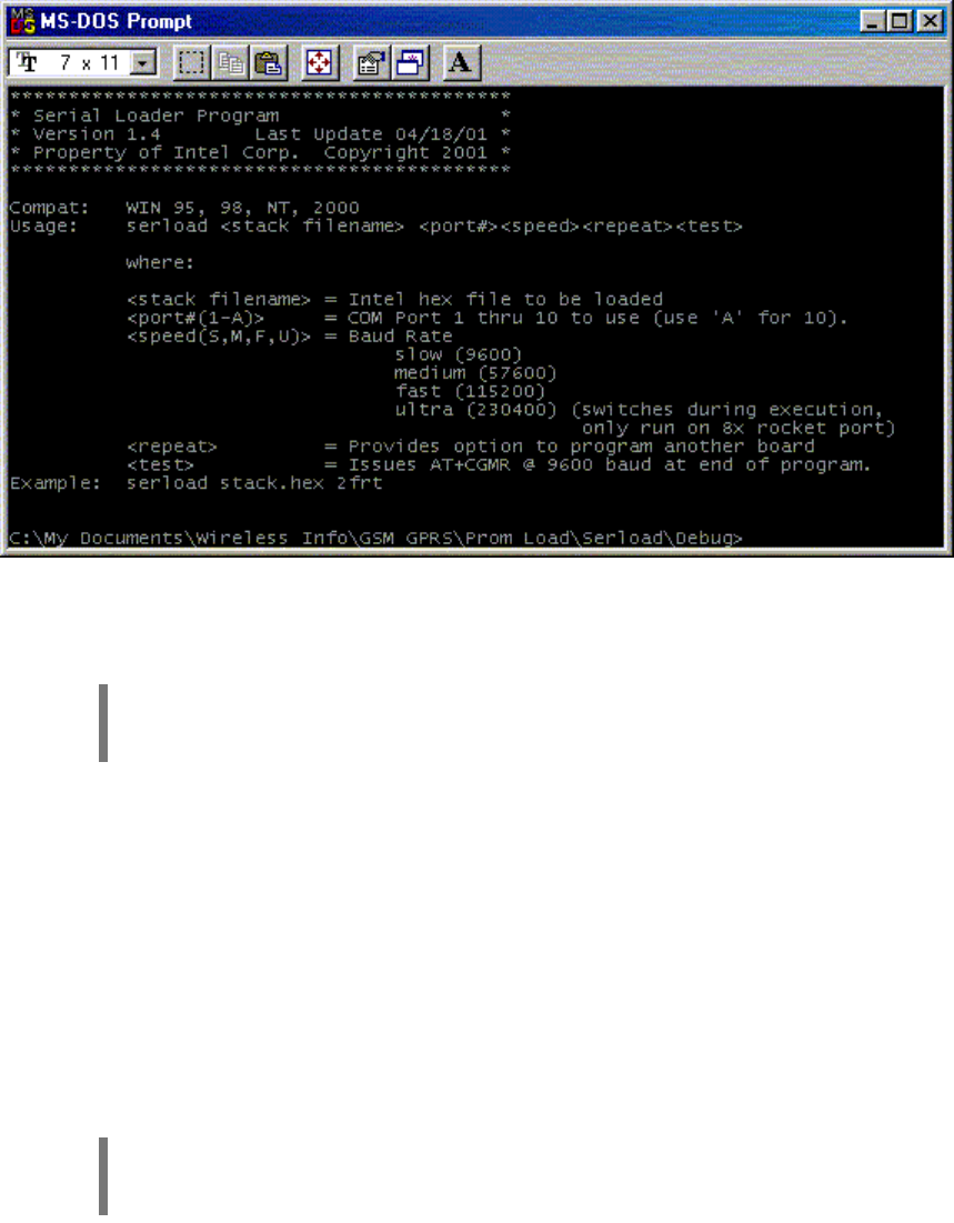
Core Engine GSM/GPRS Modem Developer Guide Preliminary Draft: 7/6/2001 54
Part Number: 07100026, Revision: 002 Confidential
© 2001 Xircom, Inc., an Intel company All rights reserved.
All trademarks and copyrights are the property of Xircom, Inc., an Intel company
Figure 6: Serial Loader Session (Example)
14.3 Download Procedure
IMPORTANT: The Core Engine should be powered off before starting the download
utility.
The command line to perform a download is: serload newstack.hex 1f
where:
serload is the download utility program name
newstack.hex is the firmware image file (Note: the actual filename may vary)
1f is the host computer Com port (e.g. Com1) and speed (f for fast)
The download utility will display several lines of information, then it will pause after
displaying the length of Partition 1 and Partition 2, and a spinning line prompt will appear
indicating the utility is ready to communicate with the Core Engine. Once this prompt
appears the Core Engine can be powered up.
IMPORTANT: Wait for the spinning prompt in the lower left hand corner before
applying power to the Core Engine.
Once power is applied to the Core Engine the utility will display a confirmation that a
communications link has been established, then it will proceed with the download.
The download should take about 4-5 minutes to complete. A successful download will be
indicated by a checksum verification message.
Figure 6 shows an example of a firmware download session.
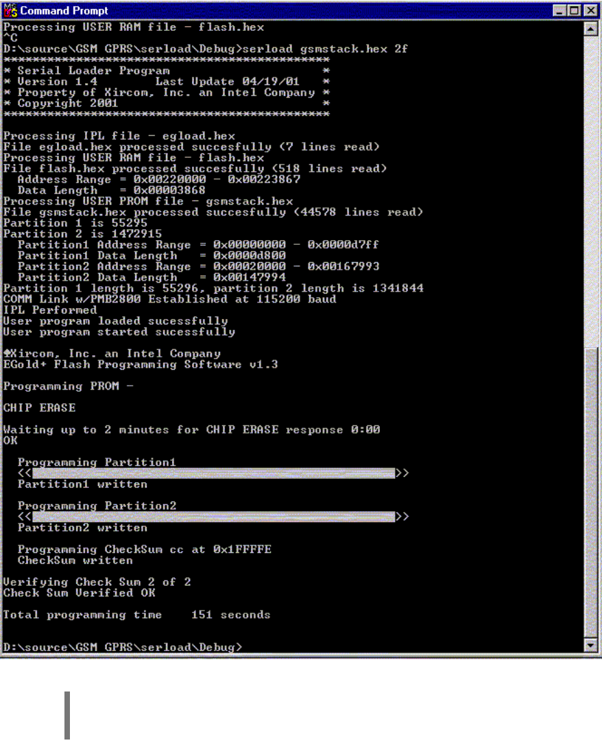
Core Engine GSM/GPRS Modem Developer Guide Preliminary Draft: 7/6/2001 55
Part Number: 07100026, Revision: 002 Confidential
© 2001 Xircom, Inc., an Intel company All rights reserved.
All trademarks and copyrights are the property of Xircom, Inc., an Intel company
Figure 6: Serial Loader Session (Example)
NOTE: After the download is complete you must reset the Core Engine to start the
new firmware.

Core Engine GSM/GPRS Modem Developer Guide Preliminary Draft: 7/6/2001 56
Part Number: 07100026, Revision: 002 Confidential
© 2001 Xircom, Inc., an Intel company All rights reserved.
All trademarks and copyrights are the property of Xircom, Inc., an Intel company
1
15
5
I
IN
NS
ST
TA
AL
LL
LI
IN
NG
G
A
A
R
RE
EM
MO
OT
TE
E
A
AN
NT
TE
EN
NN
NA
A
There are a number of antennas designed for use with the Core Engine modem. If
coverage is poor then the use of a remote antenna may be required. Ideally, the external
antenna is mounted on a rooftop, or on the side of a building where optimal signal
strength can be obtained.
15.1 Antenna Coaxial Cable and Connectors
In most cases RG223 50 ohms or similar small diameter cable can be used. For outdoor
installations, the coaxial cable must be rated for outdoor exposure.
For either fixed or mobile applications, if the antenna has less than a 3 dB gain and a
separation distance of greater than 20 cm (7 7/8 inches) from the body of the antenna,
and any nearby person(s), then the installation will comply with current FCC requirements
addressing human exposure to radio frequency electromagnetic fields.
NOTE: The installer is responsible for assuring that the proper antenna is installed
so that the above limits are not exceeded.
15.2 Outdoor Antenna Grounding
Any outdoor antenna used to transmit or receive RF signals and the antenna connecting
cables must be properly grounded to comply with the National Electrical Code (NEC) -
specifically, but not limited to, articles 250, 800, 810, 820.
Codes require proper grounding of the cables at the point where they enter a building.
Local building codes may also be applicable. For clarification on either local or national
grounding requirements, contact the state or county inspection officials in your location.
15.3 Coaxial Cable Routing
When surveying a site for external antenna installation, verify that there is a suitable path
for the antenna cable from the antenna to the RF antenna connector on the modem. The
coaxial cable must be supported along its path, and protected to assure that damage
does not occur.
NOTE: All cables require routing to be free from any obstacles or any other type of
interference that may cause the cable to be damaged or undergo later damage to
the shielding or cable casing.
Installation of the cables should be in accordance with the manufacturer’s instructions, the
National Electrical Code, applicable building codes, and general industry standards and

Core Engine GSM/GPRS Modem Developer Guide Preliminary Draft: 7/6/2001 57
Part Number: 07100026, Revision: 002 Confidential
© 2001 Xircom, Inc., an Intel company All rights reserved.
All trademarks and copyrights are the property of Xircom, Inc., an Intel company
practices. Emphasis on freedom from obstacles, and the aesthetic guidelines required by
site management should be taken into consideration during the install.
NOTE: Coaxial cables must be professionally installed. Coaxial cables must be
routed and installed in a manner that insures that the jacket, dielectric and outer
shield are not crushed, kinked, cut, scraped or otherwise damaged.
15.4 Coaxial Cable Losses and Lengths
There are some important factors to consider concerning coaxial cable length. The FCC
requires that for mobile applications, the maximum output power can be no more than 2
W (+33 dBm) EIRP, and for fixed applications, no more than 5W (+37dBm). When
using a directional gain antenna and short coaxial cable connections, it is possible to
exceed either FCC requirement. In such cases, additional attenuation must be added into
the path gain. This can be achieved with either in line attenuators, or by adding more
cable length.
To determine the amount of loss needed between the modem and the antenna, the
following formula can be used.
Attenuation needed = g – p
where
g = antenna gain (in dB)
g = maximum path gain allowed by FCC based on the modem maximum output power of
+30 dBm, and where p = 3 dB for mobile applications, or p = 7 dB for fixed applications
To determine the proper minimum cable length the following formula can be used.
L = (g – p) / a
where
L = required minimum cable length
g = antenna gain (in dB; per antenna manufacturers specifications).
p = maximum path gain allowed by FCC based on the modem maximum output power of
+30 dBm, p = 3 dB for mobile applications, or p = 7 dB for fixed applications
a = attenuation per foot of cable (in dB; per cable manufacturers specifications).
As long as installation and operating restrictions previously provided are observed, and
antenna gain is limited to 7 dBi for fixed, or 3 dBi for mobile applications, there is no need
to introduce RF loss between the modem and antenna in order to comply with FCC MPE
limits.
NOTE: Cable loss beyond that required to meet the FCC requirements, with the
given antenna, will decrease the signal strength reaching the modem. This will
negatively impact the ability of the modem to communicate with the network.
For more details and guidelines, please see Table 15 and Table 16 and the following
examples.

Core Engine GSM/GPRS Modem Developer Guide Preliminary Draft: 7/6/2001 58
Part Number: 07100026, Revision: 002 Confidential
© 2001 Xircom, Inc., an Intel company All rights reserved.
All trademarks and copyrights are the property of Xircom, Inc., an Intel company
FIXED APPLICATIONS MINIMUM CABLE LENGTH (feet)
ANTENNA GAIN
(dBi)
REQUIRED PATH
LOSS (dB)
RG 58
(0.33 db/ft)
RG 223
(0.29 db/ft)
RG 8
(0.15 db/ft)
0 0 0 0 0
1 0 0 0 0
2 0 0 0 0
3 0 0 0 0
4 0 0 0 0
5 0 0 0 0
6 0 0 0 0
7 0 0 0 0
8 1 3.0 3.4 6.7
9 2 6.0 6.9 13.3
10 3 9.0 10.3 20.0
Table 15: Cable Loss & Length - Fixed Applications
MOBILE APPLICATIONS MINIMUM CABLE LENGTH (feet)
ANTENNA GAIN
(dBi)
REQUIRED PATH
LOSS (dB)
RG 58
(0.33 db/ft)
RG 223
(0.29 db/ft)
RG 8
(0.15 db/ft)
0 0 0 0 0
1 0 0 0 0
2 0 0 0 0
3 0 0 0 0
4 1 3.0 3.4 6.7
5 2 6.0 6.9 13.3
6 3 9.0 10.3 20.0
7*
8*
9*
10*
* = not recommended
Table 16: Cable Loss & Length - Mobile Applications

Core Engine GSM/GPRS Modem Developer Guide Preliminary Draft: 7/6/2001 59
Part Number: 07100026, Revision: 002 Confidential
© 2001 Xircom, Inc., an Intel company All rights reserved.
All trademarks and copyrights are the property of Xircom, Inc., an Intel company
15.5 Formula Examples
15.5.1 Example 1:
The installer has a nominal 7dB gain antenna, is using RG-223 cable, and is using the
modem in a fixed application.
G = 7 dB
p = 7 dB
a = 0.29 dB/ft
then Attenuation needed = 7 – 7 = 0 dB
and L = (7 – 7) / 0.29 = 0 ft
In this example, the length of cable the installer must use does not matter because he
does not need any loss in the line to meet the FCC requirements.
15.5.2 Example 2:
The installer has a nominal 7 dB gain antenna, is using RG-223 cable, and is using the
modem in a mobile application.
G = 7 dB
p = 3 dB
a = 0.29 dB/ft
then Attenuation needed = 7 – 3 = 4 dB
and L = (7 – 3) / 0.29 = 13.8 ft
In this example, the installer must use at least 13.8 feet of cable or use a 4 dB “in line
attenuator”, or a combination of the two.
15.5.3 Example 3:
The installer has a 10 dB nominal gain antenna, using RG-223 cable, and the modem is in
a fixed application.
G = 10 dB
P = 7 dB
a = 0.29 dB/ft
then Attenuation needed = 10 – 7 = 3 dB
and L = (10 – 7) / 0.29 = 10.3 ft
In this example, the installer must use at least 10.3 feet of cable, or use a 3 dB in line
attenuator, or a combination of the two.
NOTE: The installer is responsible for assuring that the proper antenna, cable
length, and / or attenuation, is installed correctly, so that the limits of FCC §15.203
are not exceeded.