Xirgo Technologies XT1000 Wireless Zigbee Sensor User Manual user guide
Xirgo Technologies Inc. Wireless Zigbee Sensor user guide
user guide
1
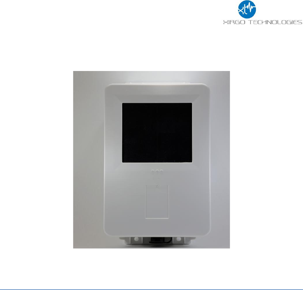
XT-1010 User Guide
Model: XT-1010
FCC ID: GKM-XT1000
IC: 10281A-XT1000
Version 1.1

2
Table of Contents
Document Change History .......................................................................................... 3
1. Introduction ........................................................................................................... 4
1.1 Feature Matrix................................................................................................................................................................................. 4
2. Hardware Description ............................................................................................. 5
2.1 Hardware Specifications ............................................................................................................................................................. 6
2.2 Cable Harness Description......................................................................................................................................................... 6
2.3 LED Description.............................................................................................................................................................................. 7
3. Device Mounting Options: ...................................................................................... 7
3.1 Screw Mounting.............................................................................................................................................................................. 7
3.2 Magnetic Mounting........................................................................................................................................................................ 8
3.3 VHB Tape Mounting...................................................................................................................................................................... 8
4. Quick Start Guide.................................................................................................... 9
4.1 Device Installation......................................................................................................................................................................... 9
4.2 Pairing the XT1010Z and the XT4860G5 ...........................................................................................................................10
4.3 Unpairing Devices........................................................................................................................................................................10

3
Document Change History
Revision
Date
Author
Changes
1.0
8/28/2014
Johnny Chen
Document Creation
1.1
9/2/2014
Johnny Chen
Revision Based on Nader’s Feedback
4
1. Introduction
The XT-1010 is a wireless ZigBee sensor that pairs with the XT-4860G5 generally known as the Base
Unit to provide inclination data based on a 3-axis digital accelerometer readout with an accuracy of
±1 degree. Additional general purpose digital IO sensors can also be queried and transmitted to the
XT-4860G5. The XT-1010 leverages a high efficiency solar energy harvesting platform to support long
term, remote deployments without the burden of frequent battery replacement. This installation
guide describes the physical hardware, associated parts, mounting options, and a quick start-up
procedure.
1.1 Feature Matrix
Feature Description
XT-1010
High Efficiency Solar Panel
6600mAh Rechargeable Li-Ion Battery
Diagnostic LEDs
Optional Digital IO Sensors and 1-Wire Serial Bus
ZigBee pairing with XT-4860G5
Inclinometer Data based on 3-axis Dig Accel. with 1 deg. accuracy
Over-the-air FW upgrade via XT-4860G5
5
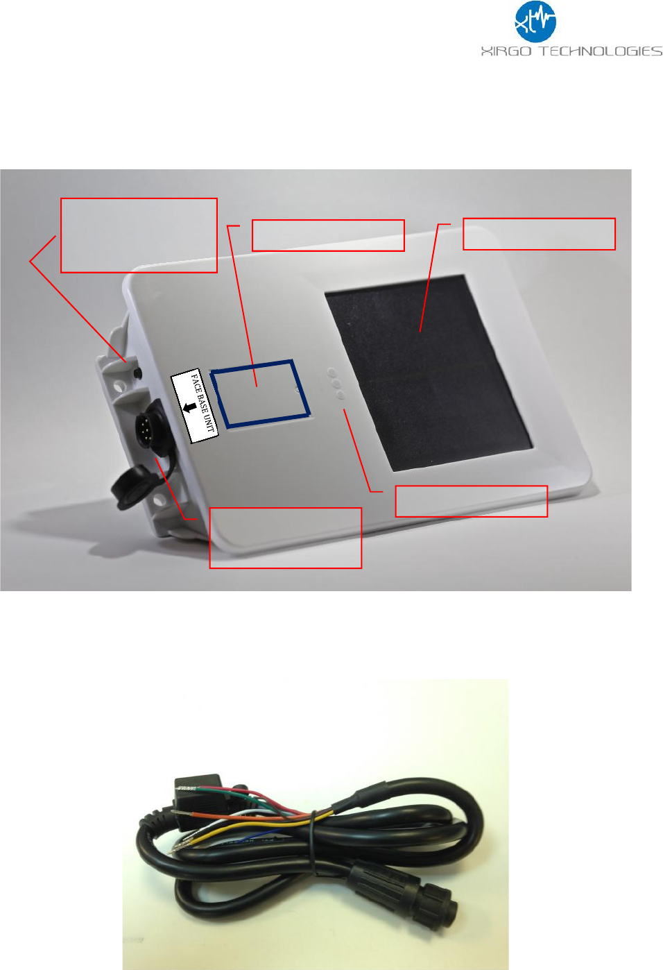
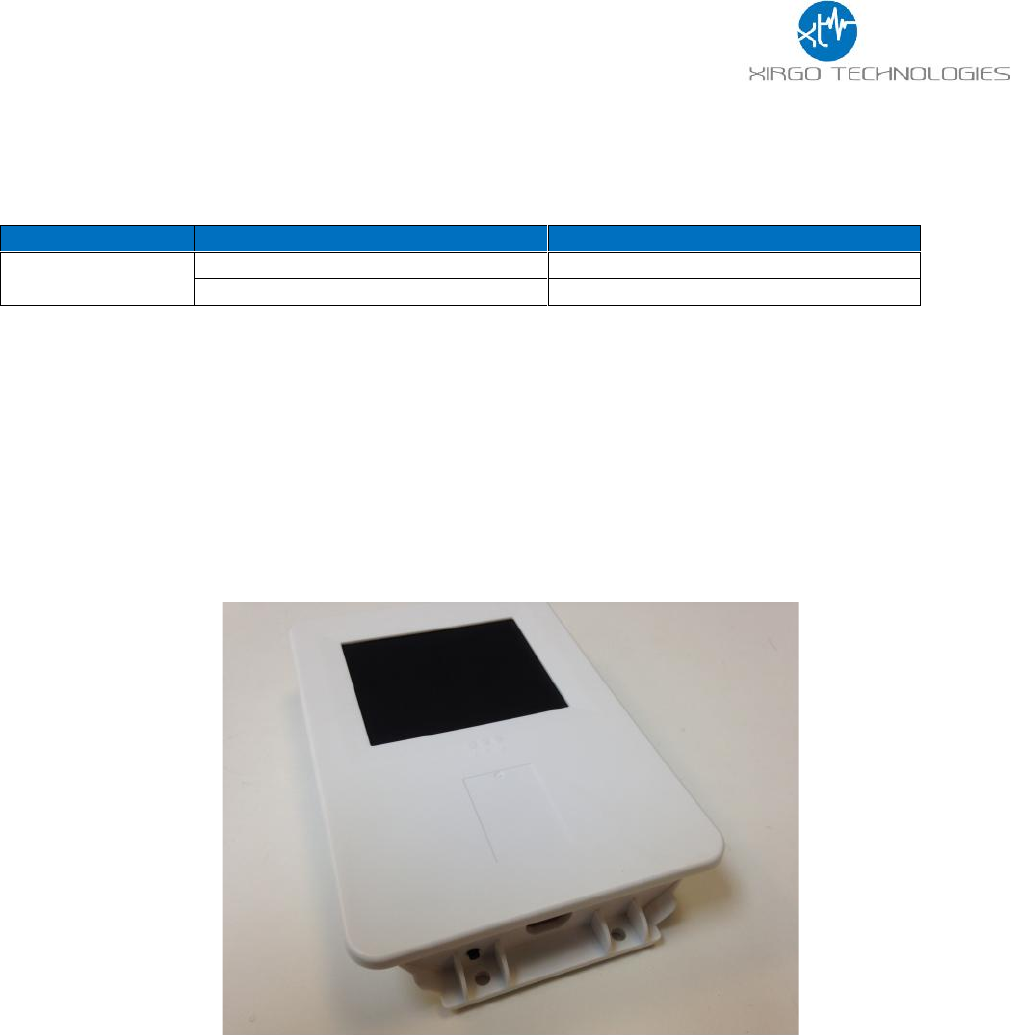
2. Hardware Description
Below is a depiction of key interfaces of the XT-1010:
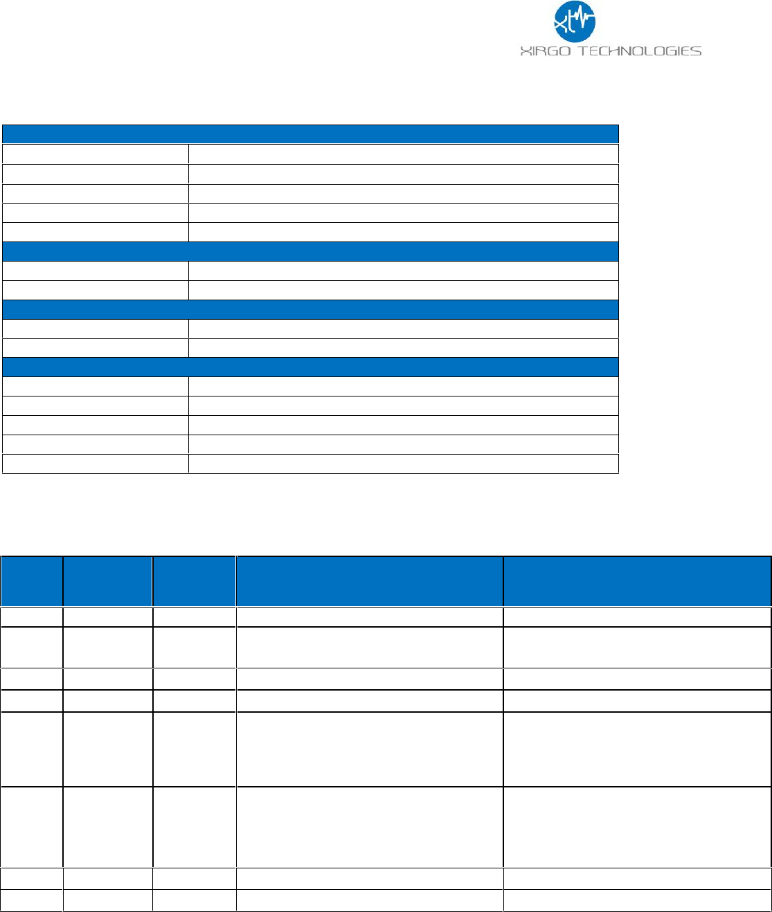
An optional Cable Harness that interfaces with the unit is shown below. The Cable provides
external power, when available, as well as interface to the IO HW options
Solar Panel
LED Indicators
Device Label
ZigBee Pairing
Button
8-Pin Bayonet
Connector
6
2.1 Hardware Specifications
ZigBee Specification
Technology
ZigBee IEEE 802.15.4 DSSS modem
Frequency Band
2405-2483.5MHz
Antenna gain
0.5 dBi (peak again), -0.5 dBi (Average gain)
Transmit power
12dBm/MHz
Data Rate
250 kbps
Power Requirements
D.C. Power (if Avail.)
8-24V, 12 V nominal
Battery
Internal 6600mAh rechargeable Li-Ion
Physical Connection
Interface Connector
8-pin Bayonet type
Programming
Serial (UART Logic Level)
Mechanical
Case Material
ABS plastic with weather-proofing for outdoor use
Dimension
7.6” X 4.9” X 1.4”
Weight
18 oz.
Operating Temperature
-30°C to +70°C
Protection Rating
IP67
2.2 Cable Harness Description
Pin #
Wire
Color
Pin Name
Functional Description
Port Characteristic
1
White
IN1
Ignition Sense
8v to 24v, Internally pulled low
2
Yellow
IN2
Input port
2.4 to 24V, < 0.2 V
Note: Internally pulled high
3
Black
Ground
Ground
4
Green
Out
Output Port (Defaulted open circuit)
5
Blue
UART-Rx
External battery negative terminal
3.3V Logic Interface
Com Port Settings:
Baud rate: 115200 bps; Flow control:
None; 8N1
6
Brown
UART-Tx
3.3V Logic Interface
Com Port Settings:
Baud rate: 115200 bps; Flow control:
None;8N1
7
Red
VBATT
Main battery voltage, DC
8-24 V, 12V Nom.
8
Orange
ADC
Analog Input
8-24 V
7
2.3 LED Description
3. Device Mounting Options:
3.1 Screw Mounting
The XT-1010 can be mounted via 4 mounting screw, 2 per side as depicted below.
LED
Description
Status
GPS (Green)
Pairing Successful
Solid for 30 Seconds then OFF
Stand-by for Pairing
Blinking Steadily
8
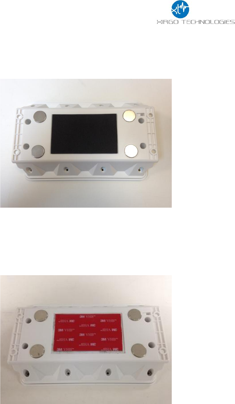
3.2 Magnetic Mounting
The XT-1010 can also be provided with 4 pre-installed (or kitted separately) magnets as depicted
below.
3.3 VHB Tape Mounting
For semi-permanent mounting option, the device can be mounted with 3M VHB tape as shown
below.
9
4. Quick Start Guide
4.1 Device Installation
The XT1010 (Sensor unit) pairs with the XT-4860G5 (Base unit) and provides inclinometer data
based on the on-board 3-axis digital accelerometer output which in turn is transmitted to end
user Server over the cellular network. The proper installation of the unit is critical to acquiring
accurate inclinometer data. An application note entitled “Installing and Pairing the XT-4860 and
XT-1010 for Wireless Inclinometer Functionality” contains detailed instructions for installing and
pairing the two devices. This quick start guide will give you basic steps for installation and
pairing of the two devices. Refer to the application note for any additional detail and instructions.
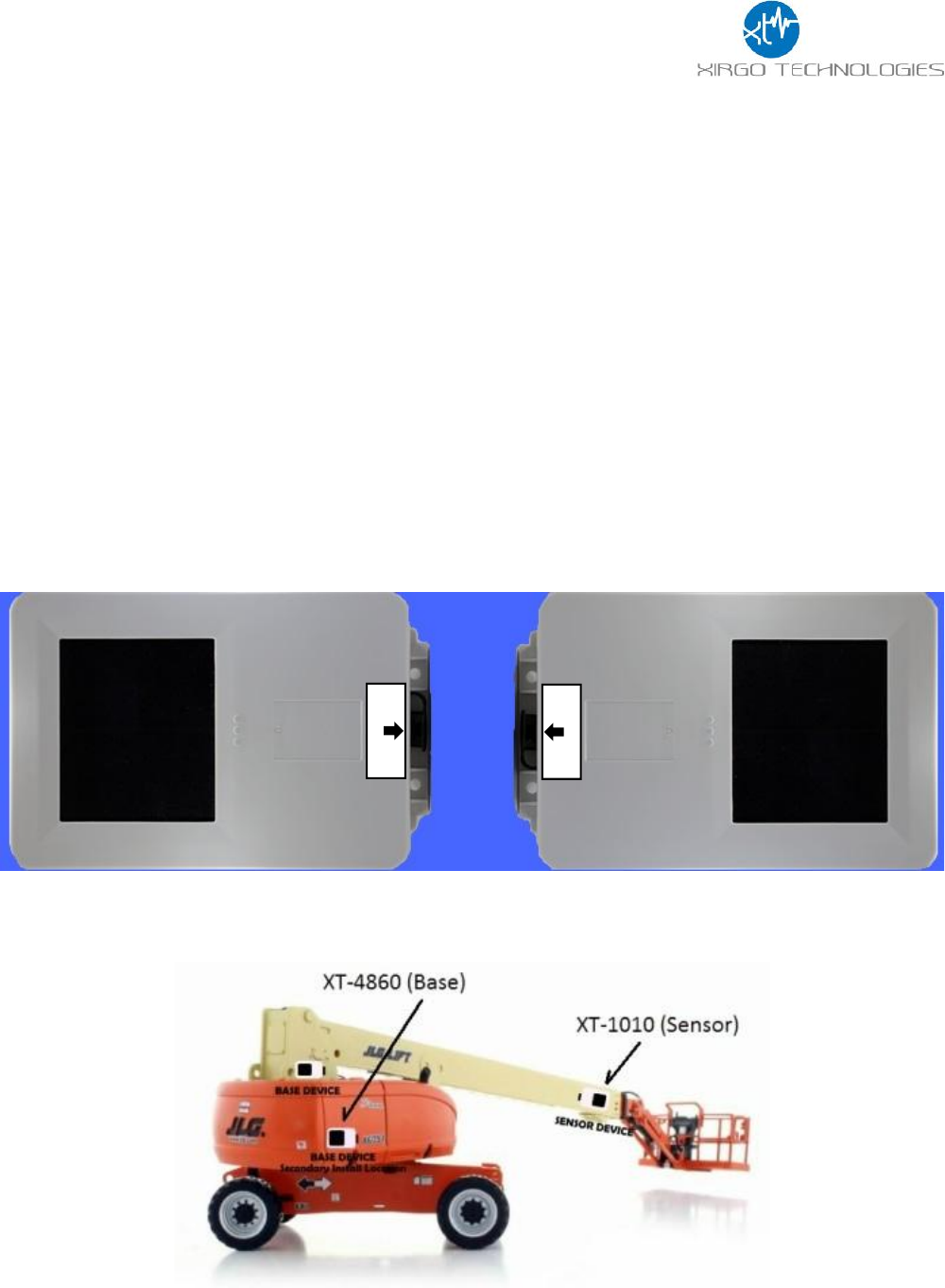
When installing the device, make sure the Base unit (XT-4860G5) faces the Sensor unit (XT-1010)
Each Unit has a label near the 8-pin Connector to show the direction of device installation. The
Base and the Sensor must be on the same plane and facing each other for optimal performance.
The picture below illustrates the ideal orientation of the two devices
As an example, below depicts possible mounting positions of the two Units for a man-lift
application.
FACE BASE UNIT
FACE SENSOR
10
4.2 Pairing the XT1010Z and the XT4860G5
With both Base and Sensor units properly oriented, the pairing process of the two devices can
begin. Note that only one Sensor unit can be paired with one Base unit. During the pairing process,
the devices are calibrated and normalized relative to each other. Once the calibration is complete,
the Devices must not be moved or repositioned.
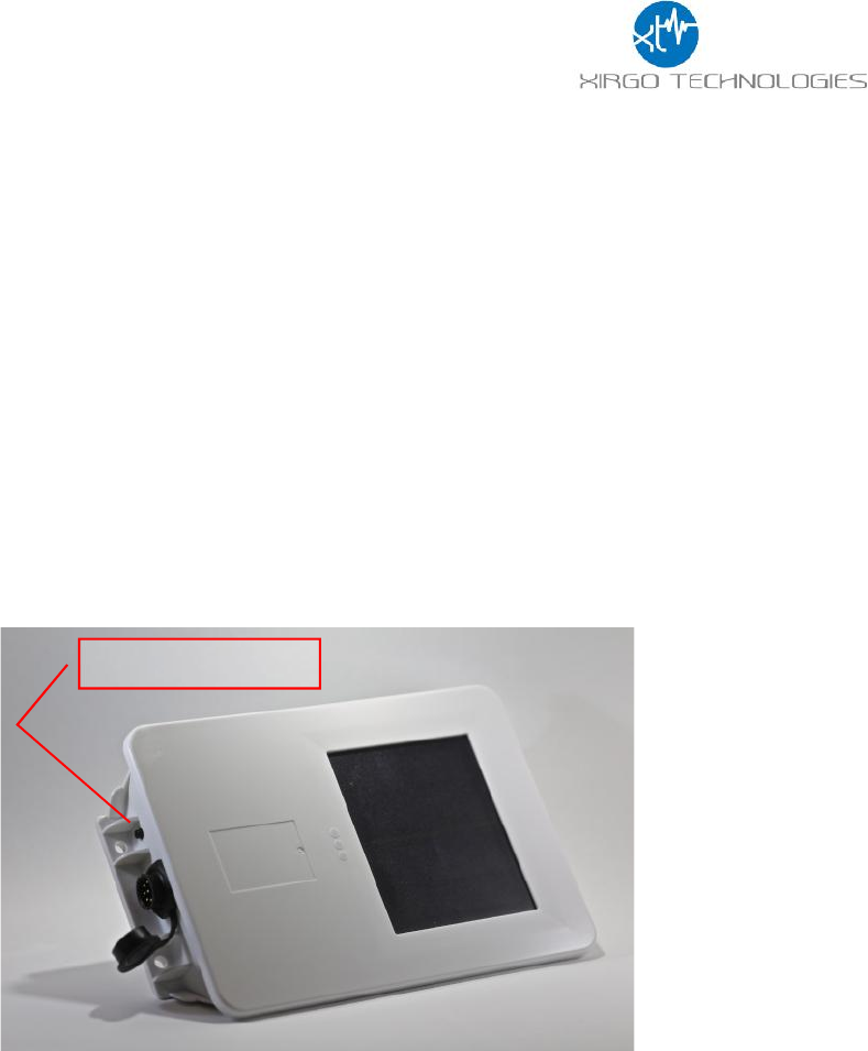
To begin the pairing process, press the black button located near the circular connector on the
side of the Base unit for 5 seconds. You should see the amber LED light (marked with “Z”) flashing
4 times per second. This LED pattern signifies that the Base unit is searching for the Sensor unit
that it is meant to pair with. There is a 60-second window for the pairing process to complete. If
the pairing process was not successful within 60 seconds, then the unit will return to its
configured normal state and the process needs to be repeated if pairing is still needed. At any
time during pairing, the process can be stopped or reset by pressing and holding the button on
either device for 15 seconds, then releasing, or by simply waiting for a timeout.
During the Base unit 60-second pairing time, press and hold the pairing button on the Sensor unit
for 5 seconds. The green LED (marked with a “C”) will flash 4 times per second as well. A typical
pairing process takes about 3 to 5 seconds after pressing the pairing buttons of both Units. After
successful pairing, the Base unit’s orange LED will turn off and the Sensor unit’s green LED will
turn solid for 30 seconds, then it will turn off. After the pairing process, the Sensor unit will
automatically send inclinometer data to the base unit at a rate of 1 sample per 5 seconds.
4.3 Un-pairing Devices
To un-pair a set of paired XT-4860 and XT-1010 devices, press and hold the button on the XT-
4860 device for 15 seconds, then release. That device will attempt to notify its XT-1010 pair of
the pairing reset. There is no LED feedback for a pairing reset. The pairing reset can be performed
individually on an XT-4860 or XT-1010 device if the paired device is no longer present.
Pairing Button

11
FCC/IC:
REGULATORY COMPLIANCE INFORMATION
This equipment with FCC-ID: GKM-XT1000 and IC: 10281A-XT-1000, Model: XT-1010
is subject to the Federal Communications Commission (FCC) and Industry Canada (IC) rules.
NOTICE:
Changes or modifications not expressly approved by the party responsible for compliance could void the user's
authority to operate the equipment.
This device complies with Part 15 of the FCC Rules and with license exempt Radio Standard Specifications of
Industry Canada.
Operation is subject to the following two conditions:
(1) this device may not cause harmful interference, and
(2) this device must accept any interference received, including interference that may cause undesired
operation.
Les changements ou modifications non expressément approuvés par la partie responsable de la conformité
pourraient annuler l'autorité de l'utilisateur à utiliser l'équipement.
Le présent appareil est conforme aux CNR d'Industrie Canada applicables aux appareils radio exempts de
licence. L'exploitation est autorisée aux deux conditions suivantes :
(1) l'appareil ne doit pas produire de brouillage, et
(2) l'utilisateur de l'appareil doit accepter tout brouillage radioélectrique subi, même si le brouillage est
susceptible d'en compromettre le onctionnemen
Radio frequency radiation exposure Information:
This equipment complies with FCC radiation exposure limits set forth for an uncontrolled
environment. This equipment should be installed and operated with minimum distance of 20 cm
between the radiator and your body. This transmitter must not be co-located or operating in
conjunction with any other antenna or transmitter.