YDI Wireless LUC2400E Rooftop Fixed Direct Sequence Transmission System User Manual Cover
YDI Wireless Rooftop Fixed Direct Sequence Transmission System Cover
Contents
- 1. Lucent Manual
- 2. Users and Operators Manual
- 3. users manual
Users and Operators Manual
Model AMP2440
REMOTE BI-DIRECTIONAL POWER
AMPLIFIERS FOR 2.4 GHz
Installation and
Operation Manual
Version 2.0 May 2000
MODEL AMP2440
POLE MOUNTED BI-DIRECTIONAL
POWER AMPLIFIERS FOR 2.4 GHz
Installation and
Operation Manual
Ver 2.2 Dec 2000
Young Design Inc. 146B Hillwood Ave. Falls Church, VA 22046
Tel: (703) 237-9090 Fax: (703) 237-9092
http://www.ydi.com
;our One Shop For
Complete High-Speed Wireless Internet
Systems!!!
www.ydi.com
or
Contact Our Sales Department
Toll Free at:
888-297-9090
703-237-9090
or call

Limited Warranty
Young Design, Inc. (YDI) warrants that your device is free of defects in material and
workmanship for a period of one year after initial purchase. YDI will, in this period of time,
repair or replace, any YDI product returned to the factory, freight prepaid.
The YDI warranty covers repairs or replacement (at YDI’s option) of the product only. YDI is
not responsible for the cost of removal, reinstallation, or shipping to the place of repair. YDI
does not extend or modify its warranty period as a result of repair or replacement.
YDI reserves the right to void a warranty and/or make reasonable charges for the repair of a
unit if the warranty seal is broken or the unit displays evidence of misuse, abuse, or
tampering.
YDI is not responsible for damage to any other equipment or property, or any other
consequential or incidental damages of any kind, whether based on contract, negligence, or
strict liability. Maximum liability shall not in any case exceed the purchase price of the unit.
Warranties give you (the buyer) specific legal rights. You may also have other rights that
vary from state to state. This warranty is only extended to purchases made in the United
States of America or its possessions.
Warranty Notice
The AMP2440 warranty is null and void if any of the following occurs:
1. The amplifier is opened
2. The antenna connections are not properly waterproofed
3. The amplifier is operated with no antenna attached
4. Improper connectors are used
5. The amplifier is mounted outdoors with the connectors facing any direction except
downwards
This device complies with part 15 of the FCC rules. Operation is subject to the
following two conditions: (1) This device may not cause harmful interference, and
(2) this device must accept any interference received, including interference that
may cause undesired operation.
© 2000 Young Design, Inc. All Rights Reserved. No part or parts of this document may be
reproduced, translated, stored in any electronic retrieval system, or transmitted, in any form
or by any means, electronic, mechanical, photocopying, recording, or otherwise, without the
prior written permission of Young Design, Inc.
To see a complete line of our High Speed
Wireless Data products, visit our web site at:
www.ydi.com
or call our Sales Office at:
1-888-297-9090

TABLE OF CONTENTS
1. DESCRIPTION............................................................................................................1
2. AMPLIFIER FEATURES............................................................................................1
2.1 GENERAL SPECIFICATIONS...............................................................................2
3. AMPLIFIER KIT..........................................................................................................3
4. INSTALLATION AND CABLING INSTRUCTIONS...........................................3
5. AMPLIFIER CONNECTIONS AND INDICATORS.............................................5
6. DC POWER INJECTOR OPERATION..................................................................5
7. DC POWER INJECTOR CONNECTIONS AND INDICATORS.......................6
8. POWER SUPPLY........................................................................................................6
9. OPERATION................................................................................................................7
TABLE A - CONVERSIONS FROM DBM TO WATTS...........................................8
TABLE B - TYPICAL CABLE ATTENUATION VALUES........................................8
TABLE C - TYPICAL AMPLIFIER INSTALLATION DETAILS.............................9
APPENDIX A: CALCULATING POWER..................................................................10
APPENDIX B: FCC PART 15 CERTIFIED SYSTEMS............................................11
Professional Installation Required
The amplifier and antennas used must be professionally installed by experienced antenna
installation professionals who are familiar with RF issues (such as gains and losses) as well
as local building and safety codes. Failure to do so will void the product warranty and may
expose the end user to excessive Radio Frequency hazard. Regulations regarding maximum
antenna gains, amplifier power gain, and maximum permissible exposure vary from country to
country. It is the responsibility of the end user to operate within the limits of these regulations
and to ensure that the professional installers who install this device are aware of these
regulations. All antennas are intended to be installed outdoors.
Page 15
NOTES:
1. Description
The AMP2440 is a bi-directional amplifier designed for extending the range of 2.4 GHz
wireless radio modems, Wireless LAN cards, Access Points and wireless bridges. The
units provide transmit power amplification as well as receive signal gain. The amplifier is
installed right at the antenna’s feed point, providing maximum effectiveness of transmit
power. This has the effect of compensating for signal loss in the transmitter cable to the
antenna. Likewise, the Low Noise Amplifier (LNA) in the AMP2440 boosts the receive
signal right at the antenna prior to experiencing the loss in the transmission cable to the
radio. This gain completely overcomes the losses in the transmission cable between the
amplifier and the radio. This results in the lowest possible system Noise Figure. In fact,
use of the amp will actually increase the receiver sensitivity by a few dB! The ultimate
result is the best receiver sensitivity and maximum possible range for whatever antenna
is used.
The amplifier box is weatherproof and can be bolted to the antenna mast or tower leg
using the U-bolt included. When properly installed, the connectors face down so that
gravity will drain all water away from the amplifier enclosure. This will prevent water
from settling on the face of the unit. The LEDs will also be facing downward so that they
can be checked for operation from the bottom of the mast or tower.
DC Power to the amplifier is supplied through the transmission cable that carries the RF
(Radio Frequency) signal. This DC voltage is put on the coax cable using the DC Power
Injector included in the amplifier kit. Both the amplifier and the DC Injector also contain
their own integral lightning protection as well as DC surge protection. No external
antenna lightning protection on the coax cable is required. (The DC Injector has a
grounding stud to facilitate an easy connection to a good earth ground.) It also has
mounting flanges to facilitate permanent installation to a bulkhead or wall. If mounted to a
grounded metal plate, then no extra wiring needs to be attached to the grounding stud.
The amplifier box will provide maximum lightning protection when it is bolted to a grounded
mast or tower. No extra ground straps need to be connected to the amplifier case.
2. Amplifier Features:
•Transmit input levels from 3mW to 100mW
•14 dB transmitter power gain (Standard amp)
•16 dB receive gain
•RX preamp noise figure better then 4 dB (typical)
•Weatherproof Cast Aluminum Case that is mast mountable
•DC Power for the amp carried up through the transmission cable
•Power and Transmit LEDs on both the amp and the DC power injector
•Built-in Lightning Protection
•DC Surge Protection
•Heavy Duty N-type Connectors
•One Year Warranty
•Made in the U.S.A.
Page 1 Page 14
NOTES:
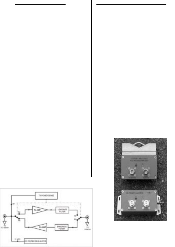
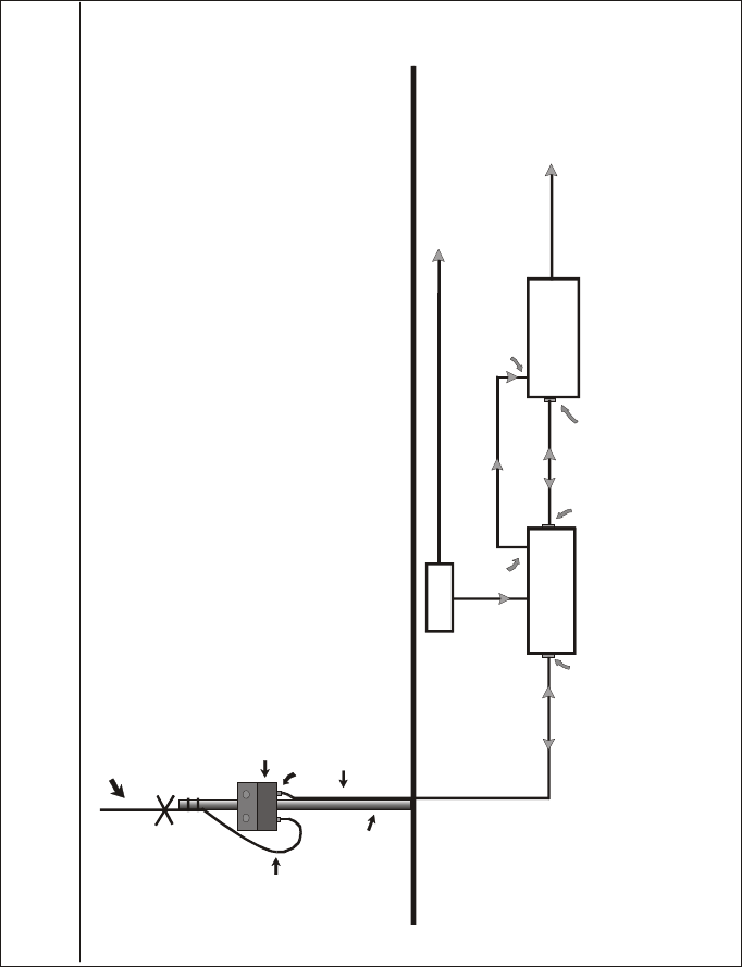
Model 2440 Functional Block Diagram
Receiver Low Noise Amplifier (LNA)
Receive Gain:
Freq Response:
Noise Figure:
16 dB nominal
+/-1 dB over operating range
4 dB typical
Operating Range:
Operating Mode:
Connectors:
Indicators:
Lightning
Protection:
DC Surge
Protection:
2400-2483 MHz
Bi-directional, half-duplex. Senses RF
carrier from transmitter and
automatically switches from receive to
transmit mode.
N-female
TX and RX LEDs on both the amplifier
and the DC bias injector
Direct DC ground at antenna connector.
DC injector serves as lightning arrestor
if properly grounded.
600 Watt TVS at 12 VDC input from
transmis
2.1 General Specifications
Transmitter Amplifier
Transmit Gain:
Freq Response:
Transmit Output
Power:
Duty Cycle:
Transmit Input
Power to Amp:
14 dB nominal for standard amp
(Other versions may have different gains)
+/-1 dB over operating range
250 mW nominal
Up to 640 mW for FHSS radios
Up to 400 mW for DSSS radios
50% Maximum
3mW minimum (+5dBm),
100mW (20 dBm) maximum
(Special versions are available with higher
input power.)
Mechanical, Power and Environmental
Operating
Temperature:
Power:
Dimensions:
Mounting Bracket
for amplifier:
Kit Weight:
-20°C to +60°C
105-240 VAC if using the power
supply provided with the amp kit
or
11 – 14 VDC @ 900 ma peak,
400 ma avg. with an alternate
power source
Amplifier:
4.5” x 2.6” x 1.2 ”
DC Power injector:
5.4” X 2.4” X 1.3 ”
Accommodates pole/mast
diameters
from 3/4” to 3”
Approx. 1.5 lb. with U-bolts
View showing the DC Injector and the
pole mounted outdoor amplifier
attached to its mounting bracket.
Page 2
NOTES:
Page 13
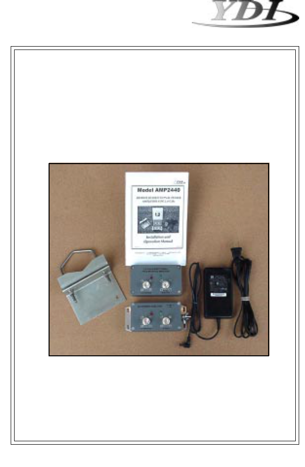
3. Amplifier Kit
Each Amplifier Kit Includes:
• Bi-directional remote mounted amplifier
• DC Power Injector
• 12 VDC, 110/220 VAC Power Supply
• Stainless Steel U-Bolts and mounting
bracket for amp
• Installation Manual
Close up of the bracket and mounting
hardware attached to the amplifier.
The following options are also available and must be ordered separately:
DC power cable with 2.1mm plug to flying lead 3 feet long. Used when the
customer provides their own 12 VDC power for the DC injector or amp.
Option to add second power jack on DC injector to enable one 12 VDC PS
that comes with the amp to power both the Injector and the radio or AP.
(Requires a DC jumper cable. See below).
DC jumper cable that connects a radio modem or Access Point to the
second DC power jack on the DC injector box. Radio devices must have a
2.1 mm ID power jack and operate on 12VDC.
Same as above except used for radios and Access Points that have a 2.5
mm ID barrel jack on them.
4. Installation and Cabling Instructions
FCC Notice
To comply with FCC part 15 rules, the proper version of the amp must only be used in systems
that have been FCC certified. The system must also be professionally installed to ensure
compliance with the Part 15 certification. It is the resposibility of the professional installer to
ensure that certified systems be deployed in the United States (or where FCC rules apply).
The use of the amplifier in any other combination (such as co-located antennas transmitting
the same information) is expressly forbidden in accordance with FCC rules CFR47 part
15.204. Please visit our web site (www.ydi.com) to see the systems currently certified by the
FCC.
Several key factors unique to their particular installation determine the power level at the input
of the amplifier. The most important consideration is the cable loss in the transmission cable
between the radio and the pole mounted amp. It is important that the installer understand these
and other factors when installing the system.
If you are not familiar with determining power levels within the transmission system, YDI
engineers will assist you in planning your system including selecting the proper cable and
antenna required.
Page 3
CAB-DC
DUAL-DC
DC-2.1-2.1
DC-2.1-2.5
Page 12
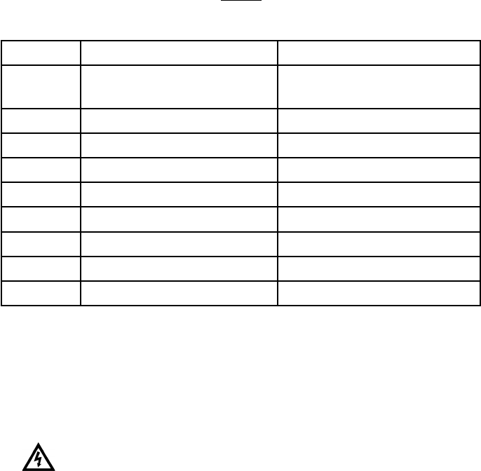
Table B
Authorized Cables with Minimum Lengths
NOTE: This table is for reference only. In order to comply with FCC Part 15
Certification, the installer must insure that actual coax cable used
between the DC injector and the amplifier has at least 3.3 dB of
insertion loss.
Caution: If the power output from the amplifier exceeds +24 dBm or
the antennas used are in excess of 24 dBi gain, the FCC
regulatory limits specified in Part 15.247(b)(3)(i) could be
exceeded.
epyTelbaCssoL/htgneLmuminiMshtgneLdednemmoceRxaM
U/85GR
591RML Bd4.3/teeF91teeF04
002RMLBd4.3/teeF02teeF05
042RMLBd3.3/teeF52teeF56
004RMLBd4.3/teeF05teeF011
005RMLBd5.3/teeF06teeF051
006RMLBd5.3/teeF08teeF081
009RMLBd5.3/teeF021teeF062
0021RMLBd4.3/teeF051teeF053
0071RMLBd4.3/teeF002teeF084
NOTE:
1. MPE distance figures are based on a conservative “worst case” prediction, i.e.
+24 dBm into antenna using formula S=EIRP/(4piR2) and no calculaton for duty
factor. In practice the minimum distance will be much shorter.
2. The minimum MPE distance has been calculated for the maximum allowed
Power Density (S) limit os 1.0 mW/cm2 in the Frequency range 1500 - 100,000
MHz for uncontrolled environments (Ref. 2).
Reference:
1. FCC Part 15, sub-clause 15.247 (b)(4)
2. FCC OET Bulletin 65, edition 97-01
3. FCC Supplement C to OET Bulletin 65, edition 97-01
IMPORTANT:
Only mount the
amplifier with the
connectors facing
downward. Do not
mount it with the
connectors facing
sideways or upwards.
The amplifier can be mast mounted using the steel U-bolt included with the unit. Refer to the
drawing at the end of the manual for a cabling diagram. In outdoor applications, the amplifier
must be installed with the connectors facing downward. Use an open-end wrench to
carefully tighten the bolts using the included nuts. Take care not to over-tighten the bolts.
Alternately, the amplifier can be mounted to a flat surface using any of the mounting holes on
the brackets mounting flanges. However, for maximum reliability the connectors should be
facing downward.
It is very important to waterproof the RF connectors on the amp. However, it is recommended
that you do not tape the connectors until after all system tests have been performed. Be sure
to use a high quality weather resistant electrical tape and/or other water sealant method.
Silicon sealants are not recommended since they are hard to work with, do not ensure a 100%
waterproofing of the connectors and difficult to remove if ever necessary.
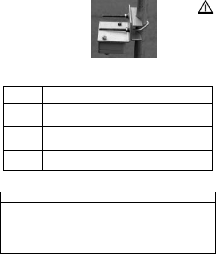
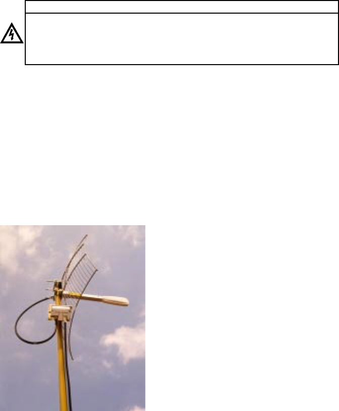
The picture to the left shows the amplifier in typical
installation shown with the YDI Model PT2421 Grid
Dish antenna vertically polarized. The location on the
mast where the amplifier is mounted is not important:
provided that the connectors face downward. (Note
that when this picture was taken, the connectors
were not taped yet nor was the cable secured to
the mast.) Also, there is not need to plug or fill any
of the holes on the back of the amplifier enclosure.
The housing is designed such that these holes do not
penetrate the inside of the waterproof seal even
though an initial inspection might make you think
otherwise.
If the tower or mast is adequately grounded and the
U-bolt makes good electrical connection to it, then
there is no need to provide additional grounding to the
amplifier enclosure.
The DC Power Injector is not in a waterproof enclosure and must be protected from the
weather. It can be permanently mounted to a surface using the mounting flanges. If it is not
mounted to a well-grounded metal plate or bulkhead, then a separate ground strap will need to
connect to the grounding stud on the Injector.
Page 4
APPENDIX B: FCC Part 15 Certified Systems
Page 11
FCC ID#: NM5-LUC2400E
Table A
Authorized Antennas
FCC certified systems consist of:
· A2440-xxF amplifier, DC Injector and 12 VDC Power supply
· Orinoco/Lucent WLAN card with the FCC ID#: IMRWLPCE24H
· Outdoor Antenna (Table A)
· Coax Cable (Table B)
This equipment complies with FCC radiation exposure limits set forth for an
uncontrolled environment when installed as directed. This equipment should be
installed and operated with fix-mounted antennas that are installed such that the
main lobe(s) of these antennas will have a minimum of 2 meters of separation
distance between the antenna and all persons’ body during normal operation.
Safety Notice
Refer to the Typical Installation Detail drawing at the end of this manual for more information
about the installation.
ledoMepyTannetnA annetnA niaG )iBd(
PRIE )mBd( ecnatsiDEPM )MC(
42-ID-42UOAtnecuLannetnAhsiDdirG428417
4242TPIDYannetnAhsiDdirG428417
1242TPIDYannetnAhsiDdirG125405
81PF54.2AIDYannetnAlenaPtalF812463
51PF54.2AIDYannetnAlenaPtalF519352
21PF54.2AIDYannetnAlenaPtalF216302
71PL54.2AIDYannetnAlenaPgnoL711423
41PL54.2AIDYannetnAlenaPgnoL418332
2142AIDYannetnAinmO216302
01-DO-42UOAtnecuLannetnAinmO014302
0142AIDYannetnAinmO014302
8042AIDYannetnAinmO93302
548551EXtnecuLannetnAinmO60302
B-21-AW-UOAtnecuLannetnAelgnAediW214202
81PF54.2AIDYannetnAelgnAediW214202
A21PS4.2AIDY lenaPtalFdeifilpmA annetnA 214202

5. Amplifier Connections and Indicators
CAUTION: Only use high quality N-type connectors. Do not use PL259 “CB” type UHF
connectors. Doing so will ruin the N-Female jacks and void your warranty.
This LED glows RED when the amp has switched to the transmit mode.
This occurs when the amp detects RF power at the jack labeled “To
DC Injector”. (See Section 9 operation for more information)
This LED glows GREEN in the receive mode when DC power is applied
to the amplifier. It is goes off when; the amp is in the transmitting
mode.
This N-type female connects to the DC Power Injector via the transmis-
sion cable. The length of this cable will determine the type of cable
that should be used. See the installation diagram and the Appendix for
more information.
Transmit LED:
Receive LED:
Antenna
Connection:
DC Injector
Connection:
6. DC Power Injector Operation
A DC Power Injector is an in-line device which “injects” the DC power necessary to operate
the amplifier onto a transmission line. This allows the coax cable to carry both RF signals and
DC power to the mast-mounted amplifier. This precludes the need to run a separate power
cable to the remote mounted amplifier.
Page 5
This N-type female connects to the antenna with a short length of
low-loss coax cable.
When grounded to a good earth ground through either the grounding stud or mounting flange,
the DC Injector will provide maximum lightning protection to your radio modem, wireless LAN
card or Access Point.
Page 10
APPENDIX A: Calculating Power
This appendix explains how to calculate the input power to the amplifier for your configuration.
1. Using Table A, convert the output power of the radio modem from Watts (or milliWatts) to
dBm. The Model 2440 amplifier works with input powers between 3.2 mW, +5 dBm, and
100 mW (+20 dBm).
2. Calculate the cable attenuation for your installation.
First, determine the attenuation for the length of your cable at 2.4 GHz. Use the cable
manufacturer’s specifications, or for convenience you may refer to Table B for typical values.
(For example, Table B shows that typical attenuation for LMR-400 is about 6.9 dB per 100 foot
at 2.4 GHz.) Then add 0.6 dB to that figure for connector, adaptor cable, and DC injector
losses.
3. Calculate the maximum power that can be expected at the amp on the pole:
Radio output (dB) - Cable loss (dB) - Connector Loss = Signal level at the amp’s input (dBm)
For example, a radio with 40mW (+16 dBm) output and 75 feet of LMR400 (about 3.4 dB of
loss) would have the following input level to the amplifier:
+16 dBm - 3.4 dB - 0.6dB = +10 dBm
Using a standard amplifier with 14 dB of linear transmit power gain, the output power is
calculated as follows:
+10 dBm + 14 dB gain = +24 dBm output power (250 mW)
If the input to the amplifier will exceed +20 dB (100 mW) by your calculations, an attenuator
pad will be necessary between the modem and the DC injector. Or you can order a special
version of the amplifier from YDI that will accept higher transmit input power.
Note: Never put attenuator pads between in the cable the DC injector and the amplifier since
there is a +12V DC voltage on the cable. Doing this would prevent DC power from
reaching the amp and will also damage the attenuator. However, a longer cable or
one with higher loss could be used.
Effective Radiated Power (ERP)
ERP is defined as the sum of the power feeding an antenna and the gain (in dBi) of that
antenna. For example, with 250 mW (+24 dBm) of power into a 24 dBi gain grid dish antenna
(like the YDI PT2424), the ERP would be:
+24 dBm + 24 dB = 48 dBm or 64 watts EIRP

7. DC Power Injector Connections and Indicators
This LED glows RED when the pole mounted amplifier goes into transmit
amplification mode. The Remote Transmit LED is controlled by unique
circuitry, which actually detects changes in the DC current traveling through
the transmission line to the amplifier. When you see this LED flash, you will
know that the remote pole amplifier is going into transmit mode.
This LED glows GREEN when DC power is applied to the amplifier and it is
in the receive mode. When toggling between transmit and receive this LED
will glow slightly dimmer.
This N-type female connects to the radio via a short jumper cable.
This N-type female connects to the amplifier on the mast using the coax
transmission line.
This is the DC power input for the injector and is a standard 2.1 mm barrel
jack. +12VDC should be applied with center positive.
This jack parallels the 12 VDC jack power jack. It can be used to provide 12
VDC to the radio modem or Access Point using a short DC jumper cable.
Provided that the radio device operates on 12 VDC and draws less then 600
ma, the standard DC power supply that comes with the amplifier kit can be
used to power both it and the amplifier/DC Injector. This extra jack is
installed when the DC-INJ-DUAL option is ordered.
Red Transmit LED:
Green Receive
LED:
“To Radio”
Connection:
“To Amplifier”
Connection:
12 VDC:
AUX 12VDC:
8. Power Supply
The AMP2440 kit comes with a 100 to 240 VAC power supply that has a standard 2.1 mm
barrel plug [center pin positive (+) tip and outer ring negative (-)]. Although normally supplied
with a power supply, any 12 Volt DC, 1 amp (or greater) regulated power supply can be used.
The amplifier can operate from 11 to 14 VDC enabling battery or vehicle operation as well.
Page 6
The DC power input is diode protected to prevent damagecaused by reverse polarity input
voltages as well as by an TVS to protect it and the amp from overvoltage surges.
dBm
0
1
2
3
4
5
6
7
8
9
10
11
12
13
14
15
16
17
18
19
20
21
22
23
24
25
Watts
1.0 mW
1.3 mW
1.6 mW
2.0 mW
2.5 mW
3.2 mW
4.0 mW
5.0 mW
6 mW
8 mW
10 mW
13 mW
16 mW
20 mW
25 mW
32 mW
40 mW
50 mW
64 mW
80 mW
100 mW
128 mW
160 mW
200 mW
250 mW
320 mW
Watts
400 mW
500 mW
640 mW
800 mW
1.0 W
1.3 W
1.6 W
2.0 W
2.5 W
3.0 W
4.0 W
5.0 W
6.0 W
8.0 W
10 W
13 W
16 W
20 W
25 W
32 W
40 W
50 W
64 W
80 W
100 W
1000 W
dBm
26
27
28
29
30
31
32
33
34
35
36
37
38
39
40
41
42
43
44
45
46
47
48
49
50
60
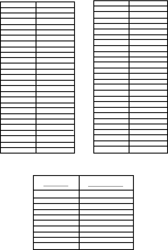
Table A - Conversions from dBm to Watts
Table B - Typical Cable Attenuation Values
These values are approximate. Check with cable manufacturers for exact specifications.
Page 9
Cable Type
Belden 9913
LMR 200
LMR 240
LMR 400
LMR 600
1/2” LDF
1/2” Superflex
3/8” LDF
3/8” Superflex
1/4” Superflex
Attenuation per 100 ft
at 2.4 GHz (dB)
8.0
16.8
12.9
6.9
4.4
3.9
6.1
5.9
6.8
9.8
9. Operation
The unit operates automatically and there are no user adjustments.
The amplifier is only intended for use with 2.4 GHz radio modems that alternate between
transmit and receive in the same radio channel. These are referred to as Time Division
Multiplex (TDD) devices. A typical example is an 802.11 WLAN card or Access Point. These
modems “ping-pong” back and forth between transmit and receive so quickly during normal
operation that both the TX and RX LEDs will appear to be lit simultaneously. In fact they are
turning on and off so quickly that they appear to be on all the time. You can tell the duty cycle
one of these LEDs by their brightness.
The amplifier will not work with radio modems or wireless bridges that are band-split true full
duplex devices.
The amplifier provides linear amplification for transmit output powers up to at least 400 mW.
This is important for Direct Sequence Spread Spectrum (DSSS) radios, especially 802.11
devices. If you drive the amp so hard as to exceed 400mW output power, the amplifier will
start to go into compression. This will result in raising the sidebands which will result in
polluting the adjacent radio channels.
For Frequency Hopping Spread Spectrum radio devices, versions of the amplifier are available
from the that have the output power limited to 250, 400 or 500 mW as specified in the FCC
certified system. These amplifiers should not be used with DSSS radios since the transmit
power limiting mechanism in the amplifier will cause it to go into compression when their
respective clamped output levels are reached.
Page 7 Page 8
ANTENNA
Omni-directional (shown),
Grid Dish, panel Yagi Antennas (not shown)
or
AMP2440
(mounted to mast with U-Bolt)
N-female connector
Transmission Line
LMR-400 (Up to 100 feet)
LMR-500 or LMR-600 (Up to 150 feet)
LMR-1200 (Up to 300 feet)
Mast
Drip
Loop
()
CAB-LL
Drawings\diagrams\install-amp-Generic
DC POWER
INJECTOR
Radio Modem,
Access Point,
WLAN Card, etc
Short length of RG58/U
RF + DC
110/220 VAC
N-female
N-femaleConnector required
by radio
DC P.S.
Barrel Plug
12 VDC Plug
BarrelOptional Jumper Cable
(CAB-DC-2.x)
TYPICAL AMPLIFIER INSTALLATION DETAILS
12 VDC
To Network
YDI can provide all necessary cables,
antennas and accessories. The
professional installer must provide
the mast or pole to mount the
antenna and amplifier
To enable the DC power supply to power both the DC Injector and the radio, the amp kit should be ordered with the
DUAL-DC option along with the appropriate DC Jumper cable.
7. DC Power Injector Connections and Indicators
This LED glows RED when the pole mounted amplifier goes into transmit
amplification mode. The Remote Transmit LED is controlled by unique
circuitry, which actually detects changes in the DC current traveling through
the transmission line to the amplifier. When you see this LED flash, you will
know that the remote pole amplifier is going into transmit mode.
This LED glows GREEN when DC power is applied to the amplifier and it is
in the receive mode. When toggling between transmit and receive this LED
will glow slightly dimmer.
This N-type female connects to the radio via a short jumper cable.
This N-type female connects to the amplifier on the mast using the coax
transmission line.
This is the DC power input for the injector and is a standard 2.1 mm barrel
jack. +12VDC should be applied with center positive.
This jack parallels the 12 VDC jack power jack. It can be used to provide 12
VDC to the radio modem or Access Point using a short DC jumper cable.
Provided that the radio device operates on 12 VDC and draws less then 600
ma, the standard DC power supply that comes with the amplifier kit can be
used to power both it and the amplifier/DC Injector. This extra jack is
installed when the DC-INJ-DUAL option is ordered.
Red Transmit LED:
Green Receive
LED:
“To Radio”
Connection:
“To Amplifier”
Connection:
12 VDC:
AUX 12VDC:
8. Power Supply
The AMP2440 kit comes with a 100 to 240 VAC power supply that has a standard 2.1 mm
barrel plug [center pin positive (+) tip and outer ring negative (-)]. Although normally supplied
with a power supply, any 12 Volt DC, 1 amp (or greater) regulated power supply can be used.
The amplifier can operate from 11 to 14 VDC enabling battery or vehicle operation as well.
Page 6
The DC power input is diode protected to prevent damagecaused by reverse polarity input
voltages as well as by an TVS to protect it and the amp from overvoltage surges.
dBm
0
1
2
3
4
5
6
7
8
9
10
11
12
13
14
15
16
17
18
19
20
21
22
23
24
25
Watts
1.0 mW
1.3 mW
1.6 mW
2.0 mW
2.5 mW
3.2 mW
4.0 mW
5.0 mW
6 mW
8 mW
10 mW
13 mW
16 mW
20 mW
25 mW
32 mW
40 mW
50 mW
64 mW
80 mW
100 mW
128 mW
160 mW
200 mW
250 mW
320 mW
Watts
400 mW
500 mW
640 mW
800 mW
1.0 W
1.3 W
1.6 W
2.0 W
2.5 W
3.0 W
4.0 W
5.0 W
6.0 W
8.0 W
10 W
13 W
16 W
20 W
25 W
32 W
40 W
50 W
64 W
80 W
100 W
1000 W
dBm
26
27
28
29
30
31
32
33
34
35
36
37
38
39
40
41
42
43
44
45
46
47
48
49
50
60
Table A - Conversions from dBm to Watts
Table B - Typical Cable Attenuation Values
These values are approximate. Check with cable manufacturers for exact specifications.
Page 9
Cable Type
Belden 9913
LMR 200
LMR 240
LMR 400
LMR 600
1/2” LDF
1/2” Superflex
3/8” LDF
3/8” Superflex
1/4” Superflex
Attenuation per 100 ft
at 2.4 GHz (dB)
8.0
16.8
12.9
6.9
4.4
3.9
6.1
5.9
6.8
9.8

5. Amplifier Connections and Indicators
CAUTION: Only use high quality N-type connectors. Do not use PL259 “CB” type UHF
connectors. Doing so will ruin the N-Female jacks and void your warranty.
This LED glows RED when the amp has switched to the transmit mode.
This occurs when the amp detects RF power at the jack labeled “To
DC Injector”. (See Section 9 operation for more information)
This LED glows GREEN in the receive mode when DC power is applied
to the amplifier. It is goes off when; the amp is in the transmitting
mode.
This N-type female connects to the DC Power Injector via the transmis-
sion cable. The length of this cable will determine the type of cable
that should be used. See the installation diagram and the Appendix for
more information.
Transmit LED:
Receive LED:
Antenna
Connection:
DC Injector
Connection:
6. DC Power Injector Operation
A DC Power Injector is an in-line device which “injects” the DC power necessary to operate
the amplifier onto a transmission line. This allows the coax cable to carry both RF signals and
DC power to the mast-mounted amplifier. This precludes the need to run a separate power
cable to the remote mounted amplifier.
Page 5
This N-type female connects to the antenna with a short length of
low-loss coax cable.
When grounded to a good earth ground through either the grounding stud or mounting flange,
the DC Injector will provide maximum lightning protection to your radio modem, wireless LAN
card or Access Point.
Page 10
APPENDIX A: Calculating Power
This appendix explains how to calculate the input power to the amplifier for your configuration.
1. Using Table A, convert the output power of the radio modem from Watts (or milliWatts) to
dBm. The Model 2440 amplifier works with input powers between 3.2 mW, +5 dBm, and
100 mW (+20 dBm).
2. Calculate the cable attenuation for your installation.
First, determine the attenuation for the length of your cable at 2.4 GHz. Use the cable
manufacturer’s specifications, or for convenience you may refer to Table B for typical values.
(For example, Table B shows that typical attenuation for LMR-400 is about 6.9 dB per 100 foot
at 2.4 GHz.) Then add 0.6 dB to that figure for connector, adaptor cable, and DC injector
losses.
3. Calculate the maximum power that can be expected at the amp on the pole:
Radio output (dB) - Cable loss (dB) - Connector Loss = Signal level at the amp’s input (dBm)
For example, a radio with 40mW (+16 dBm) output and 75 feet of LMR400 (about 3.4 dB of
loss) would have the following input level to the amplifier:
+16 dBm - 3.4 dB - 0.6dB = +10 dBm
Using a standard amplifier with 14 dB of linear transmit power gain, the output power is
calculated as follows:
+10 dBm + 14 dB gain = +24 dBm output power (250 mW)
If the input to the amplifier will exceed +20 dB (100 mW) by your calculations, an attenuator
pad will be necessary between the modem and the DC injector. Or you can order a special
version of the amplifier from YDI that will accept higher transmit input power.
Note: Never put attenuator pads between in the cable the DC injector and the amplifier since
there is a +12V DC voltage on the cable. Doing this would prevent DC power from
reaching the amp and will also damage the attenuator. However, a longer cable or
one with higher loss could be used.
Effective Radiated Power (ERP)
ERP is defined as the sum of the power feeding an antenna and the gain (in dBi) of that
antenna. For example, with 250 mW (+24 dBm) of power into a 24 dBi gain grid dish antenna
(like the YDI PT2424), the ERP would be:
+24 dBm + 24 dB = 48 dBm or 64 watts EIRP

The amplifier can be mast mounted using the steel U-bolt included with the unit. Refer to the
drawing at the end of the manual for a cabling diagram. In outdoor applications, the amplifier
must be installed with the connectors facing downward. Use an open-end wrench to
carefully tighten the bolts using the included nuts. Take care not to over-tighten the bolts.
Alternately, the amplifier can be mounted to a flat surface using any of the mounting holes on
the brackets mounting flanges. However, for maximum reliability the connectors should be
facing downward.
It is very important to waterproof the RF connectors on the amp. However, it is recommended
that you do not tape the connectors until after all system tests have been performed. Be sure
to use a high quality weather resistant electrical tape and/or other water sealant method.
Silicon sealants are not recommended since they are hard to work with, do not ensure a 100%
waterproofing of the connectors and difficult to remove if ever necessary.
The picture to the left shows the amplifier in typical
installation shown with the YDI Model PT2421 Grid
Dish antenna vertically polarized. The location on the
mast where the amplifier is mounted is not important:
provided that the connectors face downward. (Note
that when this picture was taken, the connectors
were not taped yet nor was the cable secured to
the mast.) Also, there is not need to plug or fill any
of the holes on the back of the amplifier enclosure.
The housing is designed such that these holes do not
penetrate the inside of the waterproof seal even
though an initial inspection might make you think
otherwise.
If the tower or mast is adequately grounded and the
U-bolt makes good electrical connection to it, then
there is no need to provide additional grounding to the
amplifier enclosure.
The DC Power Injector is not in a waterproof enclosure and must be protected from the
weather. It can be permanently mounted to a surface using the mounting flanges. If it is not
mounted to a well-grounded metal plate or bulkhead, then a separate ground strap will need to
connect to the grounding stud on the Injector.
Page 4
APPENDIX B: FCC Part 15 Certified Systems
Page 11
FCC ID#: NM5-LUC2400E
Table A
Authorized Antennas
FCC certified systems consist of:
· A2440-xxF amplifier, DC Injector and 12 VDC Power supply
· Orinoco/Lucent WLAN card with the FCC ID#: IMRWLPCE24H
· Outdoor Antenna (Table A)
· Coax Cable (Table B)
This equipment complies with FCC radiation exposure limits set forth for an
uncontrolled environment when installed as directed. This equipment should be
installed and operated with fix-mounted antennas that are installed such that the
main lobe(s) of these antennas will have a minimum of 2 meters of separation
distance between the antenna and all persons’ body during normal operation.
Safety Notice
Refer to the Typical Installation Detail drawing at the end of this manual for more information
about the installation.
ledoMepyTannetnA annetnA niaG )iBd(
PRIE )mBd( ecnatsiDEPM )MC(
42-ID-42UOAtnecuLannetnAhsiDdirG428417
4242TPIDYannetnAhsiDdirG428417
1242TPIDYannetnAhsiDdirG125405
81PF54.2AIDYannetnAlenaPtalF812463
51PF54.2AIDYannetnAlenaPtalF519352
21PF54.2AIDYannetnAlenaPtalF216302
71PL54.2AIDYannetnAlenaPgnoL711423
41PL54.2AIDYannetnAlenaPgnoL418332
2142AIDYannetnAinmO216302
01-DO-42UOAtnecuLannetnAinmO014302
0142AIDYannetnAinmO014302
8042AIDYannetnAinmO93302
548551EXtnecuLannetnAinmO60302
B-21-AW-UOAtnecuLannetnAelgnAediW214202
81PF54.2AIDYannetnAelgnAediW214202
A21PS4.2AIDY lenaPtalFdeifilpmA annetnA 214202
3. Amplifier Kit
Each Amplifier Kit Includes:
• Bi-directional remote mounted amplifier
• DC Power Injector
• 12 VDC, 110/220 VAC Power Supply
• Stainless Steel U-Bolts and mounting
bracket for amp
• Installation Manual
Close up of the bracket and mounting
hardware attached to the amplifier.
The following options are also available and must be ordered separately:
DC power cable with 2.1mm plug to flying lead 3 feet long. Used when the
customer provides their own 12 VDC power for the DC injector or amp.
Option to add second power jack on DC injector to enable one 12 VDC PS
that comes with the amp to power both the Injector and the radio or AP.
(Requires a DC jumper cable. See below).
DC jumper cable that connects a radio modem or Access Point to the
second DC power jack on the DC injector box. Radio devices must have a
2.1 mm ID power jack and operate on 12VDC.
Same as above except used for radios and Access Points that have a 2.5
mm ID barrel jack on them.
4. Installation and Cabling Instructions
FCC Notice
To comply with FCC part 15 rules, the proper version of the amp must only be used in systems
that have been FCC certified. The system must also be professionally installed to ensure
compliance with the Part 15 certification. It is the resposibility of the professional installer to
ensure that certified systems be deployed in the United States (or where FCC rules apply).
The use of the amplifier in any other combination (such as co-located antennas transmitting
the same information) is expressly forbidden in accordance with FCC rules CFR47 part
15.204. Please visit our web site (www.ydi.com) to see the systems currently certified by the
FCC.
Several key factors unique to their particular installation determine the power level at the input
of the amplifier. The most important consideration is the cable loss in the transmission cable
between the radio and the pole mounted amp. It is important that the installer understand these
and other factors when installing the system.
If you are not familiar with determining power levels within the transmission system, YDI
engineers will assist you in planning your system including selecting the proper cable and
antenna required.
Page 3
CAB-DC
DUAL-DC
DC-2.1-2.1
DC-2.1-2.5
Page 12
Table B
Authorized Cables with Minimum Lengths
NOTE: This table is for reference only. In order to comply with FCC Part 15
Certification, the installer must insure that actual coax cable used
between the DC injector and the amplifier has at least 3.3 dB of
insertion loss.
Caution: If the power output from the amplifier exceeds +24 dBm or
the antennas used are in excess of 24 dBi gain, the FCC
regulatory limits specified in Part 15.247(b)(3)(i) could be
exceeded.
epyTelbaCssoL/htgneLmuminiMshtgneLdednemmoceRxaM
U/85GR
591RML Bd4.3/teeF91teeF04
002RMLBd4.3/teeF02teeF05
042RMLBd3.3/teeF52teeF56
004RMLBd4.3/teeF05teeF011
005RMLBd5.3/teeF06teeF051
006RMLBd5.3/teeF08teeF081
009RMLBd5.3/teeF021teeF062
0021RMLBd4.3/teeF051teeF053
0071RMLBd4.3/teeF002teeF084
NOTE:
1. MPE distance figures are based on a conservative “worst case” prediction, i.e.
+24 dBm into antenna using formula S=EIRP/(4piR2) and no calculaton for duty
factor. In practice the minimum distance will be much shorter.
2. The minimum MPE distance has been calculated for the maximum allowed
Power Density (S) limit os 1.0 mW/cm2 in the Frequency range 1500 - 100,000
MHz for uncontrolled environments (Ref. 2).
Reference:
1. FCC Part 15, sub-clause 15.247 (b)(4)
2. FCC OET Bulletin 65, edition 97-01
3. FCC Supplement C to OET Bulletin 65, edition 97-01
IMPORTANT:
Only mount the
amplifier with the
connectors facing
downward. Do not
mount it with the
connectors facing
sideways or upwards.

Model 2440 Functional Block Diagram
Receiver Low Noise Amplifier (LNA)
Receive Gain:
Freq Response:
Noise Figure:
16 dB nominal
+/-1 dB over operating range
4 dB typical
Operating Range:
Operating Mode:
Connectors:
Indicators:
Lightning
Protection:
DC Surge
Protection:
2400-2483 MHz
Bi-directional, half-duplex. Senses RF
carrier from transmitter and
automatically switches from receive to
transmit mode.
N-female
TX and RX LEDs on both the amplifier
and the DC bias injector
Direct DC ground at antenna connector.
DC injector serves as lightning arrestor
if properly grounded.
600 Watt TVS at 12 VDC input from
transmis
2.1 General Specifications
Transmitter Amplifier
Transmit Gain:
Freq Response:
Transmit Output
Power:
Duty Cycle:
Transmit Input
Power to Amp:
14 dB nominal for standard amp
(Other versions may have different gains)
+/-1 dB over operating range
250 mW nominal
Up to 640 mW for FHSS radios
Up to 400 mW for DSSS radios
50% Maximum
3mW minimum (+5dBm),
100mW (20 dBm) maximum
(Special versions are available with higher
input power.)
Mechanical, Power and Environmental
Operating
Temperature:
Power:
Dimensions:
Mounting Bracket
for amplifier:
Kit Weight:
-20°C to +60°C
105-240 VAC if using the power
supply provided with the amp kit
or
11 – 14 VDC @ 900 ma peak,
400 ma avg. with an alternate
power source
Amplifier:
4.5” x 2.6” x 1.2 ”
DC Power injector:
5.4” X 2.4” X 1.3 ”
Accommodates pole/mast
diameters
from 3/4” to 3”
Approx. 1.5 lb. with U-bolts
View showing the DC Injector and the
pole mounted outdoor amplifier
attached to its mounting bracket.
Page 2
NOTES:
Page 13

Limited Warranty
Young Design, Inc. (YDI) warrants that your device is free of defects in material and
workmanship for a period of one year after initial purchase. YDI will, in this period of time,
repair or replace, any YDI product returned to the factory, freight prepaid.
The YDI warranty covers repairs or replacement (at YDI’s option) of the product only. YDI is
not responsible for the cost of removal, reinstallation, or shipping to the place of repair. YDI
does not extend or modify its warranty period as a result of repair or replacement.
YDI reserves the right to void a warranty and/or make reasonable charges for the repair of a
unit if the warranty seal is broken or the unit displays evidence of misuse, abuse, or
tampering.
YDI is not responsible for damage to any other equipment or property, or any other
consequential or incidental damages of any kind, whether based on contract, negligence, or
strict liability. Maximum liability shall not in any case exceed the purchase price of the unit.
Warranties give you (the buyer) specific legal rights. You may also have other rights that
vary from state to state. This warranty is only extended to purchases made in the United
States of America or its possessions.
Warranty Notice
The AMP2440 warranty is null and void if any of the following occurs:
1. The amplifier is opened
2. The antenna connections are not properly waterproofed
3. The amplifier is operated with no antenna attached
4. Improper connectors are used
5. The amplifier is mounted outdoors with the connectors facing any direction except
downwards
This device complies with part 15 of the FCC rules. Operation is subject to the
following two conditions: (1) This device may not cause harmful interference, and
(2) this device must accept any interference received, including interference that
may cause undesired operation.
© 2000 Young Design, Inc. All Rights Reserved. No part or parts of this document may be
reproduced, translated, stored in any electronic retrieval system, or transmitted, in any form
or by any means, electronic, mechanical, photocopying, recording, or otherwise, without the
prior written permission of Young Design, Inc.
To see a complete line of our High Speed
Wireless Data products, visit our web site at:
www.ydi.com
or call our Sales Office at:
1-888-297-9090