YDI Wireless LUC2400E Rooftop Fixed Direct Sequence Transmission System User Manual Cover
YDI Wireless Rooftop Fixed Direct Sequence Transmission System Cover
Contents
- 1. Lucent Manual
- 2. Users and Operators Manual
- 3. users manual
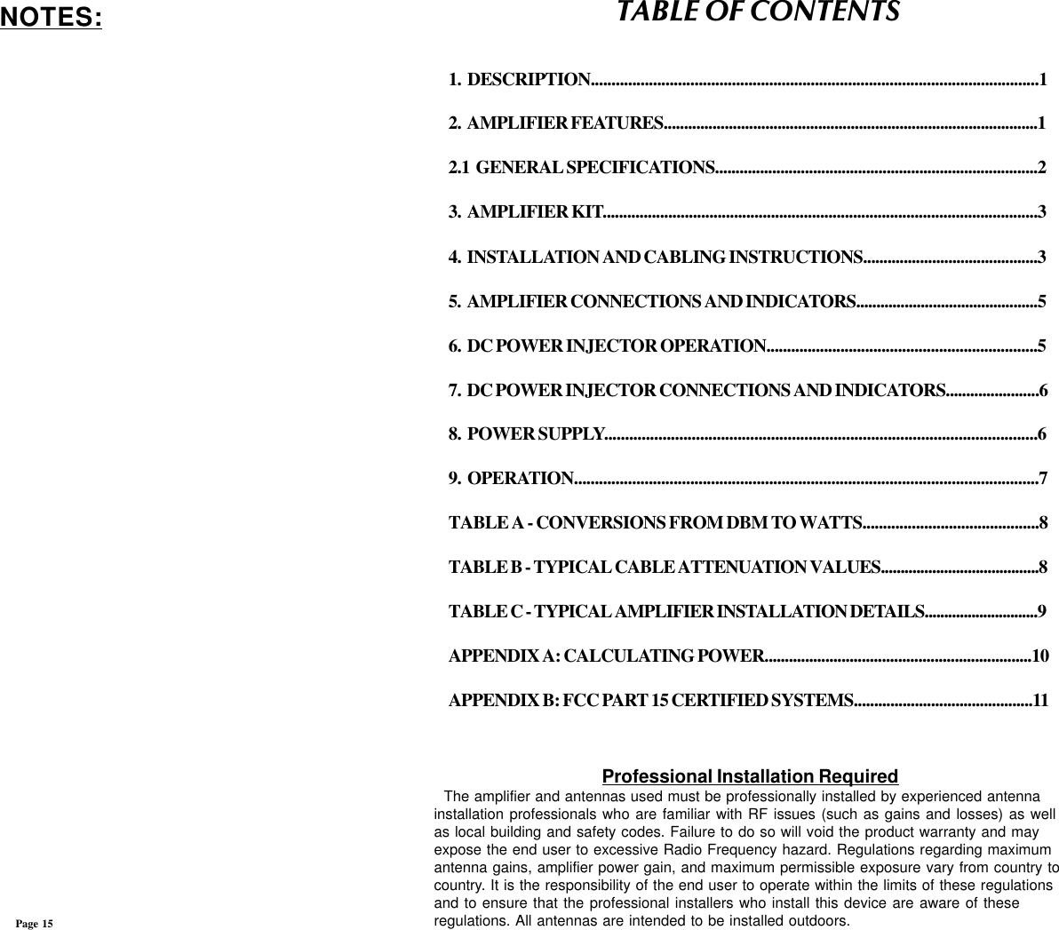
Users and Operators Manual

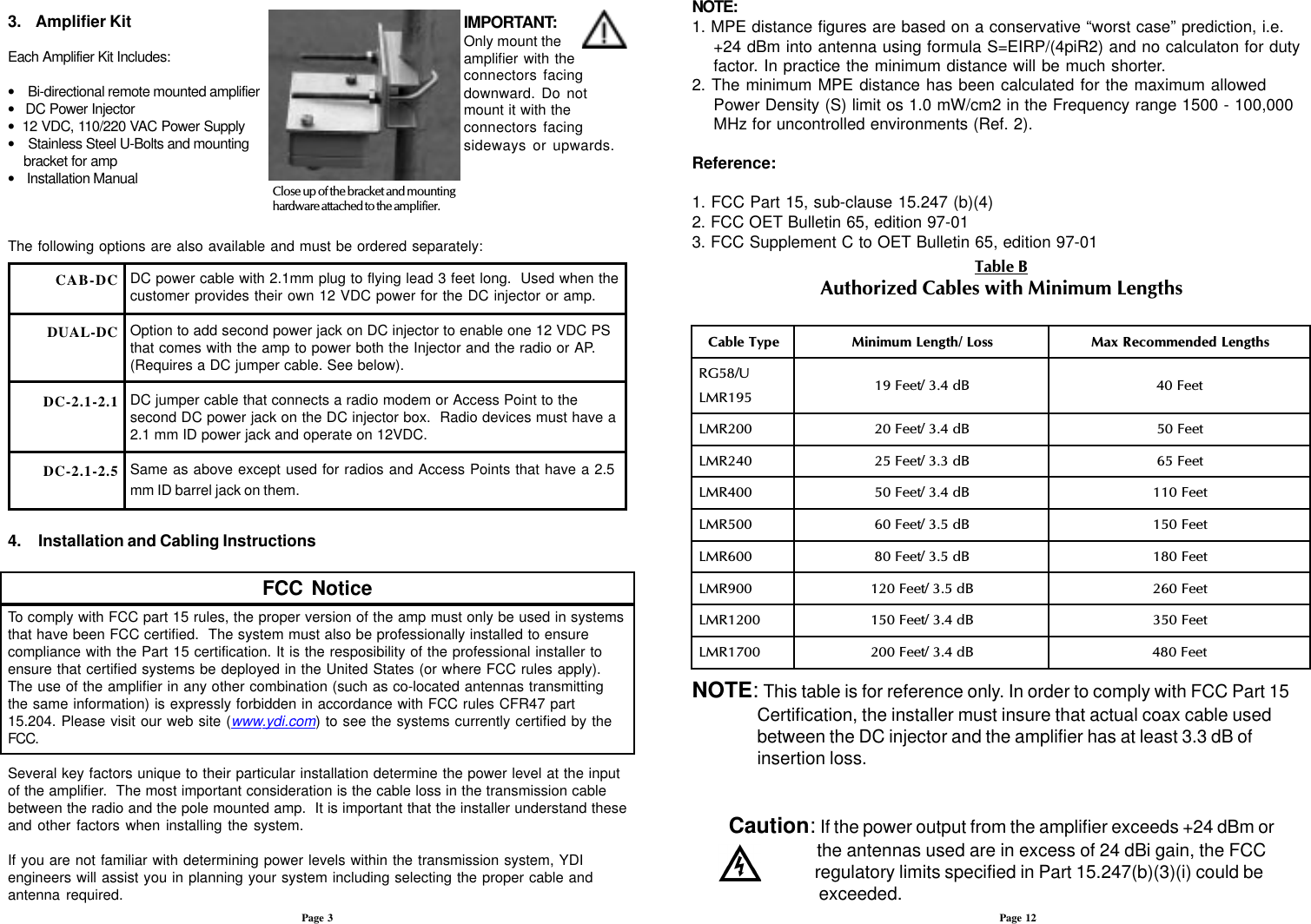


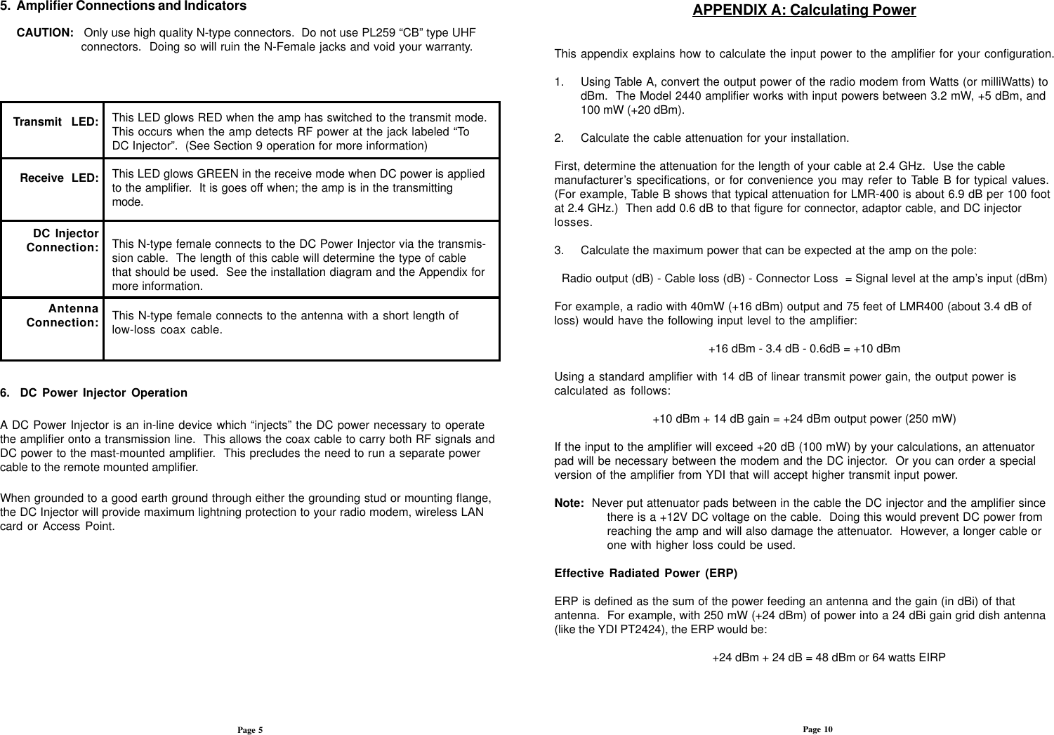
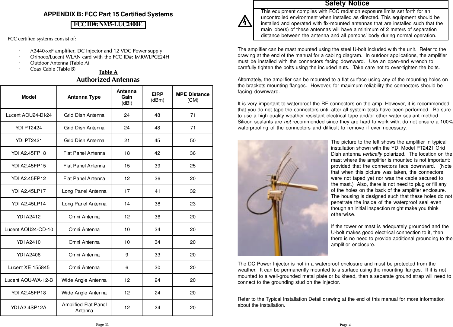
![7. DC Power Injector Connections and IndicatorsThis LED glows RED when the pole mounted amplifier goes into transmit amplification mode. The Remote Transmit LED is controlled by uniquecircuitry, which actually detects changes in the DC current traveling throughthe transmission line to the amplifier. When you see this LED flash, you will know that the remote pole amplifier is going into transmit mode.This LED glows GREEN when DC power is applied to the amplifier and it is in the receive mode. When toggling between transmit and receive this LEDwill glow slightly dimmer.This N-type female connects to the radio via a short jumper cable.This N-type female connects to the amplifier on the mast using the coax transmission line.This is the DC power input for the injector and is a standard 2.1 mm barreljack. +12VDC should be applied with center positive.This jack parallels the 12 VDC jack power jack. It can be used to provide 12VDC to the radio modem or Access Point using a short DC jumper cable.Provided that the radio device operates on 12 VDC and draws less then 600ma, the standard DC power supply that comes with the amplifier kit can beused to power both it and the amplifier/DC Injector. This extra jack isinstalled when the DC-INJ-DUAL option is ordered.Red Transmit LED:Green ReceiveLED:“To Radio”Connection:“To Amplifier”Connection:12 VDC:AUX 12VDC:8. Power SupplyThe AMP2440 kit comes with a 100 to 240 VAC power supply that has a standard 2.1 mmbarrel plug [center pin positive (+) tip and outer ring negative (-)]. Although normally suppliedwith a power supply, any 12 Volt DC, 1 amp (or greater) regulated power supply can be used.The amplifier can operate from 11 to 14 VDC enabling battery or vehicle operation as well.Page 6The DC power input is diode protected to prevent damagecaused by reverse polarity inputvoltages as well as by an TVS to protect it and the amp from overvoltage surges.dBm012345678910111213141516171819202122232425Watts1.0 mW1.3 mW1.6 mW2.0 mW2.5 mW3.2 mW4.0 mW5.0 mW 6 mW 8 mW10 mW13 mW16 mW20 mW25 mW32 mW40 mW50 mW64 mW80 mW100 mW128 mW160 mW200 mW250 mW320 mWWatts400 mW500 mW640 mW800 mW1.0 W1.3 W1.6 W2.0 W2.5 W3.0 W4.0 W5.0 W6.0 W8.0 W10 W13 W16 W20 W25 W32 W40 W50 W64 W80 W100 W1000 WdBm2627282930313233343536373839404142434445464748495060Table A - Conversions from dBm to WattsTable B - Typical Cable Attenuation ValuesThese values are approximate. Check with cable manufacturers for exact specifications.Page 9Cable TypeBelden 9913LMR 200LMR 240LMR 400LMR 6001/2” LDF1/2” Superflex3/8” LDF3/8” Superflex1/4” SuperflexAttenuation per 100 ftat 2.4 GHz (dB)8.016.812.96.94.43.96.15.96.89.8](https://usermanual.wiki/YDI-Wireless/LUC2400E.Users-and-Operators-Manual/User-Guide-133762-Page-9.png)

![7. DC Power Injector Connections and IndicatorsThis LED glows RED when the pole mounted amplifier goes into transmit amplification mode. The Remote Transmit LED is controlled by uniquecircuitry, which actually detects changes in the DC current traveling throughthe transmission line to the amplifier. When you see this LED flash, you will know that the remote pole amplifier is going into transmit mode.This LED glows GREEN when DC power is applied to the amplifier and it is in the receive mode. When toggling between transmit and receive this LEDwill glow slightly dimmer.This N-type female connects to the radio via a short jumper cable.This N-type female connects to the amplifier on the mast using the coax transmission line.This is the DC power input for the injector and is a standard 2.1 mm barreljack. +12VDC should be applied with center positive.This jack parallels the 12 VDC jack power jack. It can be used to provide 12VDC to the radio modem or Access Point using a short DC jumper cable.Provided that the radio device operates on 12 VDC and draws less then 600ma, the standard DC power supply that comes with the amplifier kit can beused to power both it and the amplifier/DC Injector. This extra jack isinstalled when the DC-INJ-DUAL option is ordered.Red Transmit LED:Green ReceiveLED:“To Radio”Connection:“To Amplifier”Connection:12 VDC:AUX 12VDC:8. Power SupplyThe AMP2440 kit comes with a 100 to 240 VAC power supply that has a standard 2.1 mmbarrel plug [center pin positive (+) tip and outer ring negative (-)]. Although normally suppliedwith a power supply, any 12 Volt DC, 1 amp (or greater) regulated power supply can be used.The amplifier can operate from 11 to 14 VDC enabling battery or vehicle operation as well.Page 6The DC power input is diode protected to prevent damagecaused by reverse polarity inputvoltages as well as by an TVS to protect it and the amp from overvoltage surges.dBm012345678910111213141516171819202122232425Watts1.0 mW1.3 mW1.6 mW2.0 mW2.5 mW3.2 mW4.0 mW5.0 mW 6 mW 8 mW10 mW13 mW16 mW20 mW25 mW32 mW40 mW50 mW64 mW80 mW100 mW128 mW160 mW200 mW250 mW320 mWWatts400 mW500 mW640 mW800 mW1.0 W1.3 W1.6 W2.0 W2.5 W3.0 W4.0 W5.0 W6.0 W8.0 W10 W13 W16 W20 W25 W32 W40 W50 W64 W80 W100 W1000 WdBm2627282930313233343536373839404142434445464748495060Table A - Conversions from dBm to WattsTable B - Typical Cable Attenuation ValuesThese values are approximate. Check with cable manufacturers for exact specifications.Page 9Cable TypeBelden 9913LMR 200LMR 240LMR 400LMR 6001/2” LDF1/2” Superflex3/8” LDF3/8” Superflex1/4” SuperflexAttenuation per 100 ftat 2.4 GHz (dB)8.016.812.96.94.43.96.15.96.89.8](https://usermanual.wiki/YDI-Wireless/LUC2400E.Users-and-Operators-Manual/User-Guide-133762-Page-12.png)