YDI Wireless LUC2400E Wireless LAN User Manual NM5 LUC2400E UserManRev2 8
YDI Wireless Wireless LAN NM5 LUC2400E UserManRev2 8
UserManual.wiki
>
YDI Wireless
>
LUC2400E User Manual
>
users manual
Contents
1.
Lucent Manual
2.
Users and Operators Manual
3.
users manual
users manual
Navigation menu
Upload a User Manual
Namespaces
Wiki Guide
HTML
PDF
Info
Views
User Manual
Discussion / Help
Navigation
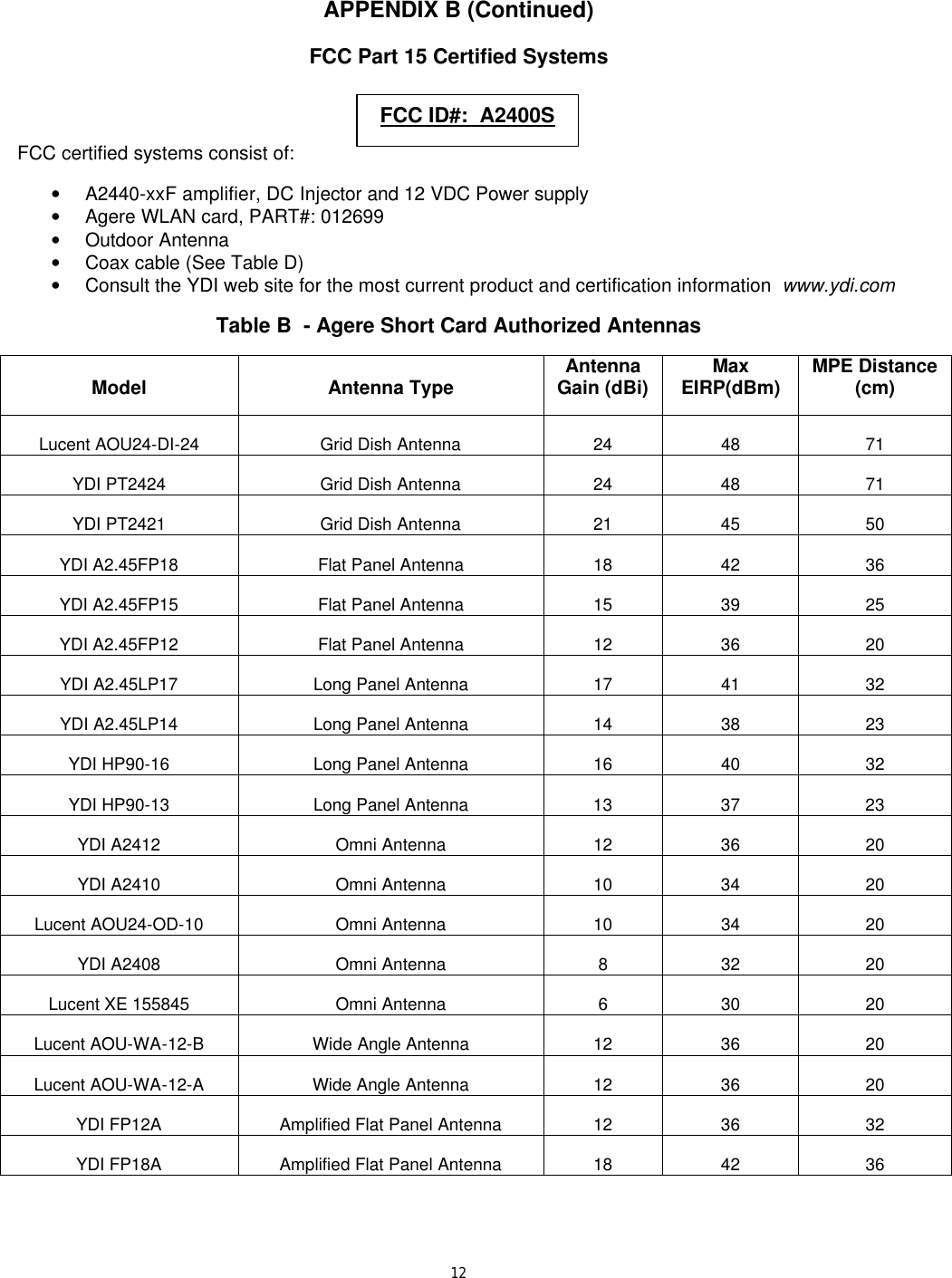
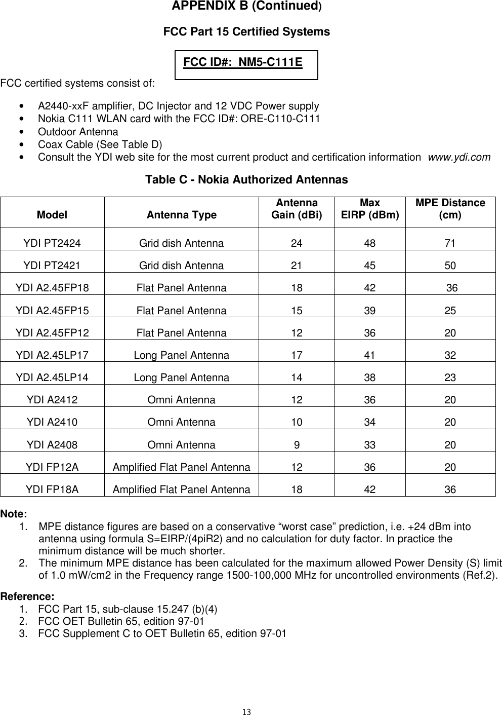
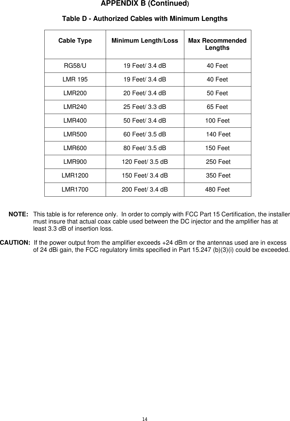
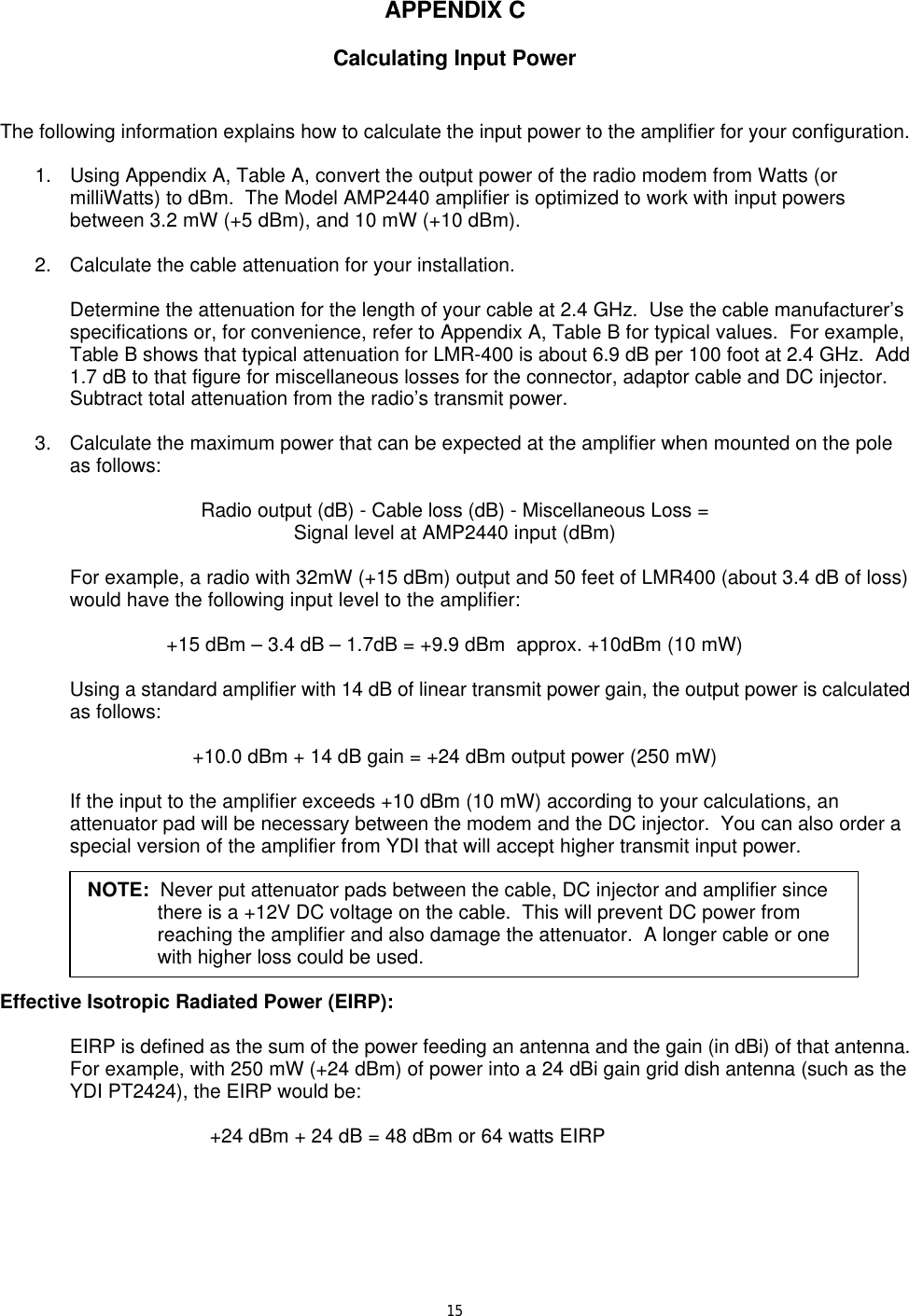
![77.0 DC Power Injector Operation A DC Power Injector is an in-line device that “injects” the DC power necessary to operate the amplifier onto a transmission line. This allows the coax cable to carry both RF signals and DC power to the mast-mounted amplifier. This precludes the need to run a separate power cable to the remote mounted amplifier. When grounded to a good earth ground through either the grounding stud or mounting flange, the DC Injector will provide maximum lightning protection to your radio modem, wireless LAN card or Access Point. 8.0 DC Power Injector Connections and Indicators Red Transmit LED: This LED glows RED when the amplifier goes into transmit amplification mode. The Remote Transmit LED is controlled by unique circuitry, which actually detects changes in the DC current traveling through the transmission line to the amplifier. When the LED flashes, you know that the remote pole amplifier is going into transmit mode. Green Receive LED: This LED glows GREEN when DC power is applied to the amplifier and it goes into receive mode. When toggling between transmit and receive, the LED will glow slightly dimmer. “To Radio” Connection: This N-type female connects to the radio via a short jumper cable. “To Amplifier” Connection: This N-type female connects to the amplifier on the mast using the coax transmission line. 12 VDC: This is the DC power input for the injector and is a standard 2.1 mm barrel jack. +12VDC, center pin positive. AUX 12VDC: (Optional) This jack parallels the 12 VDC power jack. It can be used to provide 12 VDC to the radio modem or Access Point using a short DC jumper cable. The standard DC power supply that comes with the amplifier kit can be used to power both it and the amplifier/DC Injector provided that the radio device operates on 12 VDC and draws less then 600 ma. This extra jack is installed when the DC-INJ-DUAL option is ordered. 9.0 Power Supply The AMP2440 kit comes with a 100 to 240 VAC power supply that has a standard 2.1 mm barrel plug [center pin positive (+) tip and outer ring negative (-)]. Although normally supplied with a power supply, any 12 Volt DC, 1 amp (or greater) regulated power supply can be used. The amplifier can operate from 11 to 14 VDC enabling battery or vehicle operation as well. The DC power input is diode protected to prevent damage caused by reverse polarity input voltages as well as by a TVS to protect it and the amplifier from over-voltage surges.](https://usermanual.wiki/YDI-Wireless/LUC2400E.users-manual/User-Guide-244096-Page-11.png)