Yaesu Musen 03770X30 HF/VHF/UHF TRANSCEIVER User Manual Operating Manual 1
Yaesu Musen Co., Ltd. HF/VHF/UHF TRANSCEIVER Operating Manual 1
Contents
Operating Manual-1
HF/VHF/UHF
ALL MODE TRANSCEIVER
FT-818
Operating Manual

Contents
Introduction .............................................................1
Accessories & Options ............................................2
Supplied Accessories ............................................2
Available Options .................................................2
Plug Pinout ..............................................................3
Installation ...............................................................4
Connecting the Supplied YHA-63 Antenna ..........4
Connecting the Microphone .................................5
Shoulder Strap Installation ...................................5
Rubber Foot Installation .......................................5
Alkaline Battery Installation and Use ...................6
External Power Connections.................................7
SBR-32MH Ni-MH Battery Pack Installation and
Use ........................................................................8
Front Panel Control & Switches ..........................10
Side Panel Switch & Connectors .........................14
Rear Panel Connectors .........................................15
Operation ...............................................................16
Turning the Transceiver On and Off ...................16
Supply Voltage Display ......................................16
Operating Band Selection ...................................17
Mode Selection ..................................................17
Adjusting the Audio Volume Level ....................17
Menu Quick Start ................................................18
Adjusting the RF Gain and Squelch ...................18
Setting the Operating Frequency ........................19
Stacked VFO System ..........................................19
Operation on 5 MHz Band (U.S. Version Only) .20
Clarier (Receiver Incremental Tuning) .............21
Receiver Accessories .............................................21
IF SHIFT .............................................................22
AGC (Automatic Gain Control) .........................23
Noise Blanker .....................................................23
IPO (Intercept Point Optimization) ....................23
ATT (Front End Attenuator) ...............................24
AM/FM DIAL .....................................................24
Automatic Power-Off Feature ............................25
Transmitter Operation .........................................26
SSB Transmission ...............................................26
CW Transmission ................................................28
FM Transmission ................................................31
Digital Mode Operation (SSB-Based AFSK) .....36
Packet (1200/9600 bps FM) Operation...............39
AM Transmission................................................40
Split Frequency Operation ..................................40
Time-Out Timer ..................................................41
WeatherFax Monitoring ......................................41
Memory Operation ...............................................42
QMB Channel .....................................................42
Memory Operation on
“Regular” Memory Channels .............................43
Memory Operation on
“HOME” Channel Memories .............................46
Labeling Memories .............................................47
Spectrum Scope Monitor Operation ...................48
Smart Search™ Operation ...................................49
Scanning Operation ..............................................50
Dual Watch Operation ..........................................54
Operation on Alaska Emergency
Frequency: 5167.5 khz (U.S. Version Only) ........55
Menu Operation ....................................................56
Cloning ...................................................................67
Installation of Optional Accessories ....................68
Optional Filters YF-122S/YF-122C/YF-122CN
...68
Power-on Microprocessor Reset Procedure ........69
Appendix ................................................................70
BAND DATA FORMAT .....................................70
Specications .........................................................71

1FT-818 Operating Manual
The FT-818 is a compact, innovative multiband, multimode portable transceiver for the
amateur radio MF/HF/VHF/UHF bands. Providing coverage of the 160-10 meter bands
(include the 60 m band: USA version) plus the 6 m, 2 m, and 70 cm bands, the FT-818
includes operation on the SSB, CW, AM, FM, and Digital modes, yielding the most com-
prehensive performance package available for portable operation.
Designed for use either from an external DC power source or internal batteries, the FT-
818 provides ve watts of power output from a 13.8-Volt external power supply. When
using the SBR-32MH Ni-MH Battery Pack or 8 “AA” Alkaline Cells (not supplied), the
FT-818 automatically switches to 2.5 Watts of output power. Via the Menu system, “High”
power may be selected during battery operation, providing as much as 6 Watts of output,
depending on the operating frequency.
The multi-function Liquid-Crystal Display includes Blue, Amber, and Violet backlight-
ing, which may be disabled for battery conservation. The display includes bar-graph
indication of power output, ALC voltage, SWR, and modulation level. Also include are a
number of operating status icons, as well as the function displays for the three operating
function keys ( , , and ).
Among the advanced features of the FT-818 are many incorporated only in large
base-station transceivers. These include Dual VFOs; Split-Frequency operation; IF Shift;
Clarier (“R.I.T.”); IF Noise Blanker; AGC Fast/Slow/Auto/Off selection; RF Gain and
Squelch control; IPO (Intercept Point Optimization) and a receiver front-end Attenua-
tor; AM Aircraft reception; AM and FM Broadcast reception; VOX; Built-in Electronic
Keyer; Adjustable CW Pitch; Automatic FM Repeater Shift (ARS); Built-in CTCSS En-
coder/Decoders; ARTS™ (Auto-Range Transponder System); Smart Search™ Automatic
Memory Loading System; Spectrum Scope; 200 Memories plus Home Channels and
Band-limiting Memories; Alpha-Numeric Labeling of Memories; Automatic Power-Off
(APO) and Time-Out Timer (TOT) functions; Computer Interface capability; and Cloning
capability.
We urge you to read this manual in its entirety, so as to gain a full understanding of the
amazing capability of the exciting FT-818 Portable Transceiver.
Introduction

2FT-818 Operating Manual
Supplied acceSSOrieS
MH-31A8J Hand Microphone
SBR-32MH Ni-MH Battery Pack (9.6 V, 1900 mAh)
PA-48B/C/U
Battery Charger
FBA-28 Battery Case
(holds 8 “AA” size Alkaline cells [not supplied])
YHA-63 Whip Antenna for (50/144/430 MHz)
E-DC-6 DC Cable
Shoulder Strap
Ferrite Core
Rubber Foot
available OptiOnS
SBR-32MH Ni-MH Battery Pack (9.6 V, 1900 mAh)
PA-48B/C/U Battery Charger
YF-122S Collins SSB Filter (2.3 kHz/4.7 kHz: –6 dB/–66 dB)
YF-122C Collins CW Filter (500 Hz/2 kHz: –6 dB/–60 dB)
YF-122CN Collins CW Filter (300 Hz/1 kHz: –6 dB/–60 dB)
MH-36E8J DTMF Microphone
CT-62 CAT Interface Cable
CT-39A Packet Cable
: Depends on the transceiver version.
Accessories & Options
3FT-818 Operating Manual
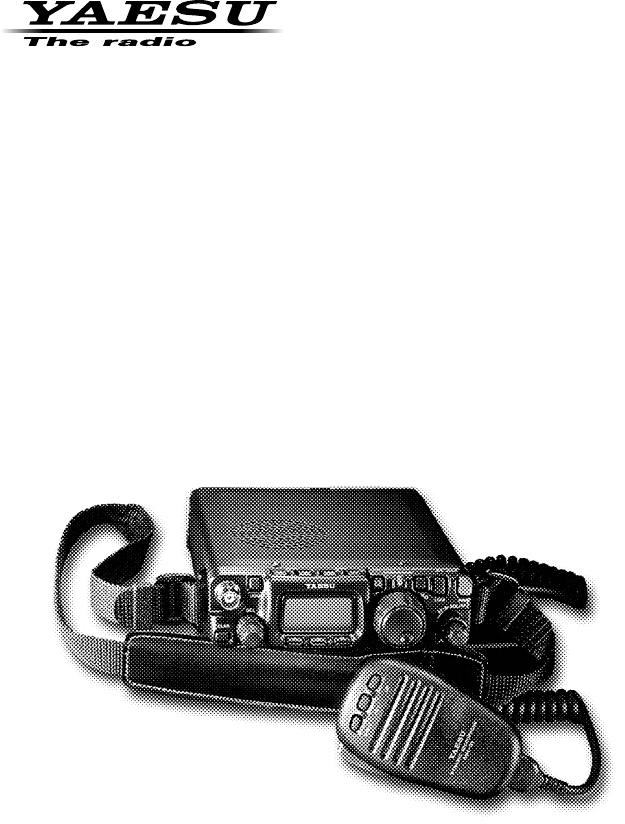
Plug Pinout
DATA OUT
1200bps
DATA OUT
9600bps
SQL
GND
PTT
DATA IN
+13.8V
BAND DATA
ALC
TX INH
RX D
TX D
TX GND
GND
MIC
FAST
GND
PTT
MIC MIC GND
+5 V
UP
DOWN
SIGNAL GND
MIC
KEY
DATA ACC
SP/PH
INPUT DC13.8V
KEY
KEY
NC GND
GND
DOT DASH COMMON
DOT DASH COMMON
4FT-818 Operating Manual
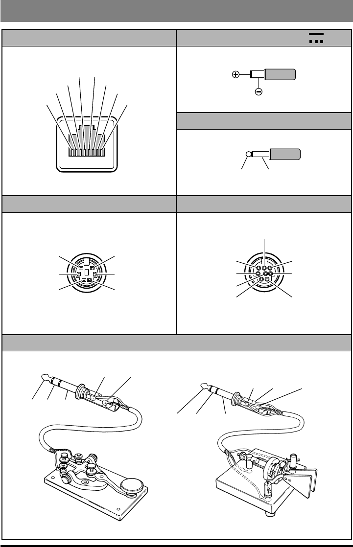
cOnnecting the Supplied Yha-63 antenna
Your FT-818 is supplied with a three-section antenna, model YHA-63 which is designed
for optimum performance on the 50 MHz, 144 MHz, and 430 MHz. It also works well on
the FM broadcast and other VHF bands. This antenna is intended for connection to the
front panel’s BNC-type antenna connector.
For HF and/or 50 MHz operation, most hikers carry their own dipole or collapsible ver-
tical antenna, fed by a small-diameter coaxial cable terminated in a type “M” (PL-259)
plug, and these kinds of antennas may be connected to the rear panel’s antenna connector.
The YHA-63 should be connected to the top panel’s “BNC” connector, using the follow-
ing guidelines:
For 144/430 MHz operation (only), connect the shorter cap section to the screw post
on the top of the main antenna shaft, then screw the assembled YHA-63 onto the BNC
connector, twisting it 1/4 turn clockwise to secure the antenna.
For 50 MHz operation, unscrew the short cap section, and replace it with the long cap
section. The long cap section will provide good results on 144/430 MHz, as well, but
those owners not using 50 MHz may
prefer the shorter total length of the
YHA-63 when using the short cap
on 144/430 MHz.
For shortwave listening using a ran-
dom-length wire antenna for recep-
tion only, you may wish to consider
connection of the wire between the
main YHA-63 shaft and the cap,
using a “spade lug” or similar lug
on the end of the wire to provide a
secure connection between the cap
and the rest of the antenna.
Menu #07 (“ANTENNA”) allows
you to define which connector
(“Front” or “Rear”) is used on a
particular band. See page 58 for
details.
Installation
HF/VHF/UHF ALL MODE TRANSCEIVER
TRANSMIT/BUSY
BAND
DWN UP
MODE
ABC
5FT-818 Operating Manual
Installation
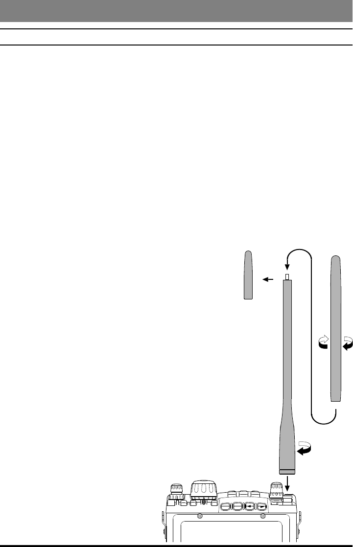
cOnnecting the MicrOphOne
To connect the microphone, plug its
connector (latch side UP) into the
MIC jack on the right side of the
transceiver. Press it gently inward
until you hear the “click” of the
latch.
To disconnect the microphone, press
gently on the “PUSH ” label on
top of the microphone connector’s rubber boot. While pressing on this spot, gently
pull the connector outward from the body of the transceiver.
Note: During “Digital” or “Packet” operation, it is not necessary to disconnect the micro-
phone, as activation of the PTT line from the DATA connector automatically cuts off the
audio input from the MIC jack.
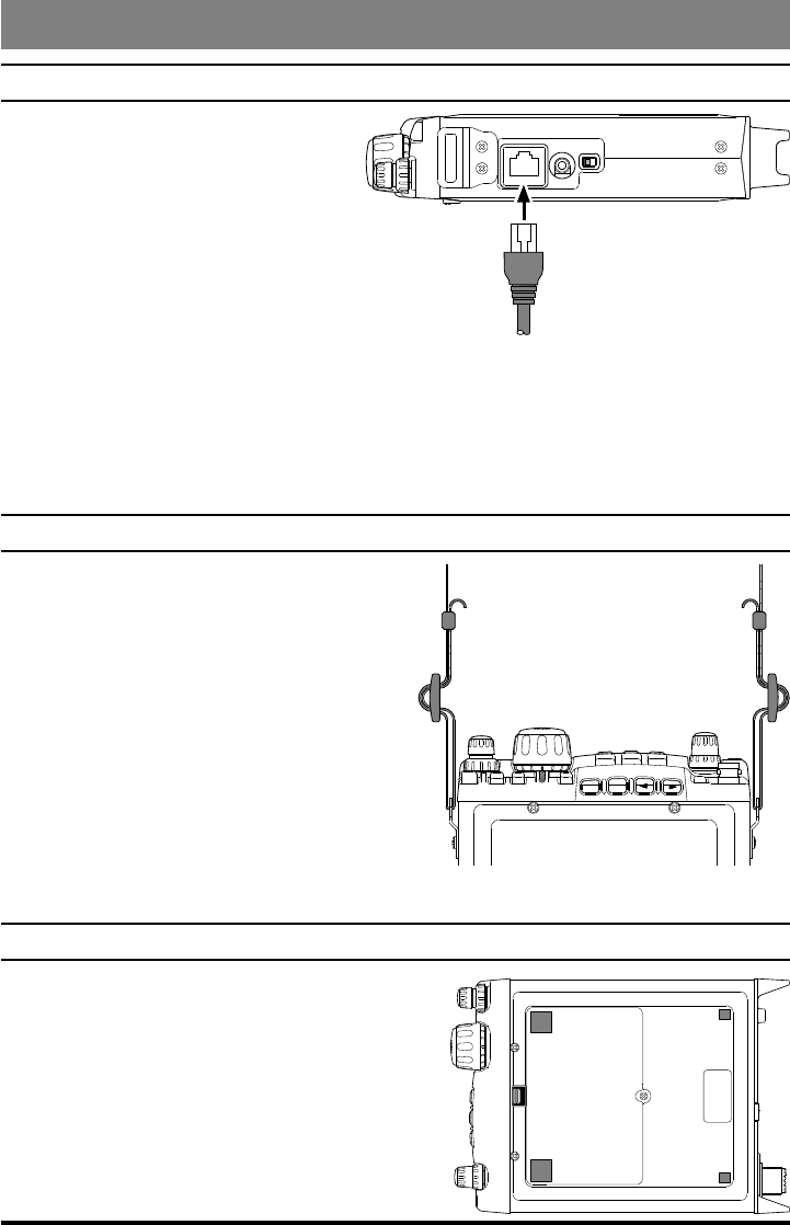
ShOulder Strap inStallatiOn
The convenient Shoulder Strap is designed for
maximum comfort and security for your FT-
818 transceiver.
Refer to the illustration, and connect the
shoulder strap to the attachment tabs just
behind the front panel of the FT-818. Be
sure to have the shoulder strap aligned
correctly, without twists in the straps.
A convenient microphone hanger is locat-
ed on one end of the padded top section of
the Shoulder Strap. When not in use, the
microphone may be afxed here, freeing both of your hands for other tasks.
rubber FOOt inStallatiOn
Four Rubber Feet are provided with your FT-818,
for ease of use when operating from a base station
or camp table.
Refer to the illustration, and afx the Rubber Feet
in the appropriate locations.
MIC
SP/PH SP PH
-
PUSH
HF/VHF/UHF ALL MODE TRANSCEIVER
TRANSMIT/BUSY
BAND
DWN UP
MODE
ABC
FT-817
6FT-818 Operating Manual
Installation
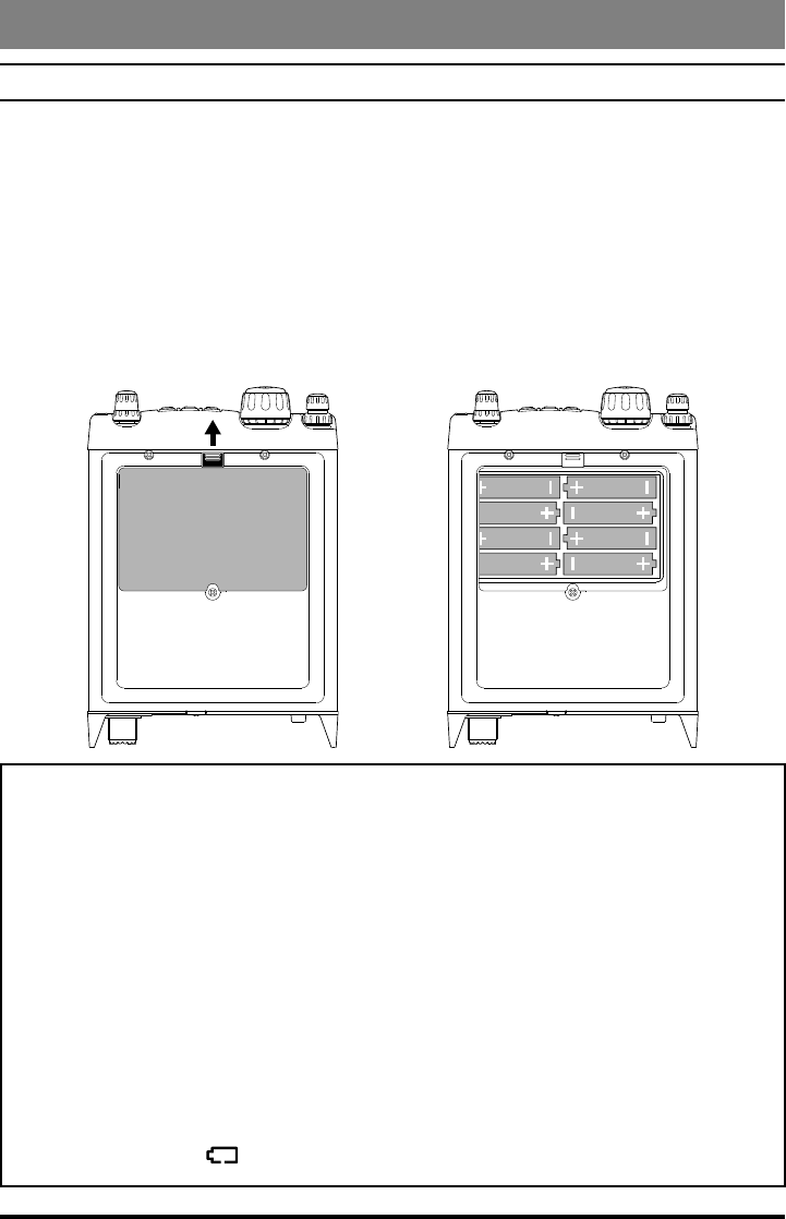
alkaline batterY inStallatiOn and uSe
The FT-818 is supplied with the FBA-28 holder for Alkaline “AA” cells. A fresh set of
Alkaline cells should provide approximately 5.5 hours of reception under typical condi-
tions.
1. To install or replace the AA cells, rst remove the battery cover from the bottom side
of the transceiver. Slide the battery cover latch forward, as shown in the illustration,
then fold the battery cover upward and set it aside temporarily.
2. Install the Alkaline AA cells as shown in the illustration, paying particular attention to
the correct polarity of the batteries.
3. When all batteries have been successfully installed, replace the battery cover.
Important Notes
When the transceiver is to be stored for a long period of time without use (longer
than ten days), remove the batteries from the FBA-28 holder, to avoid the pos-
sibility of battery leaking causing damage to the transceiver. Inspect the FBA-
28 battery holder occasionally for signs of corrosion or battery leakage, and
remove the batteries immediately if any such damage is observed.
The FBA-28 battery holder is designed for use solely with Alkaline type “AA”
cells. Do not attempt to use Ni-Cd or other rechargeable cells in the FBA-28,
because it does not contain the protection circuitry required when using re-
chargeable cells.
When replacing batteries, replace all eight AA cells simultaneously with fresh
batteries.
When the battery voltage is approaching the value which indicates depletion is
near, the small “ ” will blink, indicating it is time to replace the batteries.
7FT-818 Operating Manual
Installation
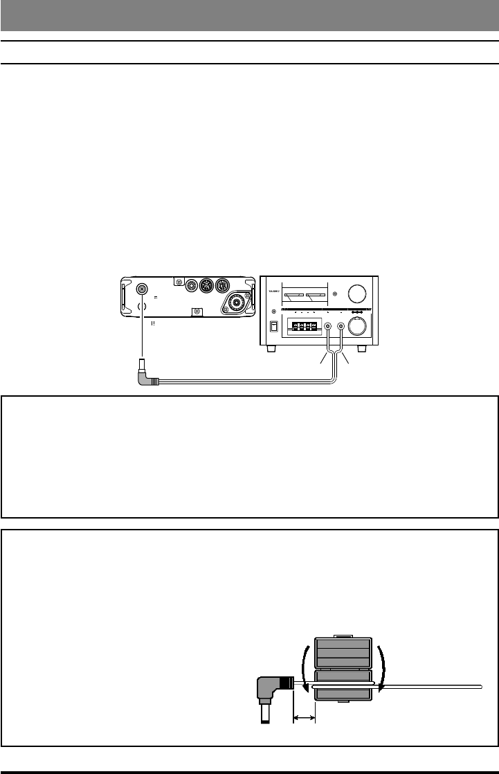
external pOwer cOnnectiOnS
The FT-818 may be connected to an external 13.8 Volt DC power source providing at
least 3 Amps of continuous-duty current.. The supplied E-DC-6 DC cable may be used
for DC connections.
While connected to an external DC source, if you have installed the supplied SBR-32MH
Ni-MH Battery Pack, the E-DC-6 connection to the external DC power source will allow
operation of the FT-818 while charging of the SBR-32MH is in progress.
When making DC power connections, be absolutely certain to follow the markings on the
E-DC-6 so as to ensure proper polarity of the connection to the power supply. Connect
the Red and Black or White and Black wire to the Positive (+) power supply terminal,
and connect the Solid Black wire to the Negative (-) power supply terminal.
V A
0 05 510 2015 3020 40
CONTINU OUS CURRENT 25A
OVE RLOA D
POW ER
ON
OFF
POWERSUPPLY
FP
-
1030
A
6A 25A 10A
FP-1030A
Supplied DC Cable (E-DC-6)
RED/BLACK
or
WHITE/BLACK
BLACK
GND
KEY DATA ACC
ANT
:
INPUT DC13.8V
INPUT DC13.8V
FT-818
Notice
Be extremely careful when making power supply connections. Use only a 13.8
Volt DC Supply, and carefully observe the proper electrical polarity. Serious dam-
age may result if these precautions are not observed.
The Limited Warranty on this product does not cover damage caused by improper
power supply connections, or improper power supply voltage.
Important Note
Occasionally, the 430 MHz transmit signal may behave abnormally when the FT-
818 is operated using an External Power Supply and the whip antenna, especially
with the antenna in close proximity to surrounding metal objects.
If abnormal transmitter operation is ex-
perienced, wind one turn of the E-DC-
6 DC cable around the supplied ferrite
core, and snap its two halves together,
per the illustration below. Install the
core as close as possible to the DC
plug, as shown.
E-DC-6 DC Cable
as close as possible
wind one turn,
snap two halves
8FT-818 Operating Manual
Installation
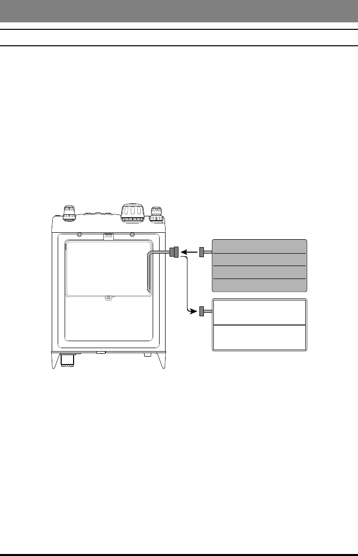
Sbr-32Mh ni-Mh batterY pack inStallatiOn and uSe
The supplied SBR-32MH Ni-MH Battery Pack provides 9.6 Volts of DC power for your
FT-818, with a maximum capacity of 1900 mAh.
Installation
1. To install the SBR-32MH Ni-MH Battery Pack, rst remove the battery compartment
cover, as described previously.
2. Lift out the FBA-28 battery holder, and disconnect the short cable connected to the
FBA-28, as shown in the illustration.
3. Connect the short cable to the mating connector on the SBR-32MH, and install the
SBR-32MH in the battery compartment.
4. Replace the battery compartment cover.
FBA-28
SBR-32MH
9FT-818 Operating Manual
Installation
Charging
Charging of the SBR-32MH requires the use of either the supplied battery charger (PA-
48B/C/U), or an external 13.8 Volt (±15%) DC source. If the battery charger is used, the
FT-818 must be turned off during charging; if an external 13.8 Volt DC source is used
(connected via the supplied E-DC-6 cable), then you may operate the FT-818 while
charging is in progress.
1. Turn the FT-818 off, then connect the supplied battery charger DC connector to the
INPUT: 13.8V jack on the rear panel of the FT-818.
2. Plug the battery charger into the nearest AC wall outlet.
3. Press the FT-818’s switch for one second to turn the transceiver on.
4. Press the key momentarily.
5. Rotate the knob so that the function row containing “[CHG, VLT, DSP]” appears
on the display.
6. Press the key to select the [CHG] option (the display will immediately revert to
the regular frequency display).
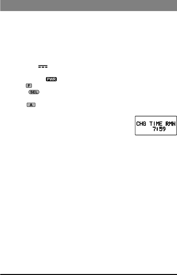
7. Turn the FT-818 off. The display will indicate “CHG TIME
RMN” and remaining time to indicate the time remaining be-
fore a full charge is achieved on the SBR-32MH.
Important Note
The
PA-48 are not designed to power the transceiver for operation (reception or trans-
mission).
Please be advised that the PA-48 may contribute noise to TV and radio reception in
the immediate vicinity, so we do not recommend its use adjacent to such devices.
10 FT-818 Operating Manual
CLAR
E
L
S
A B C
F
V
LOCK PWR
SQL/RF
AF
HOME
M
⑮
⑭ ⑬ ⑨ ⑦ ② ③
⑫ ⑪ ⑩ ⑧ ⑥ ⑤ ④ ①
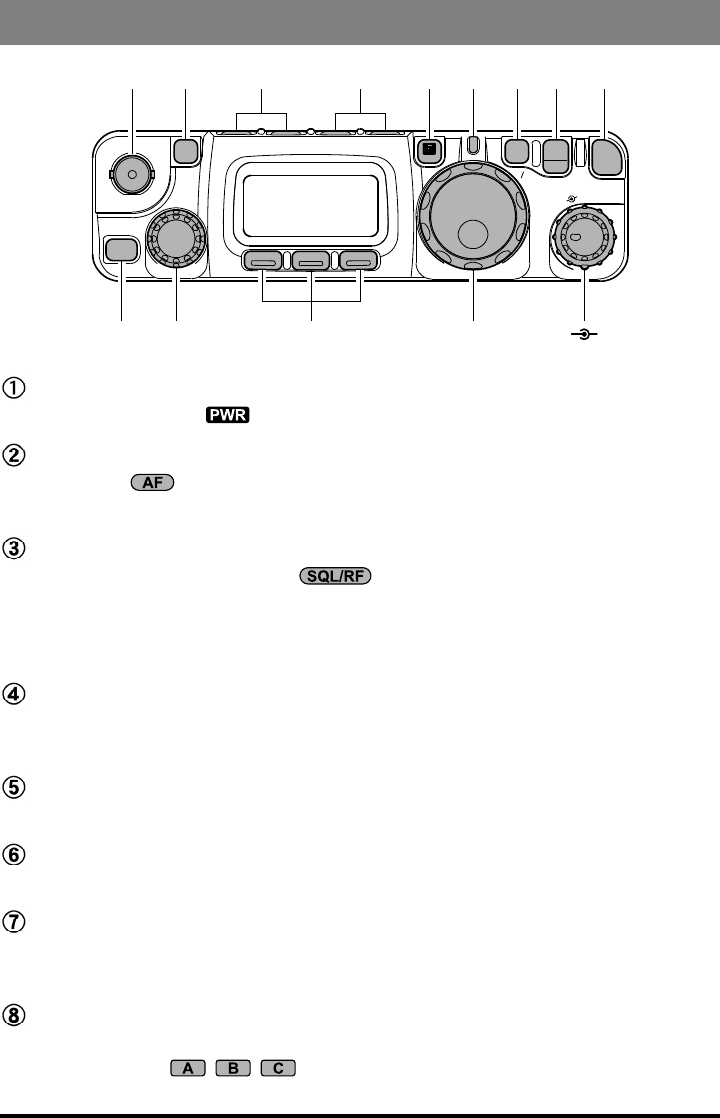
PWR Switch
Press and hold in the switch for one second to turn to the transceiver on or off.
AF Knob
The (inner) knob adjusts the receiver audio volume level presented to the inter-
nal or external speaker. Clockwise rotation increases the volume level.
SQL/RF Knob
In the USA version, this (outer) knob adjusts the gain of the receiver’s RF
and IF stages. Using Menu Selection 45, this control may be changed to function as
a Squelch control, which may be used to silence background noise when no signal is
present. In the other versions, its default setting is set to “Squelch.”
LOCK Key
Pressing this key locks the front panel keys so as to prevent accidental frequency
change.
V/M Key
Pressing this key switches frequency control between the VFO and Memory Systems.
TRANSMIT/BUSY Indicator
This LED glows green when the squelch opens, and turns red during transmit.
MAIN Dial
This is the main tuning dial for the transceiver. It is used both for frequency tuning as
well as “Menu” setting in the transceiver.
F Key
Pressing this key momentarily changes the display to show the operating functions
available via the , , keys.
Press and hold this key for one second to activate the “Menu” mode.
Front Panel Control & Switches
11FT-818 Operating Manual
Front Panel Control & Switches
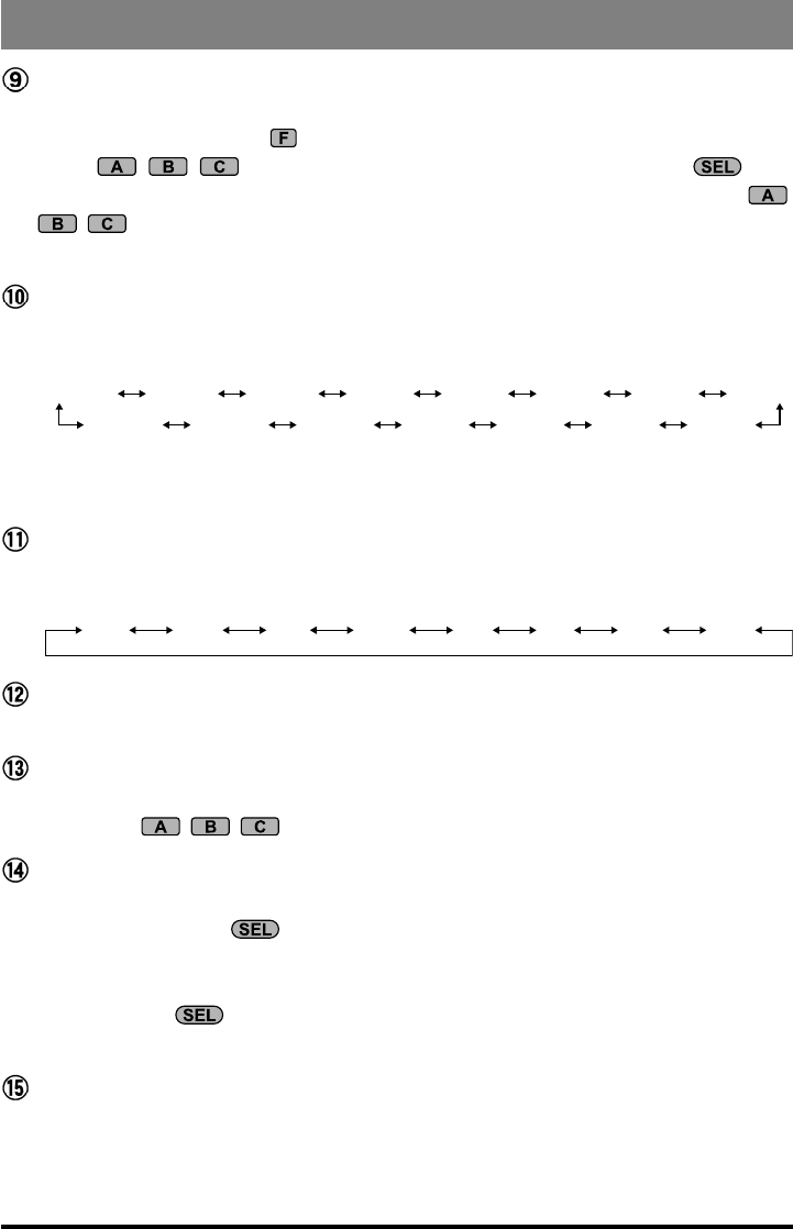
FUNC Keys
These three keys select many of the most important operating features of the trans-
ceiver. When pressing the key, the current function of that key appears above each
of the , , keys (along the bottom of the LCD); rotating the knob
scrolls the display through eleven rows of functions available for use via the ,
, keys.
The available features are shown in chart on the next page.
BAND(DWN)/BAND(UP) Key
Pressing either of these keys momentarily will cause the frequency to be moved up or
down by one frequency band. The selections available are:
1.8 MHz 3.5 MHz 7.0 MHz 10 MHz 14 MHz 15 MHz 18 MHz 21 MHz
24 MHz28 MHz50 MHz88 MHz108 MHz144 MHz430 MHz
Recalling the 5 MHz band (U.S. model) requires different procedure. See page 20
for details.
MODE()/MODE() Key
Pressing either of these keys momentarily will change the operating mode. The selec-
tions available are:
LSB USB CW CWR AM FM DIG PKT
HOME Key
Pressing this key momentarily recalls a favorite “home” frequency memory.
SEL Knob
This detented rotary switch is used for tuning, memory selection, and function selec-
tion for the , , keys of the transceiver.
CLAR Key
Press this key momentarily to activate the Receiver Clarier feature. When this fea-
ture is activated, the knob may be used to set a tuning offset of up to ±9.99
kHz. The transmitter’s frequency is not affected by the setting of the Clarier.
Press and hold this key for 1/2 second to activate the IF Shift feature, which allows
you to use the knob to adjust the center frequency of the IF lter’s passband
response.
ANT Jack
Connect the supplied 50/144/430 MHz rubber ex antenna (or another antenna pre-
senting a 50Ω impedance) to this BNC connector.
In its default setting, this jack does not function on the HF bands. If you want to en-
able this jack on the HF bands, recall and change the setting of Menu #07.
12 FT-818 Operating Manual
Front Panel Control & Switches
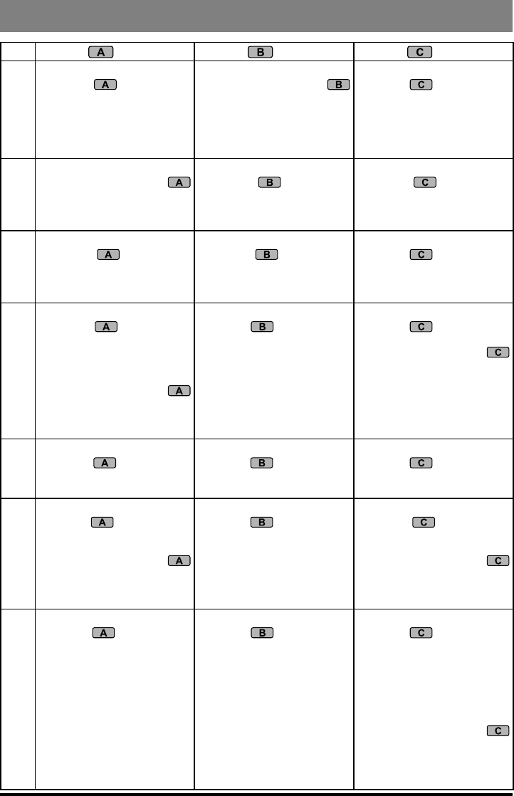
key key key
1
A/B
Press the key to switch
between VFO-A and VFO-B
on the display.
A=B
Press and hold in the
key for 1/2 second to copy the
contents of VFO-A into the
VFO-B register, so that the
two VFOs’ contents will be
identical.
SPL
Press the key to activate
Split frequency operation be-
tween VFO-A and VFO-B.
2
MW
Press and hold in the
key for 1/2 second to transfer
the contents of the VFO into a
Memory register.
MC
Press the key to des-
ignate the current Memory
channel to be “skipped”
during scanning.
TAG
Press the key to select
the display type (Frequency
or Alpha-numeric Tag) during
Memory operation.
3
STO
Press the key to store
the contents of the VFO into
the QMB (Quick Memory
Bank) register.
RCL
Press the key to recall
the QMB Memory.
PMS
Press the key to activate
the Programmable Memory
Scan feature.
4
RPT
Press the key to select
the direction of the uplink
frequency shift (“–,” “+,” or
Simplex) during FM repeater
operation.
Press and hold in the
key for 1/2 second to recall
Menu #42 (for setting the shift
frequency offset).
REV
Press the key to reverse
the transmit and receive
frequencies while working
through a repeater.
TON
Press the key to activate
CTCSS or DCS operation.
Press and hold in the
key for 1/2 second to recall
Menu #48 (for selecting the
CTCSS tone frequency).
5
SCN
Press the key to initiate
scanning (in the direction of
higher frequencies).
PRI
Press the key to activate
the Priority Scan feature.
DW
Press the key to activate
the Dual Watch system.
6
SSM
Press the key to activate
the Spectrum Scope Monitor
feature.
Press and hold in the
key for 1/2 second to recall
Menu #43 (for selecting the
SSM sweep mode).
SCH
Press the key to activate
Smart SearchTM operation.
ART
Press the key to initiate
the Auto-Range Transponder
mode.
Press and hold in the
key for 1/2 second to recall
Menu #09 (for selecting the
ARTS “Beep” option).
7
IPO
Press the key to bypass
the receiver preamplifier,
thereby activating Intercept
Point Optimization for im-
proved overload characteris-
tics.
The IPO feature does not
function on 144/430 MHz.
ATT
Press the key to engage
the receiver front-end atten-
uator, which will reduce all
signals and noise by approxi-
mately 10 dB.
The ATT feature does not
function on 144/430 MHz.
NAR
Press the key to activate
the “Narrow” lter mode in the
CW (optional YF-122C or YF-
122CN required) mode. On
the FM mode, it also selects
the low-deviation mode re-
quired for HF FM operation
on 29 MHz.
Press and hold in the
key for 1/2 second to recall
Menu #38 (to Enable/Disable
the optional lter during instal-
lation).
13FT-818 Operating Manual
Front Panel Control & Switches
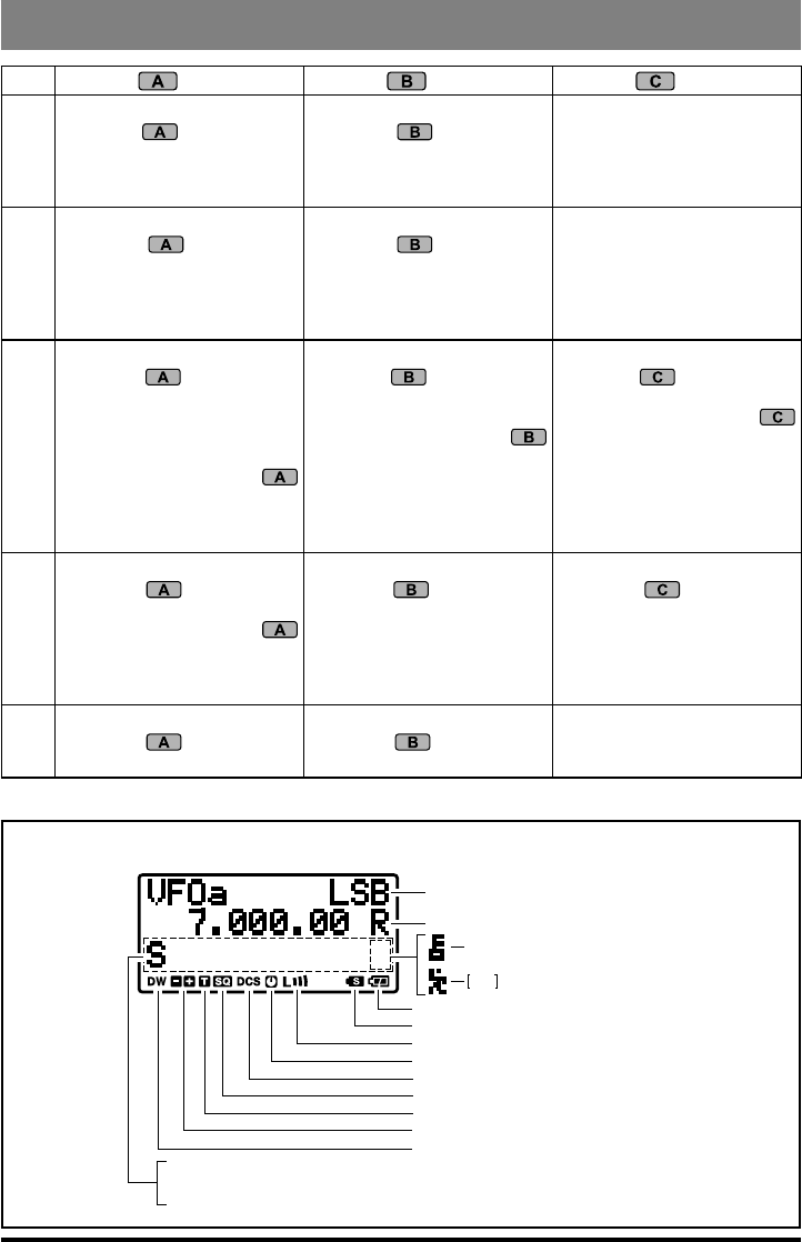
key key key
8
NB
Press the key to activate
the receiver’s IF Noise Blank-
er.
AGC
Press the key to select
the recovery time (FaSt,
SlOw, autO, or OFF) for the
receiver’s AGC system.
–
No function
9
PWR
Press the key to select
the transmitter power output
level (lOw 1, lOw 2, lOw 3, or
high).
MTR
Press the key to select
the display function of the
meter in the transmit mode
(Power, ALC, SWR, or MOD
indication).
–
No function
10
VOX
Press the key to enable
the VOX (voice-operated
transmitter switching system)
in the SSB, AM, and FM
modes.
Press and hold in the
key for 1/2 second to recall
Menu #51 (for setting the
VOX Gain level).
BK
Press the key to activate
CW “Semi” Break-in opera-
tion.
Press and hold in the
key for 1/2 second to recall
Menu #17 (for setting the CW
Delay time). At a setting of 10
ms, operation emulates full
QSK performance.
KYR
Press the key to activate
the built-in Electronic Keyer.
Press and hold in the
key for 1/2 second to recall
Menu #21 (for setting the
Keyer speed).
11
CHG
Press the key to initiate
Battery Charging.
Press and hold in the
key for 1/2 second to recall
Menu #11 (for selecting the
Charging period).
VLT
Press the key to display
the current battery voltage.
DSP
Press the key to switch
the display between the Large
Character and Small Charac-
ter modes.
12
TCH
Press the key to initiate
Tone Search.
DCH
Press the key to initiate
DCS Search.
–
No function
* The Operating Function number in this column does not appear on the LCD.
Display Icons
Operating Mode
S:
PO:
AL:
S-Meter
TX Power Meter
ACL Meter
SW:
MO:
SWR Meter
Deviation Meter
Low Battery!
Split Frequency Operation
Low TX Power Selected
Automatic Power-Off
Digital Coded Squelch
CTCSS Decoder
CTCSS Encoder
Repeater Shift Direction
Dual Watch
Active (page 40
)
(page 26)
Active (page 25)
Active (page 34)
Active (page 32)
Active (page 32)
(page 31)
Active (page 54)
LOCK Feature Active (page 10)
FST Button MH-31 ( ) Active
A8J
Rear Panel Antenna Selected (page 58)
: This operation does not function in the FM Broadcast frequencies.