Yaesu Musen 03770X30 HF/VHF/UHF TRANSCEIVER User Manual Operating Manual 2
Yaesu Musen Co., Ltd. HF/VHF/UHF TRANSCEIVER Operating Manual 2
Contents
Operating Manual-2
14 FT-818 Operating Manual
MIC
SP/PH SP PH
-
① ② ③
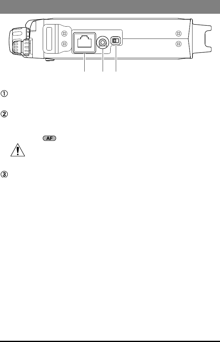
MIC Jack
Connect the supplied MH-31A8J Hand Microphone to this jack.
SP/PH Jack
This 3.5-mm, 2-pin jack provides variable audio output for an external speaker (4 Ω -
16 Ω impedance) or earphones. The audio level varies according to the setting of the
front panel’s knob.
When you insert an earphone plug into this jack, the SP-PH slide switch
(located to the right side of this jack) MUST BE set to the “PH” position, to
prevent the possibility of injury to your ears.
SP-PH Switch
If you use earphones with this transceiver, move this switch to the “PH” position be-
fore inserting the earphone plug into the SP/PH Jack, to prevent injury your ears.
Side Panel Switch & Connectors
15FT-818 Operating Manual
Rear Panel Connectors
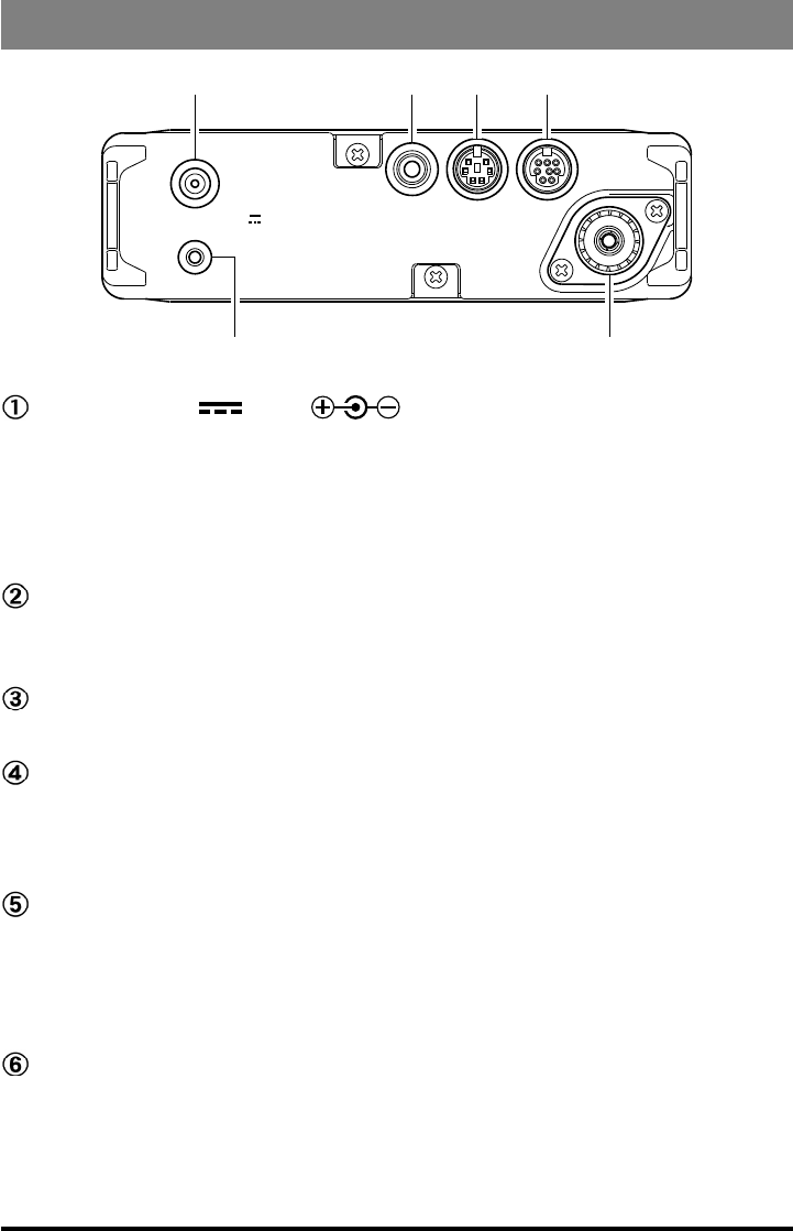
GND
KEY DATA ACC
ANT
:
INPUT DC13.8V
②
③
⑥
⑤④①
INPUT:13.8V Jack ()
This is the DC power supply connection for the transceiver, used when operating the
transceiver with an external power supply. Use the supplied DC cable to connect this
jack to the car battery or base station DC power supply, which must be capable of
supplying at least 3A @ 8 ~ 16 VDC. This jack is also used for battery charging (when
using the supplied SBR-32MH battery pack).
GND Terminal
For best performance and safety, this Ground lug may be connected to a good earth
ground using a short, heavy, braided cable.
KEY Jack
This 3.5-mm, 3-pin jack is used for connection to a CW keyer paddle or a straight key.
DATA Jack
This 6-pin, mini-DIN jack accepts AFSK input from a Terminal Node Controller
(TNC); it also provides fixed-level Receiver Audio Output, Push-To-Talk (PTT),
Squelch Status, and ground lines.
ACC Jack
This 8-pin, mini-DIN jack provides a closure to ground during transmission, ALC, a
transmitter-inhibit pin, and “band data” for connection to an external amplier. It is
also used for Transceiver-to Transceiver Cloning and for control of this transceiver
using a personal computer.
ANT Jack
Connect your HF and/or 50 MHz antenna’s 50 Ω coaxial cable to this M-type (“SO-
239”) connector.
In its default setting, this jack does not function on 50/144/430 MHz bands. If you
want to enable this jack on 50/144/430 MHz bands, recall and change the settings of
Menu #07.

16 FT-818 Operating Manual
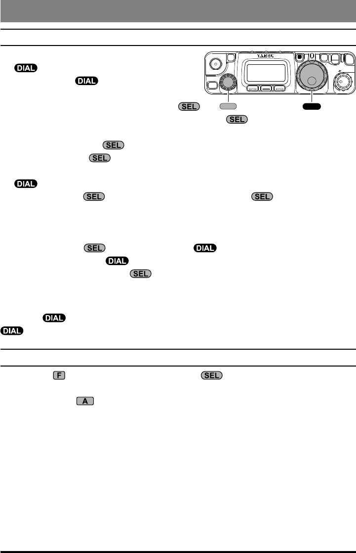
turning the tranSceiver On and OFF
1. To turn the transceiver on, press and hold in
the switch for one second.
2. To turn the transceiver off, again press and
hold in the switch for one second.
The one-second delay helps you avoid accidental
switching on (or off) of DC power.
SupplY vOltage diSplaY
When you turn on the transceiver, the DC supply voltage is indi-
cated in the upper right corner of the LCD for two seconds. After
this interval, the display will resume its normal indication of the
operating mode (VFOa, VFOb, or Memory Channel Number).
To view the supply voltage at any time during operation:
1. Press the key momentarily, then rotate the knob to select Operating Function
Row 11* [CHG, VLT, DSP] on the display.
2. Press the (VLT) key momentarily to display the supply voltage in the upper right
corner of the LCD.
3. To cancel the supply voltage display, again press the (VLT) key.
Remember, the Operating Row Number does not appear on the display.
If you have not operated your FT-818 within the past week, we recommend that you
plug in the Battery Charger, and perform a 10 hour (use for PA-48B/C/U) charge
cycle, to ensure that the SBR-32MH is ready for operation when you are.
CLAR
E
L
S
A B C
F
V
LOCK PWR
SQL/RF
AF
HOME
M
PWR
Operation
17FT-818 Operating Manual
Operation
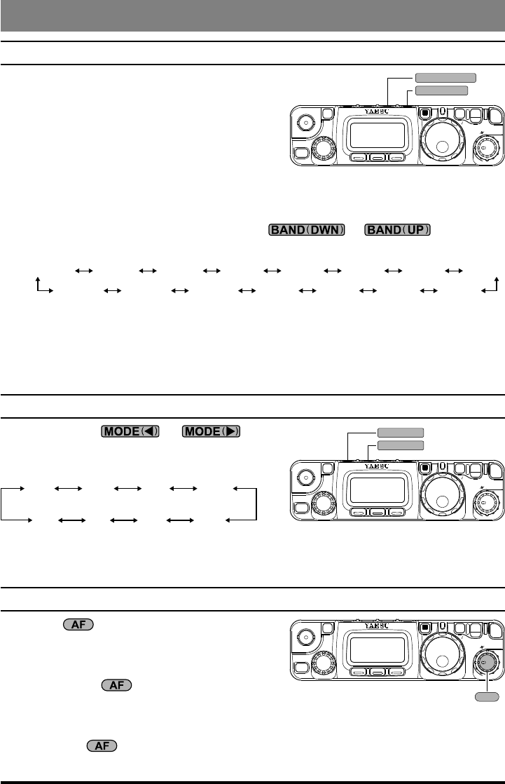
Operating band SelectiOn
This transceiver covers an incredibly wide fre-
quency range, over which a number of different
operating modes are used. Therefore, this trans-
ceiver’s frequency coverage has been divided into
different operating bands, each of with has its own
pre-set channel steps and operating modes. You
can change the channel steps and operating mode once you get started, of course, per the
next section.
To change the frequency band, press either the or key to move
to the next lower or higher operating band, respectively.
1.8 MHz 3.5 MHz 7.0 MHz 10 MHz 14 MHz 15 MHz 18 MHz 21 MHz
24 MHz28 MHz50 MHz88 MHz108 MHz144 MHz430 MHz
1) Recalling the 5 MHz band (U.S. model) requires different procedure. See page 20
for details.
2) VFOa and VFOb are independent VFOs, so they may be set to different bands. See
the “Stacked VFO System” discussion on page 19 for details.
MOde SelectiOn
Press either the or key to
move among the eight settings for the operating
modes, respectively.
LSB USB CW CWR
AM FM DIG PKT
You can also set VFOa and VFOb to different modes in the same band, allowing you to
have a “Phone” VFO and a “CW” VFO, for example.
adjuSting the audiO vOluMe level
Rotate the knob to set a comfortable listen-
ing level.
When operating in the “DIG” or “PKT” modes,
you may set the knob to any comfortable
setting, or even all the way off, because the output
from the DATA jack is a xed-level audio signal.
Start with the knob set fully counter-clockwise, especially when using FM (the
background noise on FM can be surprisingly loud)!
CLAR
E
L
S
A B C
F
V
LOCK PWR
SQL/RF
AF
HOME
M
BAND DWN
( )
BAND UP
( )
CLAR
E
L
S
A B C
F
V
LOCK PWR
SQL/RF
AF
HOME
M
MODE
( )
MODE
( )
CLAR
E
L
S
A B C
F
V
LOCK PWR
SQL/RF
AF
HOME
M
AF
18 FT-818 Operating Manual
Operation
Menu Quick Start
Many aspects of this transceiver’s conguration may be customized using the convenient
“Menu” system, which allow you to congure many “set and forget” settings just the way
you want to. A full discussion of the Menu system beings on page 56; for now, here is a
brief discussion on how to change Menu settings:
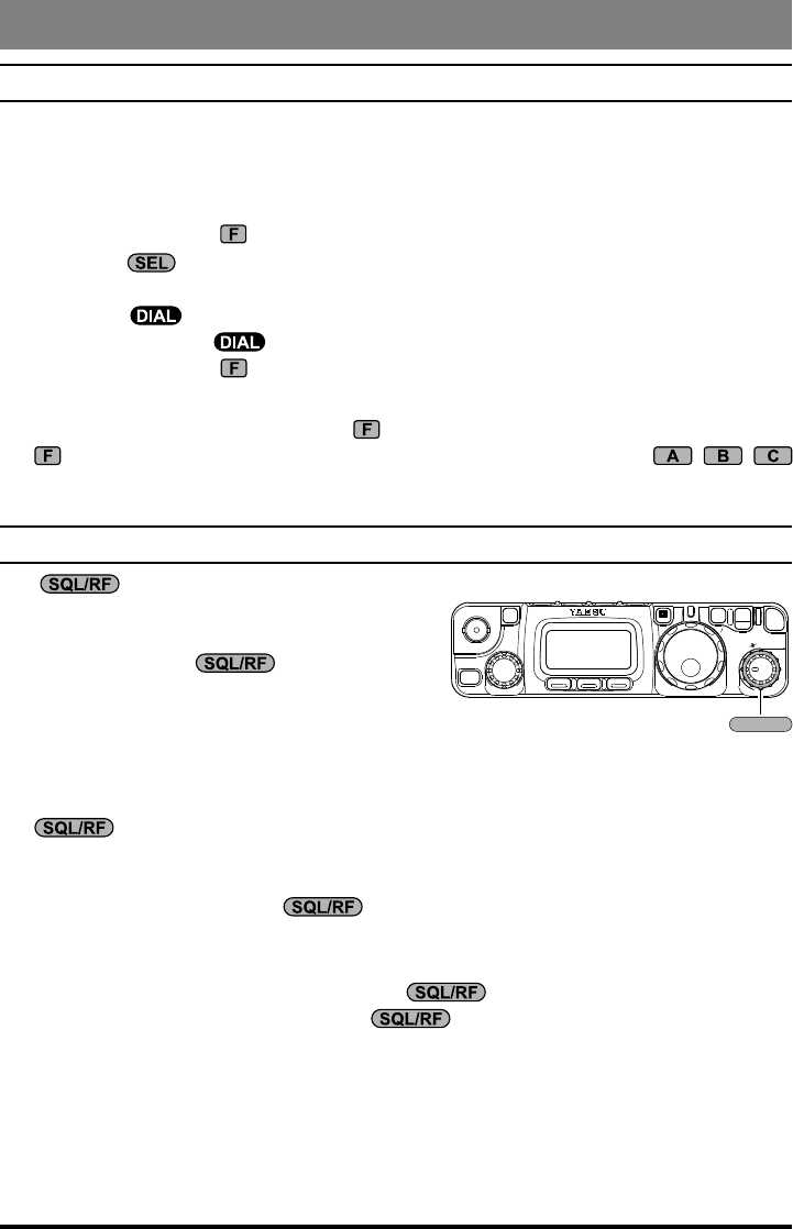
1. Press and hold in the key for one second to enter the Menu mode.
2. Rotate the knob to recall the Menu item to be changed (for example, Menu #01,
which Enables or Disables the Automatic Repeater Shift on the 144 MHz band).
3. Rotate the knob to set this feature (in this example, the default setting is “EN-
ABLE,” so rotate the knob to set this feature to “DISABLE.”
4. Press and hold in the key for one second to save the new setting and exit to normal
operation.
If you have momentarily pressed the key to change an operating function, press
the key momentarily again (to clear the function indications for the , ,
keys) before engaging the Menu.
adjuSting the rF gain and SQuelch
The control is congured differently, depending on the country to which the FT-
818 has been exported. In the U.S. version, the
default function of this control is “RF Gain.” The
configuration of the control is set via
Menu #45; see page 65 for details.
If your transceiver is configured for “RF Gain”
use, rotating this control fully clockwise in the SSB/CW/Digital modes will provide best
sensitivity. To reduce the receiver’s RF Gain somewhat, rotate this control counter-clock-
wise slightly. You will observe an increasing number of bars on the S-meter as you rotate
the control counter-clockwise; this indicates increasing AGC voltage, which is
causing the front-end gain to be reduced. In the FM and Packet modes, this control will
automatically be set to an “Auto-Squelch” mode, wherein the FM/Packet squelch thresh-
old is pre-set at the factory; the control still acts as an “RF Gain” control, how-
ever, and it normally should be set fully clockwise.
If this control is congured for “SQL” operation, the FT-818’s RF Gain will be set for
maximum sensitivity in all modes, and the control will function solely as a
Squelch control. In this case, rotate the control to the point where the back-
ground noise is just silenced; this will provide the best sensitivity to weak signals, while
keeping the receiver quiet when no signal is received. The LED just above the Main Dial
will glow Green when the squelch is opened by an incoming signal or noise.
Note: Squelch operation does not function in the FM Broadcast frequencies.
Battery consumption is signicantly reduced if the receiver is squelched, as the audio
amplier stage is shut off when the receiver is muted.
CLAR
E
L
S
A B C
F
V
LOCK PWR
SQL/RF
AF
HOME
M
SQL/RF
19FT-818 Operating Manual
Operation
Setting the Operating FreQuencY
1. In the “SSB/CW/DIG” modes, rotate the
knob to set the frequency. Clockwise
rotation of the knob increases the oper-
ating frequency.
2. In the “AM/FM/PKT” modes, rotate the
knob to set the frequency. Clockwise rotation of the knob increases the operat-
ing frequency.
3. You may also use the knob to adjust the operating frequency in the “SSB/CW/
DIG” modes. The knob provides faster tuning, ideal for making quick changes
in frequency when you want to move across the band in a hurry. You can then use the
knob to make ne frequency adjustments.
4. If you press the knob momentarily, then rotate the knob, you can now
change the operating frequency in 1 MHz steps, allowing very quick frequency excur-
sions. This can be particularly helpful on the VHF and UHF bands.
5. In step 2 above, it was mentioned that tuning in the “AM/FM/PKT” modes is accom-
plished using the knob. By default, the knob is disabled in these modes; if
you wish to enable the knob in these modes, use Menu #04; see page 58.
6. The synthesizer steps for the knob may be adjusted independently by mode. Use
Menu #06 for AM, #30 for FM, and #47 for SSB/CW/Digital. See pages 58, 62,
and 65 for details.
The main knob synthesizer’s tuning rate (the number of steps per rotation of the
knob) can be adjusted using Menu #33. See page 63 for details.
Stacked vFO SYSteM
1. Press the key momentarily, then rotate the knob, as needed, until Operating
Function Row 1 [A/B, A=B, SPL] appears on the display.
2. Now press the (A/B) key to toggle between the “A” and “B” VFOs. There are
two such VFOs provided on each Amateur band, so you may set VFO-A to the CW
sub-band, and VFO-B to the SSB sub-band, if you like. The operating mode will be
preserved, along with the frequency information, on each VFO.
CLAR
E
L
S
A B C
F
V
LOCK PWR
SQL/RF
AF
HOME
M
SEL DIAL

20 FT-818 Operating Manual
Operation
OperatiOn On 5 Mhz band (u.S. verSiOn OnlY)
The FT-818 includes the capability for transmission and reception on the ve spot frequen-
cies assigned to the Amateur Service in the United States. To operate on the 5 MHz band:
1. Press the key once to enter the “Memory”
mode (a memory channel number “M-nnn”
will appear on the display in the space previ-
ously occupied by “VFOa” or “VFOb”).
2. Rotate the knob to select the desired
channel (“M-601” through “M-605”), at the
factory, with the permitted frequencies in the 5 MHz band.
If you have partitioned your memory channels into Memory
Groups via Menu #34, the memory channel numbers for
60-meter operation will be displayed as “l - 001” ~ “l-005.”
See page 44 for details regarding Memory Group opera-
tion, and page 63 for details regarding Menu #34.
3. Pressing the or key momentarily,
switches the operating mode between SSB and CW.
4. To exit from 60-meter operatin and return to the VFO mode,
just press the key (the memory channel number will be
replaced by “VFOa” or “VFOb”).
The frequencies and operating mode for 5 MHz band operation
are both xed, and may not be changed.
PSK Operation on 5 MHz Band
1. Press the key once, if necessary, to enter the “Memory” mode.
2. Rotate the knob to select the desired channel (“M-601” through “M-
605”), at the factory, with the permitted frequencies in the 5 MHz band.
3. Press the or key to select the SSB mode.
4. When the “transmit” command is received from the TNC, the FT-818 trans-
mitter will be engaged. The microphone input is disabled automatically when
transmitting the PSK signal.
Likewise, the TNC “receive” command will cause the radio to revert to the re-
ceive mode.
You can adjust DATA input level using Menu #25 [DIG MIC].
During PSK operation via the rear panel DATA jack, the front panel MIC jack
is cut off, so you won’t have a “live microphone” problem during data opera-
tion.
Set the PSK sub carrier frequency of the TNC to 1.5 kHz.
Memory Group “OFF”
Memory Group “ON”
CH No. Frequency
M-601 5.3320 MHz
M-602 5.3480 MHz
M-603 5.3585 MHz
M-604 5.3730 MHz
M-605 5.4050 MHz
CLAR
E
L
S
A B C
F
V
LOCK PWR
SQL/RF
AF
HOME
M
SEL
V/M
21FT-818 Operating Manual
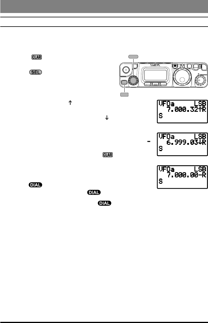
clariFier (receiver increMental tuning)
The Clarier (RIT) allows you to set an offset of up to ±9.99 kHz of the receive frequen-
cy relative to your transmit frequency. To achieve a wider offset than this, you may use
the “Split” operating mode, described later.
1. Press the switch momentarily to activate
the Clarier function.
2. Turn the knob, which allows the receiver
frequency to be varied over a range of 9.99
kHz.
3. When the receiving frequency is higher than
transmit frequency, the “ ” icon will appear at the right of
the frequency display. Similarly, when the receiving frequen-
cy is lower than transmit frequency, the “ ” icon will appear
at the right of the frequency display.
4. When the receiving frequency is equal to transmit frequency
(Clarier offset is zero) while the Clarier is activated, the “
” icon will appear at the right of the frequency display.
5. To turn the Clarier off, again press the switch momen-
tarily. When you turn the Clarier back on, the offset previ-
ously stored will still be applied.
6. To reset the Clarier offset to zero, turn the Clarier off, then
turn the knob by any amount. The Clarier will reset
to zero after the rst “step” of the knob.
If you leave the Clarier on, moving the knob will not cause the offset to be can-
celled.
CLAR
E
L
S
A B C
F
V
LOCK PWR
SQL/RF
AF
HOME
M
SEL
CLAR
[TX < RX]
[TX > RX]
[TX = RX]
Receiver Accessories
22 FT-818 Operating Manual
Receiver Accessories
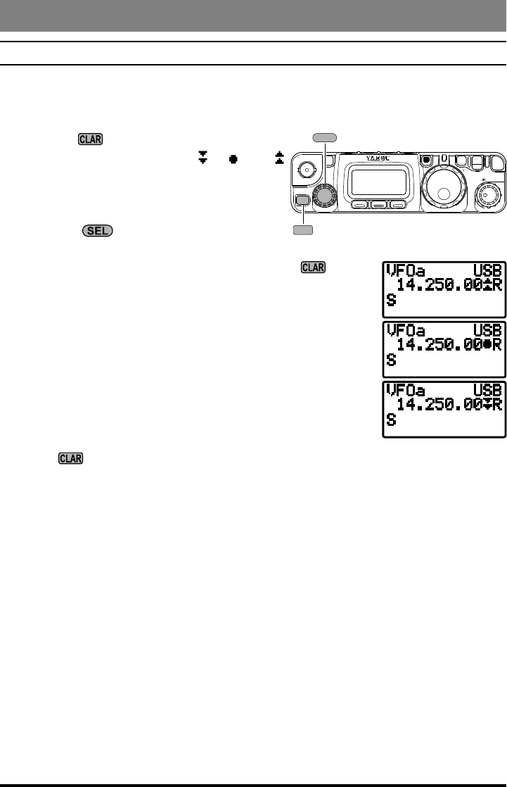
iF ShiFt
The receiver’s IF SHIFT feature is an effective interference-reduction tool, which allows
you to shift the passband response higher or lower without changing the pitch of the in-
coming signal.
1. Press the switch for one second to acti-
vate the IF SHIFT feature. A “ ”, “ ,” or “
” icon will appear at the right of the frequency
display to indicate the IF SHIFT’s current po-
sition.
2. Rotate the knob, as needed, to reduce or
eliminate the interference.
3. To turn the IF SHIFT feature off, again press the switch
for one second. The last setting of the IF SHIFT control will
be retained until you change it again.
4. If you wish to make a more permanent shift in the receiver’s
IF passband, use Menu #54 (LSB) or #55 (USB) in the “Ex-
tended Menu.” This allows you to set up a higher or lower
listening pitch, if you prefer such as compared to the default
passband response. See page 66.
Engaging of the IF Shift feature does not disable the set-
ting of the Clarifier control. With the IF Shift activated,
press the switch momentarily to switch to Clarier operation.
CLAR
E
L
S
A B C
F
V
LOCK PWR
SQL/RF
AF
HOME
M
SEL
CLAR
23FT-818 Operating Manual
Receiver Accessories
agc (autOMatic gain cOntrOl)
The receiver recovery time constant of the AGC system may be modied to match your
operating needs.
1. Press the key momentarily, then rotate the knob, as needed, until Operating
Function Row 8 [NB, AGC] appears on the display.
2. Press the (AGC) key to toggle the AGC recovery time constant among the follow-
ing selections:
“AGCauto” “AGCfast” “AGCslow” “AGCoff” “AGCauto” ……
where “AGCauto” represents “AGCfast” on CW and DIG(AFSK), and “AGCslow” on
the voice modes.
If “AGCoff” selected, the S-meter (which monitors AGC voltage) will cease to function.
nOiSe blanker
The IF Noise Blanker may be useful in reducing or eliminating some types of impulse
noise, especially noise generated by automotive ignition systems.
1. Press the key momentarily, then rotate the knob, as needed, until Operating
Function Row 8 [NB, AGC] appears on the display.
2. Press the (NB) key to activate the Noise Blanker. The “” icon will appear at the
right of the “NB” indication.
3. Press the (NB) key again to turn the Noise Blanker off.
ipO (intercept pOint OptiMizatiOn)
The IPO feature bypasses the receiver RF preamplier, thereby eliminating the preamp’s
gain. This feature is not available on the 144 MHz and 430 MHz.
1. Press the key momentarily, then rotate the knob, as needed, until Operating
Function Row 7 [IPO, ATT, NAR] appears on the display.
2. Press the (IPO) key to bypass the receiver input preamplier. The “” icon will
appear at the right of the “IPO” indication.
3. Press the (IPO) key once more to re-activate the preamp.
On the bands below 14 MHz, the input preamplier is rarely necessary, and activation
of the IPO feature will provide substantial protection against intermodulation and oth-
er problems associated with strong signal input to the receiver. Rule of thumb: so long
as the S-meter is moving on background noise, additional front-end gain is not neces-
sary.