Yaesu Musen 03770X30 HF/VHF/UHF TRANSCEIVER User Manual Operating Manual 4
Yaesu Musen Co., Ltd. HF/VHF/UHF TRANSCEIVER Operating Manual 4
Contents
Operating Manual-4
32 FT-818 Operating Manual
Transmitter Operation
4. Press the (TON) key to activate the CTCSS tone encoder, which provides a sub-
audible repeater access tone. One press of the (TON) key will activate the CTCSS
tone encoder. In this situation, you will observe the “ ” indicator on the display. If
you press the (TON) key repeatedly, you will observe “ ” (CTCSS Encode/
Decode), followed by “ ” (Digital Coded Squelch, Encode/Decode). One addi-
tional press will disable all repeater-access tone systems. See the next section for a
discussion of DCS operation.
5. If the default repeater access tone are not appropriate for your area, it also may be set
independently for each band. To change the repeater access tone:
Press and hold the (TON) key for one second. This instantly recalls Menu #48
(TONE FREQ).
Rotate the knob to select the desired CTCSS frequency.
When done, press and hold the key for one second so save the new setting and
exit to normal operation.
6. Set the transceiver’s receiver to the repeater output (downlink) frequency.
7. Close the PTT switch and speak into the microphone. You will observe that the trans-
mitted frequency has shifted according to the setting of the (RPT) key.
8. Release the PTT switch to return to the Receive mode.
9. With repeater shift activated, you can temporarily reverse the transmit and receive
frequencies by pressing the (REV) key. The “ ” icon will blink while “Reverse”
shift is activated. Press the (REV) key again to revert to the “Normal” shift direc-
tion.
10. When you are nished with repeater operation, you may wish to set the repeater shift
to simplex by pressing the (RPT) key, and disable the CTCSS or DCS tone by
pressing the (TON) key.
11. On many transceiver versions, the Automatic Repeater Shift (ARS) feature is enabled
at the factory. This feature automatically activates the appropriate repeater shift when
you are operating inside the designated 144 MHz or 430 MHz FM repeater sub-bands
in your country. If you wish to change the settings for the ARS, use Menu #01 (144
ARS) or Menu #02 (430 ARS) (see page 58).
If your local repeaters need a 1750-Hz burst tone for access (typically in Europe), press
and hold in the front panel’s key to transmit the burst tone.
33FT-818 Operating Manual
Transmitter Operation
Tone Search Scanning
In operating situations where you don’t know the CTCSS tone being used by an-
other station, you can command the radio to listen to the incoming signal and scan
in search of the tone being used.
To scan for the CTCSS tone in use:
1. Press the key momentarily, then rotate the knob, as needed, until Op-
erating Function Row 12 [TCH, DCH] appears on the display.
2. Press the (TCH) key to activate CTCSS Encoder/Decoder; (the “ ”
icon will appear on the display) and start scanning for the incoming CTCSS
tone.
3. When the radio detects the correct tone, it will halt on that tone, and audio will
be allowed to pass.
4. Press and hold in the (TCH) key for one second; the CTCSS tone detected
will be stored as the “current” tone, so it may be used for memory storage pur-
poses, and you may now exit to normal operation.
34 FT-818 Operating Manual
Transmitter Operation
DCS Operation
Another form of tone access control is Digital Code Squelch, or DCS. It is a newer, more
advanced tone system that is less susceptible to false triggering than CTCSS. A DCS
Encoder/Decoder is built into your transceiver, and operation is very similar to that de-
scribed above for CTCSS.
1. Set the desired DCS code via Menu #23 (DCS CODE).
2. Press the key momentarily, then rotate the knob, as needed, until Operating
Function Row 4 [RPT, REV, TON] appears on the display.
3. Press the (TON) key three times to activate the DCS Encoder/Decoder (the “ ”
icon will appear on the display). The receiver will remain muted until a matching DCS
code is received on an incoming signal.
4. Press the (TON) key once to cancel DCS operation (the “ ” icon will disap-
pear).
DSC Search Scanning
In operating situations where you don’t know the DCS code being used by anoth-
er station, you can command the radio to listen to the incoming signal and scan in
search of the code being used.
To scan for the DCS code in use:
1. Press the key momentarily, then rotate the knob, as needed, until Op-
erating Function Row 12 [TCH, DCH] appears on the display.
2. Press the (DCH) key to activate DCS Encoder/Decoder; (the “ ” icon
will appear on the display) and start scanning for the incoming DCS code.
3. When the radio detects the correct code, it will halt on that code, and audio
will be allowed to pass.
4. Press and hold in the (DCH) key for one second; the DCS code detected
will be stored as the “current” code, so it may be used for memory storage pur-
poses, and you may now exit to normal operation.
35FT-818 Operating Manual
Transmitter Operation
ARTSTM (autO range tranSpOnd SYSteM) Operation
The ARTSTM system uses DCS signaling to inform you when you and another ARTS™-
equipped station are within communications range. This can be especially valuable during
search-and-rescue operations, as a base station can quickly use ARTS™ to alert a eld
unit that it is out of range; the eld unit can then move to a better location to re-establish
communications.
1. Press the key momentarily, then rotate the knob, as needed, until Operating
Function Row 6 [SSM, SCH, ART] appears on the display.
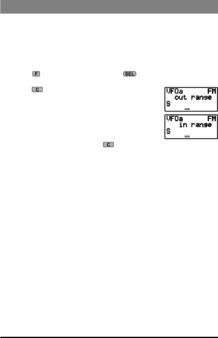
2. Press the (ART) key to activate ARTS™ operation.
3. Your display will change to “out range” to indicate the be-
ginning of ARTS™ operation. Every 25 seconds, your radio
will transmit a “polling” call to the other station. When that
station responds with its return ARTS™ polling signal, your
display will change to “in range” to conrm reception of the
response.
4. To cancel ARTS operation, press the (ART) key again (the “out range” or “in
range” indication will disappear from the LCD).
The ARTS™ feature offers a choice of beep options to alert you to the current status of
ARTS™ operation. Use Menu #09 (ARTS BEEP) on page 59 to select the beep option
that is best for your operating needs.
CW Identier Setup
The ARTS™ feature includes a CW identier. When it is activated, the radio will send “DE
(your callsign) K” in Morse code every ten minutes during ARTS™ operation.
To program the CW IDer, use Menu #31 (ID), as described on page 62. And to activate
the CW IDer, use Menu #18 (CW ID).
36 FT-818 Operating Manual
Transmitter Operation
digital MOde OperatiOn (SSb-baSed aFSk)
The FT-818 provides extensive capability for digital mode operation on the HF, VHF,
and UHF bands. The use of AFSK (Audio Frequency-Shifted Keying) congurations al-
lows a wide variety of different communication modes to be utilized. The Menu provides
for specic digital mode selections, which include custom BFO offsets to optimize the
receive and transmit passbands for the mode selected.
Before beginning Digital operation, you need to dene which Digital mode will be uti-
lized. To do this, use Menu #26 as follows (in this example, we will set up RTTY as the
Digital mode):
1. Press and hold in the key for one second to enter the Menu mode.
2. Rotate the knob to select Menu #26 (DIG MODE).
3. Rotate the knob to select “RTTY.”
4. Press and hold in the key for one second to save the new setting and exit.
Use this technique to set up any digital mode.
RTTY (Radio TeleType) Operation
The “RTTY” mode on the FT-818 is based on LSB-side carrier injection, in accordance
with long-standing amateur practice. If you need USB-side injection for your application,
see the “User” mode discussion below.
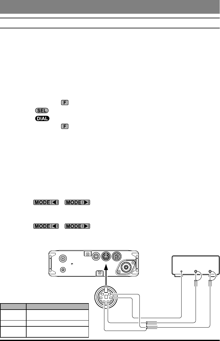
1. Connect your TNC (Terminal Node Controller) or terminal modem to the FT-818’s
rear-panel DATA jack, per the illustration.
2. Press the / key, as needed, to select the DIG mode (the “DIG”
icon will appear on the display). Be certain to use the “TX Audio” line from your
TNC, not an “FSK Key” line, for the transmit-data connection.
3. Press the / key, as needed, to select the DIG mode (the “DIG”
icon will appear on the display). You should now be able to tune around the band, and
any RTTY signals heard should be capable of being decoded.
GND
KEY DATA ACC
ANT
:
INPUT DC13.8V
PTT
DATA IN
GND
AFSK
OUT AF IN
PTT
DATA OUT
Pin Label Note
DATA IN Maximum Input Lebel:
1.0 V pp Impedance: 10 kΩ
PTT Ground to Transmit
DATA OUT Maximum Output Level:
300 mVpp Impedance: 10kΩ
37FT-818 Operating Manual
Transmitter Operation
4. If the optional YF-122C 500 Hz lter has been installed, it may be used for RTTY
work. Recall Operating Function Row 7 [IPO, ATT, NAR] then press the (NAR)
key to engage the narrow lter.
5. To set up the transmit side, be sure that the Meter is set to monitor ALC voltage. If
not, press the key momentarily, then rotate the knob to select to select Op-
erating Function Row 9 [PWR, MTR], then press the (MTR) key so as to select
metering of ALC.
6. Press and hold in the key for 1/2 second to enter the menu mode, then rotate the
knob to select menu #25 (DIG MIC).
7. Following the instructions for your TNC’s software, activate the transmitter from the
computer keyboard; this should cause the AFSK output from the TNC to be sent to the
radio. While transmitting, view the ALC meter; a few “dots” of ALC indication should
be observed. If not, rotate the knob to adjust the AFSK level. Press and hold in
the key for one second to save the new AFSK level setting and return to normal
operation. You are now ready for RTTY operation.
Because RTTY is a continuous-duty transmission mode, try to keep your transmission
short when running on battery power, so as to minimize current drain.
PSK31 Operation
Two dedicated PSK31 modes are available, one each for USB-side and LSB-side injec-
tion. For BPSK work, the injection does not matter, but for QPSK the two working sta-
tions must use the same sideband.
Connect the FT-818 to your computer’s sound card or interface.
Setup for PSK31 operation is basically identical to that previously described for RTTY
operation. As before, use the “DIG” mode. However, in Menu #26, select “PSK31-L” (for
LSB injection) or “PSK31-U” (for USB injection). As with RTTY, Menu #25 may be used
to set the drive to the transmitter. And the YF-122C 500 Hz lter may also be utilized, as
described previously.
38 FT-818 Operating Manual
Transmitter Operation
“USER” Dened Digital Modes
Also provided in the FT-818 are two convenient “USER” Digital modes, one each pro-
viding USB- and LSB-side injection, which may be used for SSTV, Fax, Pactor, and other
digital operating modes.
Here is an example involving the conguration of the USER mode for RTTY with USB-
side injection (as opposed to LSB injection, used in the default “RTTY” mode):
1. Use Menu #26 to set the Digital mode to “USER-U.”
2. Press the / key, as needed, to select the DIG mode (the “DIG”
icon will appear on the display).
3. Now use Menu #27 to configure the transceiver’s passband response. Once in the
Menu mode, rotate the knob to select Menu #27 (DIG SHIFT), and rotate the
knob to set the desired BFO offset (depending on how your TNC’s tones are set
up). For typical high-frequency tone use, a setting of about “+2100” will be a good
starting point.
4. Finally, depending on how you wish the display to respond, you may program in a
corresponding display shift, using Menu #24 (DIG DISP). Remember to press and hold
in the key for one second when exiting the Menu mode.
5. The setup of the AFSK drive level is identical to that described previously for RTTY
operation.
The USER-L and USER-U Digital modes should allow you to operate on any SSB-
based AFSK Digital mode. Note that the “PSK31” congurations will also work well
for many Digital operating situations.
39FT-818 Operating Manual
Transmitter Operation
packet (1200/9600 bpS FM) OperatiOn
The FT-818 is designed for operation on either 1200 bps or 9600 bps packet, and setup
is similar to that described previously for SSB-based modes. A separate Data input ad-
justment is provided, allowing you to optimize the deviation on the FM Packet modes
separately from the SSB-based Digital modes. The RX-Data output lines are xed-level
outputs, not affected by the setting of the AF Gain control.
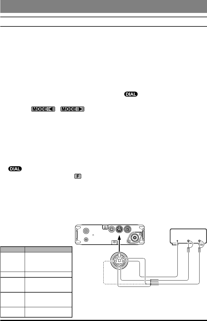
1. Connect your TNC to the FT-818’s rear-panel DATA jack, per the illustration. Note
that different connections are used for 1200 bps and 9600 bps Packet.
2. Use Menu #40 (PKT RATE) to select the desired Packet mode. Once you have entered
the Menu and have selected Menu #40, rotate the knob to select either “1200”
or “9600” (bps) as the Packet rate.
3. Press the / key, as needed, to select the PKT mode (the “PKT”
icon will appear on the display).
4. You are now set up for reception on Packet. If you are operating on 1200 bps, try now
to connect to another station or node; you may well nd that the drive level needs no
further adjustment.
5. If you are having trouble connecting due to insufcient or excessive drive from the
TNC to the FT-818, use Menu #39 (PKT MIC) to set the drive. Use your terminal soft-
ware’s “test” protocol to send out test tones, and adjust the deviation by rotating the
knob, which will vary the data input level to the FT-818’s modulator. Remem-
ber to press and hold in the key for one second when adjustments are completed,
so as to save the new setting for Menu #39.
The 9600 bps Packet deviation setting is very critical to successful operation, and it can
only be accomplished using a calibrated deviation meter; the optimum setting is usually
±2.75 kHz (±0.25 kHz). For 1200 bps, the optimum level is much less critical, with the
optimum deviation being between ±2.5 kHz and ±3.5 kHz.
GND
KEY DATA ACC
ANT
:
INPUT DC13.8V
PTT
DATA IN
GND
DATA
OUT DATA
IN
PTT
DATA OUT
(1200bps)
DATA OUT
(9600bps)
Pin Label Note
DATA IN
Maximum Input Lebel:
40 mV pp @1200 bps
1.0 V pp @9600 bps
Impedance: 10 kΩ
PTT Ground to Transmit
DATA OUT
9600 bps
Maximum Output Level:
500 mVpp
Impedance: 10kΩ
DATA OUT
1200 bps
Maximum Output Level:
300 mVpp
Impedance: 10kΩ
SQL SQL Open: +5 V
SQL Clised: 0 V
40 FT-818 Operating Manual
Transmitter Operation
aM tranSMiSSiOn
The FT-818 utilizes low-level amplitude modulation of an early stage for transmission
purposes. This capability is primarily provided for emergency use only, as low-power op-
eration typically utilizes more efcient transmission/reception modes.
The AM carrier level is preset to 1.5 Watts during alignment at the factory, and should not
require further adjustment. It is important to remember that AM transmission requires that
power must be distributed among the carrier and voice sidebands; therefore, if excessive
carrier power is used, there will be insufcient power available for the information-carry-
ing voice sidebands.
The AM microphone gain is preset at the factory to a value which typically provides good
audio. If you need to modify the microphone gain in the AM mode, use Menu #05 (AM
MIC). See page 58 for details.
Split FreQuencY OperatiOn
This transceiver provides convenient split-frequency operation, using the VFO-A and
VFO-B, for DX working and other operating situations requiring unique split frequency
pairs.
The example below will describe a typical split-frequency DX situation on the 20-meter
band, with a DX station transmitting on 14.025 MHz, listening 10 kHz higher in the band.
1. Set VFO-A to 14.035.00 MHz CW (DX station’s listening frequency).
2. Press the key momentarily, then rotate the knob, as needed, until Operating
Function Row [A/B, A=B, SPL].
3. Press the (A/B) key momentarily to select VFO-B.
4. Tune the VFO-B frequency to 14.025.00 MHz (DX station’s transmitting frequency).
5. Press the (SPL) key momentarily. The transceiver will now transmit using the
VFO-A frequency, and will receive using the VFO-B frequency. The “ ” icon will
appear on the display.
6. To listen to the pile-up calling the DX station (so as to align your frequency more
closely to that of the station being worked by the DX), press the (A/B) key to
reverse the VFOs. You will now be tuning in the vicinity of 14.035 MHz, and you
can zero in on the DX station’s listening frequency by tuning in on the station in QSO
with the DX. Press the (A/B) key again to return to reception on the DX station’s
frequency.
7. Press the (SPL) key once more to cancel split operation; the “ ” icon will dis-
appear from the display.