Yaesu Musen 20335X40 AMATEUR RADIO WITH SCANNING RECEIVER User Manual Cover pmd
Yaesu Musen Co., Ltd. AMATEUR RADIO WITH SCANNING RECEIVER Cover pmd
UserManual.wiki
>
Yaesu Musen
>
20335X40 User Manual
>
Operating Manual 1
Contents
1.
Operating Manual 1
2.
Operating Manual
Operating Manual 1
Navigation menu
Upload a User Manual
Namespaces
Wiki Guide
HTML
PDF
Info
Views
User Manual
Discussion / Help
Navigation
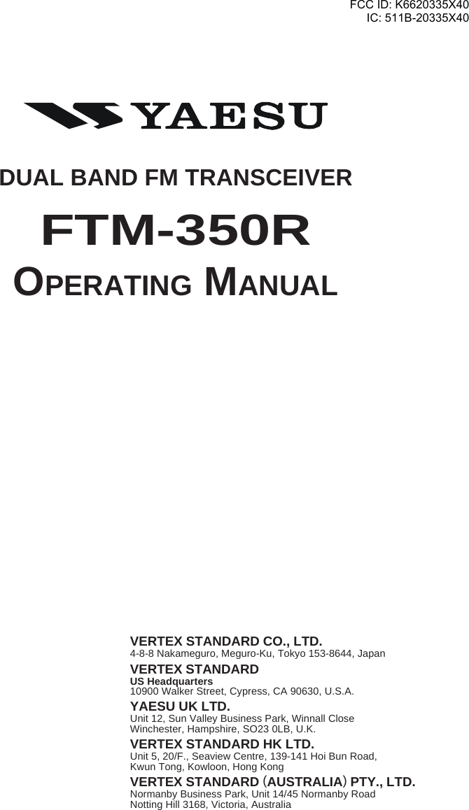
![FTM-350R OPERATING MANUAL 1FRONT PANEL CONTROLS & SWITCHES[PTT] KEYPress this key to transmit.[SET](SET MODE) KEYPress this key to access the Set Mode. [F](FUNCTION) KEYPress this key to change the current functions of the[SMART FUNCTION] keys.[DIAL] KNOBRotate this knob to select the operating frequency(or memory channel) of the right side receiver.Press and hold this knob for one second to enableto tuning the VFO frequency in 1 MHz step.When the right side receiver is set to “Main” band,press this knob briefly to activates the Band Scorpfeature.When the right side receiver is set to “Sub” band,press this knob briefly to change the right sidereceiver to “Main” band.[SMART FUNCTION] KEYThese four keys select many of the most importantoperating features of the transceiver.When changing the operating function page or press-ing the [FUNCTION] key, the current function ofthese key will change and appear above each keys.[DIAL] KNOBRotate this knob to select the operating frequency(or memory channel) of the left side receiver.Press and hold this knob for one second to enableto tuning the VFO frequency in 1 MHz step.When the left side receiver is set to “Main” band,press this knob briefly to activates the Band Scorpfeature.When the leftside receiver is set to “Sub” band,press this knob briefly to change the left side re-ceiver to “Main” band.MICROPHONE[B](BAND) KEYPress this key to change the operating band of theMain band.Available bands are:Left Band: AM Radio, FM Radio, 144 MHz Band,430 MHz Band, and Audio Line-InRight Band: 144 MHz Band and 430 MHz bandYou may assign the other function to this key. Seepage 36.[VOL] KNOBAdjusts the rightside receiver’saudio volume.[VOL] KNOBAdjusts the leftside receiver’saudio volume.[POWER] SWICTHPress and hold this key for two sec-onds to toggle the transceiver’spower on and off.Press this key briefly while thetransceiver is turned on to toggle thekey lockout feature on or off.[FWD]/[BCK](PAGE) KEYPress these keys briefly to select the operating func-tion pages.The available pages are: “Radio” page, “Timer” page,“Baro/Alti” page, “Navigation” page, and “GPSStatus” page.: Requires optional “FGPS-1” GPS Unit.Press and hold in these keys toggle the Dual Receivefeature “on” and “off”.FCC ID: K6620335X40IC: 511B-20335X40](https://usermanual.wiki/Yaesu-Musen/20335X40.Operating-Manual-1/User-Guide-1215303-Page-3.png)
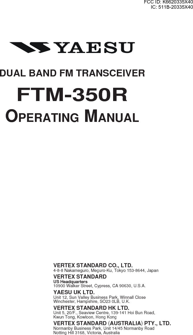
![FTM-350R OPERATING MANUAL2TIMER PAGE OPERATION1Press the [FWD] or [BCK] key repeatedly, until the“Timer Page” appears.2Press the [MODE] key repeatedly, until the “Clock” ap-pears.To return to the “Radio” page, press the [FWD] or [BCK]key repeatedly, until the “Radio” Page appears.The FTM-350’s clock is setup from the Set mode item “I01DATA&TIME ADJUST” in the “TIMER/CLOCK” group.See page 39 for details.21Press the [FWD] or [BCK] key repeatedly, until the“Timer Page” appears.2Press the [MODE] key repeatedly, until the “Count Up”timer appears.The “Count Up” timer has two kinds: which is with Lapfunction and without Lap function.3Press the [SETUP] key to set the interval time of thetimer beep: rotate the [DIAL] knob to select the intervaltime, then press the [SETUP] key.4Press the [START] key to initiate the “Count Up” timer.5Press the [LAP] key to save the lap time, if desired (up tofour laps).6Press the [STOP] key to stop the “Count Up” timer.7Press and hold the [START] key for two seconds to resetthe “Count Up” timer.To return to the “Radio” page, press the [FWD] or [BCK]key repeatedly, until the “Radio” Page appears.2 463 51Press the [FWD] or [BCK] key repeatedly, until the“Timer Page” appears.2Press the [MODE] key repeatedly, until the “CountDown” timer appears.The “Count Down” timer has two kinds: which is withLap function and without Lap function.3Press the [SETUP] key to set the setup time: rotate the[DIAL] knob to select the setup time, then press the[SETUP] key.4Press the [START] key to initiate the “Count Down”timer.5Press the [LAP] key to save the lap time, if desired (up tofour laps).6Press the [STOP] key to stop the “Count Down” timer.7Press and hold the [START] key for two seconds to resetthe “Count Down” timer.To return to the “Radio” page, press the [FWD] or [BCK]key repeatedly, until the “Radio” Page appears.2 4673 5“CLOCK” “COUNT UP” TIMER “COUNT DOWN” TIMER1 1 1FCC ID: K6620335X40IC: 511B-20335X40](https://usermanual.wiki/Yaesu-Musen/20335X40.Operating-Manual-1/User-Guide-1215303-Page-4.png)
![FTM-350R OPERATING MANUAL 3RADIO PAGE BASIC OPERATION1Press and hold the [POWER] key for two seconds to turn the transceiver on.2Rotates the [VOL] knob to adjust the audio volume level.3Adjusts the squelch throshold level: rotates the [DIAL] knob after pressing the [SQL]key.4Press the [DIAL] knob briefly to set the “Main” band.5Press the [B] key to select the operating band of the “Main” band.6Rotate the [DIAL] knob to select the operating frequency.7Speak into the microphone in a normal voice level while pressing the [PTT] key.8Press and hold the [POWER] key for two seconds to turn the transceiver off.3 182 46BASIC OPERATIONYou can do the basic operation in numerical order of the illustration below.6 27MICROPHONE5FCC ID: K6620335X40IC: 511B-20335X40](https://usermanual.wiki/Yaesu-Musen/20335X40.Operating-Manual-1/User-Guide-1215303-Page-5.png)
![FTM-350R OPERATING MANUAL4[SMART FUNCTION] KEYThe radio operation of the FTM-350 performs by changing the [SMART FUNCTION]key into various functions by pushing the [F] key.[SMART FUNCTION] key [FUNCTION] keyThe function command of the [SMART FUNCTION] key replace as follows by pressingthe [F] key. Recall the desired function you want to operate, and perform it.F-1F-1F-1F-1F-1 V/M SQL LOCK REV POWF-2F-2F-2F-2F-2 SCAN DW LOCK SKIP1AF-D2F-1F-1F-1F-1F-1 V/M SQL LOCK REV POWF-2F-2F-2F-2F-2 SCAN DW LOCK SKIP1AF-D2F-3F-3F-3F-3F-3 zREC X CLR LOCK XPLAY VOICEF-1F-1F-1F-1F-1 V/M SQL LOCK REV POWF-2F-2F-2F-2F-2 SCAN DW LOCK SKIP1AF-D2F-3F-3F-3F-3F-3 SyLIST MSG LOCK BCOM B-TXF-4F-4F-4F-4F-4 zREC X CLR LOCK XPLAY VOICESQLSQLSQLSQLSQL TYPE TyFRQ LOCK DyCOD PyFRQDefaultWhen install the optional Voice Guide Unit.When install the optional Voice Guide Unit and GPS Antenna Unit.When press and hold the [F] key for two seconds.1: The [SKIP] command is appeared only in memory mode.2: You may change the [AF-D] command to other command by Set Mode item “G05 F KEY”. Seepage ???.GENERALFCC ID: K6620335X40IC: 511B-20335X40](https://usermanual.wiki/Yaesu-Musen/20335X40.Operating-Manual-1/User-Guide-1215303-Page-6.png)
![FTM-350R OPERATING MANUAL 5[SMART FUNCTION] KEYV/MSQLLOCKREVPOWPress KeyPress & Hold KeyPress KeyPress & Hold KeyPress KeyPress & Hold KeyPress KeyPress & Hold KeyPress KeyPress & Hold KeySwitches frequency control betwenn the “VFO” and “Memory System”.Activates the “Memory Write” mode (for memory channel strage).Activates the Squelch threshold level.No Action.Toggle the key lockout feature “on and “off”.Toggle the transceiver’s power “on and “off”.Reverse transmit and receive frequencies while working through a repeater.No Action.Selects the desired transmit power output level (“LOW”, “MID”, and “HIGH”)No ActionF-1SCANDWLOCKSKIPAF-DPress KeyPress & Hold KeyPress KeyPress & Hold KeyPress KeyPress & Hold KeyPress KeyPress & Hold KeyPress KeyPress & Hold KeyActivates the Scanner.No Action.Activates the Dual Watch feature.No Action.Toggle the key lockout feature “on and “off”.Toggle the transceiver’s power “on and “off”.Selects the “scan flag” to the current memory channel.No Action.Activates the AF Dual function.No Action.F-2SyLISTMSGLOCKBCOMB-TXPress KeyPress & Hold KeyPress KeyPress & Hold KeyPress KeyPress & Hold KeyPress KeyPress & Hold KeyPress KeyPress & Hold KeyInitiates the recording of the incoming receiver audio.No Action.Clears the recording data.No Action.Toggle the key lockout feature “on and “off”.Toggle the transceiver’s power “on and “off”.Play back the recording data.No Action.Announces the operating frequency of the “Main” band.No Action.F-3zRECX CLRLOCKXPLAYVOICEPress KeyPress & Hold KeyPress KeyPress & Hold KeyPress KeyPress & Hold KeyPress KeyPress & Hold KeyPress KeyPress & Hold KeyInitiates the recording of the incoming receiver audio.No Action.Clears the recording data.No Action.Toggle the key lockout feature “on and “off”.Toggle the transceiver’s power “on and “off”.Play back the recording data.Selects the Voice Memory Register (slot 1 - 8, or ALL).Announces the operating frequency of the “Main” band.No Action.F-4[SMART FUNCTION] KEY COMMAND DETAILSTYPETyFRQLOCKDyCODPyFRQPress KeyPress & Hold KeyPress KeyPress & Hold KeyPress KeyPress & Hold KeyPress KeyPress & Hold KeyPress KeyPress & Hold KeySelects the Tone Squelch type.No Action.Selects the CTCSS Tone frequency.No Action.Toggle the key lockout feature “on and “off”.Toggle the transceiver’s power “on and “off”.Selects the DCS code.No Action.Selects the User Programmed Reverse CTCSS Tone frequency..No Action.SQLFCC ID: K6620335X40IC: 511B-20335X40](https://usermanual.wiki/Yaesu-Musen/20335X40.Operating-Manual-1/User-Guide-1215303-Page-7.png)
![FTM-350R OPERATING MANUAL6MEMORY OPERATIONMEMORY STORAGEBefore beginning the Memory Storage operation, select the desired frequncy while operat-ing in the VFO mode by the “Main” band. Be sure to set up any desired CTCSS or DCStones, as well as any desired pereater offset. The power level may also be set at this time, ifyou wish to store it.1Press and hold in the [V/M] key for two seconds to appear the “Memory Edit” window.2If you wish to append an Alpha/numeric “Tag” to this channel, press and hold the[V/M] key again, then enter the desired name “Tag” (up to 8 character) by followingexamples. Otherwise, skip to the next step.Example 1: Press the one of the microphone’s keypad. Press the [A] / [B] key to movethe cursor, and press the [C] key to delete all data after the cursor. Youmay change the character (capital alphabet, small alphabet, numeric, andsymbol) by pressing the [] key.Example 2: Rotate the left side [DIAL] knob to select character/number and press the[] key to move the cursor to the next digit. Press the [BS] key to back-space the cursor. You may change the character (capital alphabet, smallalphabet, numeric, and symbol) by pressing the [FONT] key.3Press the the [V/M] key to store the frequency into memory.1232222Impotant NoteOn rare occasions the memorized data may become corrupted by miss operation,or static electricity. When repairs are made the memory data may be lost. Pleasewrite down or record the memorized information so you will be able to restore it ifneeded.FCC ID: K6620335X40IC: 511B-20335X40](https://usermanual.wiki/Yaesu-Musen/20335X40.Operating-Manual-1/User-Guide-1215303-Page-8.png)
![FTM-350R OPERATING MANUAL 7STORING INDEPENDENT TRANSMIT FREQUNCY (“ODD SPLIT”)All memories can store an independent transmit frequncy, for operation on repeaters withnon-standard shift.Before beginning this procedures, store the receive frequency using the method alreadydescribed on the previous page.1Tune the desired transmit frequncy on the “Main” band, then press and hold in the[V/M] key for two seconds.2Rotate the left side [DIAL] knob to select the same memory channel number as used instep 1 above.3Press the [TXIN] key to store the independent transmit frequncy into memory.12 3MEMORY OPERATIONFCC ID: K6620335X40IC: 511B-20335X40](https://usermanual.wiki/Yaesu-Musen/20335X40.Operating-Manual-1/User-Guide-1215303-Page-9.png)
![FTM-350R OPERATING MANUAL8MEMORY OPERATIONMEMORY RECALL1Press the [V/M] key, the “Main” band becomes to the memory mode.2Rotate the [DIAL] knob to select the select the desired memory channel.3To return to the VFO mode, press the the [V/M] key.When the radio is already set to memory mode, you may recall the memory of the“Main” band by the microphone’s keypad.For example, to recall the memory channel #14, press [0] Æ [1] Æ [4].When recall the “Odd Splits” memory channel, the “ ” indication will appear in thedisplay.When recall the “Tagged” memory channel, displays the memory channel with a Al-pha/numeric “Tag”, and small frequency indication is appeared on the “Tag” indica-tion. You may exchange the relationship between “Tag” indication and “Frequency”indication via Set Mode item “D018 MEMORY DISPLAY” in the “MEMORY” group.132FCC ID: K6620335X40IC: 511B-20335X40](https://usermanual.wiki/Yaesu-Musen/20335X40.Operating-Manual-1/User-Guide-1215303-Page-10.png)
![FTM-350R OPERATING MANUAL 9MEMORY OPERATIONMEMORY EDITYou may edit the memory channel via the Set Mode item “D02 MEMORY EDIIT” in the“MEMORY” group.LABELING MEMORIES1. Rotate the left side [DIAL] knob to select the memory channel on which you wish toappend a label or change a label.2. Press the [V/M] key for two seconds. Append or change a label by the same manner asthe step 2 of the “Memory Storage” procedures (see page 6).COPYING MEMORIES1. Rotate the left side [DIAL] knob to select the memory channel on which you wish tocopy.2. Press the [SEL] key. The selected colum will blink.3. Rotate the left side [DIAL] knob to select the memory channel on which you wish tostore the data.4. Press the [CPY] key to copy the memory channel data.5. Press the [SEL] key to stop the blinking colum.DELETING MEMORIES1. Rotate the left side [DIAL] knob to select the memory channel on which you wish todelete.2. Press the [SEL] key. The selected colum will blink.3. Press the [DEL] key to delete the memory channel data.FCC ID: K6620335X40IC: 511B-20335X40](https://usermanual.wiki/Yaesu-Musen/20335X40.Operating-Manual-1/User-Guide-1215303-Page-11.png)
![FTM-350R OPERATING MANUAL10MEMORY CHANNEL SORTYou may sort and renumber the memory channels by frequency, from low to high via the“Special Function” mode.1. Turn the radio off.2. Turn the radio on while press and holding the key which is located at the left of the[POWER] switch to enter the “Special Function” mode.3. When sort the memory channels in the left band, rotate the left side [DIAL] knob toselect the function menu item “3 L-MEMORY SORT”. When sort the memory chan-nels in the right band, rotate the left side [DIAL] knob to select the function menu item“4 R-MEMORY SORT”.4. Press the left side [DIAL] knob, to display the confirmation message “OK? [SET]” onthe display. If you decide to channel the memory channel sort, press the [ESC] key.5. Press the left side [DIAL] knob again. Several seconds after pressing the left side [DIAL]knob, the FTM-350 is reset automatically and sorting is complete.MEMORY OPERATIONFCC ID: K6620335X40IC: 511B-20335X40](https://usermanual.wiki/Yaesu-Musen/20335X40.Operating-Manual-1/User-Guide-1215303-Page-12.png)
![FTM-350R OPERATING MANUAL 11AF DUAL OPERATIONThe AF Dual function allows you to monitor your desired amateur band frequencies whilelistening to an FM broadcast stations.1Press the [F] key repeatedly, until the [SMART FUNCTION] key’s category replacesto “F-2” mode.2Press the [AD-F] key to activate the AF Dual function.The left side receiver switches to FM Broadcast. You may monitor the right side re-ceiver frequency while receiving the FM Broadcast station.3Rotate the left side [DIAL] knob to tune the desired FM broadcast stations.4If you want to change the audio source to AM Broadcast station or Line-In audio, pressand hold the [AD-F] key for two seconds to access the Set Mode, select the desiredaudio sorce by rorating the left side [DIAL] knob and then press the [ESC] key.5When a signal is received in the amateur band, the amateur band audio is output to thespeaker. The FM or AM broadcast station will no longer be heard.6When the right side receiver is set in the amateur band by “Main” band, you maytransmit on the amateur band by pressing the [PTT] key.7Press the [AD-F] key to disable the AF Dual function and return to normal operation.361247FCC ID: K6620335X40IC: 511B-20335X40](https://usermanual.wiki/Yaesu-Musen/20335X40.Operating-Manual-1/User-Guide-1215303-Page-13.png)
![FTM-350R OPERATING MANUAL12BAND SCOPE OPERATIONGENERALThe Band Scope allows viewing operating activity on channel above or below the currentoperating channel in the VFO mode.1Press the “Main” band’s [DIAL] knob to activate the Band Scope.2Press the [BW] key to toggle the visible bandwidth to “±22 channels” and “±50 chan-nels”.3Press the [ATT] key to reduce the receiving signal to approximately 10 dB, if desired(except the AM and FM Broadcast bands).4Press the [STOP] key to step the sweep of the Band Scope temporily, if desired. Pressthe [START] key to start the sweep of the Band Scope again.5Press the “main” band’s [DIAL] knob to disable the Band Scope and return to normaloperation.21534FCC ID: K6620335X40IC: 511B-20335X40](https://usermanual.wiki/Yaesu-Musen/20335X40.Operating-Manual-1/User-Guide-1215303-Page-14.png)
![FTM-350R OPERATING MANUAL 13BAND SCOPE OPERATIONENHANCED MODEYou may perform the enhanced band scope operation while mono-band operation, whenexpand the function of the Band Scope by the “Special Function” mode.Switching to the Enhanced Mode1. Turn the radio off.2. Turn the radio on while press and holding the key which is located at the left ofthe [POWER] switch to enter the “Special Function” mode.3. Rotate the left side [DIAL] knob to select the function menu item “8 BANDSCOPE”.4. Press the left side [DIAL] knob, then rotate the left side [DIAL] knob to select“SPECIAL”.5. Press the left side [DIAL] knob to save the new setting.6. Press the [ESC] key, the FTM-350R is reset automatically.1Rotate the “Main” band’s [DIAL] knob to tune the operating frequency.2Rotate the “Sub” band’s [DIAL] knob to move the cursor (S).3Press the [C=CSR] key to return the cursor to band center.4Press the [SCSR] key, replace the “S” cursor to “U”. In this case, you may tune theoperating frequency with the cursor together by rotating the “Sub” band’s [DIAL] knob.5Press the [C=CSR] key to return the current frequency and cursor to both band center,and replace the “U” cursor to “S”.14352FCC ID: K6620335X40IC: 511B-20335X40](https://usermanual.wiki/Yaesu-Musen/20335X40.Operating-Manual-1/User-Guide-1215303-Page-15.png)
![FTM-350R OPERATING MANUAL14CTCSS/DCS/EPCS OPERATIONCTCSS OPERATION1. Press and hold in the [F] key for two seconds to replaces the [SMART FUNCTION]key’s category to “SQL”.2. Press the [TYPE] key repeatedly, until the “TONE SQL” notation appears; this acti-vates the CTCSS operation.3. Press the [TyFRQ] key, then rotate the “Main” band’s [DIAL] knob to select the de-sired CTCSS frequency.4. Press the [ESC] key to save the new setting and exit to normal operation.5. To finish the CTCSS operation, press the [TYPE] key repeatedly, until the “OFF”notation appears.You may customize the CTCSS operation so that a ringing “bell” sounds alerts you taht acall is coming in via Set Mode item “J01 BELL RINGER” in the “SIGNALING” group.See page 40 for details.DCS OPERATION1. Press and hold in the [F] key for two seconds to replaces the [SMART FUNCTION]key’s category to “SQL”.2. Press the [TYPE] key repeatedly, until the “DCS” notation appears; this activates theDCS operation.3. Press the [DyCOD] key, then rotate the “Main” band’s [DIAL] knob to select the de-sired DCS code.4. Press the [ESC] key to save the new setting and exit to normal operation.5. To finish the DCS operation, press the [TYPE] key repeatedly, until the “OFF” nota-tion appears.You may customize the DCS operation so that a ringing “bell” sounds alerts you taht a callis coming in via Set Mode item “J01 BELL RINGER” in the “SIGNALING” group. Seepage 40 for details.FCC ID: K6620335X40IC: 511B-20335X40](https://usermanual.wiki/Yaesu-Musen/20335X40.Operating-Manual-1/User-Guide-1215303-Page-16.png)
![FTM-350R OPERATING MANUAL 15CTCSS/DCS/EPCS OPERATIONEPCS OPERATIONThe EPCS (Enhanced Paging & Code Squelch) feature allows you to place a call to aspecific station (Paging), and to receive calls of your choice directed only to you (CodeSquelch).The EPCS feature use two pairs of (alternately switched) CTCSS tones which are stored inthe pager memories. Basically, your receiver remains silent until it receives the CTCSStone pair that matches those stored in the receiving pager memory.1. Store the CTCSS tone pair via Set Mode item “J04 PAGER CODE” in the “SIGNAL-ING” group. Sub menu “1: RX” sets the first tone of the receiving CTCSS tone pair,and the second tone of the receiving CTCSS tone pair is set to Sub menu “2: RX”. In asimilar manner, set the transmitting CTCSS tone pair in the Sub menu “3: RX” and “4:RX”.2. Press and hold in the [F] key for two seconds to replaces the [SMART FUNCTION]key’s category to “SQL”.3. Press the [TYPE] key repeatedly, until the “PAGER” notation appears; this activatesthe EPCS feature.4. To finish the EPCS operation, press the [TYPE] key repeatedly, until the “OFF” nota-tion appears.You may customize the EPCS operation so that a ringing “bell” sounds alerts you taht a callis coming in via Set Mode item “J01 BELL RINGER” in the “SIGNALING” group. Seepage 40 for details.FCC ID: K6620335X40IC: 511B-20335X40](https://usermanual.wiki/Yaesu-Musen/20335X40.Operating-Manual-1/User-Guide-1215303-Page-17.png)
![FTM-350R OPERATING MANUAL16VFO SCAN1. Press the [F] key repeatedly until the [SMART FUNCTION] key’s category replacesto “F-1”, then set the “Main” band to VFO mode by pressing the [V/M] key on the “F-1” category, if necessary.2. Press the [F] key briefly to change the [SMART FUNCTION] key’s category to “F-2”.3. Press the [SCAN] key on the “F-2” category to initiate the VFO scan.3. Press the [SCAN] key again to stop the VFO scan.You may customize the functions of the VFO Scan via following Set Mode items “F02SCAN DIRECTION”, “F03 SCAN RESUME”, “F04 SCAN STOP BEEP” in the“SCAN” group, and “G08 RX COVERAGE” in the “SYSTEM” group.MEMORY SCAN1. Press the [F] key repeatedly until the [SMART FUNCTION] key’s category replacesto “F-1”, then set the “Main” band to memory mode by pressing the [V/M] key on the“F-1” category, if necessary.2. Press the [F] key briefly to change the [SMART FUNCTION] key’s category to “F-2”.3. Press the [SCAN] key on the “F-2” category to initiate the memory scan.4. Press the [SCAN] key again to stop the memory scan.You may customize the functions of the Memory Scan via Set Mode items “D03 MEMORYSCAN TYEP” in the “MEMORY” group, “F04 MEMORY SKIP/SELCT”, “F03 SCANRESUME”, “F04 SCAN STOP BEEP” in the “SCAN” group, and “G08 RX COVER-AGE” in the “SYSTEM” group.SCAN OPERATIONFCC ID: K6620335X40IC: 511B-20335X40](https://usermanual.wiki/Yaesu-Musen/20335X40.Operating-Manual-1/User-Guide-1215303-Page-18.png)