Yaesu Musen 20335X40 AMATEUR RADIO WITH SCANNING RECEIVER User Manual Cover pmd
Yaesu Musen Co., Ltd. AMATEUR RADIO WITH SCANNING RECEIVER Cover pmd
Contents
- 1. Operating Manual 1
- 2. Operating Manual
Operating Manual 1

DUAL BAND FM TRANSCEIVER
FTM-350R
OPERATING MANUAL
VERTEX STANDARD CO., LTD.
4-8-8 Nakameguro, Meguro-Ku, Tokyo 153-8644, Japan
VERTEX STANDARD
US Headquarters
10900 Walker Street, Cypress, CA 90630, U.S.A.
YAESU UK LTD.
Unit 12, Sun Valley Business Park, Winnall Close
Winchester, Hampshire, SO23 0LB, U.K.
VERTEX STANDARD HK LTD.
Unit 5, 20/F., Seaview Centre, 139-141 Hoi Bun Road,
Kwun Tong, Kowloon, Hong Kong
VERTEX STANDARD (AUSTRALIA) PTY., LTD.
Normanby Business Park, Unit 14/45 Normanby Road
Notting Hill 3168, Victoria, Australia
FCC ID: K6620335X40
IC: 511B-20335X40

Contents
FCC ID: K6620335X40
IC: 511B-20335X40
FTM-350R OPERATING MANUAL 1
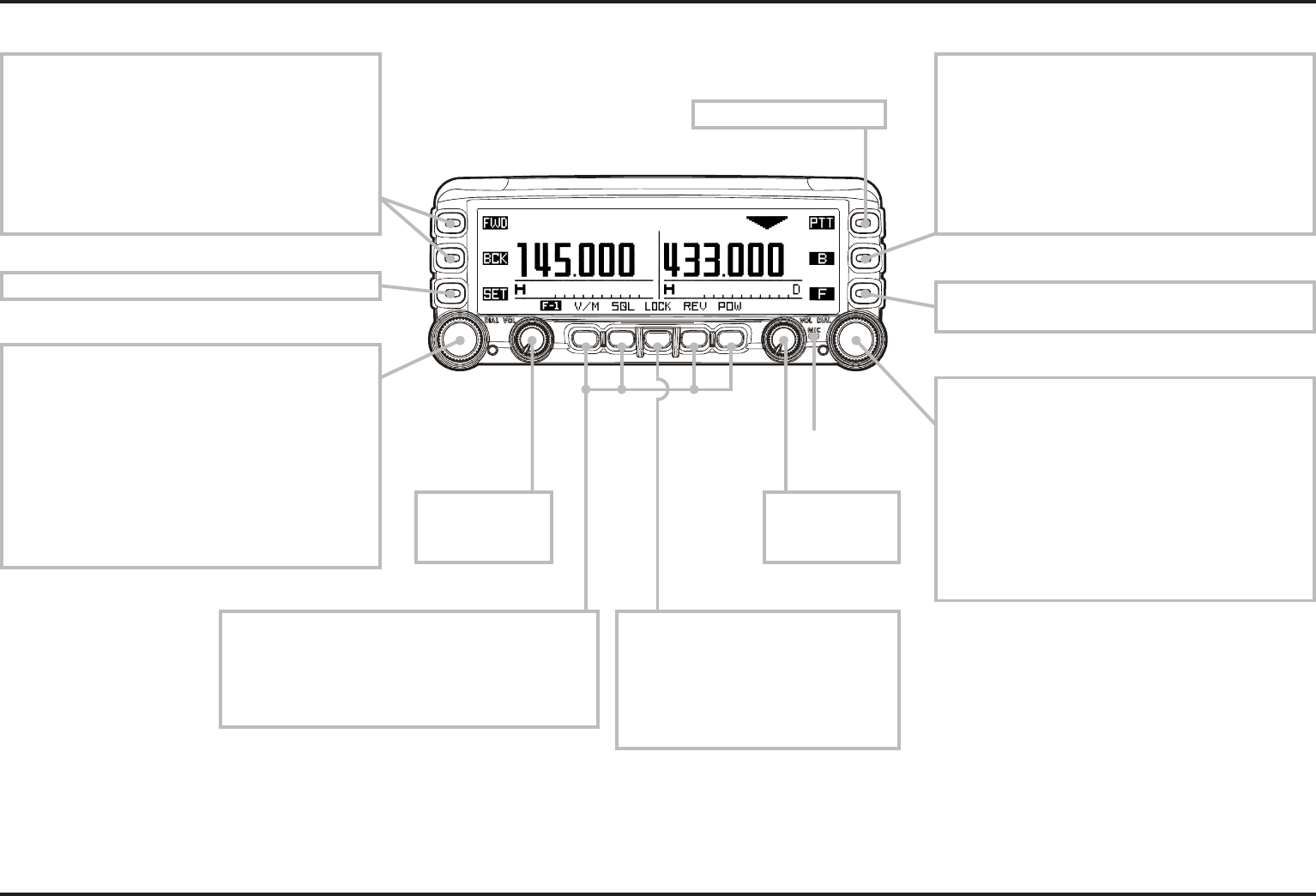
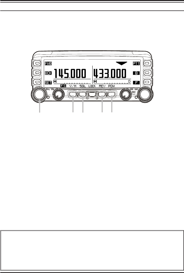
FRONT PANEL CONTROLS & SWITCHES
[PTT] KEY
Press this key to transmit.
[SET](SET MODE) KEY
Press this key to access the Set Mode. [F](FUNCTION) KEY
Press this key to change the current functions of the
[SMART FUNCTION] keys.
[DIAL] KNOB
Rotate this knob to select the operating frequency
(or memory channel) of the right side receiver.
Press and hold this knob for one second to enable
to tuning the VFO frequency in 1 MHz step.
When the right side receiver is set to “Main” band,
press this knob briefly to activates the Band Scorp
feature.
When the right side receiver is set to “Sub” band,
press this knob briefly to change the right side
receiver to “Main” band.
[SMART FUNCTION] KEY
These four keys select many of the most important
operating features of the transceiver.
When changing the operating function page or press-
ing the [FUNCTION] key, the current function of
these key will change and appear above each keys.
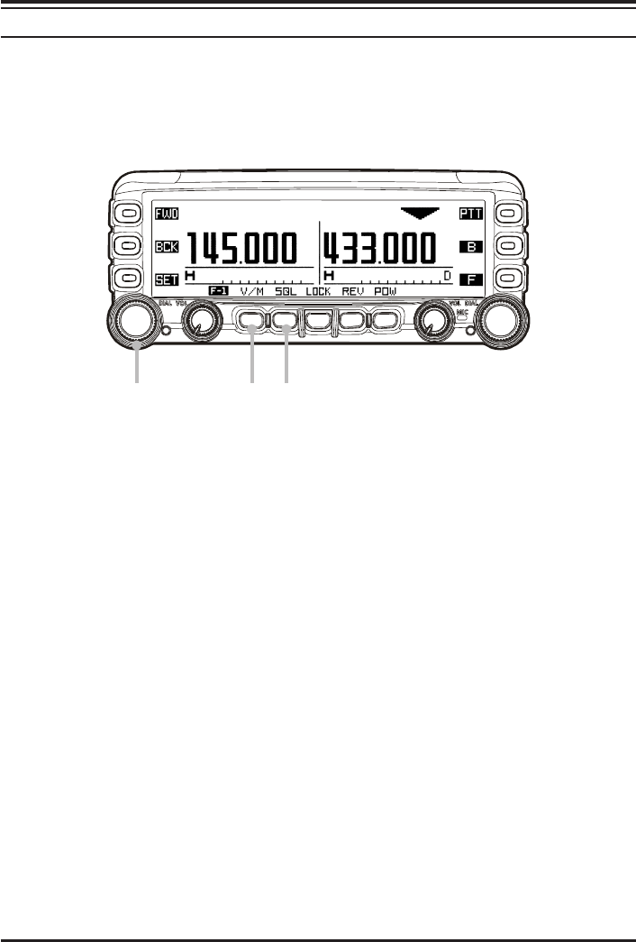
[DIAL] KNOB
Rotate this knob to select the operating frequency
(or memory channel) of the left side receiver.
Press and hold this knob for one second to enable
to tuning the VFO frequency in 1 MHz step.
When the left side receiver is set to “Main” band,
press this knob briefly to activates the Band Scorp
feature.
When the leftside receiver is set to “Sub” band,
press this knob briefly to change the left side re-
ceiver to “Main” band.
MICROPHONE
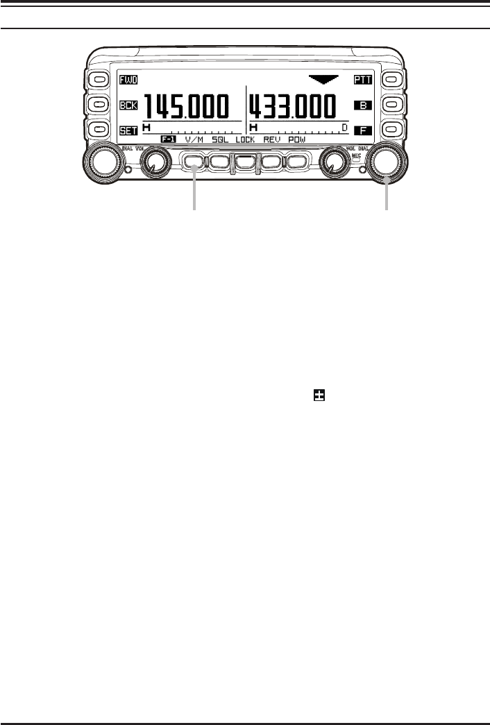
[B](BAND) KEY
Press this key to change the operating band of the
Main band.
Available bands are:
Left Band: AM Radio, FM Radio, 144 MHz Band,
430 MHz Band, and Audio Line-In
Right Band: 144 MHz Band and 430 MHz band
You may assign the other function to this key. See
page 36.
[VOL] KNOB
Adjusts the right
side receiver’s
audio volume.
[VOL] KNOB
Adjusts the left
side receiver’s
audio volume.
[POWER] SWICTH
Press and hold this key for two sec-
onds to toggle the transceiver’s
power on and off.
Press this key briefly while the
transceiver is turned on to toggle the
key lockout feature on or off.
[FWD]/[BCK](PAGE) KEY
Press these keys briefly to select the operating func-
tion pages.
The available pages are: “Radio” page, “Timer” page,
“Baro/Alti” page, “Navigation” page, and “GPS
Status” page.
: Requires optional “FGPS-1” GPS Unit.
Press and hold in these keys toggle the Dual Receive
feature “on” and “off”.
FCC ID: K6620335X40
IC: 511B-20335X40
FTM-350R OPERATING MANUAL2
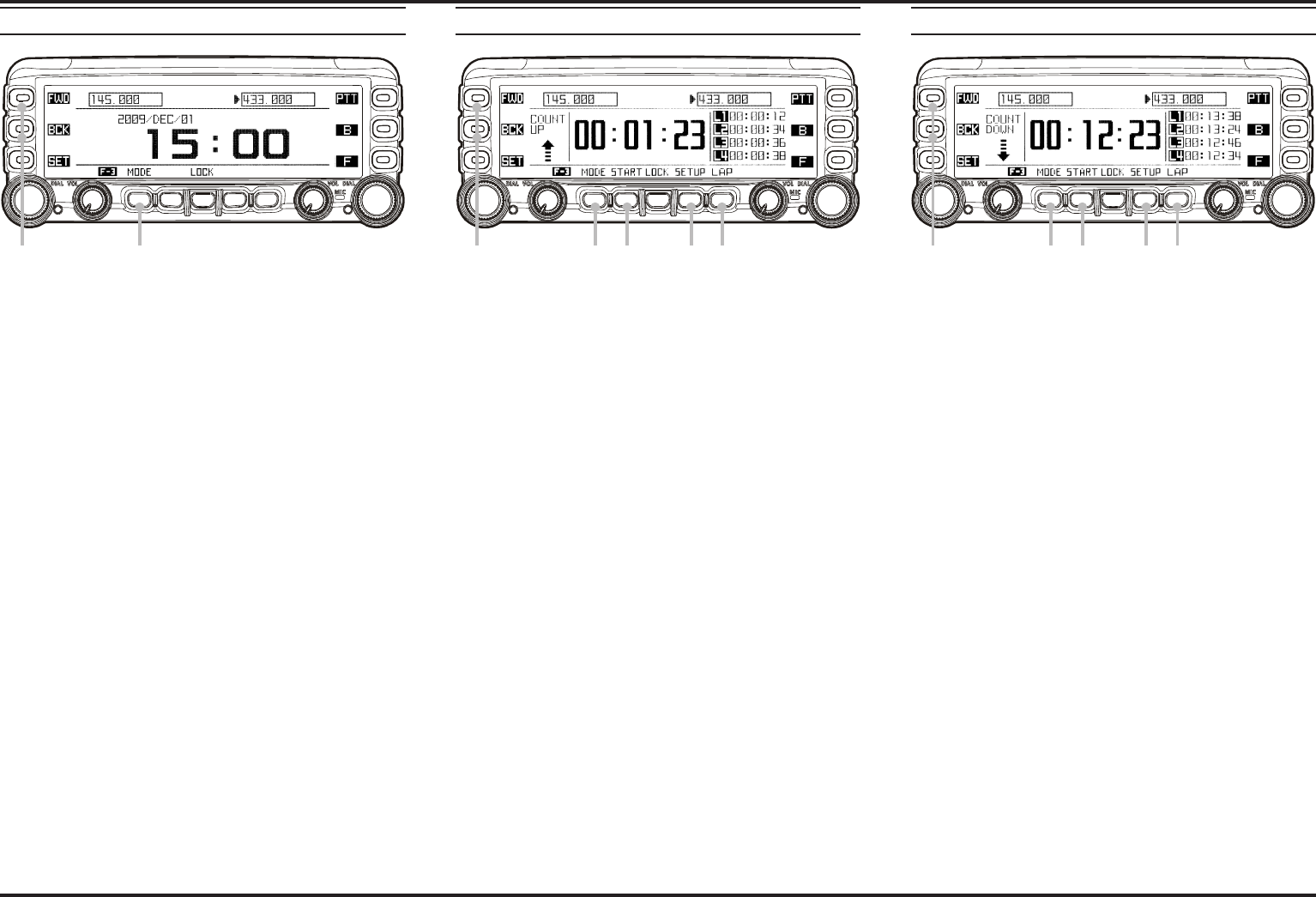
TIMER PAGE OPERATION
1Press the [FWD] or [BCK] key repeatedly, until the
“Timer Page” appears.
2Press the [MODE] key repeatedly, until the “Clock” ap-
pears.
To return to the “Radio” page, press the [FWD] or [BCK]
key repeatedly, until the “Radio” Page appears.
The FTM-350’s clock is setup from the Set mode item “I01
DATA&TIME ADJUST” in the “TIMER/CLOCK” group.
See page 39 for details.
2
1Press the [FWD] or [BCK] key repeatedly, until the
“Timer Page” appears.
2Press the [MODE] key repeatedly, until the “Count Up”
timer appears.
The “Count Up” timer has two kinds: which is with Lap
function and without Lap function.
3Press the [SETUP] key to set the interval time of the
timer beep: rotate the [DIAL] knob to select the interval
time, then press the [SETUP] key.
4Press the [START] key to initiate the “Count Up” timer.
5Press the [LAP] key to save the lap time, if desired (up to
four laps).
6Press the [STOP] key to stop the “Count Up” timer.
7Press and hold the [START] key for two seconds to reset
the “Count Up” timer.
To return to the “Radio” page, press the [FWD] or [BCK]
key repeatedly, until the “Radio” Page appears.
2 4
6
3 5
1Press the [FWD] or [BCK] key repeatedly, until the
“Timer Page” appears.
2Press the [MODE] key repeatedly, until the “Count
Down” timer appears.
The “Count Down” timer has two kinds: which is with
Lap function and without Lap function.
3Press the [SETUP] key to set the setup time: rotate the
[DIAL] knob to select the setup time, then press the
[SETUP] key.
4Press the [START] key to initiate the “Count Down”
timer.
5Press the [LAP] key to save the lap time, if desired (up to
four laps).
6Press the [STOP] key to stop the “Count Down” timer.
7Press and hold the [START] key for two seconds to reset
the “Count Down” timer.
To return to the “Radio” page, press the [FWD] or [BCK]
key repeatedly, until the “Radio” Page appears.
2 4
6
7
3 5
“CLOCK” “COUNT UP” TIMER “COUNT DOWN” TIMER
1 1 1
FCC ID: K6620335X40
IC: 511B-20335X40
FTM-350R OPERATING MANUAL 3
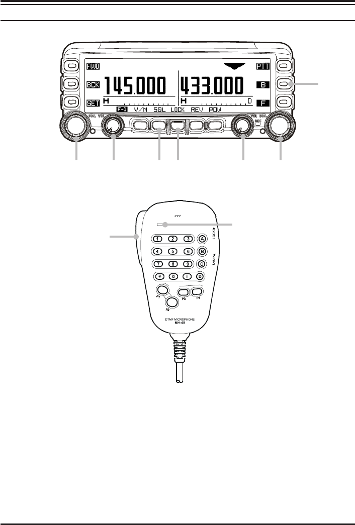
RADIO PAGE BASIC OPERATION
1Press and hold the [POWER] key for two seconds to turn the transceiver on.
2Rotates the [VOL] knob to adjust the audio volume level.
3Adjusts the squelch throshold level: rotates the [DIAL] knob after pressing the [SQL]
key.
4Press the [DIAL] knob briefly to set the “Main” band.
5Press the [B] key to select the operating band of the “Main” band.
6Rotate the [DIAL] knob to select the operating frequency.
7Speak into the microphone in a normal voice level while pressing the [PTT] key.
8Press and hold the [POWER] key for two seconds to turn the transceiver off.
3 1
8
2 4
6
BASIC OPERATION
You can do the basic operation in numerical order of the illustration below.
6 2
7MICROPHONE
5
FCC ID: K6620335X40
IC: 511B-20335X40
FTM-350R OPERATING MANUAL4
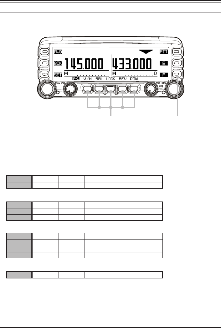
[SMART FUNCTION] KEY
The radio operation of the FTM-350 performs by changing the [SMART FUNCTION]
key into various functions by pushing the [F] key.
[SMART FUNCTION] key [FUNCTION] key
The function command of the [SMART FUNCTION] key replace as follows by pressing
the [F] key. Recall the desired function you want to operate, and perform it.
F-1F-1
F-1F-1
F-1 V/M SQL LOCK REV POW
F-2F-2
F-2F-2
F-2 SCAN DW LOCK SKIP1AF-D2
F-1F-1
F-1F-1
F-1 V/M SQL LOCK REV POW
F-2F-2
F-2F-2
F-2 SCAN DW LOCK SKIP1AF-D2
F-3F-3
F-3F-3
F-3 zREC X CLR LOCK XPLAY VOICE
F-1F-1
F-1F-1
F-1 V/M SQL LOCK REV POW
F-2F-2
F-2F-2
F-2 SCAN DW LOCK SKIP1AF-D2
F-3F-3
F-3F-3
F-3 SyLIST MSG LOCK BCOM B-TX
F-4F-4
F-4F-4
F-4 zREC X CLR LOCK XPLAY VOICE
SQLSQL
SQLSQL
SQL TYPE TyFRQ LOCK DyCOD PyFRQ
Default
When install the optional Voice Guide Unit.
When install the optional Voice Guide Unit and GPS Antenna Unit.
When press and hold the [F] key for two seconds.
1: The [SKIP] command is appeared only in memory mode.
2: You may change the [AF-D] command to other command by Set Mode item “G05 F KEY”. See
page ???.
GENERAL
FCC ID: K6620335X40
IC: 511B-20335X40

FTM-350R OPERATING MANUAL 5
[SMART FUNCTION] KEY
V/M
SQL
LOCK
REV
POW
Press Key
Press & Hold Key
Press Key
Press & Hold Key
Press Key
Press & Hold Key
Press Key
Press & Hold Key
Press Key
Press & Hold Key
Switches frequency control betwenn the “VFO” and “Memory System”.
Activates the “Memory Write” mode (for memory channel strage).
Activates the Squelch threshold level.
No Action.
Toggle the key lockout feature “on and “off”.
Toggle the transceiver’s power “on and “off”.
Reverse transmit and receive frequencies while working through a repeater.
No Action.
Selects the desired transmit power output level (“LOW”, “MID”, and “HIGH”)
No Action
F-1
SCAN
DW
LOCK
SKIP
AF-D
Press Key
Press & Hold Key
Press Key
Press & Hold Key
Press Key
Press & Hold Key
Press Key
Press & Hold Key
Press Key
Press & Hold Key
Activates the Scanner.
No Action.
Activates the Dual Watch feature.
No Action.
Toggle the key lockout feature “on and “off”.
Toggle the transceiver’s power “on and “off”.
Selects the “scan flag” to the current memory channel.
No Action.
Activates the AF Dual function.
No Action.
F-2
SyLIST
MSG
LOCK
BCOM
B-TX
Press Key
Press & Hold Key
Press Key
Press & Hold Key
Press Key
Press & Hold Key
Press Key
Press & Hold Key
Press Key
Press & Hold Key
Initiates the recording of the incoming receiver audio.
No Action.
Clears the recording data.
No Action.
Toggle the key lockout feature “on and “off”.
Toggle the transceiver’s power “on and “off”.
Play back the recording data.
No Action.
Announces the operating frequency of the “Main” band.
No Action.
F-3
zREC
X CLR
LOCK
XPLAY
VOICE
Press Key
Press & Hold Key
Press Key
Press & Hold Key
Press Key
Press & Hold Key
Press Key
Press & Hold Key
Press Key
Press & Hold Key
Initiates the recording of the incoming receiver audio.
No Action.
Clears the recording data.
No Action.
Toggle the key lockout feature “on and “off”.
Toggle the transceiver’s power “on and “off”.
Play back the recording data.
Selects the Voice Memory Register (slot 1 - 8, or ALL).
Announces the operating frequency of the “Main” band.
No Action.
F-4
[SMART FUNCTION] KEY COMMAND DETAILS
TYPE
TyFRQ
LOCK
DyCOD
PyFRQ
Press Key
Press & Hold Key
Press Key
Press & Hold Key
Press Key
Press & Hold Key
Press Key
Press & Hold Key
Press Key
Press & Hold Key
Selects the Tone Squelch type.
No Action.
Selects the CTCSS Tone frequency.
No Action.
Toggle the key lockout feature “on and “off”.
Toggle the transceiver’s power “on and “off”.
Selects the DCS code.
No Action.
Selects the User Programmed Reverse CTCSS Tone frequency..
No Action.
SQL
FCC ID: K6620335X40
IC: 511B-20335X40
FTM-350R OPERATING MANUAL6
MEMORY OPERATION
MEMORY STORAGE
Before beginning the Memory Storage operation, select the desired frequncy while operat-
ing in the VFO mode by the “Main” band. Be sure to set up any desired CTCSS or DCS
tones, as well as any desired pereater offset. The power level may also be set at this time, if
you wish to store it.
1Press and hold in the [V/M] key for two seconds to appear the “Memory Edit” window.
2If you wish to append an Alpha/numeric “Tag” to this channel, press and hold the
[V/M] key again, then enter the desired name “Tag” (up to 8 character) by following
examples. Otherwise, skip to the next step.
Example 1: Press the one of the microphone’s keypad. Press the [A] / [B] key to move
the cursor, and press the [C] key to delete all data after the cursor. You
may change the character (capital alphabet, small alphabet, numeric, and
symbol) by pressing the [] key.
Example 2: Rotate the left side [DIAL] knob to select character/number and press the
[] key to move the cursor to the next digit. Press the [BS] key to back-
space the cursor. You may change the character (capital alphabet, small
alphabet, numeric, and symbol) by pressing the [FONT] key.
3Press the the [V/M] key to store the frequency into memory.
1
2
3
2
222
Impotant Note
On rare occasions the memorized data may become corrupted by miss operation,
or static electricity. When repairs are made the memory data may be lost. Please
write down or record the memorized information so you will be able to restore it if
needed.
FCC ID: K6620335X40
IC: 511B-20335X40
FTM-350R OPERATING MANUAL 7
STORING INDEPENDENT TRANSMIT FREQUNCY (“ODD SPLIT”)
All memories can store an independent transmit frequncy, for operation on repeaters with
non-standard shift.
Before beginning this procedures, store the receive frequency using the method already
described on the previous page.
1Tune the desired transmit frequncy on the “Main” band, then press and hold in the
[V/M] key for two seconds.
2Rotate the left side [DIAL] knob to select the same memory channel number as used in
step 1 above.
3Press the [TXIN] key to store the independent transmit frequncy into memory.
12 3
MEMORY OPERATION
FCC ID: K6620335X40
IC: 511B-20335X40
FTM-350R OPERATING MANUAL8
MEMORY OPERATION
MEMORY RECALL
1Press the [V/M] key, the “Main” band becomes to the memory mode.
2Rotate the [DIAL] knob to select the select the desired memory channel.
3To return to the VFO mode, press the the [V/M] key.
When the radio is already set to memory mode, you may recall the memory of the
“Main” band by the microphone’s keypad.
For example, to recall the memory channel #14, press [0] Æ [1] Æ [4].
When recall the “Odd Splits” memory channel, the “ ” indication will appear in the
display.
When recall the “Tagged” memory channel, displays the memory channel with a Al-
pha/numeric “Tag”, and small frequency indication is appeared on the “Tag” indica-
tion. You may exchange the relationship between “Tag” indication and “Frequency”
indication via Set Mode item “D018 MEMORY DISPLAY” in the “MEMORY” group.
1
3
2
FCC ID: K6620335X40
IC: 511B-20335X40

FTM-350R OPERATING MANUAL 9
MEMORY OPERATION
MEMORY EDIT
You may edit the memory channel via the Set Mode item “D02 MEMORY EDIIT” in the
“MEMORY” group.
LABELING MEMORIES
1. Rotate the left side [DIAL] knob to select the memory channel on which you wish to
append a label or change a label.
2. Press the [V/M] key for two seconds. Append or change a label by the same manner as
the step 2 of the “Memory Storage” procedures (see page 6).
COPYING MEMORIES
1. Rotate the left side [DIAL] knob to select the memory channel on which you wish to
copy.
2. Press the [SEL] key. The selected colum will blink.
3. Rotate the left side [DIAL] knob to select the memory channel on which you wish to
store the data.
4. Press the [CPY] key to copy the memory channel data.
5. Press the [SEL] key to stop the blinking colum.
DELETING MEMORIES
1. Rotate the left side [DIAL] knob to select the memory channel on which you wish to
delete.
2. Press the [SEL] key. The selected colum will blink.
3. Press the [DEL] key to delete the memory channel data.
FCC ID: K6620335X40
IC: 511B-20335X40

FTM-350R OPERATING MANUAL10
MEMORY CHANNEL SORT
You may sort and renumber the memory channels by frequency, from low to high via the
“Special Function” mode.
1. Turn the radio off.
2. Turn the radio on while press and holding the key which is located at the left of the
[POWER] switch to enter the “Special Function” mode.
3. When sort the memory channels in the left band, rotate the left side [DIAL] knob to
select the function menu item “3 L-MEMORY SORT”. When sort the memory chan-
nels in the right band, rotate the left side [DIAL] knob to select the function menu item
“4 R-MEMORY SORT”.
4. Press the left side [DIAL] knob, to display the confirmation message “OK? [SET]” on
the display. If you decide to channel the memory channel sort, press the [ESC] key.
5. Press the left side [DIAL] knob again. Several seconds after pressing the left side [DIAL]
knob, the FTM-350 is reset automatically and sorting is complete.
MEMORY OPERATION
FCC ID: K6620335X40
IC: 511B-20335X40

FTM-350R OPERATING MANUAL 11
AF DUAL OPERATION
The AF Dual function allows you to monitor your desired amateur band frequencies while
listening to an FM broadcast stations.
1Press the [F] key repeatedly, until the [SMART FUNCTION] key’s category replaces
to “F-2” mode.
2Press the [AD-F] key to activate the AF Dual function.
The left side receiver switches to FM Broadcast. You may monitor the right side re-
ceiver frequency while receiving the FM Broadcast station.
3Rotate the left side [DIAL] knob to tune the desired FM broadcast stations.
4If you want to change the audio source to AM Broadcast station or Line-In audio, press
and hold the [AD-F] key for two seconds to access the Set Mode, select the desired
audio sorce by rorating the left side [DIAL] knob and then press the [ESC] key.
5When a signal is received in the amateur band, the amateur band audio is output to the
speaker. The FM or AM broadcast station will no longer be heard.
6When the right side receiver is set in the amateur band by “Main” band, you may
transmit on the amateur band by pressing the [PTT] key.
7Press the [AD-F] key to disable the AF Dual function and return to normal operation.
3
6
1
2
4
7
FCC ID: K6620335X40
IC: 511B-20335X40

FTM-350R OPERATING MANUAL12
BAND SCOPE OPERATION
GENERAL
The Band Scope allows viewing operating activity on channel above or below the current
operating channel in the VFO mode.
1Press the “Main” band’s [DIAL] knob to activate the Band Scope.
2Press the [BW] key to toggle the visible bandwidth to “±22 channels” and “±50 chan-
nels”.
3Press the [ATT] key to reduce the receiving signal to approximately 10 dB, if desired
(except the AM and FM Broadcast bands).
4Press the [STOP] key to step the sweep of the Band Scope temporily, if desired. Press
the [START] key to start the sweep of the Band Scope again.
5Press the “main” band’s [DIAL] knob to disable the Band Scope and return to normal
operation.
21
5
34
FCC ID: K6620335X40
IC: 511B-20335X40
FTM-350R OPERATING MANUAL 13
BAND SCOPE OPERATION
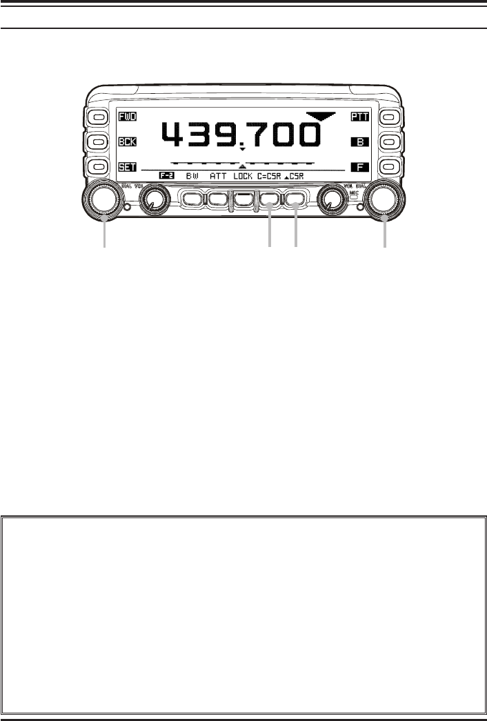
ENHANCED MODE
You may perform the enhanced band scope operation while mono-band operation, when
expand the function of the Band Scope by the “Special Function” mode.
Switching to the Enhanced Mode
1. Turn the radio off.
2. Turn the radio on while press and holding the key which is located at the left of
the [POWER] switch to enter the “Special Function” mode.
3. Rotate the left side [DIAL] knob to select the function menu item “8 BAND
SCOPE”.
4. Press the left side [DIAL] knob, then rotate the left side [DIAL] knob to select
“SPECIAL”.
5. Press the left side [DIAL] knob to save the new setting.
6. Press the [ESC] key, the FTM-350R is reset automatically.
1Rotate the “Main” band’s [DIAL] knob to tune the operating frequency.
2Rotate the “Sub” band’s [DIAL] knob to move the cursor (S).
3Press the [C=CSR] key to return the cursor to band center.
4Press the [SCSR] key, replace the “S” cursor to “U”. In this case, you may tune the
operating frequency with the cursor together by rotating the “Sub” band’s [DIAL] knob.
5Press the [C=CSR] key to return the current frequency and cursor to both band center,
and replace the “U” cursor to “S”.
1
4
3
5
2
FCC ID: K6620335X40
IC: 511B-20335X40

FTM-350R OPERATING MANUAL14
CTCSS/DCS/EPCS OPERATION
CTCSS OPERATION
1. Press and hold in the [F] key for two seconds to replaces the [SMART FUNCTION]
key’s category to “SQL”.
2. Press the [TYPE] key repeatedly, until the “TONE SQL” notation appears; this acti-
vates the CTCSS operation.
3. Press the [TyFRQ] key, then rotate the “Main” band’s [DIAL] knob to select the de-
sired CTCSS frequency.
4. Press the [ESC] key to save the new setting and exit to normal operation.
5. To finish the CTCSS operation, press the [TYPE] key repeatedly, until the “OFF”
notation appears.
You may customize the CTCSS operation so that a ringing “bell” sounds alerts you taht a
call is coming in via Set Mode item “J01 BELL RINGER” in the “SIGNALING” group.
See page 40 for details.
DCS OPERATION
1. Press and hold in the [F] key for two seconds to replaces the [SMART FUNCTION]
key’s category to “SQL”.
2. Press the [TYPE] key repeatedly, until the “DCS” notation appears; this activates the
DCS operation.
3. Press the [DyCOD] key, then rotate the “Main” band’s [DIAL] knob to select the de-
sired DCS code.
4. Press the [ESC] key to save the new setting and exit to normal operation.
5. To finish the DCS operation, press the [TYPE] key repeatedly, until the “OFF” nota-
tion appears.
You may customize the DCS operation so that a ringing “bell” sounds alerts you taht a call
is coming in via Set Mode item “J01 BELL RINGER” in the “SIGNALING” group. See
page 40 for details.
FCC ID: K6620335X40
IC: 511B-20335X40

FTM-350R OPERATING MANUAL 15
CTCSS/DCS/EPCS OPERATION
EPCS OPERATION
The EPCS (Enhanced Paging & Code Squelch) feature allows you to place a call to a
specific station (Paging), and to receive calls of your choice directed only to you (Code
Squelch).
The EPCS feature use two pairs of (alternately switched) CTCSS tones which are stored in
the pager memories. Basically, your receiver remains silent until it receives the CTCSS
tone pair that matches those stored in the receiving pager memory.
1. Store the CTCSS tone pair via Set Mode item “J04 PAGER CODE” in the “SIGNAL-
ING” group. Sub menu “1: RX” sets the first tone of the receiving CTCSS tone pair,
and the second tone of the receiving CTCSS tone pair is set to Sub menu “2: RX”. In a
similar manner, set the transmitting CTCSS tone pair in the Sub menu “3: RX” and “4:
RX”.
2. Press and hold in the [F] key for two seconds to replaces the [SMART FUNCTION]
key’s category to “SQL”.
3. Press the [TYPE] key repeatedly, until the “PAGER” notation appears; this activates
the EPCS feature.
4. To finish the EPCS operation, press the [TYPE] key repeatedly, until the “OFF” nota-
tion appears.
You may customize the EPCS operation so that a ringing “bell” sounds alerts you taht a call
is coming in via Set Mode item “J01 BELL RINGER” in the “SIGNALING” group. See
page 40 for details.
FCC ID: K6620335X40
IC: 511B-20335X40

FTM-350R OPERATING MANUAL16
VFO SCAN
1. Press the [F] key repeatedly until the [SMART FUNCTION] key’s category replaces
to “F-1”, then set the “Main” band to VFO mode by pressing the [V/M] key on the “F-
1” category, if necessary.
2. Press the [F] key briefly to change the [SMART FUNCTION] key’s category to “F-
2”.
3. Press the [SCAN] key on the “F-2” category to initiate the VFO scan.
3. Press the [SCAN] key again to stop the VFO scan.
You may customize the functions of the VFO Scan via following Set Mode items “F02
SCAN DIRECTION”, “F03 SCAN RESUME”, “F04 SCAN STOP BEEP” in the
“SCAN” group, and “G08 RX COVERAGE” in the “SYSTEM” group.
MEMORY SCAN
1. Press the [F] key repeatedly until the [SMART FUNCTION] key’s category replaces
to “F-1”, then set the “Main” band to memory mode by pressing the [V/M] key on the
“F-1” category, if necessary.
2. Press the [F] key briefly to change the [SMART FUNCTION] key’s category to “F-
2”.
3. Press the [SCAN] key on the “F-2” category to initiate the memory scan.
4. Press the [SCAN] key again to stop the memory scan.
You may customize the functions of the Memory Scan via Set Mode items “D03 MEMORY
SCAN TYEP” in the “MEMORY” group, “F04 MEMORY SKIP/SELCT”, “F03 SCAN
RESUME”, “F04 SCAN STOP BEEP” in the “SCAN” group, and “G08 RX COVER-
AGE” in the “SYSTEM” group.
SCAN OPERATION
FCC ID: K6620335X40
IC: 511B-20335X40