Yaesu Musen 20335X40 AMATEUR RADIO WITH SCANNING RECEIVER User Manual Cover pmd
Yaesu Musen Co., Ltd. AMATEUR RADIO WITH SCANNING RECEIVER Cover pmd
Contents
- 1. Operating Manual 1
- 2. Operating Manual
Operating Manual

FTM-350R OPERATING MANUAL 17
PROGRAMMABLE MEMORY SCAN (PMS)
This feature allows you to scan on the sub-band limits.
1. Store the lower sub-band limits into the memory channel “P1L”.
2. Store the upper sub-band limits into the memory channel “P1U”.
3. Set the “Main” band to memory mode by pressing the [V/M] key on the “F-1” cat-
egory, if necessary.
4. Recall the memory channel “P1L” or “P1U”.
5. Press the [F] key briefly to change the [SMART FUNCTION] key’s category to “F-
2”.
6. Press the [SCAN] key on the “F-2” category to initiate the scanner within the pro-
grammed range.
7. Press the [SCAN] key again to stop the scanner.
8. Press the [V/M] key on the “F-1” category to change the memory mode, then press the
[V/M] key again to change the VFO mode.
9. Nine pairs of band limit memories, labeled “P1L/P1U” through “P9L/P9U” available.
You therefore can set lower and upper operation limits on a number of bands, if you
like.
You may customize the functions of the Memory Scan via Set Mode items “D03 MEMORY
SCAN TYEP” in the “MEMORY” group, “F04 MEMORY SKIP/SELCT”, “F03 SCAN
RESUME”, “F04 SCAN STOP BEEP” in the “SCAN” group, and “G08 RX COVER-
AGE” in the “SYSTEM” group.
PRIORITY CHANNEL SCAN (DUAL WATCH)
This feature is a two-channel scanning capability which allows you to operate on a VFO or
Memory channel, while periodically checking a “Priority” memory channel “000” for ac-
tivity.
1. Store the frequency which you wish to check periodic into the “Priority” memory channel
“PRM”.
2. Press the [F] key repeatedly until the [SMART FUNCTION] key’s category replaces
to “F-2”.
3. Press the [DW] key on the “F-2” category to initiate the Dual Watch feature.
4. Press the [SCAN] key again to stop the Dual Watch feature.
You may customize the functions of the Dual Watch feature via Set Mode items “F01
DUAL WATCH STOP” and “F03 SCAN RESUME” in the “SCAN” group.
SCAN OPERATION
FCC ID: K6620335X40
IC: 511B-20335X40

FTM-350R OPERATING MANUAL18
BLUETOOTH® OPERATION
When install the optional BU-1 Bluetooth® Unit, the FTM-350R to send/receive voice
message with the optional BH-1A or BH-2A Bluetooth® Headset via wireless links.
PAIRING
1. Turn the radio and Bluetooth® Headset both off.
2. Turn the radio on while press and holding the key which is located at the left of the
[POWER] switch to enter the “Special Function” mode.
3. Rotate the left side [DIAL] knob to select the function menu item “9 B-T PAIRING”.
4. Press the left side [DIAL] knob.
5. Press and hold the power switch on the Bluetooth® Headset for five seconds, until the
Bluetooth® Headset’s indicator blinks red/blue alternately.
6. Press the left side [DIAL] knob to initiate the pairing.
7. If the pairing is successful (requires a 20 to 30 seconds), “PAIRING OK !” notation
will appear on the display. The FTM-350R will turn off and back on again.
When the Bluetooth® Headset is correctly recognized by the FTM-350, the
Bluetooth® Headset’s indicator will blink blue.
8. Set up the various function of the Bluetooth® via Set Mode items “K01
BLUETOOTH”.
FCC ID: K6620335X40
IC: 511B-20335X40

FTM-350R OPERATING MANUAL 19
BLUETOOTH® OPERATION
OPERATION
1. When the Bluetooth® Headset is correctly recognized by the FTM-350R, “ ” icon
will appear on the display of the FTM-350R and the LED indicator of the Bluetooth®
Headset will blink blue.
2. Adjust the receiver audio level using the [VOLUME(+)]/[VOLUME(–)] switches on
the Bluetooth® Headset.
3. Press the PTT switch on the Bluetooth® Headset to transmit. Release the PTT switch
to return to receive.
4. If your Bluetooth® Headset is BH-2A, you may adjust the microphone gain (Five
steps) of the BH-2A by pressing the [VOLUME(+)]/[VOLUME(–)] switch while press-
ing and holding the PTT switch, if desired.
5. The communication range between the Bluetooth® Headset and FTM-350 is around
1 m (3 ft). If you move out of range, a beep will be heard from the Bluetooth® Head-
set to alert you. If you move back into range, the Bluetooth® Headset will beep to
alert you that you are back within range.
6. When the battery voltage of the Bluetooth® Headset is low;
a. the LED on the Bluetooth® Headset will blink Red and Blue.
b. a beep will be heard from the Bluetooth® Headset.
c. the “ ” icon on the FTM-350R will be blinking fast.
Charge the battery of the Bluetooth® Headset.
In the factory default, the FTM-350R’s internal and external speakers are disabled when
the Bluetooth® Headset is correctly recognized. Additionally, the microphones which lo-
cated on the front panel and connected to the front panel MIC jack are also disabled when
the Bluetooth® Headset is correctly recognized. However, the microphone which con-
nected to the transceiver’s MIC jack is alive.
You may customize the Bluetooth® operation via Set Mode items “K01 BLUETOOTH”
in the “OPTION” group. See page 42.
FCC ID: K6620335X40
IC: 511B-20335X40

FTM-350R OPERATING MANUAL20
INTERNET CONNECTION FEATURE
The FTM-350R can be used to access a “node” (repeater or base station) which is tied into
the Vertex Standard WiRES™ (Wide-Coverage Internet Repeater Enhancement System)
network, operating in the “SRG” (Sister Radio Group) mode. Details may be found at the
WiRES-II Web site: http://www.vxstd.com/en/wiresinfo-en/.
SRG (“SISTER RADIO GROUP”) MODE
1. Sets the Set Mode item “J06 WiRES” in the “SIGNALING” group to “SRG”. See
page 41.
2. Selects the access number corresponding to the WiRES™ repeater via Set Mode item
“J07 WiRES MEMORY” in the “SIGNALING” group. See page 41.
3. When exit from the Set Mode, activate the Internet Connection feature in the “SRG”
mode.
4. With the Internet Connection feature activated, the FTM-350R will generate a brief
(0.1 sec) DTMF tone according to your selection in step 2. This DTMF tone is sent at
the beginning of every transmission to establish or maintain the link to the remote
WIRES™ repeater operating in the “SRG” mode.
4. To disable the Internet Connection feature, select the “OFF” selection in the Set Mode
item “J06 WiRES”.
FCC ID: K6620335X40
IC: 511B-20335X40

FTM-350R OPERATING MANUAL 21
INTERNET CONNECTION FEATURE
FRG (“FRIENDLY RADIO GROUP”) MODE
1. Store the access code of the Internet link to the DTMF memory register via Set Mode
item “J02 DTMF MEMORY” in the “SIGNALING” group. See page 40.
2. Sets the Set Mode item “J06 WiRES” in the “SIGNALING” group to “FRG”. See
page 41.
3. When exit from the Set Mode, activate the Internet Connection feature in the “FRG”
mode.
4. To access the FRG node, perform the following procedures while pressing the PTT
switch:
1) Press the [WiRES] key (located at the left edge of the [SMART FUNCTION] key
while transmitting).
2) Rotate the [DIAL] knob to select the DTMF memory register corresponding to the
WiRES™ repeater you wish to establish an internet link.
3) Press the [WiRES] key again to transmit the access code.
5. To disable the Internet Connection feature, select the “OFF” selection in the Set Mode
item “J06 WiRES”.
FCC ID: K6620335X40
IC: 511B-20335X40

FTM-350R OPERATING MANUAL22
DTMF OPERATION
MANUAL DTMF TONE GENERATION
1. Press the microphone’s PTT switch to begin transmission.
2. While transmitting, press the desired numbers key on the microphone.
3. When you have sent all the digits desired, release the PTT switch.
DTMF AUTODIALER
1. Store the telephone number to the DTMF memory register via Set Mode item “J02
DTMF MEMORY” in the “SIGNALING” group. See page 40.
2. Sets the Set Mode item “J03 DTMF MODE” in the “SIGNALING” group to “ON”.
See page 40.
3. When exit from the Set Mode, activate the DTMF Autodialer.
4. To send the telephone number, perform the following procedures while pressing the
PTT switch:
1) Press the [DTMF] key (located at the left side of the [POWER] key while trans-
mitting).
2) Rotate the [DIAL] knob to select the DTMF memory register corresponding to the
telephone number you wish to send.
3) Press the [DTMF] key again to transmit the telephone number.
5. To disable the DTMF Autodialer, select the “OFF” selection in the Set Mode item “J06
DTMF MODE”.
You may send the telephone number by pressing the microphone’s numeric key ([1] through
[9]) corresponding to the DTMF memory string you wish to send.
FCC ID: K6620335X40
IC: 511B-20335X40
FTM-350R OPERATING MANUAL 23
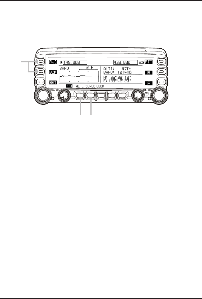
BARO/ALTI PAGE
The FTM-350R can display the current Barometric Pressure and relative changes in the
pressure. Furthermore, if you install the optional FGPS-1 or FGPS-2 GPS Unit, the
FTM-350R can display the current altitude and relative changes in the altitude.
To display the “Baro/Alti” Page, enablesthe “BARO/ALTI” page via Set Mode item “C01
DISPLAY SELECT” in the “DISPLAY” group, beforehand. See page 33.
1Press the [FWD] or [BCK] key repeatedly, until the “Baro/Alti” Page appears.
The current Barometric Pressure appears at the upper right of the display, and indicates
the relative changes in the pressure (barometric chart) in the left half of the display.
Additionally, if you install the optional GPS Unit, your current altitude appears at the
upper right of the display, and your current position (Longitude/Latitude) appears at
the lower right of the display.
2Press the [SCALE] key to change the time scale of the barometric chart. Available
selections are “2H”, “6H”, “12H”, and “24H”.
3Press the [ALTI] key to change the “barometric” chart to the “altitude” chart. You may
also change the time scale of the altitude chart by pressing the [SCALE] key.
3To return to the “barometric” chart, press the [BARO] key.
To return to the “Radio” page, press the [FWD] or [BCK] key repeatedly, until the “Radio”
Page appears.
You may change the unit of the barometric and altitude via Set Mode item “G10 UNIT
SELECT” in the “SYSTEM” group (see page 37).
: The FGPS-2 GPS Unit requires CT-133 GPS Antenna Cable and CT-136 GPS An-
tenna Adapter.
1
23
4
FCC ID: K6620335X40
IC: 511B-20335X40
FTM-350R OPERATING MANUAL24
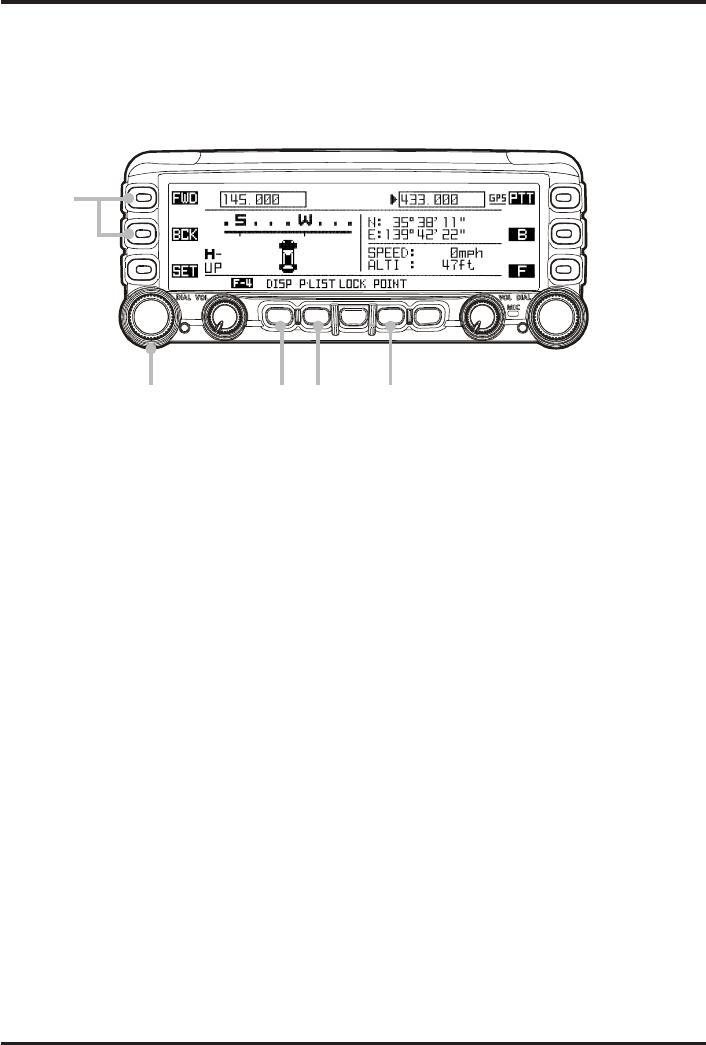
GPS OPERATION (REQUIRE OPTIONAL GPS ANTENNA UNIT)
When install the optional FGPS-1 or FGPS-2 GPS Antenna Unit, the FTM-350R al-
lows the display of your position (Longitude/Latitude).
Before beginning the GPS operation, enables the “GPS” page via Set Mode item “C01
DISPLAY SELECT” in the “DISPLAY” group. See page 33.
1Press the [FWD] or [BCK] key repeatedly, until the “GPS” Page appears.
Your current position (Longitude/Latitude) appears at the upper right of the display,
and your current altitude and vehicle speed appears at the lower right of the display.
Additionally, your course direction (compass) displays in the left half of the display.
2Press the [DISP] key to change the compass. Available selections are “Compass Rose
(North Up)”, “Compass Rose (Heading Up)”, and “Compass Tape”.
3Press the [POINT] key to store the current position and date into the “Point” memory,
if desired. Available “Point” memories are four groups, and there is four Channel for
each group.
4Press the [PyLIST] key to open the “Point” memory list. Rotate the left side [DIAL]
knob to scroll the list and press the [BCK] key to close the list. You may delete the
desired point from the “Point” memory list by pressing the [DEL] key, if desired.
To return to the “Radio” page, press the [FWD] or [BCK] key repeatedly, until the “Radio”
Page appears.
You may change the unit of the altitude and vehicle speed via Set Mode item “G10 UNIT
SELECT” in the “SYSTEM” group (see page 37), and also change the time format via Set
Mode item “I02 DATE&TIME FORMAT” in the “TIMER/CLOCK” group (see page
39).
: The FGPS-2 GPS Antenna Unit requires CT-133 GPS Antenna Cable and CT-136
GPS Antenna Adapter.
1
3424
FCC ID: K6620335X40
IC: 511B-20335X40
FTM-350R OPERATING MANUAL 25
GPS OPERATION (REQUIRE OPTIONAL GPS ANTENNA UNIT)
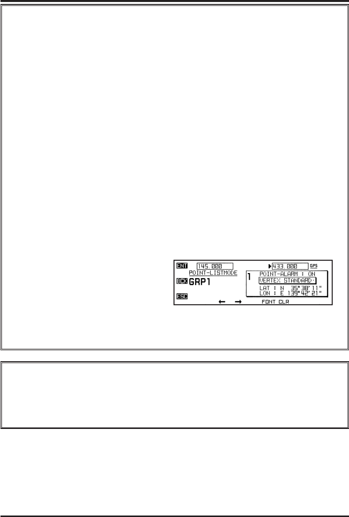
“Point” memory
The FTM-350R has 16 “point” memories (four channels in four group each) which
memory your positon (Longitude/Latitude) and its date.
When your vehicle nears to one of that “Point” memory, the “Nav” pop-up win-
dow will open for ten seconds even if you display any page.
You may customize the time when a window opens via Set mode item “H03 NAVI
POPUP” in the “NAVI” group. And also, you may change the “date” to your
desired name, such as the place name, by the following procedures:
1. Press the [PyLIST] key to open the “Point” memory list.
2. Rotate the left side [DIAL] knob to select the “Point” memory you wish to
change the “date”.
3. Press the left side [DIAL] knob to appear the detail data of the “Point” memory.
4. Press the left side [DIAL] knob again to enable edit of the stored data.
5. Rotate the left side [DIAL] knob to toggle the point alarm function on and off.
When this selection is set to “OFF”, the “Nav” pop-up window do not open
even if your vehicle nears to that “Point” memory.
6. Press the [] key to move the cursor to the “date” area, then press the [CLR]
key to clear previous data.
7. Enter the desired name the left side
[DIAL] knob (select character/num-
ber) and the [] / [] key (move
the cursor).
8. Press the [ENT] key to overwrite the new setting.
9. Press the [NAVI] key to return to the “GPS” page, then press the [NAVI] key
again to initiate the navigation.
Impotant Note
When the GPS Antenna Unit is first turned on, it may take several minutes to
complete a fix of your position. This is normal, as the GPS unit is downloding
“almanac” information from the GPS satellites.
FCC ID: K6620335X40
IC: 511B-20335X40

FTM-350R OPERATING MANUAL26
NAVI OPERATION (REQUIRE OPTIONAL GPS ANTENNA UNIT)
The FTM-350R enables to navigate to the position memorized in the “Point” memory
beforehand by simple operation.
Before beginning the Navigation, enables the “NAVI” page via Set Mode item “C01 DIS-
PLAY SELECT” in the “DISPLAY” group. See page 33.
1Press the [FWD] or [BCK] key repeatedly, until the “NAVI” Page appears.
2Press the [PyLIST] key to open the “Point” memory list, then rotate the left side [DIAL]
knob to select the destination where you wish to go.
3Press the [NAVI] key to return to the “NAVI” Page. The destination appears at the
upper right of the display, and distance between your current position and destination
appears at the lower right of the display. Additionally, your course direction (compass)
displays in the left half of the display.
4Press the [NAVI] key to initiate the navigation. Drive your vehicle so that the “CAR”
icon turns to a “D” symbol in the Compass display.
When your vehicle nears to the destination, emits the alarm beep and “GOAL!” notation
appears in the Compass display.
To return to the “Radio” page, press the [FWD] or [BCK] key repeatedly, until the “Radio”
Page appears.
You may customize the NAVI operation via the “NAVI” group of the Set Mode (see page
38).
42
1
FCC ID: K6620335X40
IC: 511B-20335X40

FTM-350R OPERATING MANUAL 27
NAVI OPERATION (REQUIRE OPTIONAL GPS ANTENNA UNIT)
To Navigate to the New Point
If you wish to navigate the place without your having still gone, examine the lon-
gitude/latitude of that place from the map, then overwrite that data into the one of
the “Point” memory previously stored.
1. Press the [PyLIST] key to open the “Point” memory list.
2. Rotate the left side [DIAL] knob to select the “Point” memory you wish to
overwrite.
3. Press the left side [DIAL] knob to appear the detail data of the “Point” memory.
4. Press the left side [DIAL] knob again to enable edit of the stored data.
5. Edit the stored data to new point by the left side [DIAL] knob (select character/
number) and the [] / [] key (move the cursor).
6. Press the [ENT] key to overwrite the new setting.
7. Press the [NAVI] key to return to the “NAVI” Page, then press the [NAVI] key
again to initiate the navigation.
Press the [POINT] key to store the current position and date into the “Point” memory, if
desired. Available “Point” memories are four groups, and there is four Channel for
each group.
FCC ID: K6620335X40
IC: 511B-20335X40

FTM-350R OPERATING MANUAL28
The FTM-350R has 87 items in the Set Mode, and they are grouped. It will be convenient
for you, if you initially select the group by rotating the left side [DIAL] knob, and then
rotate the left side [DIAL] knob to select the item you want after pressing the left side
[DIAL] knob. When you have finished making your adjustment, press the [ESC] key re-
peatedly, until the FTM-350R returns to normal operation.
The groups are as follows.
A: AUDIO, see page 29.
B: TX/RX, see page 31.
C: DISPLAY, see page 33.
D: MEMORY, see page 34.
E: APRS/PKT, refer to the “APRS Manual”.
F: SCAN, see page 35.
G: SYSTEM, see page 36.
H: NAVI, see page 38.
I: TIMER/CLOCK, see page 39.
J: SIGNALING, see page 40.
K: OPTION, see page 42.
M
ISCELLANEOUS
S
ETTING
(S
ET
M
ODE
O
PERATION
)
FCC ID: K6620335X40
IC: 511B-20335X40

FTM-350R OPERATING MANUAL 29
A01: AF DIFFERENTIAL
Function: Enables/Disables the AVC (Automatic Audio Volume Controller).
The AVC allows the most comfortable and/or effective reception in noisy environment.
Available Values: OFF, MIN, MID, or MAX
Default: OFF
OFF: Disables the AVC.
MIN: Activates the AVC with the low effect level.
MID: Activates the AVC with the medium effect level.
MAX: Activates the AVC with the high effect level.
A02: AF TONE CONTROL
Function: Selects the tome pitch control for the received audio.
Available Values: HIGH-2, HIGH-1, NORMAL, LOW-1, or LOW-2
Default: NORMAL
HIGH-2: The received audio is enhanced in the high-range frequency with the high
effect level.
HIGH-1: The received audio is enhanced in the high-range frequency with the low ef-
fect level.
NORMAL: The received audio does not pass through the tome pitch control.
LOW-1: The received audio is enhanced in the low-range frequency with the low effect
level.
LOW-2: The received audio is enhanced in the low-range frequency with the high ef-
fect level.
A03: SPEAKER
Function: Selects the speaker to be used:
Available Values: FRONT+REAR, FRONT, OFF, or REAR
Default: FRONT+REAR
FRONT+REAR: Output the receiving audio from FRONT (located in the front panel) and
REAR (located in the transceiver’s body) speakers.
FRONT: Output the receiving audio from FRONT speaker.
OFF: Disable the FRONT and REAR speakers.
REAR: Output the receiving audio from REAR speaker.
AUDIO GROUP
M
ISCELLANEOUS
S
ETTING
(S
ET
M
ODE
O
PERATION
)
FCC ID: K6620335X40
IC: 511B-20335X40

FTM-350R OPERATING MANUAL30
AUDIO GROUP
A04: STEREO/MONO
Function: Selects the audio output.
Available Values: MONAURAL or STEREO
Default: MONAURAL
A05: SUB BAND MUTE
Function: Selects the operation method of the MUTE function during dual receive opera-
tion.
Available Values: OFF, TX MUTE, RX MUTE, or TRX MUTE
Default: OFF
OFF: Disable the MUTE function.
TX MUTE: Disables the sub band’s receiver audio output while transmit on the main
band.
RX MUTE: Disables the sub band’s receiver audio output when receive the signal on the
main band.
TRX MUTE: Disables the sub band’s receiver audio output while transmit on the main
band, and when receive the signal on the main band.
M
ISCELLANEOUS
S
ETTING
(S
ET
M
ODE
O
PERATION
)
FCC ID: K6620335X40
IC: 511B-20335X40

FTM-350R OPERATING MANUAL 31
B01: MIC GAIN
Function: Adjust the microphone gaine level.
Available Values: MIN, LOW, NORMAL, HIGH, or MAX
Default: NORMAL
B02: PTT MODE
Function: Selects the front panel’s PTT key function.
Available Values: MOMENTARY / TOGGLE
Default: MOMENTARY
B03: RPT SHIFT DIREC
Function: Sets the repeater shift direction.
Available Values: SHIFT OFF, SHIFT–, or SHIFT+
Default: OFF
B04: RPT SHIFT FREQ
Function: Sets the magnitude of the repeater shift.
Available Values: 0.00 - 99.95 MHz (50 kHz/step)
Default: Depends on the operating band.
B05: RX EXPANSION
Function: Enables/Disables the band expansion.
Available Values: GENERAL or WIDE COVERAGE
Default: GENERAL
When this Set Mode item is set to “WIDE COVERAGE”, you will receive the 108 - 137
MHz and 480 - 999.9875 MHz bands (Cellular blocked).
B06: VOX
Function: Enables/Disables the VOX operation.
Available Values: OFF, REAR HAND-MIC, FRONT HAND-MIC, or INTERNAL MIC
Default: OFF
OFF: Disable the VOX operation.
REAR HAND-MIC: Enable the VOX operation for the microphone which is connected
to the rear panel MIC jack (located in the transceiver’s body).
FRONT HAND-MIC: Enable the VOX operation for the microphone which is connected
to the front panel MIC jack (located in the control head).
INTERNAL MIC: Enable the VOX operation for the microphone which is connected
to the front panel microphone.
TX/RX GROUP
M
ISCELLANEOUS
S
ETTING
(S
ET
M
ODE
O
PERATION
)
FCC ID: K6620335X40
IC: 511B-20335X40

FTM-350R OPERATING MANUAL32
TX/RX GROUP
B07: VOX SENSITIVITY
Function: Sets the VOX sensitivity.
Available Values: MIN, LOW, NORMAL, HIGH, or MAX
Default: NORMAL
B08: WIDE / NARROW AUTO
Function: Selects the receivng mode.
Available Values: AUTO, WIDE FM, FM, NARROW FM, or AM
Default: AUTO
B09: WX ALERT
Function:Enables/Disables the weather alert scan feature.
Available Values: ON or OFF
Default: OFF
M
ISCELLANEOUS
S
ETTING
(S
ET
M
ODE
O
PERATION
)
FCC ID: K6620335X40
IC: 511B-20335X40

FTM-350R OPERATING MANUAL 33
DISPLAY GROUP
C01: DISPLAY SELECT
Function: Enables/Disable the operating function pages recalls from the [FWD]/[BCK]
key.
Available Values: FREQUENCY: ON or OFF, TIMER/CLOCK: ON or OFF,
BARO/ALTI: ON or OFF
Default: FREQUENCY: ON, TIMER/CLOCK: ON, BARO/ALTI: OFF
C02: LCD BRIGHTNESS
Function: Sets the display’s illumination level.
Available Values: MIN, 2, 3, 4, 5, 6, 7, or MAX
Default: MAX
C03: LCD COLOR
Function: Selects the display’s backlight color.
Available Values: WHITE-BLUE, SKY-BLUE, MARINE-BLUE, GREEN,
YELLOW-GREEN, ORANGE, or UMBER
Default: WHITE-BLUE
C04: LCD CONTRAST
Function: Sets the display’s contrast level.
Available Values: MIN, 2, 3, 4, 5, 6, 7, or MAX
Default: 4
M
ISCELLANEOUS
S
ETTING
(S
ET
M
ODE
O
PERATION
)
FCC ID: K6620335X40
IC: 511B-20335X40

FTM-350R OPERATING MANUAL34
MEMORY GROUP
D01: MEMORY DISPLAY
Function: Selects the memory channel indication between the “Frequency” and the channel’s
“Alpha-numeric Tag”.
Available Values: FREQUENCY or ALPHA
Default: FREQUENCY
D02: MEMORY EDIT
Function: Accesses to the memory edit window.
D03: MEMORY SCAN TYPE
Function: Selects what action will happen on a “flagged” memory channel.
Available Values: ALL MEMORY or SELECT MEMORY
Default: ALL MEMORY
ALL MEMORY: The scanner will “skip” the flagged (SKIP) channels during scan-
ning.
SELECT MEMORY: The scanner will “only scan” the flagged (SELECT) channels dur-
ing scanning.
D04: MEMORY SKIP / SELCT
Function: Selects the “scan flag” to the current memory channel.
Available Values: OFF, SKIP, or SELECT
Default: OFF
OFF: All memory channels will be scanned
SKIP: The current memory channel is set to scan “SKIP” channel.
SELECT: The current memory channel is set to scan “SELECT” channel.
M
ISCELLANEOUS
S
ETTING
(S
ET
M
ODE
O
PERATION
)
FCC ID: K6620335X40
IC: 511B-20335X40

FTM-350R OPERATING MANUAL 35
F01: DUAL WATCH STOP
Function: Selects the Dual Watch resume mode.
Available Values: AUTO or HOLD
Default: AUTO
AUTO: The Dual Watch feature will stop when the signal is received on the priority
channel. When the signal drops, the Dual Watch will resume.
HOLD: The Dual Watch feature will stop when the signal is received on the priority
channel. It will not restart automatically.
F02: SCAN DIRECTION
Function: Select the scan start direction while initiates the scanner using the scan com-
mand by pressing the [SCAN] key.
Available Values: UP START or DOWN START
Default: UP START
F03: SCAN RESUME
Function: Selects the scan resume mode.
Available Values: BUSY, HOLD, TIME 1 sec, TIME 3 sec, or TIME 5 sec
Default: BUSY
BUSY: The scanner will holt on a signal it encounters. When the signal drops, the
scanner will resume.
HOLD: The scanner will holt on a signal it encounters. It will not restart automati-
cally.
TIME 1 sec: The scanner will holt on a signal it encounters, and scanner will resume after
one second.
TIME 3 sec: The scanner will holt on a signal it encounters, and scanner will resume after
three seconds.
TIME 5 sec: The scanner will holt on a signal it encounters, and scanner will resume after
five seconds.
F04: SCAN STOP BEEP
Function: Enables/Disables the scan stop beep.
Available Values: ON or OFF
Default: OFF
SCAN GROUP
M
ISCELLANEOUS
S
ETTING
(S
ET
M
ODE
O
PERATION
)
FCC ID: K6620335X40
IC: 511B-20335X40

FTM-350R OPERATING MANUAL36
SYSTEM GROUP
G01: APO
Function: Sets the Automatic Power-Off time.
Available Values: OFF, 0.5 hour, 1.0 hour, 1.5 hour, 2.0 hour ~ 12.0 hour (1.0 hour/step)
Default: OFF
G02: ARS
Function: Enables/Disables the Automatic Repeater Shift function.
Available Values: ON or OFF
Default: OFF
G03: AUTO STEP
Function: Selects the DIAL frequncy step.
Available Values: AUTO, 5.00 kHz, 6.25 kHz, 8.33 kHz, 9.00 kHz, 10.00 kHz, 12.50 kHz,
15.00 kHz, 20.00 kHz, 25.00 kHz, 50.00 kHz, or 100.00 kHz
Default: AUTO
G04: BEEP
Function: Adjusts the beep volume level.
Available Values: OFF, LOW, or HIGH
Default:
G05: F KEY
Function: Selects the function of the front panel’s [F] key
Available Values: V/M, MHz, AF DUAL 1 (LINE-IN), AF DUAL 2 (AM),
AF DUAL 3 (FM), PA, SQL OFF, T-CALL, or WiRES
Default: AF DUAL 3 (FM)
G06: MIC P KEY
Function: Selects the function of the microphone’s [P1]/[P2]/[P3]/[P4] programmable
keys.
Available Values: BAND SCOPE, SCAN, SQL TYPE, DCS CODE, TONE FREQ,
RPT SHIFT, REVERSE, TX POWER, SQL OFF, T-CALL, WiRES, or WX
Default: P1: , P2: , P3: , P4:
G07: OPERATION MODE
Function: Shifting of CPU clock frequency.
Available Values: A or B
Default: A
This Set Mode item is only used to move a sprious response “birdie”, shold it fall on a
desired frequncy.
M
ISCELLANEOUS
S
ETTING
(S
ET
M
ODE
O
PERATION
)
FCC ID: K6620335X40
IC: 511B-20335X40

FTM-350R OPERATING MANUAL 37
G08: RX COVERAGE
Function: Enables or disables the band limiting for the VFO frequncy selecting and memory
channel recalling.
Available Values: VFO: IN BAND or ALL, MEMORY: IN BAND or ALL
Default: VFO: IN BAND, MEMORY: ALL
VFO IN BAND: When the VFO frequency reaches the high band edge of the cur-
rent band, the VFO frequency will jamp to the low band edge of
the current band (or vice versa).
VFO ALL: When the VFO frequency reaches the high band edge of the cur-
rent band, the VFO frequency will jamp to the low band edge of
the next band (or vice versa).
MEMORY IN BAND: Recalls only the memory channel which store the same band as a
current memory channel.
MEMORY ALL: Recalls the all memory channels regardless of a band.
G09: TOT
Function: Sets the TOT time. When your transmission time reaches the selected time, the
transceiver returns to the RX mode automatically.
Available Values: OFF, 5 min, 10 min, 15min, 20 min, or 30 min
Default: OFF
G10: UNIT SELECT
Function: Selects the measurement units of the environment sensor.
Available Values: METER or YARD-POUND
Default: YARD-POUND
SYSTEM GROUP
M
ISCELLANEOUS
S
ETTING
(S
ET
M
ODE
O
PERATION
)
FCC ID: K6620335X40
IC: 511B-20335X40

FTM-350R OPERATING MANUAL38
NAVI GROUP
H01: ALARM VOLUME
Function: Select the volume level of the alarm when the FTM-350R arrived at the destina-
tion.
Available Values: OFF, LOW, or HIGH
Default: LOW
H02: DESTINATION AREA
Function: Select the threshold range of the destination.
Available Values: 0.05 mile, 0.1 mile, 0.2 mile, 0.3 mile, 0.5 mile, 1.0 mile, or 2.0 mile
Default: 0.1 mile
H03: NAVI POPUP
Function: Selects the “NAVI” Pop-up function.
Available Values: OFF, 1 sec ~ 30 sec, or CONTINUOUS
Default: 10 sec
M
ISCELLANEOUS
S
ETTING
(S
ET
M
ODE
O
PERATION
)
FCC ID: K6620335X40
IC: 511B-20335X40