Yaesu Musen 20461X50 Scanning Receiver User Manual FTDX3000 Operating Manual
Yaesu Musen Co., Ltd. Scanning Receiver FTDX3000 Operating Manual
UserManual.wiki
>
Yaesu Musen
>
20461X50 User Manual
>
Users Manual 2
Contents
1.
Users Manual 1
2.
Users Manual 2
3.
Users Manual 3
4.
Users Manual 4
5.
Users Manual 5
6.
Users Manual 6
7.
Users Manual 7
8.
Users Manual 8
9.
Users Manual 9
10.
Users Manual 10
11.
Users Manual 11
12.
Users Manual 12
13.
Users Manual 13
14.
Users Manual 14
Users Manual 2
Navigation menu
Upload a User Manual
Namespaces
Wiki Guide
HTML
PDF
Info
Views
User Manual
Discussion / Help
Navigation
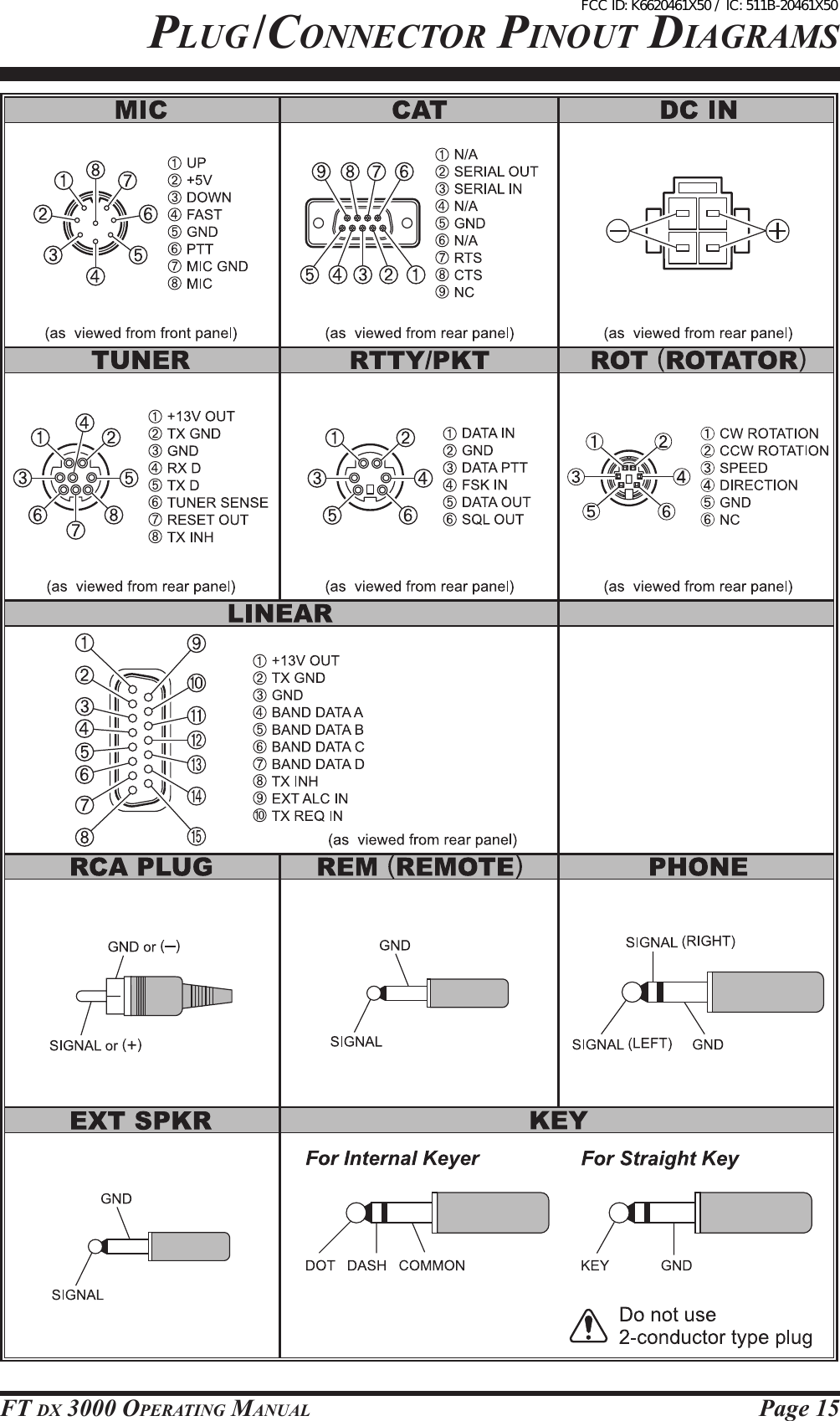
![Page 16 FT DX 3000 OperaTing Manual[POWER] Switch Pressandholdinthisswitchforonesecondtoturnthe transceiver on. Similarly, press and hold in thisswitchforonesecondtoturnthetransceiveroff.[TUNE] Switch Thisistheon/offswitch for the FTDX3000’sAuto-maticAntennaTuner. Pressingthisbuttonmomentarilyplacestheantennatuner in line between the transmitter nal amplierand the antenna jack (The “ ” icon will ap-pearinthedisplay).Receptionisnotaffected. Pressingandholdinginthisbuttonfortwoseconds,whilereceivinginanamateurband,activatesthetransmitterfor afewseconds whilethe automaticantennatunerrematchestheantennasystemimped-anceforminimumSWR.Theresultingsettingisau-tomaticallystoredinoneoftheantennatuner’s100memories,forinstantautomaticrecalllaterwhenthereceiveristunednearthesamefrequency. Pressingthisbuttonmomentarily,whiletheTunerisengaged,willtaketheAutomaticAntennatuneroutofthetransmitline.Note: WhentheAutomaticAntennaTuneristuningitself,a signal is being transmitted.Therefore, be certainthat an antenna or dummy load is connected to theselectedantennajackbeforepressingandholdinginthe[TUNE]buttontostartantennatuning.KEY Jack This1/4-inch,3-contactjack acceptsaCWkeyorkeyerpaddles(forthebuilt-inelectronickeyer),oroutputfromanexternalelectronickeyer.Pinoutisshownon page 15. Key up voltage is+3.3 V DC,andkeydown currentis 0.3mA.Thisjackmaybe congured for keyer, “Bug”, “straight key”, orcomputerkeyinginterfaceoperationviaMenuitem“018 KEYER F KEYER TYPE”(seepage???).Thereisanotherjackwiththesamenameontherearpanel,anditmaybeconguredindependentlyforInternalKeyerorpseudo-straight-keyoperation.Note: Youcannotusea2-contactpluginthisjack(todosoproducesaconstant“keydown”condition).FrOnT panel COnTrOls & swiTChesFCC ID: K6620461X50 / IC: 511B-20461X50](https://usermanual.wiki/Yaesu-Musen/20461X50.Users-Manual-2/User-Guide-1770287-Page-3.png)
![Page 17FT DX 3000 OperaTing ManualFrOnT panel COnTrOls & swiTChesPHONES Jack A1/4-inch,3-contactjackacceptseithermonauralorstereoheadphoneswith2-or3-contactplugs.Whenaplugisinserted,theloudspeakerisdisabled.Note: Whenwearingheadphones,werecommendthatyouturntheAFGainlevelsdowntotheirlowestsettingsbeforeturningpoweron,tominimizetheimpactonyourhearingcausedbyaudio“pops”duringswitch-on. Microphone Connector This8-pinjackacceptsinputfromamicrophoneuti-lizingatraditionalYAESUHFtransceiverpinout.[ANT] Switch Pressing this switch selects the ANT 1, ANT 2 ortheANT 3connectoron the rear panel, and allowsconvenientantennaswitchingatthepressofbutton.Theselectedantennajack is indicatedontheBlockDiagramDisplayshownintheTransceiverDisplay.[IPO] (INtercept poINt optImIzatIoN) Switch This button may be used to set the optimum frontendcharacteristics of the receiver circuit for averystrong signal environment.Available selections areAMP 1 (low distortion amplifier),AMP 2 (2-stagelow-distortion RF amplifier), or IPO (bypasses thefrontendRFamplier),andtheselectedreceiverRFamplifierappearsintheIPO columnoftheBlockDiagramDisplayonthedisplay.[ATT] Switch Thisbuttonselectsthedegreeofattenuation,ifany,tobeappliedtothereceiverinput. Availableselectionsare–6dB,–12dB,–18dB,orOFF. The attenuation level appears in theATT col-umnoftheBlockDiagramDisplayonthedisplay.advIce: TheAttenuatormaybeusedinconjunctionwiththe[IPO]buttontoprovide twostagesofsignalreduc-tionwhenanextremely strongsignalisbeingre-ceived.[R.FLT] (roofINg fIlter) Switch ThisbuttonselectsthebandwidthofthereceiverrstIF Roong Filter.Available selections are 3 kHz, 6kHz, 15 kHz, orAuto. The selected bandwidthap-pears in the R.FLT column of the Block DiagramDisplayonthedisplay.advIce: Because the roong lter is in the rst IF, the pro-tection it provides against interferenceis quite sig-nificant.Whenset toAUTO, SSBbandwidthis 6kHz,CWis3kHz,FMandRTTYare15kHz.OnacrowdedSSBband,however,youmaywishtoselectthe3kHzlter,forthemaximumpossibleinterfer-encerejection.[NB] Switch ThisbuttonturnstheIFNoiseBlankeronandoff. Pressthis button momentarily toreduce short-dura-tionpulsenoise. AvailableselectionsareON,OFF,orNBWON.Theattenuation level appears in theATT column of theBlockDiagramDisplayonthedisplay.[AGC] Switch ThisbuttonselectstheAGCcharacteristicsforthereceiver.AvailableselectionsareFAST,MID,SLOW,orAUTO.The“AGC”iconwillchangeac-cordingtotheAGCcharacteristicsselected. Pressthe[AGC]button repeatedlytoselectthede-siredreceiver-recoverytimeconstant.Pressandholdin the [AGC] button for one second to disable theAGC(fortestingorweak-signalreception).advIce: TheAttenuatormaybeusedinconjunctionwiththe[IPO]buttontoprovidetwostagesofsignalreductionwhenanextremelystrongsignalisbe-ingreceived. IftheAGCreceiver-recoverytimeissetto“Off”bypressingandholdinginthe[AGC]button,theS-meterwillnolongerdeect.Additionally,youwill likely encounter distortion on stronger sig-nals,astheIFampliersandthefollowingstagesareprobablybeingoverloaded.[MOX] Switch PressingthisbuttonengagesthePTT(PushtoTalk)circuit,toactivate thetransmitter(theLEDinsidethisbuttonwillglowred).Itmustbeturnedoff(theredLEDwillbeoff)forreception.Thisbuttonrepli-catestheactionofthePushtoTalk(PTT)switchonthemicrophone.Whenengagingthe[MOX]button,orotherwisecausinga transmissionto bestarted,becertainyou haveeither anantenna or50-OhmdummyloadconnectedtotheselectedAntennajack.FCC ID: K6620461X50 / IC: 511B-20461X50](https://usermanual.wiki/Yaesu-Musen/20461X50.Users-Manual-2/User-Guide-1770287-Page-4.png)
![Page 18 FT DX 3000 OperaTing Manual[MIC/SPEED] Knob MIC Thisknob adjuststhemicrophoneinputlevelfor(non-processed)SSBandAMtransmission. Thedisplaywillshowthe relative microphonegainlevelfor3secondswheneverthisknobisturned.advIce: Adjust the [MIC GAIN] knob while speaking in asomewhatlouderthannormalvoicelevel,watchtheALClevelandadjustthe[MICGAIN]knobsothattheALClevelindicationjustreachestherightedgeof theALC scale. Then, when you speak in yournormalvoicelevel,youwillnotbeover-drivingthemicrophoneamplierstages. SPEED This knob adjusts the keying speed of the internalCWkeyer(4 ~60WPM).Clockwiserotationin-creasesthesendingspeed. The display will show the keying speed for 3 sec-ondswheneverthisknobisturned.[PROC/CAR] Knob PRO This knob adjusts the compression (input) levelof the transmitter RF speech processor in the SSBmode. CAR This knob adjusts the RF Power output control forthetransceiver.advIce: TheRFPoweroutputwillshowfor3secondsintherightoftheTFTDisplaywhenevertheouter[RFPWR]knobisturned. [NOTCH] Switch Pressing this button allows you to adjust the centerfrequencyoftheIFNotchlterusingthe[NOTCH]knob.Whileactivated,theLEDinsidethisbuttonglows orange. Press the [NOTCH] knob briefly totoggletheIFNotchlteron/off.FrOnT panel COnTrOls & swiTChesFCC ID: K6620461X50 / IC: 511B-20461X50](https://usermanual.wiki/Yaesu-Musen/20461X50.Users-Manual-2/User-Guide-1770287-Page-5.png)
![Page 19FT DX 3000 OperaTing ManualFrOnT panel COnTrOls & swiTChes[NOTCH] KnobPress the [NOTCH] switch to turn the IF NOTCHfilter on and off. Rotate the inner [NOTCH] knobtoadjustthecenterfrequencyoftheIFNOTCHlter.The null position of the IF NOTCH lter canbeobservedonthedisplay.Furthermore,thedisplaywillshow thecenterfrequency oftheIF NOTCHlterfor3secondswheneverthe[NOTCH]knobisturned.[CONT/APF] Knob CONT IntheSSB,AM,andFMmodes,pressthe[CONT/APF] switch to turn the inner [CONT/APF] knobselects the desired CONTOUR lter response. TheCONTOUR lter is engaged via the [CONT/APF]switch. APF IntheCWmode,pressthe[CONT/APF]switchtoturntheinner[CONT/APF]knobselectsthedesiredAPF (Audio Peak Filter) response. TheAPF is en-gagedviathe[CONT/APF]switch.[CONT/APF] Switch Pressing this button allows you to select the DSPContourfilterresponseusingthe[CONT/APF]knob.Whileactivated,theLED insidethisbuttonglows orange. Press the [CONT/APF]knob brieytotoggletheIFContourlteron/off. Furthermore, intheCWmode,pressing thisbut-ton to activate theAPF (Audio Peak Filter) whichprovides a very narrow audio bandwidth.TheAPFcircuitisanautomaticcircuit,andthereisnoadjust-mentknobfortheAPF.[SHIFTKnob] (except oN fm mode) Rotate the inner [SHIFT] to move the passband ofthe IF DSP filter by 20 Hz steps.The total adjust-mentrangeis±1kHz.Thepositionofthepassbandcanbe observedonthedisplay.Furthermore,thedisplaywillshowtheshiftvalueoftheIFSHIFTfor3secondswheneverthe[SHIFT]knobisturned.[WIDTHKnob] (except oN fm mode) Rotatetheouter[WIDTH]knobtosettheoverallbandwidth of the IF DSP filter. Counter-clockwiserotationreduces thebandwidth,whileclockwiserotationincreasesthe bandwidth.Thecurrent band-widthcanbe observed on the display. Furthermore,thefrequencydisplaywillshowthebandwidthoftheIF passband for 3 seconds whenever the [WIDTH]knobisturned.[BK-IN] Switch ThisbuttonturnstheCWbreak-incapabilityonandoff.WhileCWbreak-inisactivated,theLEDinsidethisbuttonglowsorange.[AF] KnobAFKnob Theinner[AFGAIN]knobsetsthereceiver’saudiovolume level.Typically, you will operate with thiscontrolsetbetweenthe9o’clockand10o’clockpo-sitions.[RF/SQL] Knob RF Theouter[RF/SQL]knobisthereceiver’sRFgaincontrol,whichadjuststhegainofthereceiver’sRFandIFamplierstages.Thiscontrolisnormallyleftinthefullyclockwiseposition.SQLThisknobsetsthesignallevelthreshold,belowwhich the receiver audio is muted, in all modes. Itis very useful during local rag-chews, to eliminatenoisebetweenincomingtransmissions.This controlis normally kept fully counter-clockwise (off), ex-ceptwhenscanningandduringFMoperation.[MONI] (Monitor) Switch Thisbuttonenablesthetransmitmonitorinallmodes. While activated, the LED inside this buttonglowsorange.advIce: When usingheadphones,theMonitor functionisvery helpful while adjusting the Parametric Equal-izer or other voice quality adjustments. The voiceheard in the headphones represents the transmittedaudioqualities.FCC ID: K6620461X50 / IC: 511B-20461X50](https://usermanual.wiki/Yaesu-Musen/20461X50.Users-Manual-2/User-Guide-1770287-Page-6.png)
![Page 20 FT DX 3000 OperaTing Manual[SCOPE] Switch T.B.D.[AUTO] Switch T.B.D.[MENU] Switch ThisbuttonisusedtoaccesstheMenusystem.Thevarioustransceiver characteristicsmaybe config-ured. Menu operation is described in detail, inthismanual.ImportaNt Note: Pressandholdinthe[MENU]switch,activatestheMenu. The Menu items will appear on the display;once you have changed the parameters, you mustpressandholdinthe[MENU]buttonforonesecondtosaveanycongurationchanges.[SELECT] Switch ThisbuttonisusedtoselecttheMenusystem.[] Switch ThesebuttonsselectthesettingoftheMenuitem.FrOnT panel COnTrOls & swiTChesFCC ID: K6620461X50 / IC: 511B-20461X50](https://usermanual.wiki/Yaesu-Musen/20461X50.Users-Manual-2/User-Guide-1770287-Page-7.png)
![Page 21FT DX 3000 OperaTing ManualFrOnT panel COnTrOls & swiTChes[(VFO-A)RX] Indicator/SwitchPressthisbuttontoactivatereceiveontheVFO-Afrequency.TheLEDinsidethebuttonwillglowgreenwhenthetransceiverreceivestheVFO-Afrequency. WhenthetransceiverreceivestheVFO-Afrequency,pressing this button momentarily will mute the re-ceiver,andtheindicatorwillblink.Pressingthebut-tononcemorewillrestore receiveroperation,andtheindicatorwillglowgreensteadily.[(VFO-A)TX] Indicator/Switch When this button is pushed, the LED inside thebutton will glow red; and, when the PTT switch ispressed,thetransceiverwilltransmitontheVFO-Afrequency(subjecttoanyClarieroffset,ofcourse).advIce: Ifthisindicatorisnotilluminated,itmeansthe[(VFO-B)TX]Indicator/Switch hasbeen selected(it will be glowing red). In this case, transmissionwillbeonthefrequencyandmodeprogrammedforVFO-B.[STO] (Store) Button Pressing the [STO] button copies the contents (fre-quency,mode,bandwidth,andalsoFMrepeaterfrequency shift/direction and CTCSS functions) ofVFO-A,intoconsecutiveQMBMemories.[RCL] (Recall) Button Pressingthe[RCL] button,recallsoneofuptoveQuickMemoryBankmemoriesforoperation.[NAR] (Narrow) SwitchIn the SSB/CW/RTTY/PSK modes, this button isusedto settheDSP(digital)IFfilterstoNarrowbandwidth.advIce: You may adjust the bandwidth using the [WIDTH]knob.In the AM mode, this button is used to toggle thereceiver’sbandwidthbetweenwide(9kHz)andnar-row(6kHz).In the FM modeonthe28MHzand50MHzbands,thisbuttonisusedtotoggletheFMdeviation/band-widthbetweenwide(±5.0 kHzDev./25.0kHzBW)andnarrow(±2.5kHzDev./12.5kHzBW).[SPLIT] Switch PressthisbuttontooperatesplitfrequencybetweenVFO-A (usedforreception)andVFO-B(usedfortransmission).Ifyoupressandholdinthe[SPLIT]buttonforonesecond,the“QuickSplit”featurewillbe engaged. VFO-B will automatically be set to afrequency5kHzhigherthantheVFO-A frequency,withthesameoperatingmode.ThetransceiverwillbeplacedintheSplitmode.[TXW] (TX Watch) Switch Pressingthis buttonletsyoumonitorthe transmitfrequencywhensplitfrequencyoperationisen-gaged. Release the button to return to normal splitfrequencyoperation.FCC ID: K6620461X50 / IC: 511B-20461X50](https://usermanual.wiki/Yaesu-Musen/20461X50.Users-Manual-2/User-Guide-1770287-Page-8.png)
![Page 22 FT DX 3000 OperaTing Manual[(VFO-B)RX] Indicator/SwitchThisbuttonswitchesthereceivingfrequencytoVFO-B,the greenLED imbeddedwithinthe but-tonwill light up.When the transceiver receives theVFO-Bfrequency,pressingthisbuttonmomentarilywill mute the receiver, and the indicator will blink.Pressing the button once more will restore receiveroperation,andtheindicatorwillglowgreensteadily.[(VFO-B)TX] Indicator/Switch Thisbuttontransferscontrolofthetransmitfrequen-cy/mode to VFO-B, and the red LED in the buttonwilllightup.Pressingthisbuttonagainwilltransferfrequency/modecontrolbacktotheVFO-Aside,andthe red LED imbedded within this button will turnoff.[C.S] Switch Pressthisbuttonmomentarilytodirectlyrecallafa-voriteMenuSelection. To program a Menu selection to the [C.S] button:pressthe[MENU]buttontoenterthe Menu. SelecttheMenuitemyouwanttosetastheshortcut.Thenpress and hold in the [C.S] button for one second;thiswilllockintheselectedMenuitemastheshortcut.MainTuningDialKnob This large knob adjusts the operating frequency oftheVFO-A.Clockwiserotationofthisknobincreas-es the frequency. Default tuning increments are 10Hz(100HzinFMmode);whenthe[FAST]buttonis pressed, the tuning steps increase.The availablestepsare:advIce:ThetuningstepsfortheMainTuningDialknobareset,at the factory, to 10 Hz perstep.Via Menuitem“150 TUNING DIAL STEP”,however,youmaychangethissettingfrom10Hzto1or5Hzinstead.[FAST] Switch Pressing this button will change the tuning rate oftheMainTuningDialknob(VFO-A)to100Hz/step. Whenthisfunctionisactivated,the“FAST”appearsinthefrequencydisplay.FrOnT panel COnTrOls & swiTChesOperating MOdeLSB/USB/CW/RTTY/PKT(LSB)AM/FM/PKT(FM)Numbers in parentheses indicate steps when the [FAST] button is On.1 Step10 Hz (100 Hz)100 Hz (1 kHz)1 dial rOtatiOn10 kHz (100 kHz)100 kHz (1 MHz)FCC ID: K6620461X50 / IC: 511B-20461X50](https://usermanual.wiki/Yaesu-Musen/20461X50.Users-Manual-2/User-Guide-1770287-Page-9.png)
![Page 23FT DX 3000 OperaTing ManualFrOnT panel COnTrOls & swiTChes[AB] Switch Pressthisbuttonmomentarilytotransfer thefre-quency or memory channel data, from VFO-A toVFO-B,overwritinganypreviouscontentsinVFO-B.UsethiskeytosetbothVFO-AandVFO-Btothesamefrequencyandmode.[AB] Switch Pressing this button momentarily, exchanges thefrequency or memory channel data, of VFO-A andVFO-B.[V/M] Switch ThisbuttontogglesfrequencycontrolbetweenVFO-Aandthememorysystem.Inmemorymode,either“MCH” (Memory Channel) or “M-TUNE” will beshowntheDisplaytoindicatethecurrentselection.IfyouhavetunedthefrequencyofftheMemorychan-nel, “M-TUNE” will be displayed. Pressing the [V/M]buttonreturnsthedisplaytotheoriginalmemoryfrequency, and the “MCH”willagain be displayed.PressingitoncemorereturnsfrequencyoperationtotheVFO-A,andtheiconwillnolongerbedisplayed.[MA] Switch Pressingthis buttonmomentarily,will displaythecontents of the currently-selected memory channelfor10seconds. Holding[MA]buttoninforonesecondcopiesthedatafrom the selected memory toVFO-A,andtwobeepssound.PreviousdatainVFO-A will be over-written.[AM] Switch Pressing this button momentarily, displays the con-tents of the currently-selected memory channel for10seconds. Pressingandholdinginthiskeyforonesecond(untilthe double beep) copies the current operating dataintothecurrentlyselectedmemory channel,over-writinganypreviousdatastoredthere.[LOCK] Switch Thisbuttontoggleslockingon/offfortheMainTun-ingDialknob(VFO-A).With “Lock” on, the MainTuningDial knobcan stillbe turned,but thefre-quencywillnotchange,andthe“LOCK”appearsinthefrequencydisplay.[BAND] Keys Thesekeysallowone-touchselectionofthedesiredAmateurband(1.8~50MHz). Thekeysmayalsobeusedfordirectentryofade-siredoperatingfrequencyduringVFOoperation.FCC ID: K6620461X50 / IC: 511B-20461X50](https://usermanual.wiki/Yaesu-Musen/20461X50.Users-Manual-2/User-Guide-1770287-Page-10.png)
![Page 24 FT DX 3000 OperaTing ManualFrOnT panel COnTrOls & swiTChes[RXCLAR] Switch PressingthisbuttonactivatestheRXClarier.Thiswillallow youtotemporarilyadjustthereceivingfrequency up to ±9.99 kHz with the [CLAR/VFO-B] knob. Press this button once more to return thereceivertotheoriginalfrequency;theClarieroffsetwillberemembered,incaseyouwanttouseitagain.To cancel the Clarifier offset, press the [CLEAR]button. Press the [VFO-B/CLAR] button followed by thisswitchwillchangethetuningrateoftheMainTun-ingDialknob(VFO-B)to100Hz/step. Whenthisfunctionisactivated,the“FAST”appearsinthefrequencydisplay.[MODE] Switch This button selects the operating mode. The selec-tionsavailableare: LSBàCW(USB)àRTTY(LSB)ààDATA(LSB)àAMàLSBà Repeatedpressesthisbutton,stepthroughtheavail-ableselections. Pressand hold in the this button, will toggle to thealternatemode. Forexample,In the LSB or USB modes,pressandhold in the this button toggles between “LSB” and“USB”mode.[MHz/µT] Switch PressingthisbuttonallowsyoutotunetheVFOfre-quencydownorupin1MHzincrements,usingthe[CLAR/VFO-B]knob.[CLAR/VFO-B] Knob ThisknobusuallytunestheClarieroffsetfrequencyup to ±9.999 kHz.Additionally, it is used to adjustthefunctionsselectedwithfivebuttonslocatedaroundtheknob.effect Rotate the [CLAR/VFO-B] knob to adjust the VFO-B frequency, in the same step as the Main Tuning Dial knob.Rotate the [CLAR/VFO-B] knob to select the memory group.Rotate the [CLAR/VFO-B] knob to tune the VFO frequency in 1 MHz step.Rotate the [CLAR/VFO-B] knob to select the memory channel.fuNctIoN SwItch [(VFO-B)RX] [GRP] [MHz][MCH] FCC ID: K6620461X50 / IC: 511B-20461X50](https://usermanual.wiki/Yaesu-Musen/20461X50.Users-Manual-2/User-Guide-1770287-Page-11.png)
![Page 25FT DX 3000 OperaTing ManualFrOnT panel COnTrOls & swiTChes[TXCLAR] SwitchPressingthisbuttonactivatestheTXClarier,toal-low offsetting the transmit frequency temporarily.Press this button once more to return the transmit-tertotheoriginalfrequency;theClarifieroffsetwill be remembered, though, in case you want touseitagain.TocanceltheClarieroffset,pressthe[CLEAR]button. Press the [VFO-B/CLAR] button followed by thisswitchtoggleslockingon/offfortheCLAR/VFO-Bknob(VFO-B).With“Lock”on,theCLAR/VFO-Bknob can still be turned, but the frequency will notchange,andthe“LOCK”appearsinthedisplay.[CLEAR] Switch Pressing this button clears out any frequency offsetyouhaveprogrammedintotheClarifierregister(therebysettingtheoffsetto“Zero”).[VFO-B/CLAR] Switch Pressing this button clears out any frequency offsetyouhaveprogrammedintotheClarifierregister(therebysettingtheoffsetto“Zero”).[MCH/GRP] SwitchMCH Pressingthisbuttonallowsyoutoselectthememorychannelusingthe[CLAR/VFO-B]knob.GRP Pressingthisbuttonallowsyoutoselectthememorygroupbyturningthe[CLAR/VFO-B]knob.FCC ID: K6620461X50 / IC: 511B-20461X50](https://usermanual.wiki/Yaesu-Musen/20461X50.Users-Manual-2/User-Guide-1770287-Page-12.png)
![Page 26 FT DX 3000 OperaTing ManualS/PO Onreceive,thisindicatesthereceivedsignalstrength,fromS-0toS-9+60dBonreceiving. Ontransmit,itindicatestheRFPowerOutput,from0to150Wattsontransmit.advIce: TheSandPOmetertypescanbechangetheANA-LOGorBAR typeviathe Menuitems“012 DIS-PLAY METER TYPE SELECT”. TheS andPOmeters canbeset tothePeak-holdfunction(BARtypeonly)viatheMenuitems“013 DISPLAY BAR MTR PEAK HOLD”.BlockDiagramDisplay ANT(1,2,3): Indicatestheantennaselectedbythefrontpanel[ANT]button. IPO(AMP1,AMP2,IPO): IndicateswhichfrontendRFamplierisselectedbythefrontpanel[IPO]button. ATT(OFF,–6dB,–12dB,–18dB): Indicatestheattenuationlevel,selectedbythefrontpanel[ATT]button. R.FLT(3kHz,6kHz,15kHz): IndicatesthereceiverIFRoongFilter,whichisse-lectedbythefrontpanel[R.FLT]button. NB(OFF,ON,ON(NBW)): Indicatesthereceiver’s“short-duration”NoiseBlanker, which is selected by the front panel [NB]button. AGC(SLOW,FAST,MID): IndicatestheAGCdecaytime setting,selectedbythefrontpanel[AGC]switch.Display inDiCaTiOns (leFT siDe)CongurationIndicatorsTUNER This indicator appears when the internalAutomaticAntennaTunerisactivated.VOX Thisindicatorappears whentheautomaticvoice-actuatedtransmitterswitchingtheSSB,AM,andFMmodes.KEYER This indicator appears whenever the internal CWkeyerisactivated.PROC Thisindicatorappears wheneverthe DSPSpeechProcessorisactivated.MICEQ This indicatorappearswhenever theThree-BandParametricMicrophoneEqualizerisactivatedviatheMenu.DNR This indicator appears whenever the DigitalNoiseReductionfeatureisactivated.DNF This indicator appears whenever the Digital NotchFilterisactivated.[VOX] Indicator Thisindicatorenablesautomaticvoice-actuatedtransmitter switching in the SSB,AM, and FMmodes. While activated, the LED inside this buttonglowsred.ThecontrolsaffectingVOXoperationarethe Menu items “114 TGEN V GAIN”, “115 TGEN VOX DLY”,and“116 TGEN ANTI VOX”. Byproperadjustmentof these controls, hands-freevoice-actu-atedoperationispossible.FCC ID: K6620461X50 / IC: 511B-20461X50](https://usermanual.wiki/Yaesu-Musen/20461X50.Users-Manual-2/User-Guide-1770287-Page-13.png)
![Page 27FT DX 3000 OperaTing ManualDisplay inDiCaTiOns (CenTer)[METER] Indicator This indicator determines the function of the meterduringtransmission. Pressthisbuttontochangethemeterfunctioninthetransmitmodeasfollows:PO ALC SWR COMP ID VDD PO……PO: Indicates the RF Power Output, from 0 to150Wattsontransmit.ALC: IndicatestherelativeALCvoltage.SWR: IndicatestheStandingWaveRatio(Forward/Reected).COMP: Indicatesthespeechcompressorlevel(SSB/AMmodesonly).ID: Indicatesthenalamplierdraincurrent.VDD: Indicatesthenalamplierdrainvoltage.Indicates the RF Power Output, from 0 to 150 Watts on transmit.Indicates the relative ALC voltage.Indicates the Standing Wave Ratio (Forward: Reected), from 1.0 to 3.0.Indicates the speech compressor level, from 0 to 30 dB.Indicates the nal amplier drain current, 0 to 30 ampere.Indicates the nal amplier drain voltage (nominal value: 13.8 V).POALCSWRCOMPIDVDD [PROC] (Processor) Indicator Thisindicator enablesthe ParametricMicrophoneEqualizer and Speech Processorfor SSBtransmis-sion.WhentheParametric MicrophoneEqualizerisactivated.Adjustmentofthe Processorlevelisaccomplished via the Menu item “109 TGEN PRO-CLVL”.advIce: The Speech Processor is a tool for increasingthe averagepoweroutputthrougha compres-sion technique. However, if the Processor levelisadvancedtoofar, the increase in compressionbecomescounter-productive,asintelligibilitywillsuffer.Werecommendthatyou monitorthesoundofyoursignalusing theMonitor(withheadphones).[DNR] Indicator This indicator turns the Main band (VFO-A) re-ceiver’sDigitalNoiseReductioncircuitonandoff.Adjustment of the Noise Reduction level is ac-complishedviatheMenuitem“111 RX DSP DNR LEVEL”.[MICEQ] switch Thisindicator[DNF] Indicator ThisindicatorturnstheMainband(VFO-A)receiv-er’sDigitalNotchFilteronandoff.Thisisanauto-maticcircuit,andthereisnoadjustmentknobfortheDNF.[KEYER] Indicator ThisindicatortogglestheinternalCWkeyeronandoff.TheKeyersendingspeedisadjustedviathefrontpanel’s[SPEED]knobandtheCWHangTimeisadjustedviatheMenuitem“044 A1A DELAY”.[ZIN/SPOT] Indicator This indicatorenablesthetheCWreceiverspot-tingtone;bymatchingtheSPOTtonetothatoftheincomingCWsignal(preciselythesamepitch),youwill be “zero beating” your transmitted signal withthefrequencyoftheotherstation.Sub(VFO-B)FrequencyDisplay ThisistheSubband(VFO-B)frequencydisplay.advIce: Whenturningthe[CLAR],[PITCH],[SPEED],[CONTOUR], [NOTCH], [DNR], [DELAY],[CARRIER], [MIC], [PROC], [SHIFT], or[WIDTH]knob,eachfrequencyorvaluewillap-pearinthisareafor3seconds.If the knob is turned too slowly, the frequency display may not show the value. This is to pre-vent undesired display of the functions caused by noise or slight vibration of the controls; however, the actual value will be changed even if not displayed. You can observe the ne adjustment for a few seconds while the display is active. While adjusting functions, the display may oc-casionally skip one of the numbers in the se-quence; this is due to “rounding” of the encoder steps in the ADC converter. Set the values to your preference, they are unique to your radio and may not directly correspond to other units.DSPDisplay T.B.D.FCC ID: K6620461X50 / IC: 511B-20461X50](https://usermanual.wiki/Yaesu-Musen/20461X50.Users-Manual-2/User-Guide-1770287-Page-14.png)
![Page 28 FT DX 3000 OperaTing ManualDisplay inDiCaTiOns (righT siDe) [FAST] Indicator This indicator appears when the MainTuning Dialknob’s,tuningrateissetto“fast”. [LOCK] Indicator This indicator appears when the MainTuning Dialknobislocked.FrequencyDisplay Thisisthefrequencydisplay.LSB,USB,CW,AM,FM,RTTY,DATA Displaysthecurrentoperatingmode.SwItch[SSB][CW][AM/FM][RTTY/PKT] varIable mode SelectIoNSLSB USBCW(LSB) CW(USB)AM FMMomentarily: RTTY(LSB) PKT(LSB)Press & Hold: RTTY(LSB) RTTY(USB) or DATA(LSB) DATA(USB) PKT(FM) PKT(LSB) ....FCC ID: K6620461X50 / IC: 511B-20461X50](https://usermanual.wiki/Yaesu-Musen/20461X50.Users-Manual-2/User-Guide-1770287-Page-15.png)