Yaesu Musen 20461X50 Scanning Receiver User Manual FTDX3000 Operating Manual
Yaesu Musen Co., Ltd. Scanning Receiver FTDX3000 Operating Manual
Contents
Users Manual 2
Page 14 FT DX 30
00 OperaTing Manual
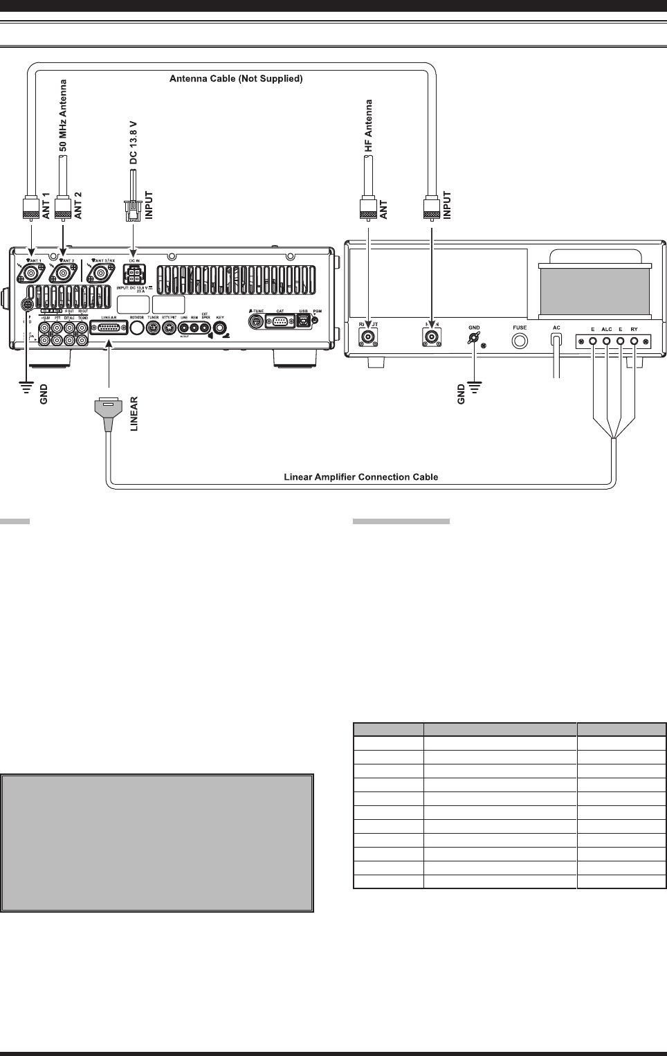
insTallaTiOn anD inTercOnnecTiOns
interFAcing to other lineAr AMpliFierS
note
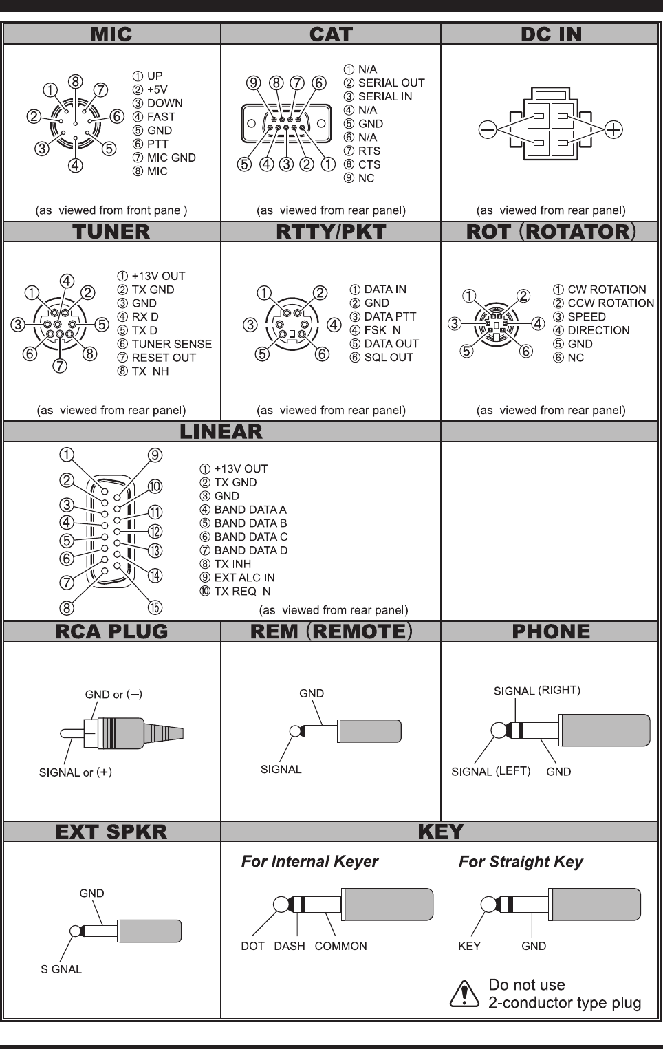
The TX GND OUT pin (pin 2) of the LINEAR jack
is a transistor “open collector” circuit. It is capable of
handling positive relay coil voltages up to +60VDC
at 200 mA or +30 VDC at 1 A. If you plan to use
multiple linear amplifiers for different bands, you
must provide external band switching of the “Linear
Tx” relay control line from the “TX GND OUT” line
at the LINEAR jack.
The specied range for ALC voltage to be used with
the FT DX 3000 is 0 to -4 Volts DC.
Amplier systems utilizing different ALC voltages
will not work correctly with the FT DX 3000, and
their ALC lines must not be connected if this is the
case.
iMportAnt note!
Do not exceed the maximum voltage or current rat-
ings for the “TX GND OUT” pin (pin 2) of the LIN-
EAR jack. This line is not compatible with negative
DC voltages, or AC voltages of any magnitude.
Most amplifier control relay systems require only
low DC voltage/current switching capability (typi-
cally, +12V DC at 25 ~ 75 mA), and the switching
transistor in the FTDX3000 will easily accommodate
such ampliers.
Wire Color
Orange
Yellow
Green
Red
White
Blue
Violet
Brown
Black
Gray
Light Blue
LINEA Jack (Pin Number)
1
2
3
4
5
6
7
8
9
10
Case
Function
+13.8 V
TX GND
GND
BAND DATA A
BAND DATA B
BAND DATA C
BAND DATA D
TX INH
EXT ALC IN
TX REQ IN
Shield
Linear Amplier Connection Cable (T9207451)
Color Code Information
Note
When the FC-40 is connected to the FTDX3000,
TX GND (pin 2) of the TUNER jack and the
LINEAR jack (pin 2) are common circuits.
Therefore, the maximum voltage at TX GND (pin
2) of the LINEAR jack must not exceed +5V.
FCC ID: K6620461X50 / IC: 511B-20461X50
Page 15FT DX 30
00 OperaTing Manual
plug /cOnnecTOr pinOuT DiagraMs
FCC ID: K6620461X50 / IC: 511B-20461X50
Page 16 FT DX 30
00 OperaTing Manual
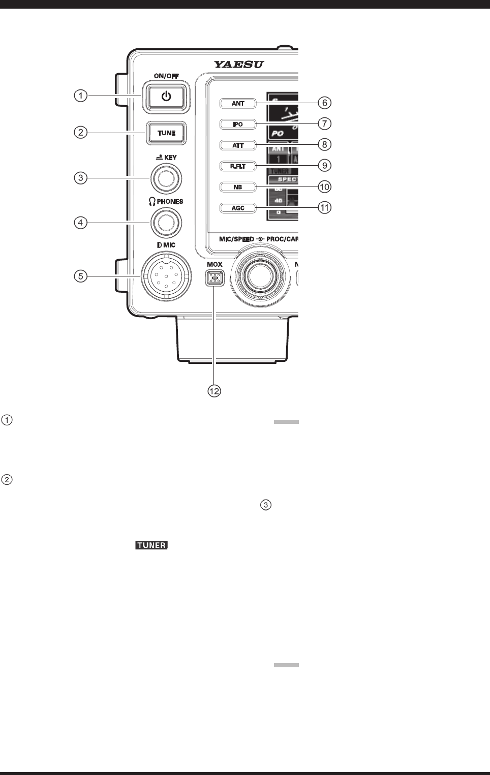
[POWER] Switch
Pressandholdinthisswitchforonesecondtoturn
the transceiver on. Similarly, press and hold in this
switchforonesecondtoturnthetransceiveroff.
[TUNE] Switch
Thisistheon/offswitch for the FTDX3000’sAuto-
maticAntennaTuner.
Pressingthisbuttonmomentarilyplacestheantenna
tuner in line between the transmitter nal amplier
and the antenna jack (The “ ” icon will ap-
pearinthedisplay).Receptionisnotaffected.
Pressingandholdinginthisbuttonfortwoseconds,
whilereceivinginanamateurband,activatesthe
transmitterfor afewseconds whilethe automatic
antennatunerrematchestheantennasystemimped-
anceforminimumSWR.Theresultingsettingisau-
tomaticallystoredinoneoftheantennatuner’s100
memories,forinstantautomaticrecalllaterwhenthe
receiveristunednearthesamefrequency.
Pressingthisbuttonmomentarily,whiletheTuneris
engaged,willtaketheAutomaticAntennatunerout
ofthetransmitline.
Note:
WhentheAutomaticAntennaTuneristuningitself,
a signal is being transmitted.Therefore, be certain
that an antenna or dummy load is connected to the
selectedantennajackbeforepressingandholdingin
the[TUNE]buttontostartantennatuning.
KEY Jack
This1/4-inch,3-contactjack acceptsaCWkeyor
keyerpaddles(forthebuilt-inelectronickeyer),or
outputfromanexternalelectronickeyer.Pinoutis
shownon page 15. Key up voltage is+3.3 V DC,
andkeydown currentis 0.3mA.Thisjackmay
be congured for keyer, “Bug”, “straight key”, or
computerkeyinginterfaceoperationviaMenuitem
“018 KEYER F KEYER TYPE”(seepage???).There
isanotherjackwiththesamenameontherearpanel,
anditmaybeconguredindependentlyforInternal
Keyerorpseudo-straight-keyoperation.
Note:
Youcannotusea2-contactpluginthisjack(todoso
producesaconstant“keydown”condition).
FrOnT panel COnTrOls & swiTChes
FCC ID: K6620461X50 / IC: 511B-20461X50
Page 17FT DX 30
00 OperaTing Manual
FrOnT panel COnTrOls & swiTChes
PHONES Jack
A1/4-inch,3-contactjackacceptseithermonauralor
stereoheadphoneswith2-or3-contactplugs.When
aplugisinserted,theloudspeakerisdisabled.
Note:
Whenwearingheadphones,werecommendthatyou
turntheAFGainlevelsdowntotheirlowestsettings
beforeturningpoweron,tominimizetheimpacton
yourhearingcausedbyaudio“pops”duringswitch-
on.
Microphone Connector
This8-pinjackacceptsinputfromamicrophoneuti-
lizingatraditionalYAESUHFtransceiverpinout.
[ANT] Switch
Pressing this switch selects the ANT 1, ANT 2 or
theANT 3connectoron the rear panel, and allows
convenientantennaswitchingatthepressofbutton.
Theselectedantennajack is indicatedontheBlock
DiagramDisplayshownintheTransceiverDisplay.
[IPO] (
INtercept poINt optImIzatIoN
) Switch
This button may be used to set the optimum front
endcharacteristics of the receiver circuit for avery
strong signal environment.Available selections are
AMP 1 (low distortion amplifier),AMP 2 (2-stage
low-distortion RF amplifier), or IPO (bypasses the
frontendRFamplier),andtheselectedreceiverRF
amplifierappearsintheIPO columnoftheBlock
DiagramDisplayonthedisplay.
[ATT] Switch
Thisbuttonselectsthedegreeofattenuation,ifany,
tobeappliedtothereceiverinput.
Availableselectionsare–6dB,–12dB,–18dB,or
OFF. The attenuation level appears in theATT col-
umnoftheBlockDiagramDisplayonthedisplay.
advIce:
TheAttenuatormaybeusedinconjunctionwiththe
[IPO]buttontoprovide twostagesofsignalreduc-
tionwhenanextremely strongsignalisbeingre-
ceived.
[R.FLT] (
roofINg fIlter
) Switch
Thisbuttonselectsthebandwidthofthereceiverrst
IF Roong Filter.Available selections are 3 kHz, 6
kHz, 15 kHz, orAuto. The selected bandwidthap-
pears in the R.FLT column of the Block Diagram
Displayonthedisplay.
advIce:
Because the roong lter is in the rst IF, the pro-
tection it provides against interferenceis quite sig-
nificant.Whenset toAUTO, SSBbandwidthis 6
kHz,CWis3kHz,FMandRTTYare15kHz.Ona
crowdedSSBband,however,youmaywishtoselect
the3kHzlter,forthemaximumpossibleinterfer-
encerejection.
[NB] Switch
ThisbuttonturnstheIFNoiseBlankeronandoff.
Pressthis button momentarily toreduce short-dura-
tionpulsenoise.
AvailableselectionsareON,OFF,orNBWON.The
attenuation level appears in theATT column of the
BlockDiagramDisplayonthedisplay.
[AGC] Switch
ThisbuttonselectstheAGCcharacteristicsfor
thereceiver.AvailableselectionsareFAST,MID,
SLOW,orAUTO.The“AGC”iconwillchangeac-
cordingtotheAGCcharacteristicsselected.
Pressthe[AGC]button repeatedlytoselectthede-
siredreceiver-recoverytimeconstant.Pressandhold
in the [AGC] button for one second to disable the
AGC(fortestingorweak-signalreception).
advIce:
TheAttenuatormaybeusedinconjunctionwith
the[IPO]buttontoprovidetwostagesofsignal
reductionwhenanextremelystrongsignalisbe-
ingreceived.
IftheAGCreceiver-recoverytimeissetto“Off”
bypressingandholdinginthe[AGC]button,the
S-meterwillnolongerdeect.Additionally,you
will likely encounter distortion on stronger sig-
nals,astheIFampliersandthefollowingstages
areprobablybeingoverloaded.
[MOX] Switch
PressingthisbuttonengagesthePTT(PushtoTalk)
circuit,toactivate thetransmitter(theLEDinside
thisbuttonwillglowred).Itmustbeturnedoff(the
redLEDwillbeoff)forreception.Thisbuttonrepli-
catestheactionofthePushtoTalk(PTT)switchon
themicrophone.Whenengagingthe[MOX]button,
orotherwisecausinga transmissionto bestarted,
becertainyou haveeither anantenna or50-Ohm
dummyloadconnectedtotheselectedAntennajack.
FCC ID: K6620461X50 / IC: 511B-20461X50
Page 18 FT DX 30
00 OperaTing Manual
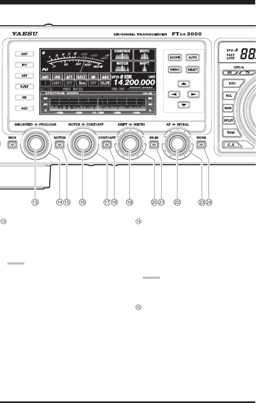
[MIC/SPEED] Knob
MIC
Thisknob adjuststhemicrophoneinputlevelfor
(non-processed)SSBandAMtransmission.
Thedisplaywillshowthe relative microphonegain
levelfor3secondswheneverthisknobisturned.
advIce:
Adjust the [MIC GAIN] knob while speaking in a
somewhatlouderthannormalvoicelevel,watchthe
ALClevelandadjustthe[MICGAIN]knobsothat
theALClevelindicationjustreachestherightedge
of theALC scale. Then, when you speak in your
normalvoicelevel,youwillnotbeover-drivingthe
microphoneamplierstages.
SPEED
This knob adjusts the keying speed of the internal
CWkeyer(4 ~60WPM).Clockwiserotationin-
creasesthesendingspeed.
The display will show the keying speed for 3 sec-
ondswheneverthisknobisturned.
[PROC/CAR] Knob
PRO
This knob adjusts the compression (input) level
of the transmitter RF speech processor in the SSB
mode.
CAR
This knob adjusts the RF Power output control for
thetransceiver.
advIce:
TheRFPoweroutputwillshowfor3secondsinthe
rightoftheTFTDisplaywhenevertheouter[RF
PWR]knobisturned.
[NOTCH] Switch
Pressing this button allows you to adjust the center
frequencyoftheIFNotchlterusingthe[NOTCH]
knob.Whileactivated,theLEDinsidethisbutton
glows orange. Press the [NOTCH] knob briefly to
toggletheIFNotchlteron/off.
FrOnT panel COnTrOls & swiTChes
FCC ID: K6620461X50 / IC: 511B-20461X50

Page 19FT DX 30
00 OperaTing Manual
FrOnT panel COnTrOls & swiTChes
[NOTCH] Knob
Press the [NOTCH] switch to turn the IF NOTCH
filter on and off. Rotate the inner [NOTCH] knob
toadjustthecenterfrequencyoftheIFNOTCH
lter.The null position of the IF NOTCH lter can
beobservedonthedisplay.Furthermore,thedisplay
willshow thecenterfrequency oftheIF NOTCH
lterfor3secondswheneverthe[NOTCH]knobis
turned.
[CONT/APF] Knob
CONT
IntheSSB,AM,andFMmodes,pressthe[CONT/
APF] switch to turn the inner [CONT/APF] knob
selects the desired CONTOUR lter response. The
CONTOUR lter is engaged via the [CONT/APF]
switch.
APF
IntheCWmode,pressthe[CONT/APF]switchto
turntheinner[CONT/APF]knobselectsthedesired
APF (Audio Peak Filter) response. TheAPF is en-
gagedviathe[CONT/APF]switch.
[CONT/APF] Switch
Pressing this button allows you to select the DSP
Contourfilterresponseusingthe[CONT/APF]
knob.Whileactivated,theLED insidethisbutton
glows orange. Press the [CONT/APF]knob briey
totoggletheIFContourlteron/off.
Furthermore, intheCWmode,pressing thisbut-
ton to activate theAPF (Audio Peak Filter) which
provides a very narrow audio bandwidth.TheAPF
circuitisanautomaticcircuit,andthereisnoadjust-
mentknobfortheAPF.
[SHIFTKnob] (except oN fm mode)
Rotate the inner [SHIFT] to move the passband of
the IF DSP filter by 20 Hz steps.The total adjust-
mentrangeis±1kHz.Thepositionofthepassband
canbe observedonthedisplay.Furthermore,the
displaywillshowtheshiftvalueoftheIFSHIFTfor
3secondswheneverthe[SHIFT]knobisturned.
[WIDTHKnob] (except oN fm mode)
Rotatetheouter[WIDTH]knobtosettheoverall
bandwidth of the IF DSP filter. Counter-clockwise
rotationreduces thebandwidth,whileclockwise
rotationincreasesthe bandwidth.Thecurrent band-
widthcanbe observed on the display. Furthermore,
thefrequencydisplaywillshowthebandwidthofthe
IF passband for 3 seconds whenever the [WIDTH]
knobisturned.
[BK-IN] Switch
ThisbuttonturnstheCWbreak-incapabilityonand
off.WhileCWbreak-inisactivated,theLEDinside
thisbuttonglowsorange.
[AF] Knob
AFKnob
Theinner[AFGAIN]knobsetsthereceiver’saudio
volume level.Typically, you will operate with this
controlsetbetweenthe9o’clockand10o’clockpo-
sitions.
[RF/SQL] Knob
RF
Theouter[RF/SQL]knobisthereceiver’sRFgain
control,whichadjuststhegainofthereceiver’sRF
andIFamplierstages.Thiscontrolisnormallyleft
inthefullyclockwiseposition.
SQL
Thisknobsetsthesignallevelthreshold,below
which the receiver audio is muted, in all modes. It
is very useful during local rag-chews, to eliminate
noisebetweenincomingtransmissions.This control
is normally kept fully counter-clockwise (off), ex-
ceptwhenscanningandduringFMoperation.
[MONI] (Monitor) Switch
Thisbuttonenablesthetransmitmonitorinall
modes. While activated, the LED inside this button
glowsorange.
advIce:
When usingheadphones,theMonitor functionis
very helpful while adjusting the Parametric Equal-
izer or other voice quality adjustments. The voice
heard in the headphones represents the transmitted
audioqualities.
FCC ID: K6620461X50 / IC: 511B-20461X50
Page 20 FT DX 30
00 OperaTing Manual
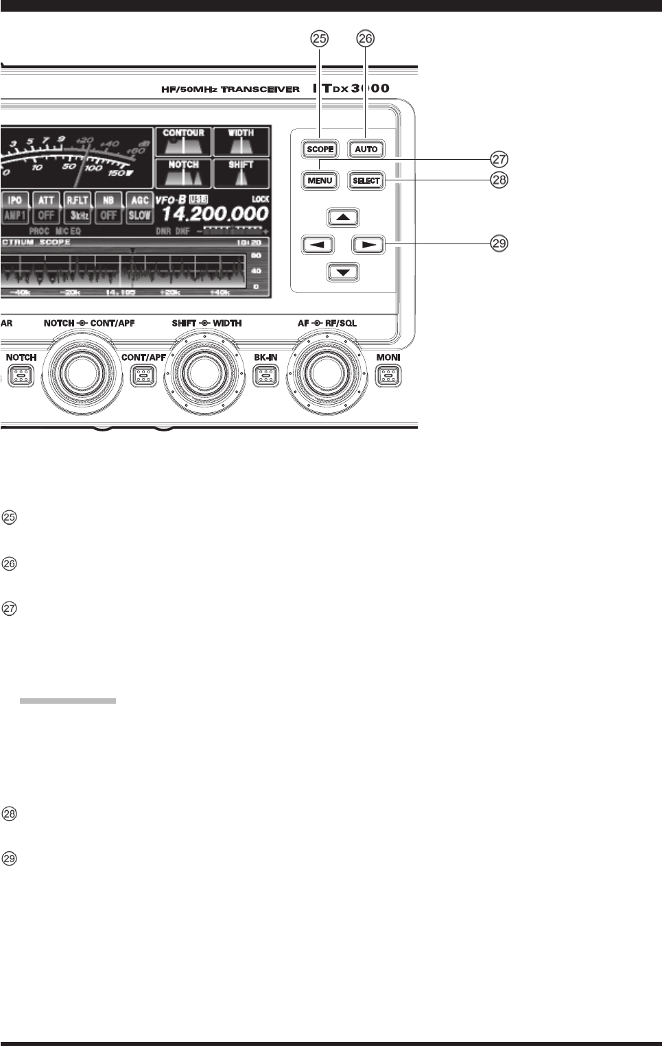
[SCOPE] Switch
T.B.D.
[AUTO] Switch
T.B.D.
[MENU] Switch
ThisbuttonisusedtoaccesstheMenusystem.The
varioustransceiver characteristicsmaybe config-
ured. Menu operation is described in detail, inthis
manual.
ImportaNt Note:
Pressandholdinthe[MENU]switch,activatesthe
Menu. The Menu items will appear on the display;
once you have changed the parameters, you must
pressandholdinthe[MENU]buttonforonesecond
tosaveanycongurationchanges.
[SELECT] Switch
ThisbuttonisusedtoselecttheMenusystem.
[] Switch
ThesebuttonsselectthesettingoftheMenuitem.
FrOnT panel COnTrOls & swiTChes
FCC ID: K6620461X50 / IC: 511B-20461X50
Page 21FT DX 30
00 OperaTing Manual
FrOnT panel COnTrOls & swiTChes
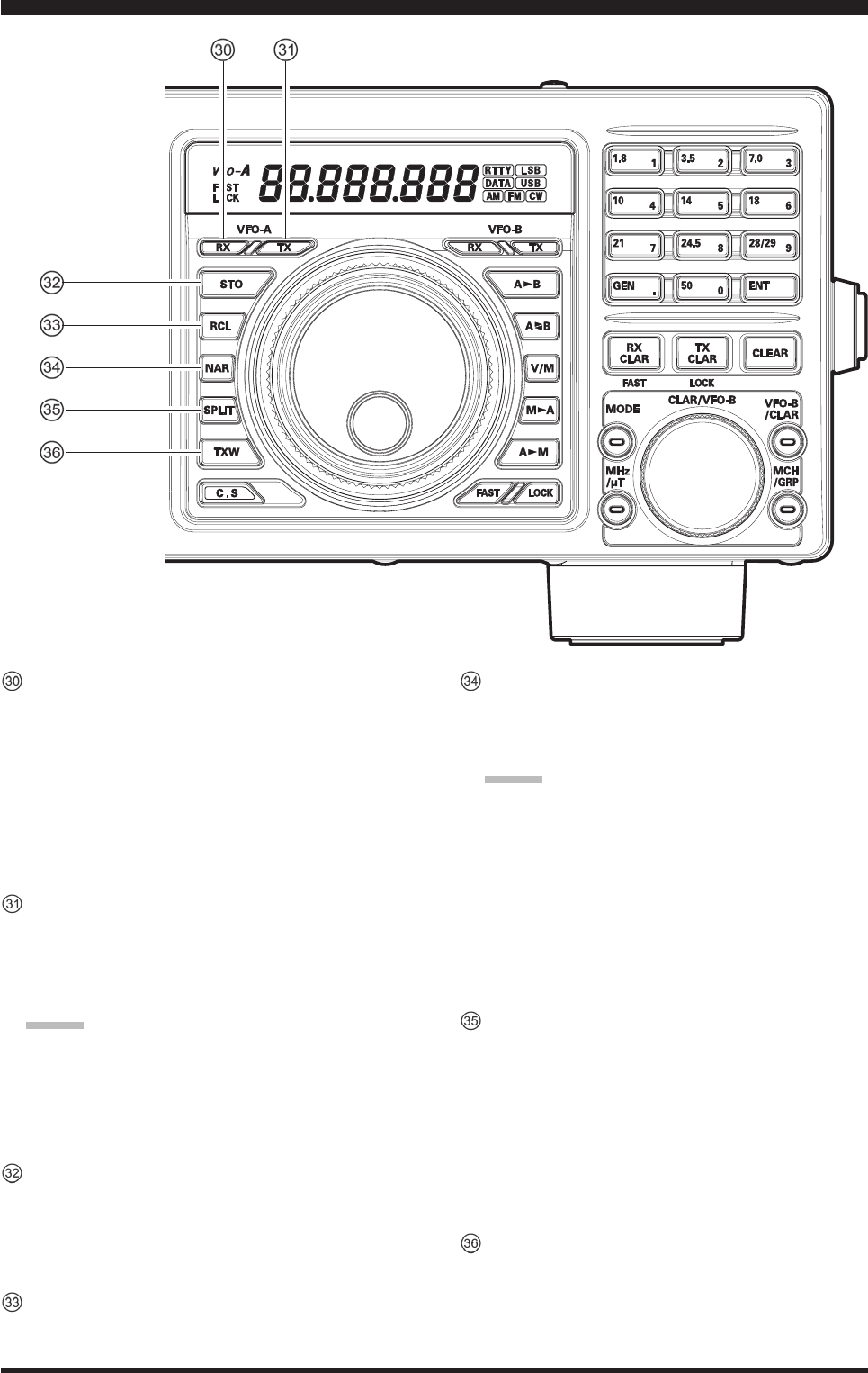
[(VFO-A)RX] Indicator/Switch
PressthisbuttontoactivatereceiveontheVFO-A
frequency.TheLEDinsidethebuttonwillglowgreen
whenthetransceiverreceivestheVFO-Afrequency.
WhenthetransceiverreceivestheVFO-Afrequency,
pressing this button momentarily will mute the re-
ceiver,andtheindicatorwillblink.Pressingthebut-
tononcemorewillrestore receiveroperation,and
theindicatorwillglowgreensteadily.
[(VFO-A)TX] Indicator/Switch
When this button is pushed, the LED inside the
button will glow red; and, when the PTT switch is
pressed,thetransceiverwilltransmitontheVFO-A
frequency(subjecttoanyClarieroffset,ofcourse).
advIce:
Ifthisindicatorisnotilluminated,itmeansthe
[(VFO-B)TX]Indicator/Switch hasbeen selected
(it will be glowing red). In this case, transmission
willbeonthefrequencyandmodeprogrammedfor
VFO-B.
[STO] (Store) Button
Pressing the [STO] button copies the contents (fre-
quency,mode,bandwidth,andalsoFMrepeater
frequency shift/direction and CTCSS functions) of
VFO-A,intoconsecutiveQMBMemories.
[RCL] (Recall) Button
Pressingthe[RCL] button,recallsoneofuptove
QuickMemoryBankmemoriesforoperation.
[NAR] (Narrow) Switch
In the SSB/CW/RTTY/PSK modes, this button is
usedto settheDSP(digital)IFfilterstoNarrow
bandwidth.
advIce:
You may adjust the bandwidth using the [WIDTH]
knob.
In the AM mode, this button is used to toggle the
receiver’sbandwidthbetweenwide(9kHz)andnar-
row(6kHz).
In the FM modeonthe28MHzand50MHzbands,
thisbuttonisusedtotoggletheFMdeviation/band-
widthbetweenwide(±5.0 kHzDev./25.0kHzBW)
andnarrow(±2.5kHzDev./12.5kHzBW).
[SPLIT] Switch
Pressthisbuttontooperatesplitfrequencybetween
VFO-A (usedforreception)andVFO-B(usedfor
transmission).Ifyoupressandholdinthe[SPLIT]
buttonforonesecond,the“QuickSplit”featurewill
be engaged. VFO-B will automatically be set to a
frequency5kHzhigherthantheVFO-A frequency,
withthesameoperatingmode.Thetransceiverwill
beplacedintheSplitmode.
[TXW] (TX Watch) Switch
Pressingthis buttonletsyoumonitorthe transmit
frequencywhensplitfrequencyoperationisen-
gaged. Release the button to return to normal split
frequencyoperation.
FCC ID: K6620461X50 / IC: 511B-20461X50
Page 22 FT DX 30
00 OperaTing Manual
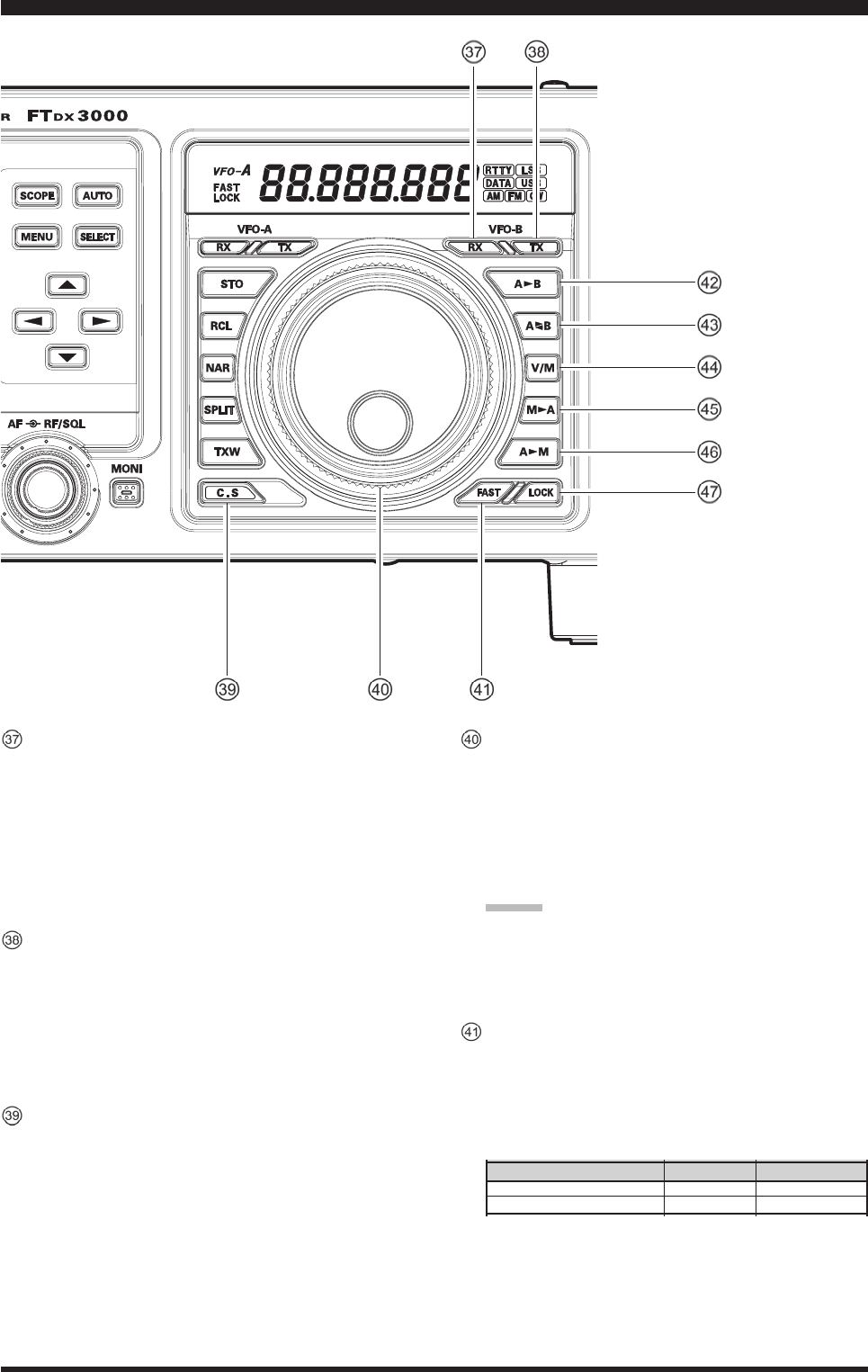
[(VFO-B)RX] Indicator/Switch
Thisbuttonswitchesthereceivingfrequencyto
VFO-B,the greenLED imbeddedwithinthe but-
tonwill light up.When the transceiver receives the
VFO-Bfrequency,pressingthisbuttonmomentarily
will mute the receiver, and the indicator will blink.
Pressing the button once more will restore receiver
operation,andtheindicatorwillglowgreensteadily.
[(VFO-B)TX] Indicator/Switch
Thisbuttontransferscontrolofthetransmitfrequen-
cy/mode to VFO-B, and the red LED in the button
willlightup.Pressingthisbuttonagainwilltransfer
frequency/modecontrolbacktotheVFO-Aside,and
the red LED imbedded within this button will turn
off.
[C.S] Switch
Pressthisbuttonmomentarilytodirectlyrecallafa-
voriteMenuSelection.
To program a Menu selection to the [C.S] button:
pressthe[MENU]buttontoenterthe Menu. Select
theMenuitemyouwanttosetastheshortcut.Then
press and hold in the [C.S] button for one second;
thiswilllockintheselectedMenuitemastheshort
cut.
MainTuningDialKnob
This large knob adjusts the operating frequency of
theVFO-A.Clockwiserotationofthisknobincreas-
es the frequency. Default tuning increments are 10
Hz(100HzinFMmode);whenthe[FAST]button
is pressed, the tuning steps increase.The available
stepsare:
advIce:
ThetuningstepsfortheMainTuningDialknob
areset,at the factory, to 10 Hz perstep.Via Menu
item“150 TUNING DIAL STEP”,however,youmay
changethissettingfrom10Hzto1or5Hzinstead.
[FAST] Switch
Pressing this button will change the tuning rate of
theMainTuningDialknob(VFO-A)to100Hz/step.
Whenthisfunctionisactivated,the“FAST”appears
inthefrequencydisplay.
FrOnT panel COnTrOls & swiTChes
Operating MOde
LSB/USB/CW/RTTY/PKT(LSB)
AM/FM/PKT(FM)
Numbers in parentheses indicate steps when the [FAST] button is On.
1 Step
10 Hz (100 Hz)
100 Hz (1 kHz)
1 dial rOtatiOn
10 kHz (100 kHz)
100 kHz (1 MHz)
FCC ID: K6620461X50 / IC: 511B-20461X50

Page 23FT DX 30
00 OperaTing Manual
FrOnT panel COnTrOls & swiTChes
[A
B] Switch
Pressthisbuttonmomentarilytotransfer thefre-
quency or memory channel data, from VFO-A to
VFO-B,overwritinganypreviouscontentsinVFO-
B.UsethiskeytosetbothVFO-AandVFO-Btothe
samefrequencyandmode.
[A
B] Switch
Pressing this button momentarily, exchanges the
frequency or memory channel data, of VFO-A and
VFO-B.
[V/M] Switch
ThisbuttontogglesfrequencycontrolbetweenVFO-
Aandthememorysystem.Inmemorymode,either
“MCH” (Memory Channel) or “M-TUNE” will be
showntheDisplaytoindicatethecurrentselection.If
youhavetunedthefrequencyofftheMemorychan-
nel, “M-TUNE” will be displayed. Pressing the [V/
M]buttonreturnsthedisplaytotheoriginalmemory
frequency, and the “MCH”willagain be displayed.
Pressingitoncemorereturnsfrequencyoperationto
theVFO-A,andtheiconwillnolongerbedisplayed.
[M
A] Switch
Pressingthis buttonmomentarily,will displaythe
contents of the currently-selected memory channel
for10seconds.
Holding[M
A]buttoninforonesecondcopiesthe
datafrom the selected memory toVFO-A,andtwo
beepssound.PreviousdatainVFO-A will be over-
written.
[A
M] Switch
Pressing this button momentarily, displays the con-
tents of the currently-selected memory channel for
10seconds.
Pressingandholdinginthiskeyforonesecond(until
the double beep) copies the current operating data
intothecurrentlyselectedmemory channel,over-
writinganypreviousdatastoredthere.
[LOCK] Switch
Thisbuttontoggleslockingon/offfortheMainTun-
ingDialknob(VFO-A).With “Lock” on, the Main
TuningDial knobcan stillbe turned,but thefre-
quencywillnotchange,andthe“LOCK”appearsin
thefrequencydisplay.
[BAND] Keys
Thesekeysallowone-touchselectionofthedesired
Amateurband(1.8~50MHz).
Thekeysmayalsobeusedfordirectentryofade-
siredoperatingfrequencyduringVFOoperation.
FCC ID: K6620461X50 / IC: 511B-20461X50
Page 24 FT DX 30
00 OperaTing Manual
FrOnT panel COnTrOls & swiTChes
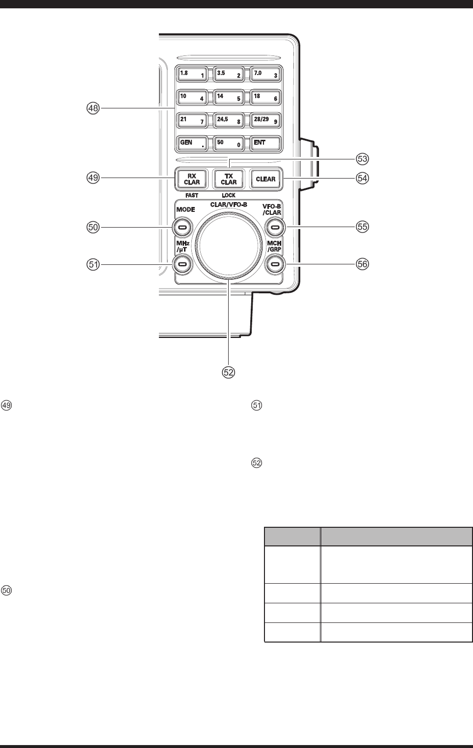
[RXCLAR] Switch
PressingthisbuttonactivatestheRXClarier.This
willallow youtotemporarilyadjustthereceiving
frequency up to ±9.99 kHz with the [CLAR/VFO-
B] knob. Press this button once more to return the
receivertotheoriginalfrequency;theClarieroffset
willberemembered,incaseyouwanttouseitagain.
To cancel the Clarifier offset, press the [CLEAR]
button.
Press the [VFO-B/CLAR] button followed by this
switchwillchangethetuningrateoftheMainTun-
ingDialknob(VFO-B)to100Hz/step.
Whenthisfunctionisactivated,the“FAST”appears
inthefrequencydisplay.
[MODE] Switch
This button selects the operating mode. The selec-
tionsavailableare:
LSBàCW(USB)àRTTY(LSB)à
àDATA(LSB)àAMàLSBà
Repeatedpressesthisbutton,stepthroughtheavail-
ableselections.
Pressand hold in the this button, will toggle to the
alternatemode.
Forexample,In the LSB or USB modes,pressand
hold in the this button toggles between “LSB” and
“USB”mode.
[MHz/µT] Switch
PressingthisbuttonallowsyoutotunetheVFOfre-
quencydownorupin1MHzincrements,usingthe
[CLAR/VFO-B]knob.
[CLAR/VFO-B] Knob
ThisknobusuallytunestheClarieroffsetfrequency
up to ±9.999 kHz.Additionally, it is used to adjust
thefunctionsselectedwithfivebuttonslocated
aroundtheknob.
effect
Rotate the [CLAR/VFO-B] knob to adjust
the VFO-B frequency, in the same step
as the Main Tuning Dial knob.
Rotate the [CLAR/VFO-B] knob to select
the memory group.
Rotate the [CLAR/VFO-B] knob to tune
the VFO frequency in 1 MHz step.
Rotate the [CLAR/VFO-B] knob to select
the memory channel.
fuNctIoN
SwItch
[(VFO-B)RX]
[GRP]
[MHz]
[MCH]
FCC ID: K6620461X50 / IC: 511B-20461X50

Page 25FT DX 30
00 OperaTing Manual
FrOnT panel COnTrOls & swiTChes
[TXCLAR] Switch
PressingthisbuttonactivatestheTXClarier,toal-
low offsetting the transmit frequency temporarily.
Press this button once more to return the transmit-
tertotheoriginalfrequency;theClarifieroffset
will be remembered, though, in case you want to
useitagain.TocanceltheClarieroffset,pressthe
[CLEAR]button.
Press the [VFO-B/CLAR] button followed by this
switchtoggleslockingon/offfortheCLAR/VFO-B
knob(VFO-B).With“Lock”on,theCLAR/VFO-B
knob can still be turned, but the frequency will not
change,andthe“LOCK”appearsinthedisplay.
[CLEAR] Switch
Pressing this button clears out any frequency offset
youhaveprogrammedintotheClarifierregister
(therebysettingtheoffsetto“Zero”).
[VFO-B/CLAR] Switch
Pressing this button clears out any frequency offset
youhaveprogrammedintotheClarifierregister
(therebysettingtheoffsetto“Zero”).
[MCH/GRP] Switch
MCH
Pressingthisbuttonallowsyoutoselectthememory
channelusingthe[CLAR/VFO-B]knob.
GRP
Pressingthisbuttonallowsyoutoselectthememory
groupbyturningthe[CLAR/VFO-B]knob.
FCC ID: K6620461X50 / IC: 511B-20461X50
Page 26 FT DX 30
00 OperaTing Manual
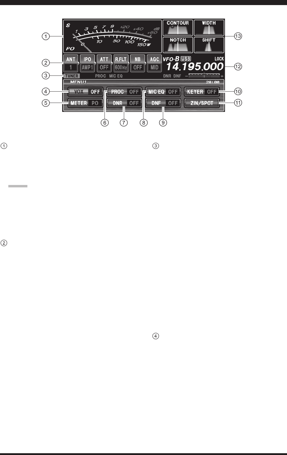
S/PO
Onreceive,thisindicatesthereceivedsignal
strength,fromS-0toS-9+60dBonreceiving.
Ontransmit,itindicatestheRFPowerOutput,from
0to150Wattsontransmit.
advIce:
TheSandPOmetertypescanbechangetheANA-
LOGorBAR typeviathe Menuitems“012 DIS-
PLAY METER TYPE SELECT”.
TheS andPOmeters canbeset tothePeak-hold
function(BARtypeonly)viatheMenuitems“013
DISPLAY BAR MTR PEAK HOLD”.
BlockDiagramDisplay
ANT(1,2,3):
Indicatestheantennaselectedbythefrontpanel
[ANT]button.
IPO(AMP1,AMP2,IPO):
IndicateswhichfrontendRFamplierisselectedby
thefrontpanel[IPO]button.
ATT(OFF,–6dB,–12dB,–18dB):
Indicatestheattenuationlevel,selectedbythefront
panel[ATT]button.
R.FLT(3kHz,6kHz,15kHz):
IndicatesthereceiverIFRoongFilter,whichisse-
lectedbythefrontpanel[R.FLT]button.
NB(OFF,ON,ON(NBW)):
Indicatesthereceiver’s“short-duration”Noise
Blanker, which is selected by the front panel [NB]
button.
AGC(SLOW,FAST,MID):
IndicatestheAGCdecaytime setting,selectedby
thefrontpanel[AGC]switch.
Display inDiCaTiOns (leFT siDe)
CongurationIndicators
TUNER
This indicator appears when the internalAutomatic
AntennaTunerisactivated.
VOX
Thisindicatorappears whentheautomaticvoice-
actuatedtransmitterswitchingtheSSB,AM,andFM
modes.
KEYER
This indicator appears whenever the internal CW
keyerisactivated.
PROC
Thisindicatorappears wheneverthe DSPSpeech
Processorisactivated.
MICEQ
This indicatorappearswhenever theThree-Band
ParametricMicrophoneEqualizerisactivatedviathe
Menu.
DNR
This indicator appears whenever the DigitalNoise
Reductionfeatureisactivated.
DNF
This indicator appears whenever the Digital Notch
Filterisactivated.
[VOX] Indicator
Thisindicatorenablesautomaticvoice-actuated
transmitter switching in the SSB,AM, and FM
modes. While activated, the LED inside this button
glowsred.ThecontrolsaffectingVOXoperationare
the Menu items “114 TGEN V GAIN”, “115 TGEN
VOX DLY”,and“116 TGEN ANTI VOX”. Byproper
adjustmentof these controls, hands-freevoice-actu-
atedoperationispossible.
FCC ID: K6620461X50 / IC: 511B-20461X50
Page 27FT DX 30
00 OperaTing Manual
Display inDiCaTiOns (CenTer)
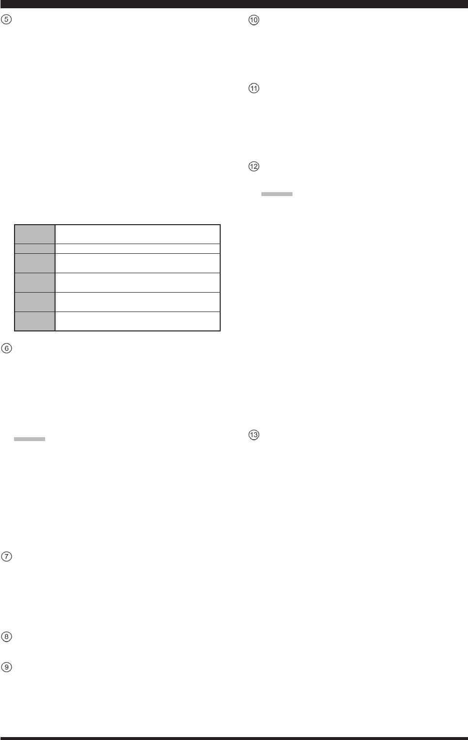
[METER] Indicator
This indicator determines the function of the meter
duringtransmission.
Pressthisbuttontochangethemeterfunctioninthe
transmitmodeasfollows:
PO ALC SWR COMP
ID VDD PO……
PO: Indicates the RF Power Output, from 0 to
150Wattsontransmit.
ALC: IndicatestherelativeALCvoltage.
SWR: IndicatestheStandingWaveRatio(Forward/
Reected).
COMP: Indicatesthespeechcompressorlevel(SSB/
AMmodesonly).
ID: Indicatesthenalamplierdraincurrent.
VDD: Indicatesthenalamplierdrainvoltage.
Indicates the RF Power Output, from 0 to 150
Watts on transmit.
Indicates the relative ALC voltage.
Indicates the Standing Wave Ratio
(Forward: Reected), from 1.0 to 3.0.
Indicates the speech compressor level,
from 0 to 30 dB.
Indicates the nal amplier drain current,
0 to 30 ampere.
Indicates the nal amplier drain voltage
(nominal value: 13.8 V).
PO
ALC
SWR
COMP
ID
VDD
[PROC] (Processor) Indicator
Thisindicator enablesthe ParametricMicrophone
Equalizer and Speech Processorfor SSBtransmis-
sion.WhentheParametric MicrophoneEqualizer
isactivated.Adjustmentofthe Processorlevelis
accomplished via the Menu item “109 TGEN PRO-
CLVL”.
advIce:
The Speech Processor is a tool for increasing
the averagepoweroutputthrougha compres-
sion technique. However, if the Processor level
isadvancedtoofar, the increase in compression
becomescounter-productive,asintelligibility
willsuffer.Werecommendthatyou monitorthe
soundofyoursignalusing theMonitor(with
headphones).
[DNR] Indicator
This indicator turns the Main band (VFO-A) re-
ceiver’sDigitalNoiseReductioncircuitonand
off.Adjustment of the Noise Reduction level is ac-
complishedviatheMenuitem“111 RX DSP DNR
LEVEL”.
[MICEQ] switch
Thisindicator
[DNF] Indicator
ThisindicatorturnstheMainband(VFO-A)receiv-
er’sDigitalNotchFilteronandoff.Thisisanauto-
maticcircuit,andthereisnoadjustmentknobforthe
DNF.
[KEYER] Indicator
ThisindicatortogglestheinternalCWkeyeronand
off.TheKeyersendingspeedisadjustedviathe
frontpanel’s[SPEED]knobandtheCWHangTime
isadjustedviatheMenuitem“044 A1A DELAY”.
[ZIN/SPOT] Indicator
This indicatorenablesthetheCWreceiverspot-
tingtone;bymatchingtheSPOTtonetothatofthe
incomingCWsignal(preciselythesamepitch),you
will be “zero beating” your transmitted signal with
thefrequencyoftheotherstation.
Sub(VFO-B)FrequencyDisplay
ThisistheSubband(VFO-B)frequencydisplay.
advIce:
Whenturningthe[CLAR],[PITCH],[SPEED],
[CONTOUR], [NOTCH], [DNR], [DELAY],
[CARRIER], [MIC], [PROC], [SHIFT], or
[WIDTH]knob,eachfrequencyorvaluewillap-
pearinthisareafor3seconds.
If the knob is turned too slowly, the frequency
display may not show the value. This is to pre-
vent undesired display of the functions caused
by noise or slight vibration of the controls;
however, the actual value will be changed even
if not displayed.
You can observe the ne adjustment for a few
seconds while the display is active.
While adjusting functions, the display may oc-
casionally skip one of the numbers in the se-
quence; this is due to “rounding” of the encoder
steps in the ADC converter. Set the values to
your preference, they are unique to your radio
and may not directly correspond to other units.
DSPDisplay
T.B.D.
FCC ID: K6620461X50 / IC: 511B-20461X50
Page 28 FT DX 30
00 OperaTing Manual
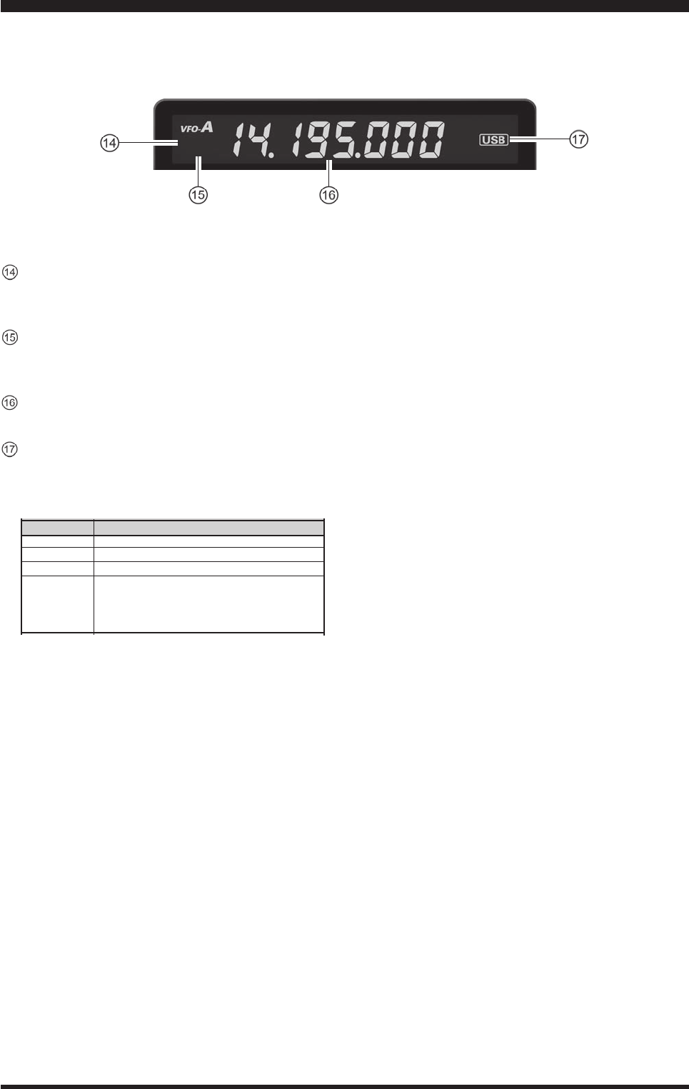
Display inDiCaTiOns (righT siDe)
[FAST] Indicator
This indicator appears when the MainTuning Dial
knob’s,tuningrateissetto“fast”.
[LOCK] Indicator
This indicator appears when the MainTuning Dial
knobislocked.
FrequencyDisplay
Thisisthefrequencydisplay.
LSB,USB,CW,AM,FM,RTTY,DATA
Displaysthecurrentoperatingmode.
SwItch
[SSB]
[CW]
[AM/FM]
[RTTY/PKT]
varIable mode SelectIoNS
LSB USB
CW(LSB) CW(USB)
AM FM
Momentarily: RTTY(LSB) PKT(LSB)
Press & Hold: RTTY(LSB) RTTY(USB) or
DATA(LSB) DATA(USB)
PKT(FM) PKT(LSB) ....
FCC ID: K6620461X50 / IC: 511B-20461X50