Yaesu Musen 20461X50 Scanning Receiver User Manual FTDX3000 Operating Manual
Yaesu Musen Co., Ltd. Scanning Receiver FTDX3000 Operating Manual
Contents
Users Manual 5
Page 40 FT DX
3000 OperaTing Manual
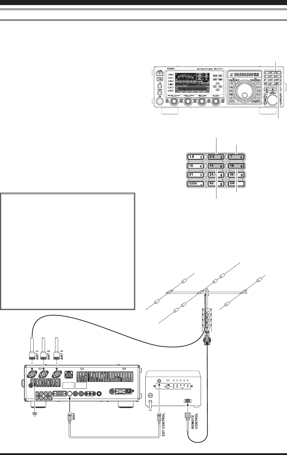
RotAtoR coNtRol FuNctioNs
When using a YAESU model G-800DXA, G-1000DXA, G-2800DXA Antenna Rotator (not supplied), it is possible to
control it from the front panel of the FT DX 3000.
1. Press and hold in the [ENT] button (one of the
[BAND] key switches) for one second. The Fre-
quency Display area will change over to the “Rotator
Control” conguration.
2. Press either the [3.5(2)] button or the [7(3)] button
to rotate the antenna. Pressing the [3.5(2)] button
will cause rotation to the left (counter-clockwise) by
two degree steps, while pressing the [7(3)] button
will cause rotation to the right (clockwise) by two
degree steps.
3. Press the [14(5)] button or the [18(6)] button to con-
trol the speed of rotation. Pressing the [14(5)] button
will cause slower rotation, while pressing the [18(6)]
button will speed up rotation. Usually, you will be
using the “100%” speed setting.
When you are through exercising rotator control, press
the [ENT] button momentarily. The Frequency Display
will return to the main display eld.
iMpoRtANt Note
Set the starting point to match your rotator
control indicator needle via the Menu item
“014 DISPLAY ROTATOR START UP”. The
default setting is zero (north). If your control-
ler starting point is south, the Menu item “014
DISPLAY ROTATOR START UP” must be set
to “180”. If not set properly the FT DX 3000
display will not show the correct direction.
When the rotator control indicator needle
does not indicate the precise antenna direc-
tion, calibrate the indicator needle precisely
to the antenna direction via the Menu item
“015 DISPLAY ROTATOR OFFSET ADJ”.
cOnvenience FeaTures
[3.5(2)], [7(3)] Button
[14(5)], [18(6)] Button
[ENT] Button
Counter-clockwise Rotation
Clockwise Rotation
Speed Down
Speed Up
Remove the rubber cap rst,
and then connect the plug.
FCC ID: K6620461X50 / IC: 511B-20461X50
Page 41FT DX
3000 OperaTing Manual
MoRe FReQueNcy NAvigAtioN tecHNiQues
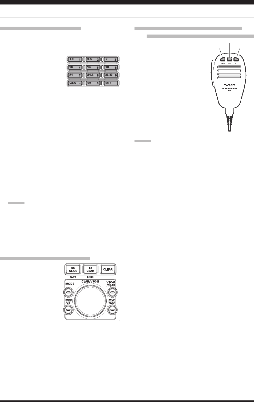
cOnvenience FeaTures
[DWN] Button
[FST] Button
[UP] Button
Keyboard Frequency Entry
You may enter operating frequencies directly into the
current VFO, using the front panel [BAND] key buttons.
Example: Enter 14.250.00 MHz
1. Pr e s s th e [ENT] but-
ton to engage the direct
frequency entry process.
Now, beginning with the
rst digit of the frequency
(the leftmost digit), we will enter the required digits
of the frequency.
2. Press, in order, the digits of the operating frequency,
using the [BAND] buttons (the frequency entry digit
or decimal point is printed on the right side of the
buttons). In this example, enter
[1.8(1)] [10(4)] [GEN(.)] [3.5(2)]
[14(5)] [50(0)] [50(0)] [50(0)]
[50(0)]
The decimal point after the “MHz” portion of the
frequency must be entered, but no decimal point is
required after the “kHz” portion.
3. Press the [ENT] button once more. A short “beep”
will conrm that the frequency entry was successful,
and the new operating frequency will appear on the
display.
Advice:
If you attempt to enter a frequency outside the oper-
ating range of 30 kHz ~ 56 MHz, the microprocessor
will ignore the attempt, and you will be returned to
your previous operating frequency. If this happens,
please try again, taking care not to repeat the error in
the frequency entry process.
Using the [CLAR/VFO-B] knob
You may change the cur-
rent VFO frequency in 1
MHz steps. Press the [MHz]
button located at the bot-
tom and left of the [CLAR/
VFO-B] knob. The 1 MHz
steps will be applied to the
current VFO frequency.
The imbedded LED in the
[MHz] button will glow orange in the latter case.
When tuning in 1 MHz steps, clockwise rotation of the
[CLAR/VFO-B] knob will increase the frequency, while
counter-clockwise rotation will decrease the frequency.
Using the [UP]/[DWN] buttons of the
supplied MH-31B8 Hand Microphone
The [UP]/[DWN] buttons on
the supplied MH-31B8 Hand
Microphone may also be used
to manually scan the frequency
upward or downward.
The microphone’s [UP]/[DWN]
buttons utilize the tuning steps of
the Main Tuning Dial knob.
When the microphone’s [FST] button
is pressed, the tuning rate increases
by a factor of ten, in a manner similar
to the transceiver front panel [FST]
button.
Advice:
You may independently set the tuning steps of the [UP]/
[DWN] buttons in the AM and FM modes. To set new
tuning steps, use Menu items “154 TUNING AM CH
STEP” and “155 TUNING FM CH STEP”.
FCC ID: K6620461X50 / IC: 511B-20461X50

Page 42 FT DX
3000 OperaTing Manual
ReceiveR opeRAtioN (FRoNt eNd blocK diAgRAM)
The FT DX 3000 includes a wide range of special features to suppress the many types of interference that may be en-
countered on the HF bands. However, real world interference conditions are constantly changing, so optimum setting of
the controls is somewhat of an art, requiring familiarity with the types of interference and the subtle effects of some of
the controls. Therefore, the following information is provided as a general guideline for typical situations, and a starting
point for your own experimentation.
The FT DX 3000’s interference-ghting circuitry begins in its “RF” stages, and continues throughout the entire receiver
section. FT DX 3000 allows conguration of the features described below.
R. FLT (IF Roong Filters)
Three Roofing filters, of 15 kHz, 6 kHz, and 3 kHz
bandwidths, are provided in the 69 MHz First IF, right
after the rst mixer. These lters are automatically se-
lected to provide narrow-band selectivity to protect the
following IF and DSP stages. The automatically selected
lter, may be manually changed by the operator, if de-
sired, for special operating circumstances.
CONTOUR Filter
The DSP Contour filter has the unique ability to pro-
vide either a null or a peak in tunable segments of the
receiver passband. You may suppress interference and
excessive frequency components on an incoming signal,
or you may peak those tunable frequency segments. The
level of the null or peak, and the bandwidth, over which
it is applied, are adjustable via the Menu.
IF SHIFT
The passband center frequency of the IF DSP lter may
be moved up or down by adjusting this control.
IF WIDTH
The width of the IF DSP ltering may be adjusted using
this control.
IF NOTCH
The IF Notch lter is a high-Q notch lter that can sig-
nicantly reduce, if not eliminate, an interfering carrier.
DNF (Digital Notch lter)
When multiple interfering carriers are encountered dur-
ing reception, the Digital Notch Filter can signicantly
reduce the level of these signals.
DNR (Digital Noise Reduction)
The DSP’s Digital Noise Reduction (DNR) feature uti-
lizes 15 different mathematical algorithms to analyze
and suppress different noise proles encountered on the
HF/50 MHz bands. Choose the selection that provides
the best noise suppression, and allows the signal to rise
up out of the noise.
AGC
The AGC system is highly adaptable to changing signal
and fading characteristics, making reception possible
under the most difcult conditions.
inTerFerence rejecTiOn
FCC ID: K6620461X50 / IC: 511B-20461X50
Page 43FT DX
3000 OperaTing Manual
Block Diagram Display
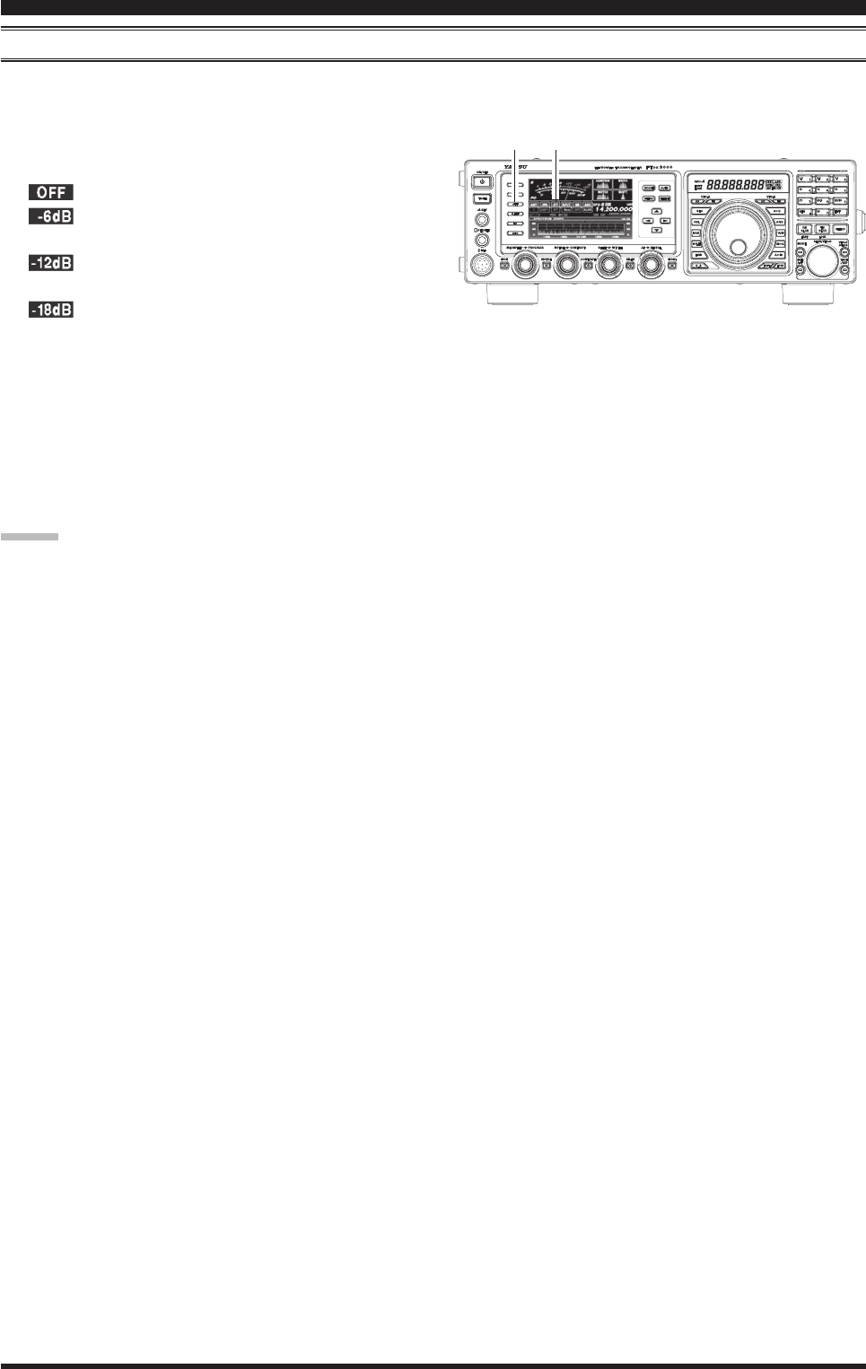
inTerFerence rejecTiOn
ATT
When extremely strong local signals or high noise, still degrades reception, you can use the [ATT] button to insert 6, 12,
or 18-dB of RF attenuation in front of the RF amplier.
1. Press the [ATT] button several times to set the de-
sired attenuation level, per the chart below.
: Attenuator is Off
: The incoming signal power is reduced by 6
dB (Signal voltage reduced by 1/2)
: The incoming signal power is reduced by 12
dB (Signal voltage reduced to 1/4)
: The incoming signal power is reduced by 18
dB (Signal voltage reduced to 1/8th)
The selected attenuation level will be indicated in the
ATT column of the Block Diagram Display on the
display.
2. To restore full signal strength through the Attenua-
tor circuit area, press the [ATT] button to restore the
ATT display to the “OFF” position.
Advice:
The attenuator selection will be memorized independently on each VFO stack of the VFO-A and VFO-B.
If background noise causes the S-meter to deect on clear frequencies, press the [ATT] button until the S-meter
drops to about “S-1”. This setting optimizes the trade-offs between sensitivity, noise, and interference immunity.
Also, once you have tuned in a station you want to work, you may want to reduce sensitivity further (add more at-
tenuation) by pressing the [ATT] button to a higher setting. This reduces the strength of all signals (and noise) and
can make reception more comfortable, important especially during long QSOs. When looking for weak signals on a
quiet band, you will want maximum sensitivity, so the IPO should be disabled and the [ATT] button should be set to
“OFF.” This situation is typical during quiet times on frequencies above 21 MHz, and when using a small or nega-
tive-gain receiving antenna on other bands.
[ATT] Button
FCC ID: K6620461X50 / IC: 511B-20461X50
Page 44 FT DX
3000 OperaTing Manual
µ-tuNe FilteR (ReQuiRes tHe optioNAl RF µtuNiNg Kit)
The RF µTuning Kit provides ultra-sharp RF selectivity for the front end of the transceiver. Very high Q is made pos-
sible by the narrow-band design. Three RF µTuning Kits are available. The MTU-160 covers the 1.8 MHz band. The
MTU-80/40 covers the 3.5 and 7 MHz bands. The MTU-30/20 covers 10.1 and 14 MHz bands.
When any (or all) of the three optional units are connected, they will be automatically adjusted to center on your operat-
ing frequency.
The narrow bandwidth is especially useful on the low bands, when many strong signals are being received via NVIS
propagation (Near Vertical-Incidence Signals) within a narrow bandwidth. The added protection for the RF stage is es-
pecially helpful in preventing IMD and blocking.
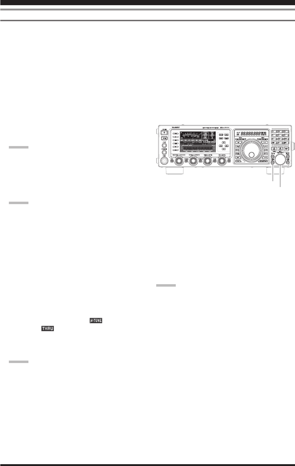
µ-Tune Operation
1. Press the [MHz/µT] button to activate the µ-Tune
filter. The LED inside the [MHz/µT] button glows
orange. The [CLAR/VFO-B] knob works as the
µ-TUNING knob.
Advice:
The µ-Tune circuit will automatically align itself
onto your operating frequency.
Remember that µ-Tune only operates on the 14
MHz and lower bands.
2. Rotate the [CLAR/VFO-B] knob to peak the re-
sponse (background noise) or reduce interference.
Advice:
You may observe the relative peak point of the
µ-Tune filter in the Tuning Offset Indicator on
the display, while tuning the [CLAR/VFO-B]
knob.
The amount of change in the center frequency
of the µ-Tune filter, when rotating the [CLAR/
VFO-B] knob by one click, can be configured
using Menu item “045 GENERAL µTUNE DIAL
STEP”.
If you have performed manual adjustment of the
µ-Tune lter center frequency, you may press the
[CLAR/VFO-B] button to re-center the lter re-
sponse on your current operating frequency.
3. Press the [MHz/µT] button momentarily to dis-
engage the µ-Tune filter; the “ ” icon will be
changed to “ ” in the FLT column of the Block
Diagram Display on the display. In this mode, only
the xed bandpass lter for the current band will be
engaged.
Advice:
Alternate presses of the [MHz/µT] button, will
switch the µ-Tune lter between on or off.
inTerFerence rejecTiOn
[MHz/µT] Button
[CLAR/VFO-B] Button
Advice:
The µ-Tune Filter selection will be memorized in-
dependently on each VFO stack of the VFO-A and
VFO-B.
You may change the indication of the Tuning Offset
Indicator to display of the µ-Tune lter continuously
while the µ-Tune filter is activated. This is Menu
item “011 DISPLAY BAR DISPLAY SELECT”. See
Box on the next page for details of the setting.
FCC ID: K6620461X50 / IC: 511B-20461X50