Yaesu Musen 20461X50 Scanning Receiver User Manual FTDX3000 Operating Manual
Yaesu Musen Co., Ltd. Scanning Receiver FTDX3000 Operating Manual
Contents
Users Manual 7
Page 49FT DX
3000 OperaTing Manual
inTerFerence rejecTiOn
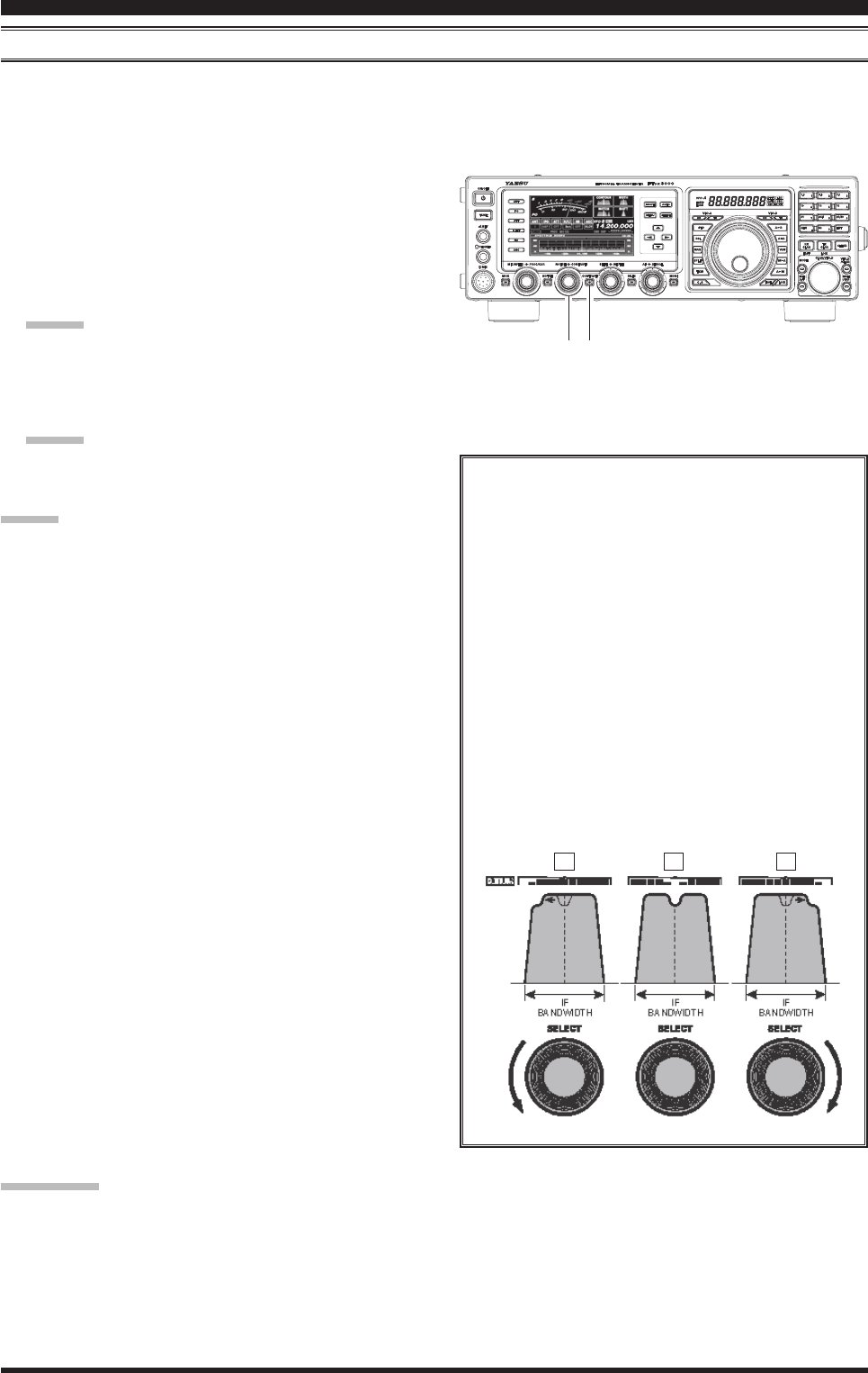
coNtouR coNtRol opeRAtioN
The Contour ltering system provides a gentle perturbation of the IF lter passband. The Contour is set to either sup-
press, or boost specic frequency components, and thus enhance the sound and readability of a received signal.
1. Press the [CONT/APF] button to activate the Con-
tour lter. The LED inside the [CONT/APF] button
glows orange and the current “null” (or “peak”) po-
sition of the Contour lter will appear in the CON-
TOUR indicator on the display.
2. Rotate the [CONT/APF] knob to achieve the most
natural-sounding audio reproduction on the incom-
ing signal.
Advice:
The display will show the Contour frequency for 3
seconds whenever the [CONT/APF] knob is turned.
3. To cancel Contour tuning, press the [CONT/APF]
button momentarily.
Advice:
Alternate presses of the [CONT/APF] button, will
switch the Contour lter between on or off.
Advice:
The Contour lter selection will be memorized inde-
pendently on each VFO stack of VFO-A and VFO-B.
The Contour lter level (either a null or a peak) may
be adjusted using Menu item “109 RX DSP CON-
TOUR LEVEL”. The factory default setting is for a
null of –15 (dB).
The bandwidth over which the Contour lter effect is
applied may be adjusted using Menu item “110 RX
DSP CONTOUR WIDTH”. The factory default setting
is 10.
When the optional DMU-2000 Data Management
Unit is connected, the Audio Scope (on the “Oscil-
loscope” page) is particularly useful when adjusting
the Contour control. Not only can you see the effect
of the null/peak of the Contour system, but you also
can see the position of the null/peak with respect to
frequency components of interest on the incoming
signal. You may then observe (on the Audio Scope)
the effect of the Contour control while listening to
the effect on the signal, and this will help build your
intuition on how best to use Contour tuning in the
future.
Refer to Figure “B”, this illustrates an “indenta-
tion” of the Contour filter in the center of the
passband. The Contour lter is placing a low-Q
“notch” (per the setting of Menu item “069
RGEN CNTR LV”, referenced above) in the pass-
band. Counter-clockwise rotation (to the left)
of the [CLAR/VFO-B] knob causes the notch
to move towered a lower frequency within the
passband, while clockwise rotation (to the right)
causes the notch to move toward a higher fre-
quency within the passband. By removing inter-
ference or unwanted frequency components of
the incoming signal, it is possible to make the
desired signal rise out of the background noise/
interference, enhancing intelligibility.
QuicK poiNt:
The steep slopes of the DSP ltering, when adjusted aggressively, can impart an unnatural sound to an incoming sig-
nal. Often, a narrow bandwidth is not the key to improving copy; the incoming signal itself may have undesirable or
excessive frequency components, especially in the low frequency range around 100-400 Hz. By judicious use of the
Contour lter, the “shoulder” of the passband response may be altered, or components may be removed from within the
passband, allowing the desired signal to rise above the background noise and interference in a manner not obtainable
with other ltering systems.
[CONT/APF] Button
[CONT/APF] Knob
A B C
FCC ID: K6620461X50 / IC: 511B-20461X50
Page 50 FT DX
3000 OperaTing Manual
inTerFerence rejecTiOn
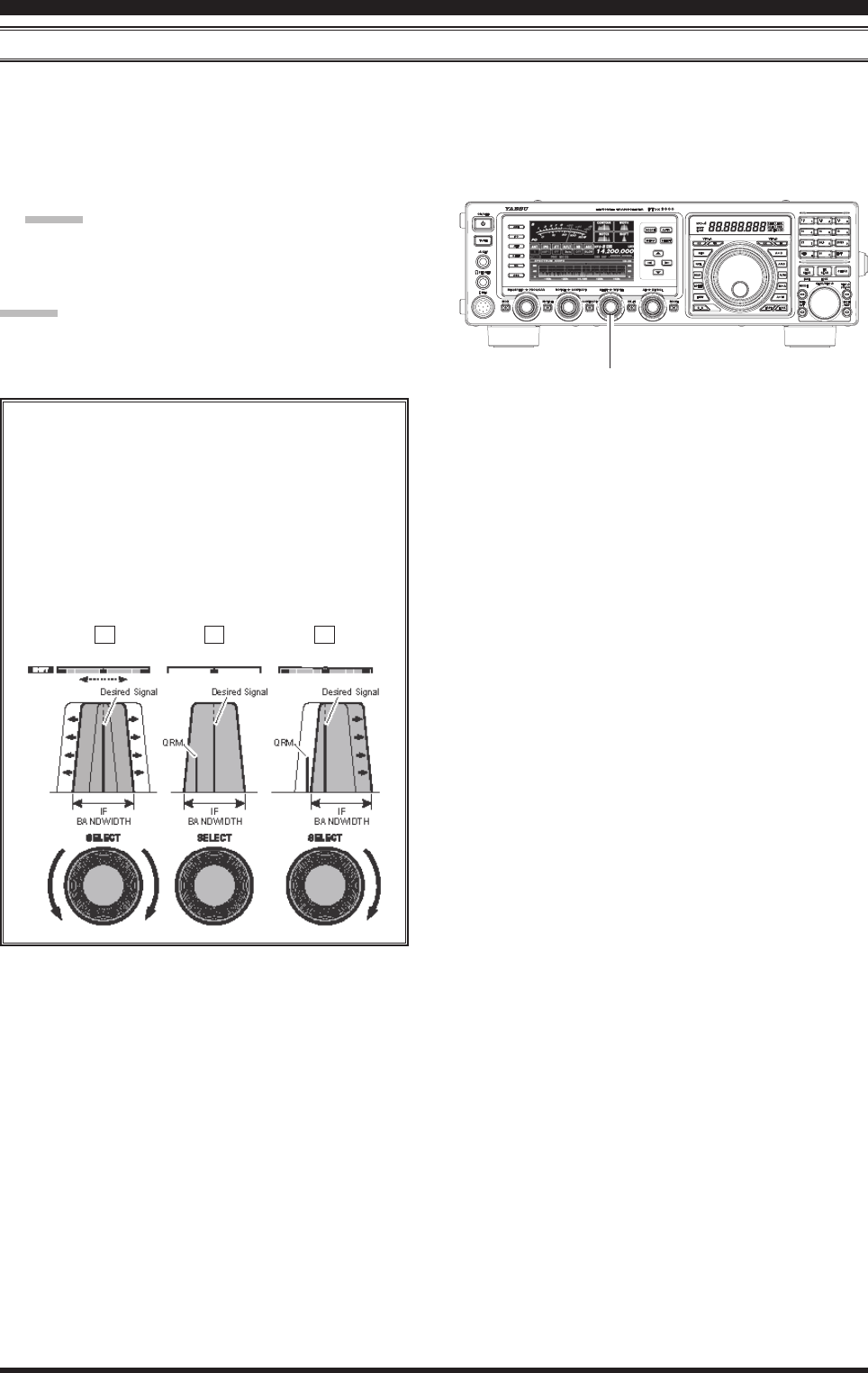
iF sHiFt opeRAtioN (ssb/cw/Rtty/pKt/AM Modes)
IF SHIFT allows you to move the DSP lter passband higher or lower, without changing the pitch of the incoming sig-
nal, and thus reduce or eliminate interference. Because the carrier tuning frequency is not varied, there is no need to re-
tune the operating frequency to eliminate the interference. The total passband tuning range for the IF SHIFT system is
±1 kHz.
1. Rotate the [SHIFT] knob to the left or right to re-
duce the interference.
Advice:
The display will show the shift value of the IF
SHIFT for 3 seconds whenever the [SHIFT] knob is
turned.
Advice:
The center position of the IF passband will be memo-
rized independently on each VFO stack of VFO-A and
VFO-B.
Referring to Figure “A”, note the depiction of the
IF DSP lter as the thick line, with the [SHIFT]
knob in the 12 o’clock position. In Figure “B”, an
interfering signal has appeared inside the original
passband. In Figure “C”, you can see the effect
of rotating the [SHIFT] knob. The interference
level is reduced by moving the lter passband so
that the interference is outside of the passband.
[SHIFT] Knob
A B C
FCC ID: K6620461X50 / IC: 511B-20461X50
Page 51FT DX
3000 OperaTing Manual
inTerFerence rejecTiOn
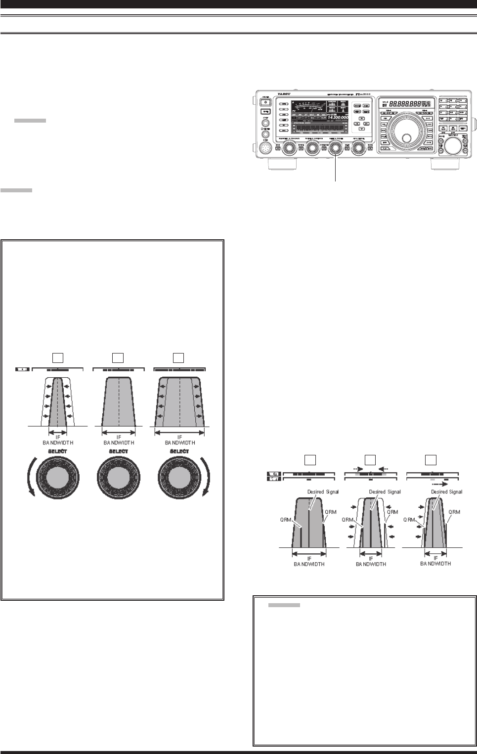
widtH (iF dsp bANdwidtH) tuNiNg (ssb/cw/Rtty/pKt Modes)
The IF WIDTH tuning system allows you to vary the width of the DSP IF passband, to reduce or eliminate interference.
Moreover, the bandwidth may actually be expanded from its default setting, should you wish to enhance incoming sig-
nal delity when interference on the band is low.
1. Rotate the [WIDTH] knob to the left or right to re-
duce the interference.
Advice:
The frequency display will show the bandwidth of
the IF passband for 3 seconds whenever the [WIDTH]
knob is turned.
[WIDTH] Knob
Advice:
The IF Bandwidth will be memorized independently on
each VFO stack of VFO-A and VFO-B.
Referring to Figure “B”, you can see the default
bandwidth on the SSB mode.
By rotating the [WIDTH] knob to the left, the
bandwidth will narrow (see Figure “A”, while
rotation of the [WIDTH] knob to the right, as
depicted in Figure “C”, will increase the band-
width.
A B C
The default bandwidths, and total bandwidth ad-
justment range, will vary according to the operat-
ing mode:
SSB Mode: 1.8 kHz ~ 4.0 kHz (default: 2.4 kHz).
CW Mode: 500 Hz ~ 2.4 kHz (default: 2.4 kHz)
RTTY/PKT Modes: 500 Hz ~ 2.4 kHz (default:
500 Hz)
UsingIFSHIFTandWIDTHTogether
The IF SHIFT and Variable IF WIDTH features
together form a very effective interference-ght-
ing ltering system.
For example, in Figure “A”, you can see how in-
terference has appeared both on the high and low
sides of the desired signal. Rotate the [WIDTH]
knob, the interference from one side can be
eliminated (Figure “B”). Next, rotate the [SHIFT]
knob to re-positioning the passband (Figure “C”),
the interference on the opposite side can be re-
moved, without re-introducing the interference
previously eliminated in Figure “B”.
A B C
Advice:
For best interference reduction, the WIDTH and
SHIFT features are the primary tools you should
use. After narrowing the bandwidth (WIDTH)
and/or adjusting the center of the passband
(SHIFT). The Contour control may then yield
additional signal-enhancement benefits on
the net residual bandwidth. Even more, the IF
NOTCH Filter (described later) may also be
used, in conjunction with these lter systems, to
signicant advantage.
FCC ID: K6620461X50 / IC: 511B-20461X50
Page 52 FT DX
3000 OperaTing Manual
inTerFerence rejecTiOn
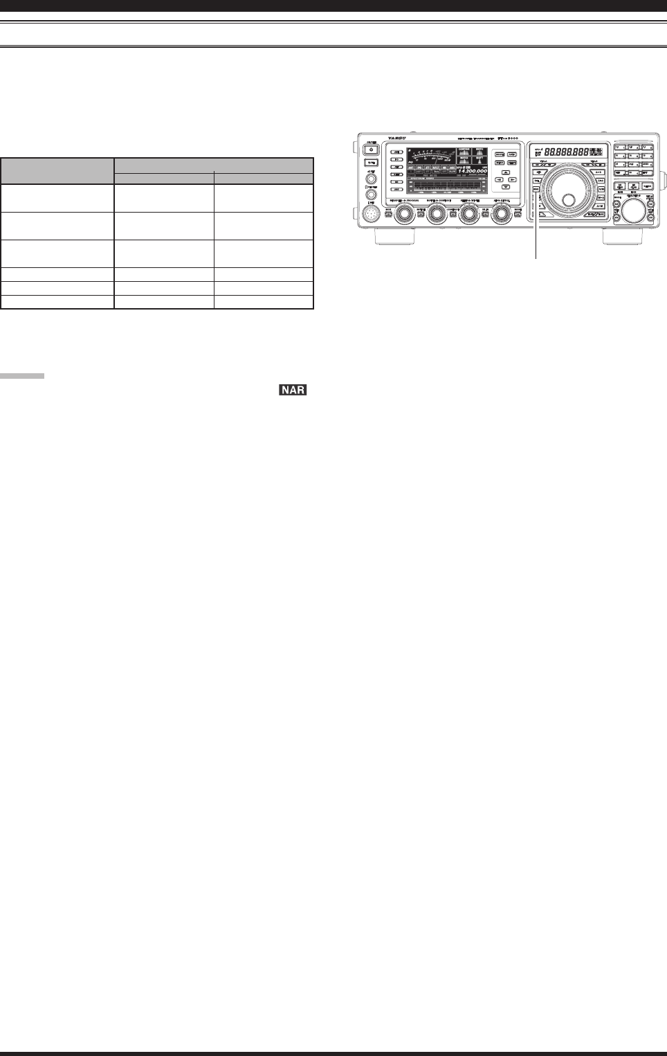
NARRow (NAR) oNe-toucH iF FilteR selectioN
Pressing the [NAR] button provides one-touch, mode-specic, selection of a narrow IF DSP lter setting that does not
require resetting the [WIDTH] knob.
Pressing the [NAR] button once more returns the band-
width control to the WITDH/SHIFT system. The factory
default bandwidths are:
: Depends on the [WIDTH] knob
( ): Default Bandwidth
opeRAtiNg Mode
SSB
CW
RTTY/PKT-L/PKT-U
PKT-FM
AM
FM (28/50 MHz Bands)
“oN”
200 Hz ~ 1.8 kHz
(1.5 kHz)
100 ~ 500 Hz
(500 Hz)
100 ~ 500 Hz
(300 Hz)
9 kHz
6 kHz
9 kHz
“oFF”
1.8 ~ 4.0 kHz
(2.4 kHz)
500 Hz ~ 2.4 kHz
(2.4 kHz)
500 Hz ~ 2.4 kHz
(500 Hz)
16 kHz
9 kHz
16 kHz
[NAR] switcH
Advice:
When the narrow bandwidth is selected, the “ ”
icon will appear in the display.
Even if the [NAR] button has been pressed to en-
gage the narrow lter, you may adjust the narrow IF
bandwidth by rotating the [WIDTH] knob. The IF
SHIFT still is operational. For many applications,
you may nd that simply pressing the [NAR] button
instead of adjustment of the [WIDTH] knob, may be
satisfactory for interference reduction.
When you press the [NAR] button in the FM mode,
both transmit and receive bandwidths are narrowed.
[NAR] Button
FCC ID: K6620461X50 / IC: 511B-20461X50
Page 53FT DX
3000 OperaTing Manual
inTerFerence rejecTiOn
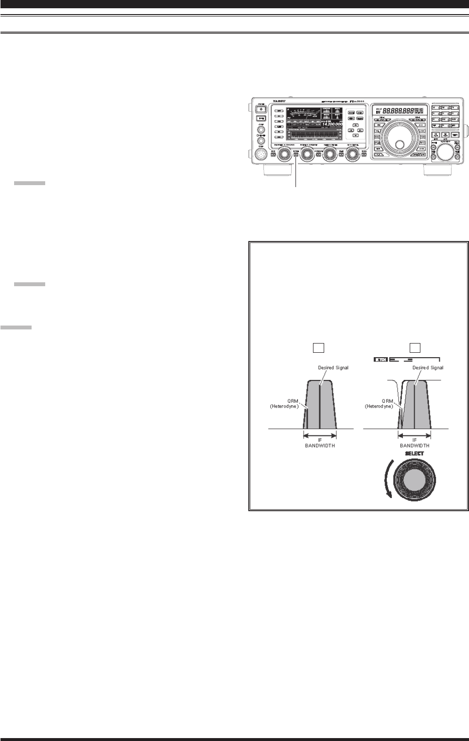
iF NotcH FilteR opeRAtioN (ssb/cw/Rtty/pKt/AM Modes)
The IF NOTCH lter is a highly effective system that allows you to slice out an interfering beat note or other carrier
signal from inside the receiver passband.
1. Press the [NOTCH] button to activate the Notch l-
ter. The LED inside the [NOTCH] button glows or-
ange and the current “null” position of the NOTCH
filter will appear in the NOTCH indicator on the
display. The [NOTCH] knob functions as the Notch
adjustment knob.
2. Rotate the [NOTCH] knob to adjust the “null” posi-
tion of the Notch lter.
Advice:
The frequency display will show the Notch frequen-
cy for 3 seconds whenever the [NOTCH] knob is
turned.
3. To cancel the NOTCH filter, press the [NOTCH]
button momentarily. The graphic disappears from the
NOTCH indicator on the display, conrming that the
NOTCH lter is no longer operation.
Advice:
Alternate presses of the [NOTCH] button, will
switch the NOTCH lter between on or off.
Advice:
The IF NOTCH Filter selection will be memorized
independently on each VFO stack of VFO-A and
VFO-B.
When the optional DMU-2000 Data Management
Unit is connected, the effect of the IF NOTCH lter
may be observed on the Audio Scope (on the “Os-
cilloscope” page). The Notch will be observed as a
“dip” in the noise platform observed. What’s more,
the “Waterfall” display may be used to observe the
effect of the IF NOTCH lter, which will appear as a
white area in the colored background area.
[NOTCH] Button
The performance of the IF NOTCH filter is
shown in Figure “A”, where the effect of rotation
of the [NOTCH] knob is depicted. In Figure “B”
you can see the notching effect of the IF NOTCH
lter as you rotate the [NOTCH] knob to elimi-
nate the incoming interference.
A B
FCC ID: K6620461X50 / IC: 511B-20461X50