Yaesu Musen 20461X50 Scanning Receiver User Manual FTDX3000 Operating Manual
Yaesu Musen Co., Ltd. Scanning Receiver FTDX3000 Operating Manual
Contents
Users Manual 6
Page 45FT DX
3000 OperaTing Manual
inTerFerence rejecTiOn
µ-tuNe FilteR (ReQuiRes tHe optioNAl RF µtuNiNg Kit)
Advice:
The µ-Tune lters are the most advanced, selective RF preselector lters ever incorporated into an Amateur Radio
transceiver. The RF selectivity provided by µ-Tune can be of tremendous value in ensuring quiet, intermod-free
reception even in the most crowded bands on a contest weekend. The µ-Tune lters provide RF selectivity on the
order of a few dozen kHz at -6 dB, at the expense of a few dB of system gain on bands where noise gure is seldom
an issue. You will notice that the S-meter deection, when µ-Tune is engaged, is slightly less than when it is out of
the circuit; this is normal. If your antenna system gain is so low that you cannot hear the band noise when µ-Tune is
engaged (highly unlikely), just switch it out, to eliminate the slight insertion loss.
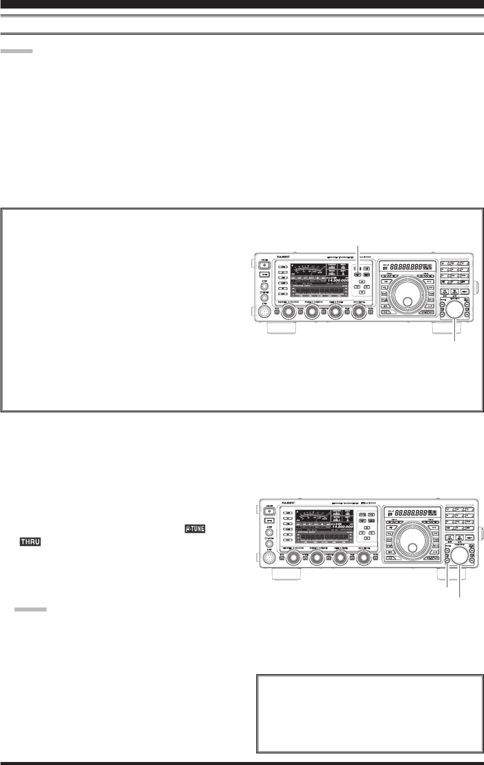
As you tune around on an amateur band with µ-Tune engaged, the microprocessor automatically commands the
stepper motor driving the toroid core stack to center the lter on your current operating frequency. You may, how-
ever, use the [SELECT(µ-TUNE)] knob to skew the lter response to one side or the other from your operating fre-
quency, to deal with heavy interference on one side. To re-center the µ-Tune lter on your operating frequency, and
eliminate any offset, press the [CLEAR] button.
ChangingtheTuningOffsetIndicator
1. Press and hold in the [MENU] button for one
second to engage the Menu mode.
2. Rotate the [CLAR/VFO-B] knob or p/q button
to select Menu item “011 DISPLAY BAR DIS-
PLAY SELECT”.
3. Rotate the [CLAR/VFO-B] knob or p/q but-
ton to select “uTUNE (µ-Tune)” (replacing the
default “CW TUNE (CW TUNING)” selection).
4. Press the [SELECT] button, then press the
[MENU] button to lock in the new setting and
exit to normal operation.
[MENU] Button
1. Connect the external equipment between the µ TO
and µ FROM jacks on the rear panel.
2. Press the [MHz/µT] button, then press the [CLAR/
VFO-B] knob. The receive signal will pass through
the external equipment. In this case, the “ ” and
“ ” icons will be shown in the FLT column of
the VFD display Block Diagram.
3. Press the [MHz/µT] button again, the receive signal
will bypass the external equipment and be applied
directly to the transceiver front-end circuit.
Advice:
Alternate presses of the [MHz/µT] button, will
switch the receive signal between the external equip-
ment or the direct front-end receive circuit.
[MHz/µT] Button
[SELECT] Knob
Advice
If you want to use an external bandpass lter or preamplier, you may connect it between the µ TO and µ FROM jacks
on the rear panel.
Important notIce!
When [µ-TUNE] is enabled, the FT DX 3000
cannot receive a signal without an external device
of jumper cable between the µ TO and µ FROM
jacks.
[CLAR/VFO-B] Knob
FCC ID: K6620461X50 / IC: 511B-20461X50
Page 46 FT DX
3000 OperaTing Manual
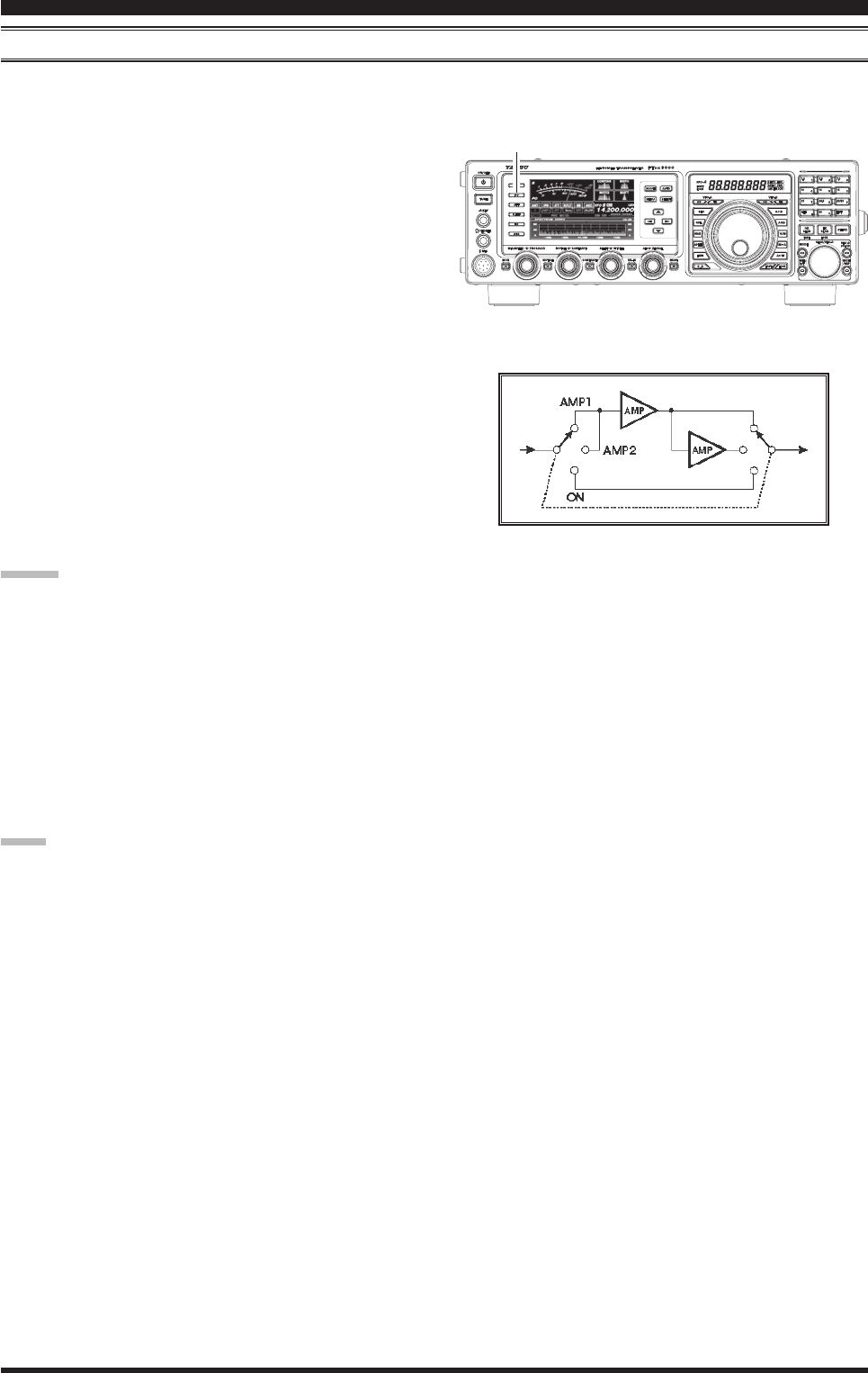
ipo (iNteRcept poiNt optiMizAtioN)
The IPO feature allows the operator to optimize the characteristics of the receiver front end, depending on the current
noise level and the strength of incoming signals.
Press the [IPO] button several times to set the desired
characteristic of the receiver front end, according to the
chart below.
AMP1: Amplies the incoming signals, using a low
distortion RF preamplier (gain: approx. 10
dB).
AMP2: Amplifies the incoming signals, using a
2-stage low-distortion RF preamplier (total
gain: approx. 17 dB).
IPO: Bypasses the RF preamplier, yielding direct
feed to the rst mixer.
The selected receiver RF preamplier will be indicated
in the IPO column of the Block Diagram Display on the
display.
Advice:
The IPO selection will be memorized independently
on each VFO stack of VFO-A and VFO-B.
On the 10 MHz and lower bands, it generally is not
necessary to use any preamplier at all; selecting the
“IPO ON” position as described above will increase
the strong-signal-handling capability of the receiver,
and generally will result in more pleasant reception
due to reduced noise. If you can hear band noise with
the preampliers disengaged, then a preamplier is
generally not needed.
Note:
The IPO feature is always on “IPO ON” (No RF pream-
plier) between 30 kHz and 1.7 MHz.
inTerFerence rejecTiOn
[IPO] Button
FCC ID: K6620461X50 / IC: 511B-20461X50
Page 47FT DX
3000 OperaTing Manual
inTerFerence rejecTiOn
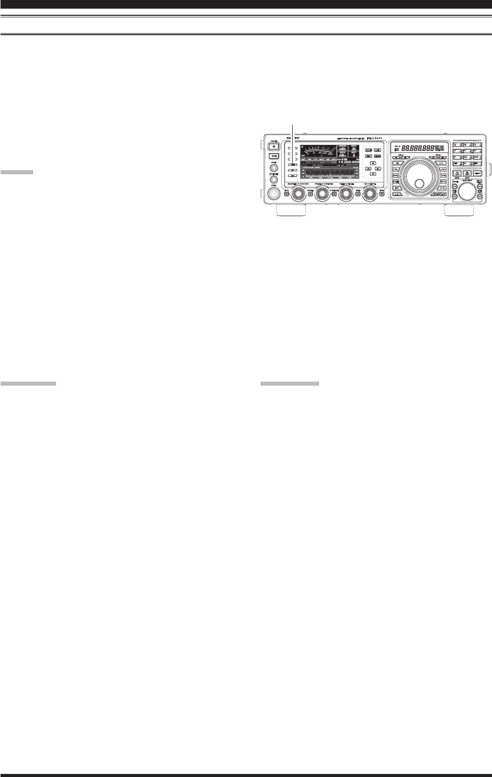
R.Flt (RooFiNg FilteRs)
Narrow-band Roong Filters of 15 kHz, 6 kHz, and 3 kHz bandwidths are provided in the rst IF, right after the rst
mixer. These lters provide protection for the 2nd mixer, DSP, and other circuitry that follow and can dramatically im-
prove reception on a very crowded band (during a contest, etc.). Typically, the AUTO selection mode is satisfactory for
most operating situations, but in an extremely crowded phone band you may wish to select, for example, the 3 kHz roof-
ing lter for SSB operation.
Press the [R.FLT] button to toggle the Roofing Filter
selection.
AUTO 15 kHz 6 kHz 3 kHz AUTO .....
Advice:
As you repeatedly press the [R.FLT] button, you will
observe changes in the notation in the R.FLT column
of the Block Diagram Display on the display, denot-
ing the Roong Filter currently in use.
Typically, this selection will be set to “AUTO.”
The Roong Filter selection will be memorized inde-
pendently on each VFO stack of VFO-A and VFO-B.
QuicK poiNt:
The “AUTO” selection of the Roong Filter is based on
the operating mode. However, you may override the au-
tomatic selection, if band conditions warrant a different
(usually, a tighter) selection.
[R.FLT] Button
teRMiNology:
A “Roong Filter,” as its name implies, places a “Roof”
over the receiver’s IF system bandwidth. This “Roof”
protects the circuitry downstream from the first mixer
from interference, just as a roof on a house protects the
contents from rain and snow.
FCC ID: K6620461X50 / IC: 511B-20461X50
Page 48 FT DX
3000 OperaTing Manual
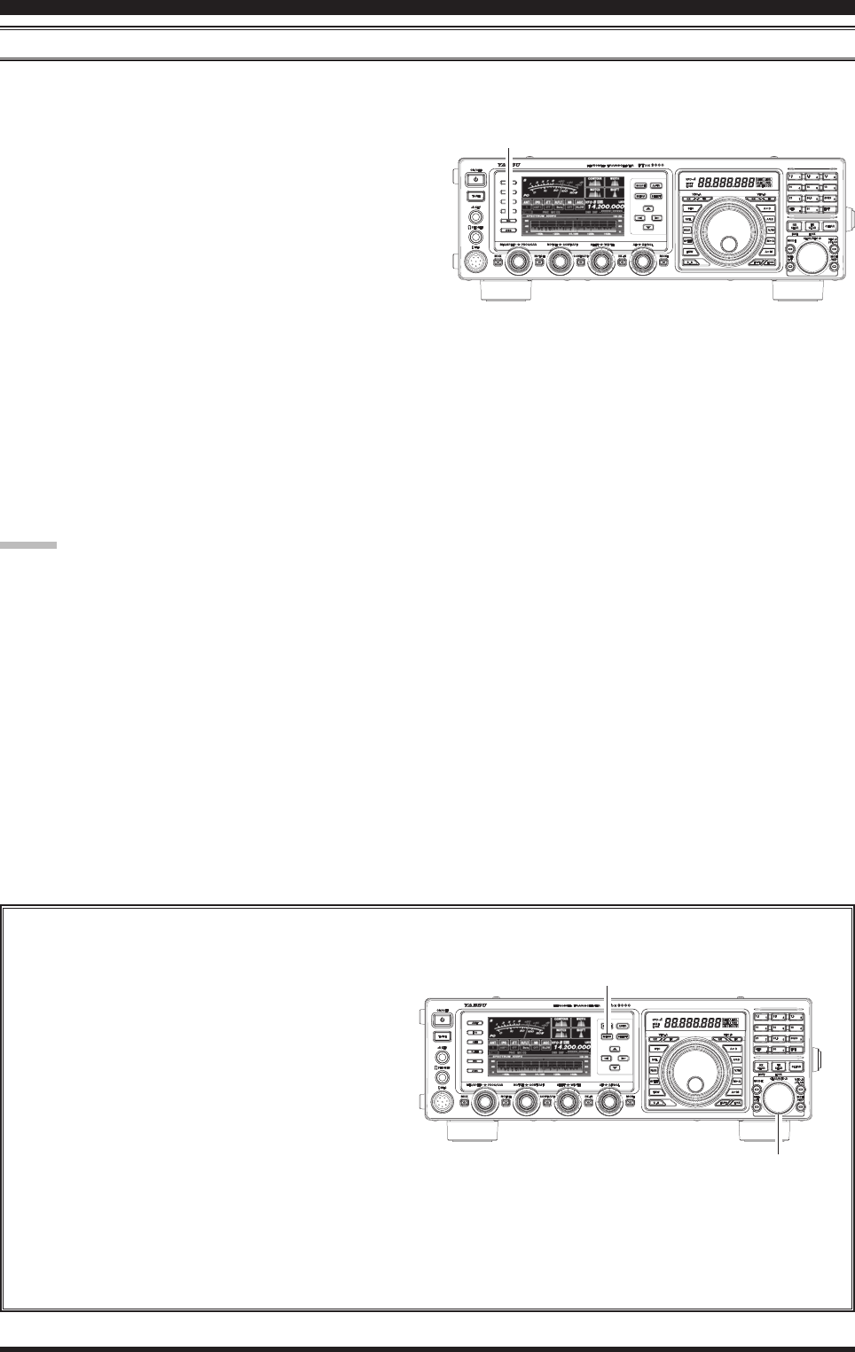
iF Noise blANKeR (Nb) opeRAtioN
The FT DX 3000 includes an effective IF Noise Blanker, which can signicantly reduce noise caused by automotive ig-
nition systems.
1. Press the [NB] button briey to reduce short dura-
tion pulse noise such as from switching transients,
automobile ignitions and power lines. The “NB ON”
will appear in the display to conrm that the Narrow-
NB is operating.
2. Press the [NB] button again to reduce longer-dura-
tion man-made pulse noise. The “NBW ON” will
appear in the display to conrm that the Wide-NB is
operating.
2. If desired, you may adjust the Noise Blanker level
via Menu item “033 GENERAL NB LEVEL” to the
point where the offending noise is best reduced or
eliminated. See box below for details.
3. To end Noise Blanker operation, press the [NB] but-
ton once more. The “NB OFF” will appear in the
display, conrming that the Noise Blanker is no lon-
ger in operation.
Advice:
The Noise Blanker operation will be memorized inde-
pendently on each VFO stack of VFO-A and VFO-B.
However, the Noise Blanker level is in common.
AdjustingtheNoiseBlankerLevel
1. Press and hold in the [MENU] button for one
second to engage the Menu mode.
2. Rotate the [CLAR/VFO-B] knob or p/q button
to select Menu item “033 GENERAL NB LEVEL”.
3. Rotate the [CLAR/VFO-B] knob or p/q but-
ton to the point where the offending noise is best
reduced or eliminated.
4. Press the [SELECT] button, then press the
[MENU] button to lock in the new setting and
exit to normal operation.
inTerFerence rejecTiOn
[NB] Button
[MENU] Button
[CLAR/VFO-B] Knob
FCC ID: K6620461X50 / IC: 511B-20461X50