Yaesu Musen 20461X50 Scanning Receiver User Manual FTDX3000 Operating Manual
Yaesu Musen Co., Ltd. Scanning Receiver FTDX3000 Operating Manual
Contents
Users Manual 1
HF/50 MHz Transceiver
FT DX 3000
OperaTing Manual
YAESU MUSEN CO., LTD.
Tennozu Parkside Building
2-5-8 Higashi-Shinagawa, Shinagawa-ku, Tokyo 140-0002 Japan
YAESU USA
6125 Phyllis Drive, Cypress, CA 90630, U.S.A.
YAESU UK LTD.
Unit 12, Sun Valley Business Park, Winnall Close
Winchester, Hampshire, SO23 0LB, U.K.
YAESU HK LTD.
Unit 1306-1308, 13F., Millennium City 2, 378 Kwun Tong Road,
Kwun Tong, Kowloon, Hong Kong
FCC ID: K6620461X50 / IC: 511B-20461X50

About this MAnuAl . . .
The FTDX3000 is a leading-edge transceiver with a number of new and exciting features, some of which may be unfa-
miliar to you. In order to gain the most enjoyment and operating efciency from your FTDX3000, we recommend that
you read this manual in its entirety, and keep it handy for reference as you explore the many capabilities of your new
transceiver.
Before using your FTDX3000, be sure to read and follow the instructions in the “Before You Begin” section of this man-
ual.
FCC ID: K6620461X50 / IC: 511B-20461X50

Page 1FT DX 3000 OperaTing Manual
general DescripTiOn
Congratulations on the purchase of your Yaesu amateur
transceiver! Whether this is your first rig, or if Yaesu
equipment is already the backbone of your station, rest
assured your transceiver will provide many hours of op-
erating pleasure for years to come.
The FT DX 3000 is an elite-class HF transceiver pro-
viding exceptional performance both on transmit and
receive. The FT DX 3000 is designed for the most
competitive operating situations, whether you primarily
operate in contest, DX, or digital-mode environments.
Built on the foundation of the popular FT DX 3000 trans-
ceiver, and carrying the proud tradition of the FT-1000
series, the FT DX 3000 provides up to 100 Watts of pow-
er output on SSB, CW, and FM (25 Watts AM carrier).
Digital Signal Processing (DSP) is utilized throughout
the design, providing leading-edge performance, both
transmit and receive.
For exceptional protection from strong signal interfer-
ence, the optional RF µTuning Kits may be connected
via the rear panel. The µTuning Kits provide extraordi-
narily sharp selectivity, and protect your receiver from
close-in interference on a crowded band.
In the front end, you may select one of two RF pream-
pliers, or IPO (Intercept Point Optimization) providing
direct feed to the rst mixer. Three levels of RF attenua-
tion are available in 6-dB steps.
The FT DX 3000 receiver utilizes DSP ltering, incor-
porating many of the features of the FT DX 9000, such
as, Variable Bandwidth, IF Shift, and Passband Contour
tuning. Also provided are Digital Noise Reduction, Digi-
tal Auto-Notch Filtering and a manually tuned IF Notch
lter.
On the transmit side, the Yaesu-exclusive Three-Band
Parametric Microphone Equalizer allows precise and
flexible adjustment of the waveform created by your
voice and microphone. The Amplitude, Center Fre-
quency, and Bandwidth are adjusted separately for the
low, mid-range, and high-frequency audio spectra. The
transmitted bandwidth may also be adjusted.
Advanced features include: Direct Keyboard Frequency
Entry and Band Change, Speech Processor, IF Monitor
for Voice modes, CW Pitch control, CW Spot switch,
Full CW QSK, adjustable IF Noise Blanker, and all-
mode Squelch. Three TX/RX antenna ports are provided
on the rear panel. Two key jacks are provided (one on
the front and one on the rear panel). The key jacks may
be congured independently for paddle input, connec-
tion to a straight key, or computer-driven keying inter-
face. The CW Message Memory is provided.
Frequency setup is straightforward on the FT DX 3000.
Enter frequency directly for both VFO-A and VFO-B.
Separate keys are provided for band selection. Each
band key provides three separate VFO settings for three
different parts of each band. You can establish three in-
dependent VFO settings of frequency, mode, and lter
for each band.
In addition, 99 memories are provided to store: Frequen-
cy, Mode, IF lter selection, Clarier offset, and Scan-
skip status. What’s more, five quick-recall (“QMB”)
memories can instantly store operational settings at the
push of a button.
The built-in antenna tuner includes 100 memories that
automatically store antenna matching settings for rapid
automatic recall later.
Interfacing for digital modes is extremely simple with
the FT DX 3000, thanks to the dedicated RTTY/PKT
connection jack on the rear panel. Optimization of the
lter passband, DSP settings, carrier insertion point, and
display offset for digital modes, is possible via the Menu
programming system.
Advanced technology is only part of the FT DX 3000
story. Yaesu stands behind our products with a world-
wide network of dealers and service centers. We greatly
appreciate your investment in the FT DX 3000, and we
look forward to helping you get the most out of your
new transceiver. Please feel free to contact your nearest
dealer, or one of Yaesu’s national headquarters ofces,
for technical advice, interfacing assistance, or accessory
recommendation. Watch Yaesu U.S.A.’s Home Page for
late-breaking information about Standard Horizon and
Yaesu products: http://www.yaesu.com.
Please read this manual thoroughly, to gain maximum
understanding of the full capability of the FT DX 3000.
We thank you again for your purchase!
FCC ID: K6620461X50 / IC: 511B-20461X50

Page 2 FT DX 30
00 OperaTing Manual
Table OF cOnTenTs
General Description ..................................................... 1
Accessories & Options ................................................. 4
Supplied Accessories ................................................ 4
Available Options ..................................................... 5
Before You Begin .......................................................... 6
Extending the Front Feet .......................................... 6
Adjusting the Main Tuning Dial Torque .................. 6
Resetting the Microprocessor ................................... 7
Resetting Memories (Only) ................................ 7
Menu Resetting ................................................... 7
Full Reset ............................................................ 7
Installation and Interconnections ............................... 8
Antenna Considerations ........................................... 8
About Coaxial Cable ................................................ 8
Grounding ................................................................. 9
Connection of Antenna and Power Cables ............. 10
Connection of Microphone and Headphone ........... 11
Key, Keyer, and Computer-Driven Keying
Interconnections ..................................................... 12
VL-1000 Linear Amplier Interconnections .......... 13
Interfacing to Other Linear Ampliers ................... 14
Plug/Connector Pinout Diagrams ............................. 15
Front Panel Controls & Switches ............................. 16
Display Indications..................................................... 26
Rear Panel ................................................................... 29
Basic Operation: Receiving on Amateur Bands ...... 31
Operation on 60-Meter (5 MHz) Band
(U.S and U.K. version only) ................................... 34
CLAR (Clarier) Operation ................................... 35
LOCK ..................................................................... 36
DIMMER ............................................................... 36
Convenience Features ................................................ 37
Using VFO-B ......................................................... 37
Band Stack Operation ............................................. 39
C.S (Custom Switch) .............................................. 39
Rotator Control Functions ...................................... 40
More Frequency Navigation Techniques ............... 41
Keyboard Frequency Entry .................................... 41
Using the [CLAR/VFO-B] knob ...................... 41
Using the UP/DOWN switches of
the supplied MH-31B8 Hand Microphone ........ 41
Interference Rejection ............................................... 42
Receiver Operation (Front End Block Diagram) ... 42
ATT ......................................................................... 43
µ-Tune Filter .......................................................... 44
IPO (Intercept Point Optimization) ........................ 46
R.FLT (Roong Filters) .......................................... 47
IF Noise Blanker (NB) Operation .......................... 48
CONTOUR Control Operation .............................. 49
IF SHIFT Operation ............................................... 50
WIDTH (IF DSP Bandwidth) Tuning .................... 51
Using IF Shift and Width Together ................... 51
NARROW (NAR) One-Touch IF Filter Selection 52
IF Notch Filter Operation ....................................... 53
Digital Notch Filter (DNF) Operation .................... 54
Digital Noise Reduction (DNR) Operation ............ 54
RF Gain (SSB/CW/AM Modes) ............................ 55
Tools for Comfortable and Effective Reception ...... 56
Audio Pitch Control ............................................... 56
Mute Feature .......................................................... 56
AGC (Automatic Gain Control) ............................. 57
SSB/AM Mode Transmission .................................... 58
Using the Automatic Antenna Tuner ........................ 60
ATU Operation ....................................................... 60
About ATU Operation ............................................ 61
Enhancing Transmit Signal Quality ......................... 62
Parametric Microphone Equalizer .......................... 62
Using the Speech Processor ................................... 64
Adjusting the SSB Transmitted Bandwidth ........... 65
Transmitter Convenience Features .......................... 66
Voice Memory ........................................................ 66
Voice Memory Operation from
the optional FH-2 Remote Control Keypad ...... 66
VOX (Automatic TX/RX Switching using Voice Control) ........... 68
MONITOR ............................................................. 69
Split Operation Using the TX Clarier .................. 70
Split-Frequency Operation ..................................... 71
Quick Split Operation ....................................... 71
FCC ID: K6620461X50 / IC: 511B-20461X50

Page 3FT DX 30
00 OperaTing Manual
Table OF cOnTenTs
CW Mode Operation ................................................. 72
Setup for Straight Key
(and Straight Key emulation) Operation ................ 72
Using the Built-in Electronic Keyer ....................... 73
Full Break-in (QSK) Operation ........................ 74
Setting the Keyer Weight (Dot/Dash) Ratio ...... 74
Selecting the Keyer Operating Mode ............... 75
CW Convenience Features ........................................ 78
Audio Peak Filter ................................................... 76
CW Spotting (Zero-Beating) .................................. 77
Using CW Reverse ................................................. 78
CW Delay Time Setting ......................................... 79
CW Pitch Adjustment ............................................. 79
Contest Memory Keyer
(Using the optional FH-2 Remote Control Keypad)
..... 80
Message Memory ............................................. 80
TEXT Memory ................................................. 82
FM Mode Operation .................................................. 85
Basic Operation ...................................................... 85
Repeater Operation ................................................. 86
Tone Squelch Operation ......................................... 87
Memory Operation .................................................... 88
Convenient Memory functions ............................... 88
QMB (Quick Memory Bank) ................................. 89
Standard Memory Operation .................................. 90
Memory Storage ............................................... 90
Memory Channel Recall ................................... 90
Checking Memory Channel Status ................... 91
Erasing Memory Channel Data ........................ 91
Moving Memory Data to
the Main Band (VFO-A)................................... 92
Memory Tune Operation .................................. 92
Memory Groups ................................................ 93
Memory Group Assignment ............................. 93
Choosing the Desired Memory Group .............. 93
Operation on Alaska Emergency Frequency:
5167.5 kHz (U.S. Version Only) ................................ 94
VFO and Memory Scanning ..................................... 95
VFO Scanning ........................................................ 95
Memory Scan ......................................................... 96
PMS (Programmable Memory Scan) ....................... 97
Packet Operation ....................................................... 98
Packet Setup (Including Subcarrier Frequency) ..... 98
Basic Setup ............................................................. 98
RTTY (Radio Teletype) Operation ........................... 99
Setting Up for RTTY Operation ............................. 99
Basic Setup ............................................................. 99
Miscellaneous AFSK-Based Data Modes ............... 100
Menu Mode ............................................................... 102
Using the Menu .......................................................... 102
Menu Mode Reset ...................................................... 102
Specications ............................................................ 108
FCC Notice ............................................................... 110
FCC ID: K6620461X50 / IC: 511B-20461X50

Page 4 FT DX 30
00 OperaTing Manual
accessOries & OpTiOns
Supplied AcceSSorieS
Hand Microphone (MH-31B8) 1 pc A07890001
FH-2 Remote Control Keypad
DC Power Cord 1 pc T9025225
Spare Fuse (25A) 1 pc Q0000074
Operating Manual 1 pc
Warranty Card 1 pc
FCC ID: K6620461X50 / IC: 511B-20461X50
Page 5FT DX 30
00 OperaTing Manual
accessOries & OpTiOns
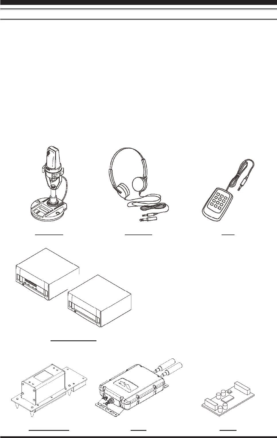
AvAilAble optionS
MD-200A8X Ultra-High-Fidelity Desktop Microphone
MD-100A8X Desktop Microphone
YH-77STA Lightweight Stereo Headphone
VL-1000/VP-1000 Linear Amplier/AC Power Supply
RF µTuning Kit A For 160 m Band
RF µTuning Kit B For 80/40 m Bands
RF µTuning Kit C For 30/20 m Bands
FC-40 External Automatic Antenna Tuner
DVS-6 Voice Memory Unit
FH-2 Remote Control Keypad
CT-118 VL-1000 Linear Amplire Connection Cable
CT Cable (MDIN6P - MDIN6P 2m) Antenna Rotator Connection Cable (P/N T9101556)
CT Cable (MDIN10P - Bare Wire 2m) Linear Amplier Connection Cable (P/N T9207451)
MD-200A8X YH-77STA FH-2
VL-1000/VP-1000
RF µTuning Kit DVS-6FC-40
FCC ID: K6620461X50 / IC: 511B-20461X50
Page 6 FT DX 30
00 OperaTing Manual
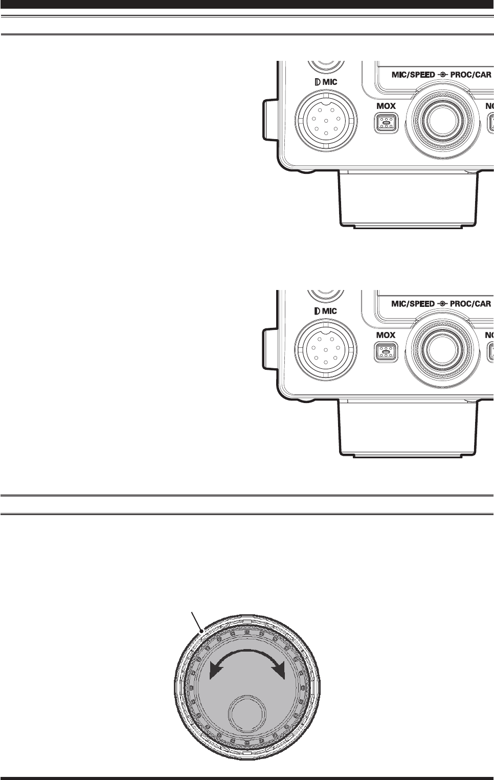
extending the Front Feet
To elevate the front panel for easy viewing, the front left and right feet of the bottom case may be extended.
Pull the front legs outward from the bottom panel.
Rotate the legs counter-clockwise to lock them in
the extended position. Be sure the legs have locked
securely in place, because the transceiver is quite
heavy and an unlocked leg could result in damage,
should the transceiver move suddenly.
Retracting the Front Feet
Rotate the legs clockwise, and push them inward
while rotating to the right.
The front feet should now be locked in the retracted
position.
AdjuSting the MAin tuning diAl torque
The torque (drag) of the Main Tuning Dial knob may
be adjusted according to your preferences. Simply hold
down the rear skirt of the knob, and while holding it in
place rotate the knob clockwise to reduce the drag or
counter-clockwise to increase the drag.
beFOre YOu begin
Hold the Skirt
TIGHTEN LOOSEN
FCC ID: K6620461X50 / IC: 511B-20461X50
Page 7FT DX 30
00 OperaTing Manual
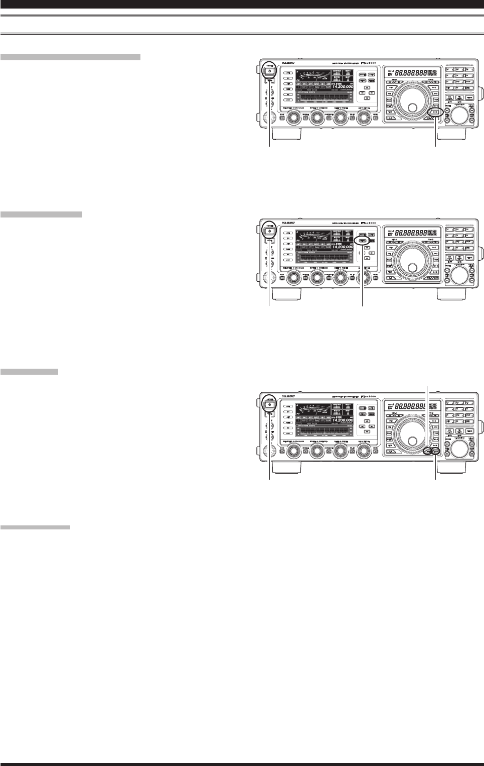
[POWER] button [A
M] button
beFOre YOu begin
reSetting the MicroproceSSor
reSetting MeMorieS (only)Use this procedure to reset (clear) the previously stored
Memory channels, without affecting any conguration
changes you may have made to the Menu settings.
1. Press the front panel’s [POWER] switch to turn the
transceiver off.
2. Press and hold in the [A
M] button; while holding
it in, press and hold in the front panel’s [POWER]
switch to turn the transceiver on. Once the transceiv-
er comes on, you may release the buttons.
Menu reSetting
Use this procedure to restore the Menu settings to their
factory defaults, without affecting the memories you
have programmed.
1. Press the front panel [POWER] switch to turn the
transceiver off.
2. Press and hold in the [MENU] button; while holding
it in, press and hold in the front panel [POWER]
switch to turn the transceiver on. Once the transceiv-
er comes on, you may release the buttons.
Full reSet
Use this procedure to restore all Menu and Memory set-
tings to their original factory defaults. All Memories will
be cleared by this procedure.
1. Press the front panel [POWER] switch to turn the
transceiver off.
2. Press and hold the [FAST] and [LOCK] buttons;
while holding them in, press and hold in the front
panel [POWER] switch to turn the transceiver on.
Once the transceiver comes on, you may release the
buttons.
iMportAnt note:
When the optional µTuning Kit is connected to the
FT DX 3000, disconnect all the cables from the µTuning
Kit before performing the Full Reset.
[LOCK] button
[FAST] button
[POWER] button [MENU] button
[POWER] button
FCC ID: K6620461X50 / IC: 511B-20461X50
Page 8 FT DX 30
00 OperaTing Manual
AntennA conSiderAtionS
The FT DX 3000 is designed for use with any antenna system providing a 50 Ohm resistive impedance at the desired op-
erating frequency. While minor excursions from the 50-Ohm specication are of no consequence, if the Standing Wave
Ratio (SWR) present at the Antenna jack is greater than 3:1, the transceiver’s Automatic Antenna Tuner may not be able
to reduce the impedance mismatch to an acceptable value.
Every effort should be made to ensure that the impedance of the antenna system be as close as possible to the specied
50-Ohm value. Note that the “G5RV” type antenna does not provide a 50-Ohm impedance on all HF Amateur bands. An
external wide-range antenna coupler must be used with this antenna type.
Any antenna to be used with the FT DX 3000 must be fed from the transceiver with 50 Ohm coaxial cable. Therefore,
when using a “balanced” antenna such as a dipole, remember that a balun or other matching/balancing device must be
used to ensure proper antenna performance.
The same precautions apply to any additional (receive-only) antennas connected to the antenna jacks; if your receive-
only antennas do not have impedance near 50 Ohms at the operating frequency, you may need to install an external an-
tenna tuner to obtain optimum performance.
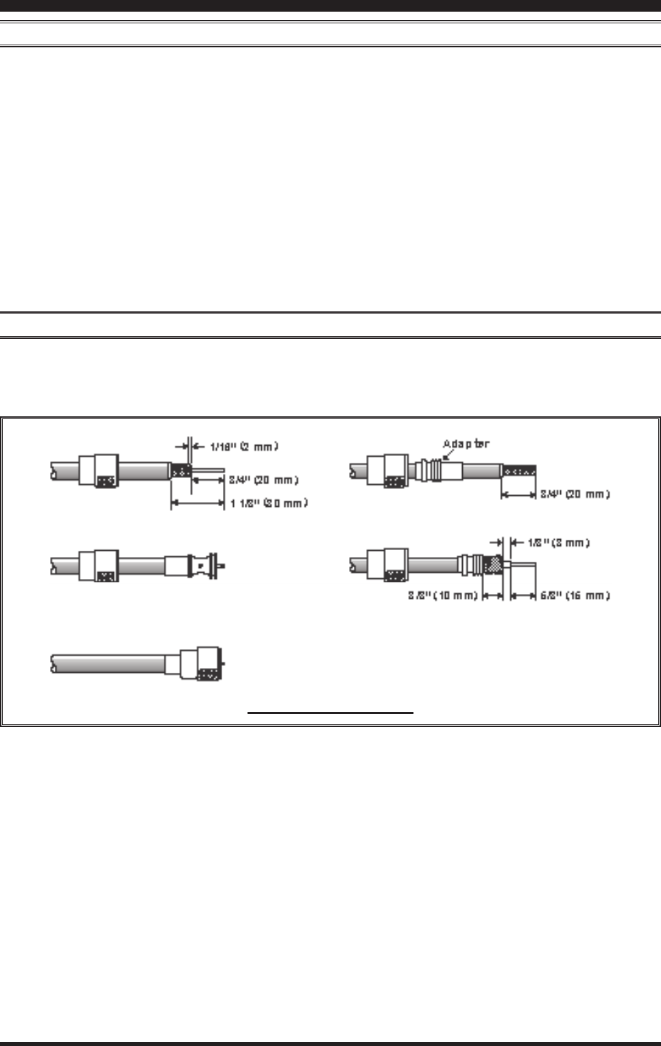
About coAxiAl cAble
Use high-quality 50-Ohm coaxial cable for the lead-in to your FT DX 3000 transceiver. All efforts at providing an ef-
cient antenna system will be wasted if poor quality, lossy coaxial cable is used. This transceiver utilizes standard “M”
(“PL-259”) type connectors.
insTallaTiOn anD inTercOnnecTiOns
typicAl pl-259 inStAllAtion
FCC ID: K6620461X50 / IC: 511B-20461X50
Page 9FT DX 30
00 OperaTing Manual
insTallaTiOn anD inTercOnnecTiOns
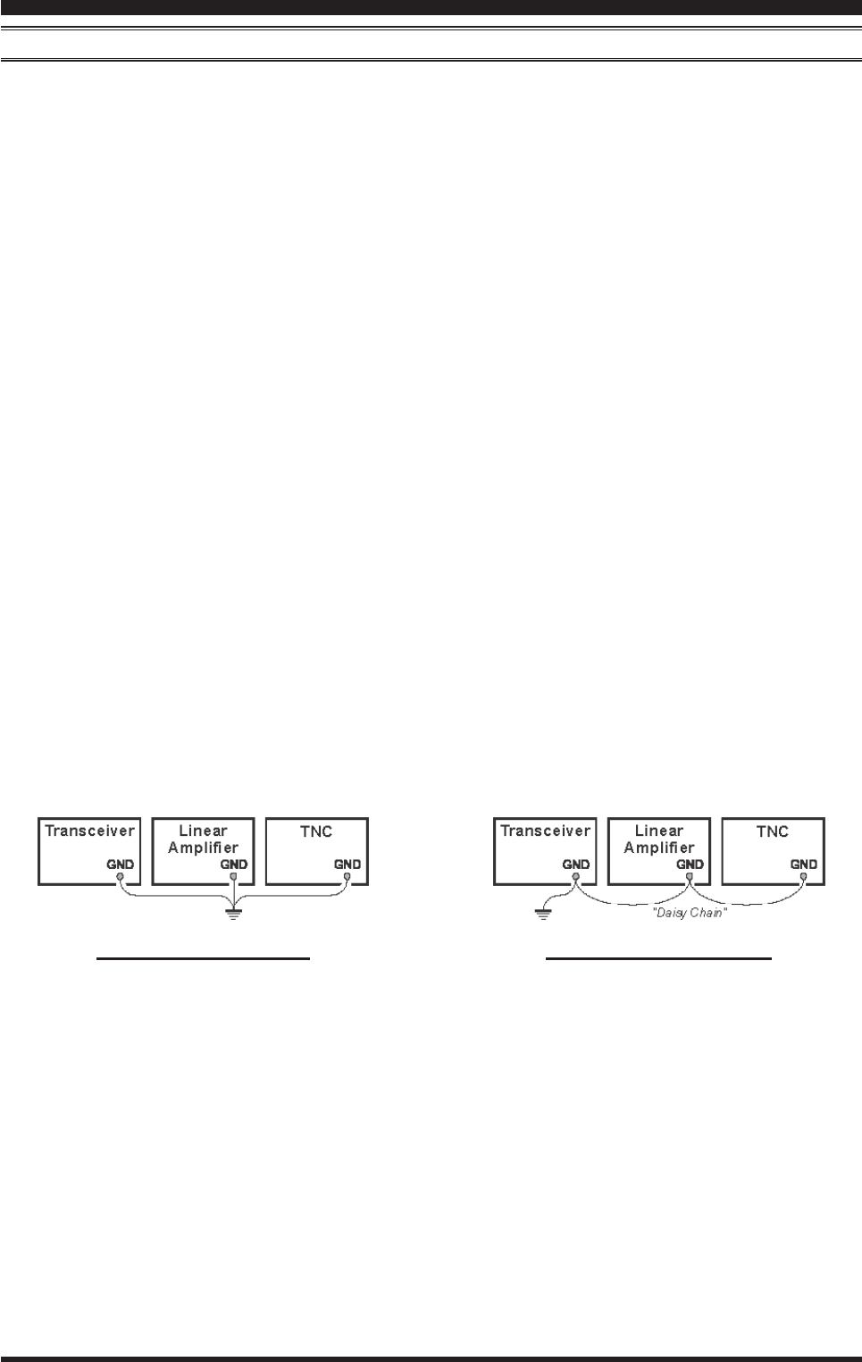
proper ground connection iMproper ground connection
grounding
The FT DX 3000 transceiver, like any other HF communications apparatus, requires an effective ground system for
maximum electrical safety and best communications effectiveness. A good ground system can contribute to station ef-
ciency in a number of ways:
It can minimize the possibility of electrical shock to the operator.
It can minimize RF currents owing on the shield of the coaxial cable and the chassis of the transceiver; such cur-
rents may lead to radiation, which can cause interference to home entertainment devices or laboratory test equip-
ment.
It can minimize the possibility of erratic transceiver/accessory operation caused by RF feedback and/or improper
current ow through logic devices.
An effective earth ground system may take several forms; for a more complete discussion, see an appropriate RF engi-
neering text. The information below is intended only as a guideline.
Typically, the ground connection consists of one or more copper-clad steel rods, driven into the ground. If multiple
ground rods are used, they should be positioned in a “V” conguration, and bonded together at the base of the “V”
which is nearest the station location. Use a heavy, braided cable (such as the discarded shield from type RG-213 coaxial
cable), and strong cable clamps to secure the braided cable(s) to the ground rods. Be sure to weatherproof the connec-
tions to ensure many years of reliable service. Use the same type of heavy, braided cable for the connections to the sta-
tion ground bus (described below).
Inside the station, a common ground bus consisting of a copper pipe of at least 25 mm diameter should be used. An al-
ternative station ground bus may consist of a wide copper plate (single-sided circuit board material is ideal) secured to
the bottom of the operating desk. Grounding connections from individual transceivers, power supplies, and data com-
munications devices (TNCs, etc.) should be made directly to the ground bus using a heavy, braided cable.
Do not “Daisy-Chain” ground connections from one electrical device to another, and thence to the ground bus. This
method may nullify any attempt at effective radio frequency grounding. See the drawing below for examples of proper
grounding techniques.
Inspect the ground system - inside the station as well as outside - on a regular basis to ensure continued performance
and safety.
Besides following the above guidelines carefully, note that household or industrial gas lines must never be used in an
attempt to establish an electrical ground. Cold water pipes may, in some instances, help in the grounding effort, but gas
lines represent a signicant explosion hazard, and must never be used.
FCC ID: K6620461X50 / IC: 511B-20461X50
Page 10 FT DX 30
00 OperaTing Manual
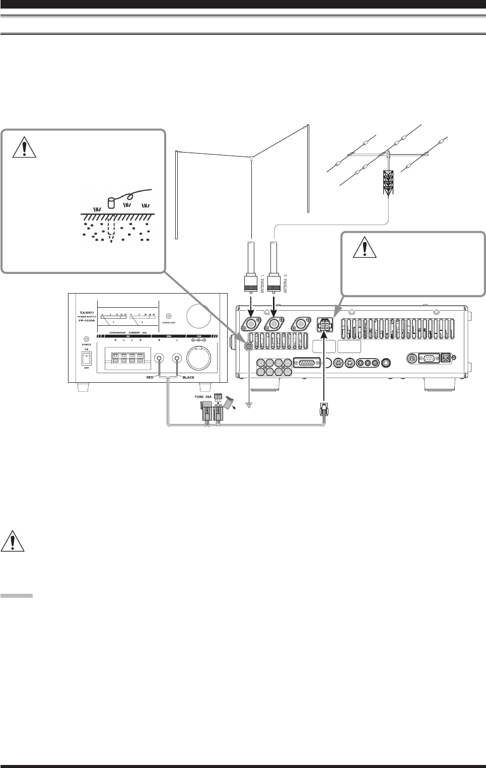
connection oF AntennA And power cAbleS
Please follow the outline in the illustration regarding the proper connection of antenna coaxial cables, as well as the DC
power cable. The DC power connector for the FT DX 3000 must only be connected to a DC source providing 13.8 Volts
DC (±10 %), and capable of at least 23 Amperes of current. Always observe proper polarity when making DC connec-
tion:
The RED DC power lead connects to the Positive (+) DC terminal.
The BLACK DC power lead connects to the Negative (–) DC terminal.
We recommend the use of the FP-1030A AC Power Supply. Other models of power supplies may be used with the FT
DX 3000, but the 13.8 VDC input voltage, 23 Ampere current capability, and DC cable polarity guidelines described
above must be strictly followed.
Note that other manufacturers may use the same type of DC power connections as does your FT DX 3000 transceiver,
however, the wiring conguration may be different from that specied for your transceiver. Serious damage can be
caused if improper DC connections are made; consult with a qualied service technician when in doubt.
Permanent damage can result when improper supply voltage, or reverse-polarity voltage, is applied to the FT DX
3000. The Limited Warranty on this transceiver does not cover damage caused by application of AC voltage, re-
verse polarity DC, or DC voltage outside the specied range of 13.8 V ±10 %. When replacing fuses, be certain to use a
fuse of the proper rating. The FT DX 3000 requires a 25 A blade fuse.
Advice:
Do not position the FT DX 3000 in a location with direct exposure to sunshine.
Do not position the FT DX 3000 in a location exposed to dust and/or high humidity.
Ensure adequate ventilation around the FT DX 3000, to prevent heat build-up and possible reduction of performance
due to high heat.
Do not install the FT DX 3000 on an unstable desk or table. Do not place in a location where objects may fall onto it
from above.
To minimize the possibility of interference to home entertainment devices, take all precautionary steps including
separation of TV/FM antennas from Amateur transmitting antennas to the greatest extent possible, and keep trans-
mitting coaxial cables separated from cables connected to home entertainment devices.
Ensure that the DC power cord is not subject to undue stress or bending, which could damage the cable or cause it to
be accidentally unplugged from the rear panel DC IN jack.
Be certain to install your transmitting antenna(s) so they cannot possibly come in contact with TV/FM radio or other
antennas, or with power or telephone lines.
insTallaTiOn anD inTercOnnecTiOns
To prevent the damage from
a thunder, atmospheric elec-
tricity, electrical shock etc., please
take a good earth ground.
U s e a s h o r t ,
thick, braided
cable to con-
nect your station
equipment to the
buried ground rod (or alternative earth
ground system).
Ch eck a DC volt ag e
a n d c u r r e n t r a t i n g
(+13.8 V, 23 A) of the power
supply before connecting to the
transceiver.
FCC ID: K6620461X50 / IC: 511B-20461X50
Page 11FT DX 30
00 OperaTing Manual
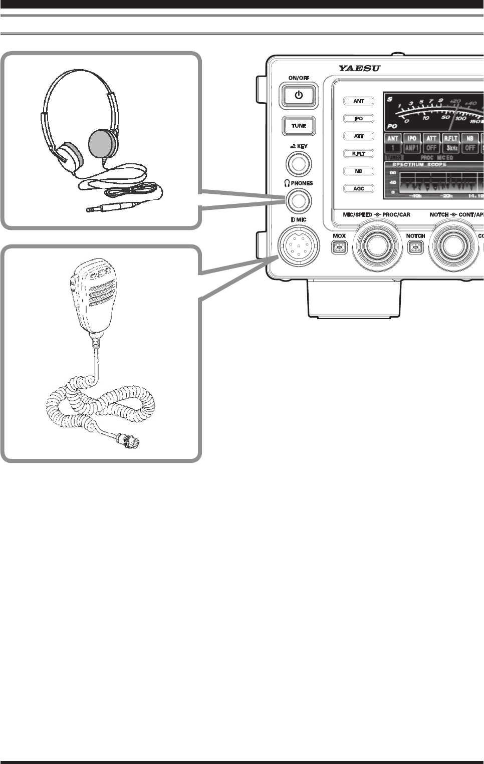
insTallaTiOn anD inTercOnnecTiOns
connection oF Microphone And heAdphone
FCC ID: K6620461X50 / IC: 511B-20461X50
Page 12 FT DX 30
00 OperaTing Manual
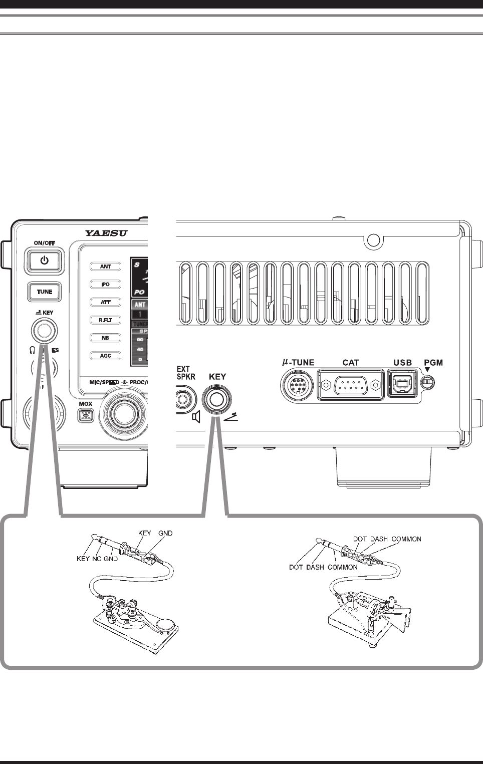
Key, Keyer, And coMputer-driven Keying interconnectionS
The FT DX 3000 includes many features for the CW operator. These functions will be detailed in the “Operation” sec-
tion later. Besides the built-in Electronic Keyer, two key jacks are provided, one on the front and one on the rear panel,
for convenient connection to keying devices.
The Menu selections allow you to congure the front and rear panel KEY jacks according to the device you wish to con-
nect. For example, you may connect your keyer paddle to the front panel KEY jack, and use Menu item “018 KEYER F
KEYER TYPE” for paddle input, and also connect the keying line from your personal computer (which emulates a “straight
key”), to the rear panel KEY jack, and congure the rear panel jack using Menu item “020 KEYER R KEYER TYPE”.
Both KEY jacks on the FT DX 3000 utilize “Positive” keying voltage. Key-up voltage is approximately +3.3V DC, and
key-down current is approximately 0.3 mA. When connecting a key or other device to the KEY jacks, use only a 3-con-
tact (“stereo”) 1/4” phone plug; a 2-contact plug will place a short between the ring and (grounded) shaft of the plug,
resulting in a constant “key-down” condition in some circumstances.
insTallaTiOn anD inTercOnnecTiOns
FCC ID: K6620461X50 / IC: 511B-20461X50
Page 13FT DX 30
00 OperaTing Manual
insTallaTiOn anD inTercOnnecTiOns
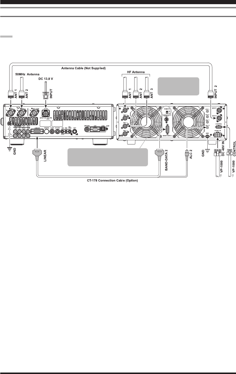
vl-1000 lineAr AMpliFier interconnectionS
Be sure that both the FT DX 3000 and VL-1000 are turned off, then follow the installation recommendations contained
in the illustration.
note:
Please refer to the VL-1000 Operating Manual for details regarding amplier operation.
Please do not attempt to connect or disconnect coaxial cables when your hands are wet.
To link the FTDX3000 and VL-1000 Power
switches, set the VL-1000 REMOTE switch
to the “ON” position.
Set the front panel’s
INPUT switch to the
“INPUT2”.
FCC ID: K6620461X50 / IC: 511B-20461X50