Yaesu Musen 20461X50 Scanning Receiver User Manual FTDX3000 Operating Manual
Yaesu Musen Co., Ltd. Scanning Receiver FTDX3000 Operating Manual
Contents
Users Manual 3
Page 29FT DX 30
00 OperaTing Manual
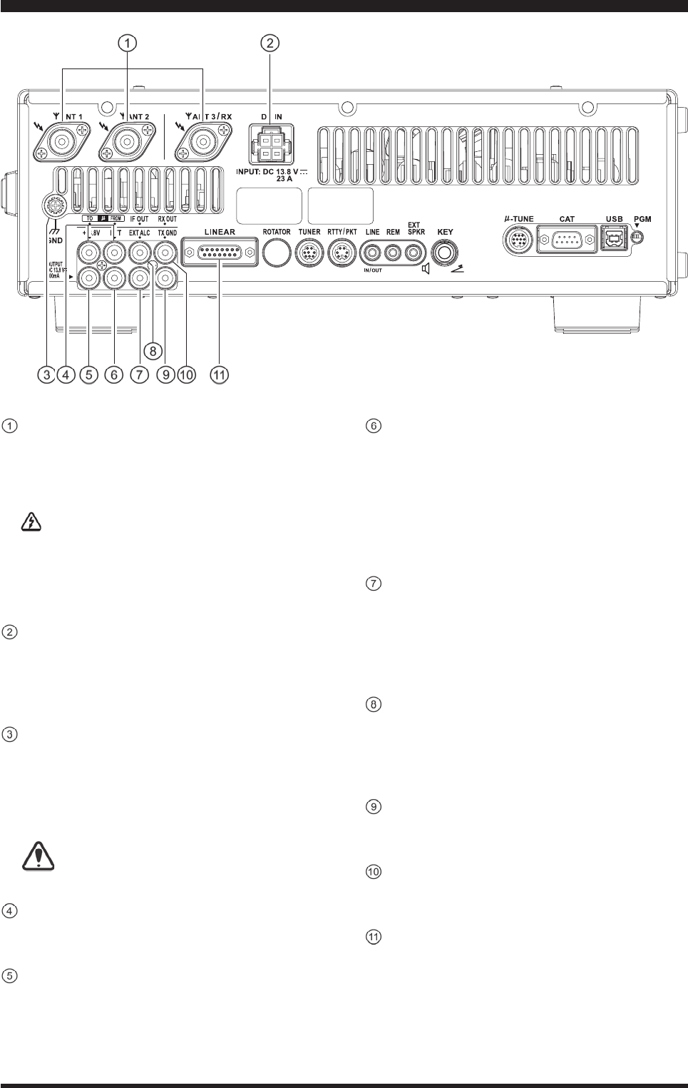
rear panel
ANT1/2/3 Jacks
Connectyourmainantenna(s)here,usingatype-M
(PL-259) connector and coaxial feed lines.The in-
ternalantennatuneraffectsonlytheantenna(s)con-
nectedhere,andonlyduringtransmission.
Warning!
The100VRFvoltage(@100W/50)isappliedto
the TX RF section of the transciver while trans-
mitting.DonottouchtheTXRFsectionabso-
lutelywhiletransmitting.
DCIN Jack
ThisistheDCpowersupplyconnectionforthe
transceiver.UsethesuppliedDCcabletoconnectdi-
rectlytoaDCpowersupply,whichmustbecapable
ofsupplyingatleast23A@13.8VDC.
GND
Usethisterminaltoconnectthetransceivertoagood
earth ground, for safety and optimum performance.
Usealargediameter,shortbraidedcableformaking
ground connections, and please refer to page 9 for
othernotesaboutpropergrounding.
Topreventthedamagefromathunder,at-
mosphericelectricity, electrical shocketc.,
pleasetakeagoodearthground.
µ-TUNE Jacks
These jacks are used to connect the optional RF
µTuningKit,signalinandsignalout.
+13.8VJack
ThisRCAoutputjackprovidesregulated,separately
fused 13.8 VDC at up to 200 mA, to power an ex-
ternaldevicesuchasapacketTNC.Makesureyour
devicedoesnotrequiremorecurrent(ifitdoes,use
aseparatepowersource).
PTT Jack
ThisRCAinputjackmaybeusedtoprovidemanual
transmitter activation using a footswitch or other
switchingdevice.Itsfunctionisidenticaltothe
[MOX] button on the front panel.The same line is
available at the RTTY/PKT jack for TNC control.
Open-circuit voltage is +5VDC, and closed-circuit
currentis1mA.
EXTALCJack
This RCA input jack accepts negative-going exter-
nalALC (Automatic Level Control)voltagefrom
a linear amplier, to prevent over-excitationby the
transceiver.Acceptableinputvoltagerangeis0to–4
VDC.
IFOUTJack
ThisRCAinputjackoutputsthe9MHzIFsignalof
thereceivedsignalwhenMenuitem“109 RGEN
IFOUT”issetto“ENABLED”.Thissignaldoesnot
passthroughtheroonglter.
TXGNDJack
ThisRCAjack’scenterpinisclosedtogroundwhile
thetransceiver’stransmitterisengaged.
RXOUTJack
ThisRCA inputjack provideoutput of thereceiver
signallinesfromtheAntennajack.
LINEAR Jack
This15-pinoutputjackprovidesbandselectiondata,
whichmaybe usedfor controlofoptional accesso-
riessuchastheVL-1000Solid-stateLinearAmpli-
er.
FCC ID: K6620461X50 / IC: 511B-20461X50
Page 30 FT DX 3000 OperaTing Manual
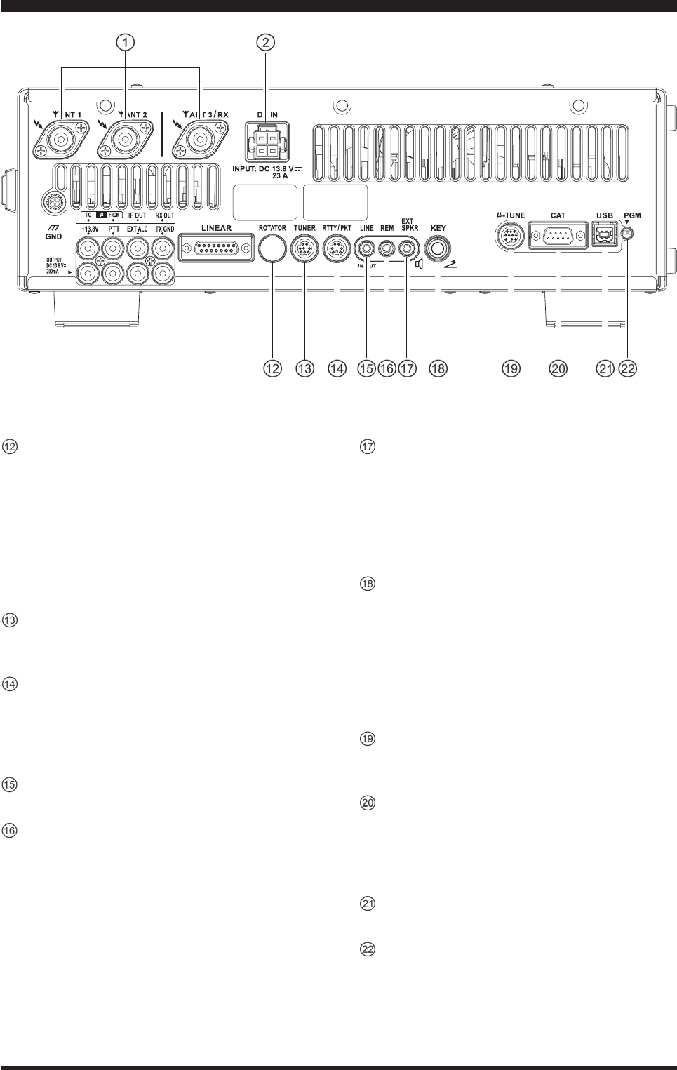
rear panel
ROTATOR Jack
This covered 6-pin MINI-DIN Jack accepts a cable
to connect to aYAESU G-800DXA/-1000DXA/
-2800DXA (for USA/EXP market) or G-800DXC/
-1000DXC/-2800DXC (for Europeanmarket)An-
tenna Rotator (listed models are current as of early
2012).Youmaycontroltheantennaazimuthrotation
(and rotation speed) using the Function buttons on
thefrontpanel.
TUNER Jack
This8-pinoutputjackisusedforconnectiontothe
FC-40ExternalAutomaticAntennaTuner.
RTTY/PKT Jack
This 6-pininput/outputjackacceptsAFSKinput
from a Terminal Node Controller (TNC); it also
providesxedlevel(100-mV@600Ohms)receiver
audiooutput,andFSKkeyingline.
LINE Jack
T.B.D.
REM (REMOTE) Jack
By plugging in the optional FH-2 Remote Control
Keypadtothisgold-platedjack,directaccesstothe
FTDX3000CPUisprovidedforcontrolfunctions
suchascontestmemorykeying,plusfrequencyand
functioncontrol.
EXTSPKR Jack
This 3.5-mm, 2-contact, gold-platedjack provides
variableaudiooutputforanexternalloudspeaker.
Theaudiooutputimpedanceatthisjackis4-8
Ohms, and the level varies according to the setting
ofthefrontpanel[AFGAIN]knob.Insertingaplug
intothisjackdisablestheinternalloudspeaker.
KEYJack
This1/4-inch 3-contactjackacceptsaCW keyor
keyerpaddle.Atwo-contactplug cannot beused in
thisjack.Key-upvoltageis+3.3VDC,andkey-
down current is 0.3 mA. This jack may be config-
ured for keyer, “Bug”, “straight key”, or computer
keyinginterfaceoperationviaMenuitem“039 A1A
R-TYPE”.
µ-TUNE Jack
Thiscovered10-pinmini-DINjackisusedforcon-
troloftheoptionalRFµTuningKit.
CAT Jack
This9-pinserialDB-9jackallowsexternalcomputer
control of the FT DX 3000. Connect a serial cable
hereandtotheRS-232CCOMportonyourpersonal
computer(noexternalinterfaceisrequired).
USB Jack
T.B.D.
PGM-SW Switch
Thisslideswitchisusedforupdatingthetransceiv-
er’srmware.The updatesoftware and instructions
areavailablefordownloadfromtheYAESUwebsite
(http://www.yaesu.com/).
FCC ID: K6620461X50 / IC: 511B-20461X50

Page 31FT DX 3000 OperaTing Manual
Before turning on main power, please verify the following items once more.
Have you made all ground connections securely? See page ?? for details.
Do you have your antenna(s) connected to the rear-panel Antenna jack(s)? See page ?? for details.
Is your microphone (and/or key or paddle) connected? See page ?? for details.
If using a linear amplier, have all interconnections been successfully completed? See page ?? for details.
Please rotate the [AF GAIN] control to the fully counter-clockwise position, to avoid a loud blast of audio when the
transceiver turns on. See page ?? for details.
Basic OperaTiOn:receiving On aMaTeur BanDs
FCC ID: K6620461X50 / IC: 511B-20461X50
Page 32 FT DX
3000 OperaTing Manual
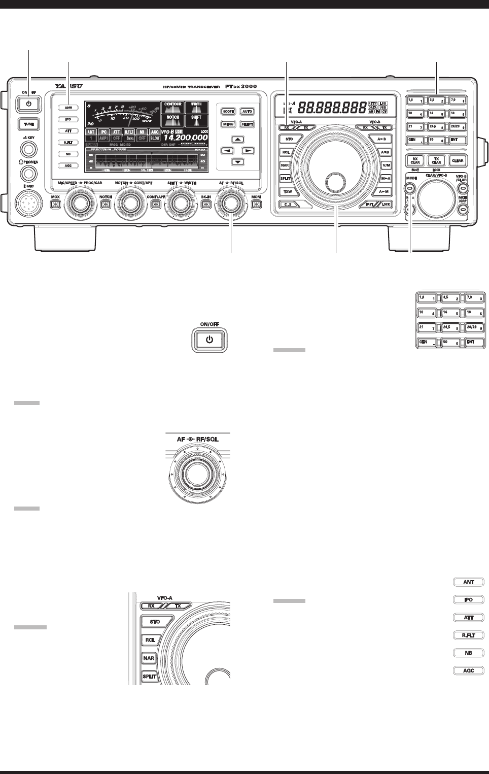
Here is the typical start-up procedure for normal operation:
1. Turn on the external DC power supply.
2. Press and hold in the front-panel [POWER] switch
until the transceiver turns on. After
about five seconds (ten seconds if the
optional µ-Tuning Kit is connected), the
transceiver is ready for full operation.
3. The transceiver will start up on 7.000.00 MHz LSB,
and normal operation may begin.
Note:
To turn power off, press and hold in the front panel
[POWER] switch for two seconds.
4. Rotate the [AF GAIN] knob to set
a comfortable audio level on in-
coming signals or noise. Clockwise
rotation of the [AF GAIN] knob
increases the volume level.
Note:
When using headphones, start by rotating the [AF
GAIN] knob counter-clockwise, then bring the vol-
ume level up after you put the headphones on. This
will minimize the chance of damage to your hearing
caused by an unexpectedly high audio level.
5. Press the [(VFO-A)RX] Indicator/Switch to engage
the VFO-A; the imbedded
LED will glow green.
Advice:
If you press the [(VFO-
A)RX] Indicator/Switch
when the imbedded LED
is already glowing green,
the LED will now blink
“on” and “off”; this indicates that the VFO-A re-
ceiver is temporarily muted. Just press the [(VFO-A)
RX] Indicator/Switch once more to restore VFO-A
receiver operation.
6. Press the [BAND] button corre-
sponding to the Amateur band on
which you wish to begin opera-
tion.
Advice:
One-touch selection of each Amateur band be-
tween 1.8 and 50 MHz is provided.
The FT DX 3000 utilizes a triple band-stack VFO
selection technique, which permits you to store
up to three favorite frequencies and modes onto
each band’s VFO register. For example, you may
store one frequency each on 14 MHz CW, RTTY,
and USB, then recall these frequencies by succes-
sive, momentary presses of the [14] MHz band
button. Each Amateur band button may similarly
have up to three frequency/mode settings applied.
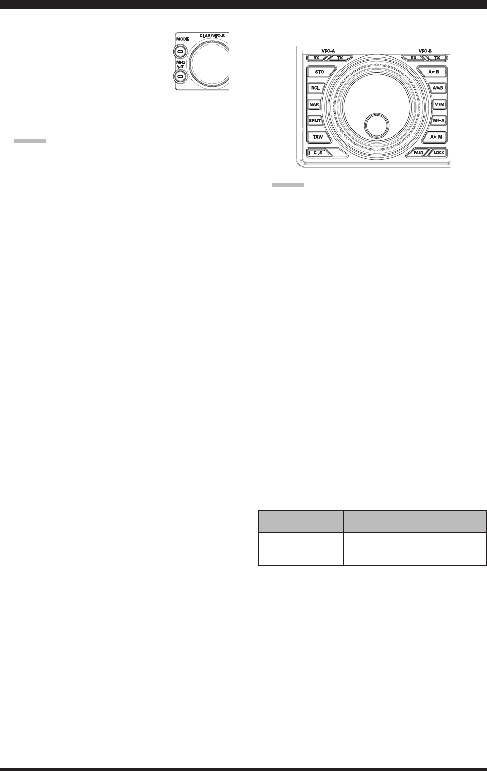
When the [MHz] button (located to the left of the
[CLAR/VFO-B] knob), is pressed, the imbedded
LED will glow orange, and then rotation of the
[CLAR/VFO-B] knob will change the frequency
in 1 MHz steps.
7. Press the [ANT] button to select the ap-
propriate antenna for the band in use.
Advice:
When you make an antenna selection,
that antenna is “remembered” by the
microprocessor in conjunction with the
VFO register in use.
[POWER] Switch
[VFO-A(RX)] Button
[AF GAIN] Knob Main Tuning Dial Knob
[BAND] Button
Basic OperaTiOn:receiving On aMaTeur BanDs
[MODE] Button
[ANT] Switch
FCC ID: K6620461X50 / IC: 511B-20461X50
Page 33FT DX
3000 OperaTing Manual
Basic OperaTiOn:receiving On aMaTeur BanDs
8. Press the [MODE] button to select the desired oper-
ating mode.
Repeated presses this button, step
through the available selections.
Press and hold in the this button, will
toggle to the alternate mode.
For example, In the LSB or USB modes, press and
hold in the this button toggles between “LSB” and
“USB” mode.
Advice:
By convention in the Amateur bands, LSB is
used on the 7 MHz and lower bands (with the
exception of 60 meters), while USB is utilized on
the 14 MHz and higher bands.
When changing modes from SSB to CW, you
will observe a frequency shift on the display.
This shift represents the BFO offset between the
“zero beat” frequency and the audible CW pitch
(tone) you can hear (the pitch is programmed via
the Menu item “055 MODE CW CW PITCH”),
even though the actual tone that you hear is not
changing.
When operating on the FM mode, rotate the
[SQL] (Squelch) knob clockwise to the point
where the background noise is just silenced. This
is the point of maximum sensitivity to weak sig-
nals. Excessive advancement of the [SQL] knob
will degrade the ability of the receiver to detect
weak signals.
You may change the [RF/SQL] knob from the
RF GAIN function to the squelch function via
Menu item “036 GENERAL RF/SQL VR”.
9. Rotate the Main Tuning Dial knob to tune around the
band, and begin normal operation.
Advice:
Clockwise rotation of the Main Tuning Dial knob
increases the operating frequency, one “step”
of the synthesizer at a time; similarly, counter-
clockwise rotation of the Main Tuning Dial knob
will decrease the frequency. Two settings, one
“normal” and one “fast”, are available on each
operating mode. Pressing the [FAST] button
engages the “Fast” tuning selection, see chart be-
low.
It is possible to set the frequency change over one
dial rotation, separately for the CW mode, using
the Menu items “084 TUN DIALSTP” and “085
TUN CW FINE”. See page 116.
If you want to navigate rapidly, so as to effect
rapid frequency change, there are several tech-
niques available:
Direct keyboard entry of the frequency.
Use the [CLAR/VFO-B] knob to tune in 1
MHz steps.
Use the microphone’s [UP]/[DWN] scanning
keys, if your microphone is so equipped.
MAiN tuNiNg diAl KNob tuNiNg RAte
opeRAtiNg Mode 1 step 1 diAl RotAtioN
NoRMAl [FAst] NoRMAl [FAst]
LSB/USB/CW/AM/ 10 Hz 10 kHz
RTTY/PKT(LSB) [100 Hz] [100 kHz]
FM/PKT(FM) 100 Hz [1 kHz]
100 kHz [1 MHz]
[ ] : [FAST] switch set to “ON”
FCC ID: K6620461X50 / IC: 511B-20461X50