Yaesu Musen 20515X20 HH AMATEUR SCANNING RECEIVER User Manual OM
Yaesu Musen Co., Ltd. HH AMATEUR SCANNING RECEIVER OM
Contents
- 1. Operating Manual 1
- 2. Operating Manual 2
- 3. Operating Manual 3
- 4. Operating Manual 4
Operating Manual 3
11
Controls & Connections
FT-70DR/FT-70DE Operating Manual
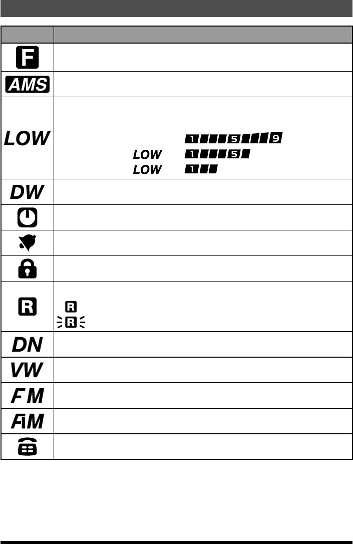
Icon Description of operation
Lights when a function key is pressed (Secondary Keypad Active)
AMS(Automatic Mode Select) Feature Active
TX Power Level Indicator (LOW/MID TX Power Selected)
TX POWER ICON TX Power Meter during
HIGH (5 W) : (disappear)
MID (2 W) :
LOW (0.5 W) :
Dual Watch Active
APO (Automatic Power-Off) Active
Bell Ringer Active
Locking the key and knobs
GM Feature Communication range indicator
:Stations within your communication range
:Stations outside of your communication range (blnk)
V/D mode (simultaneous voice and data communication mode)
Voice FR mode (Voice full-rate mode)
Analog FM mode
AM mode (Receive only)
DTMF Autodialer Active
Application for FCC / IC
FCC ID: K6620515X20, IC: 511B-20515X20
12 FT-70DR/FT-70DE Operating Manual
Installing the Antenna
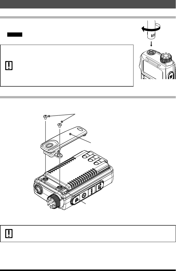
1. Align the bottom side of the antenna with the antenna connector
on the transceiver.
Caution Be sure to hold the thick base of the antenna when installing it.
2. Turn the antenna clockwise until it is secured.
zDo not hold or twist the upper part of the antenna when installing
or removing it. To do so may break the conductors inside the
antenna.
zDo not key the transmit without installing the antenna. The
transmitter components may be damaged.
zWhen using an antenna other than the one supplied, or
connecting to an external antenna, ensure that the SWR is
adjusted to 1.5 or lower.
Attaching the Belt Clip
1. Attach the belt clip on the back of transceiver using the supplied screws (two).
Belt Clip
Supplied Screws
Strap Hole for commercially
available strap
Use a hand strap which can withstand the weight of the transceiver. If you use a hand strap
which is not strong enough, the hand strap can break and the transceiver may fall down,
causing injury, breakage and other troubles.
Preparation
Application for FCC / IC
FCC ID: K6620515X20, IC: 511B-20515X20
13
Preparation
FT-70DR/FT-70DE Operating Manual
Installing the Battery Pack
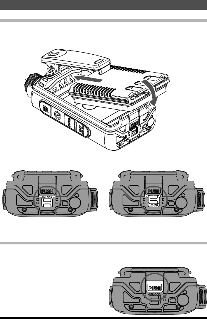
1. Insert the battery pack into the battery compartment on the back of theradio while
tilting the Belt Clip outward.
2. Push the battery pack in until the battery latch clicks securely.
3. Slide the battery pack lock plate to the “UNLOCK” position beside the battery
latch until the entire “LOCK” appears.
Unlock Lock
Removing the Battery Pack
1. To remove the battery pack, turn the radio off and remove any protective cases.
Slide the battery pack lock plate to the “UNLOCK” position.
2. Push the release button (PUSH) while
tilting the Belt Clip outward.
3. Slide the battery downward and out from
the radio while tilting the Belt Clip out of
the way.
Application for FCC / IC
FCC ID: K6620515X20, IC: 511B-20515X20
14 FT-70DR/FT-70DE Operating Manual
If the battery has never been used, or its charge is depleted, it may be charged by
connecting the SAD-11 or SAD-18B Battery Charger, as shown in the illustration, to the
EXT DC jack. It takes about 6 hours to charge the SBR-24LI battery pack fully.
The optional Rapid Charger Cradle (SBH-28) requires about 2.5 hours to charge the SBR-
24LI battery pack.
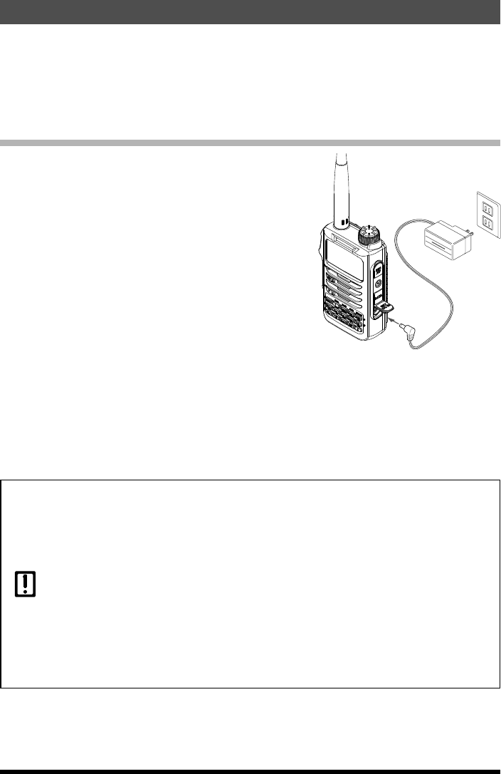
Charging the Battery Pack using the Battery Charger
1. Install the battery pack to the transceiver.
2. Turn the transceiver off.
3. Insert the plug of the battery charger (SAD-11
or SAD-18B) into the EXT DC IN jack of the
transceiver.
Charging starts.
While the battery is being charged, the Mode/
Status Indicator lights red, and the display
indicates “ CHGING”.
The charge level is indicated by bar graph.
It takes about 6 hours to charge the battery
pack fully.
When charging is completed, the display will
change to indicate “CHGFUL” and the lamp
will glow green.
4. When charging is complete, remove the plug
of the battery charger from the jack of the
transceiver.
EXT DC IN
jack
zThe supplied SAD-11 or SAD-18B battery charger is not adequate to operate the transmit
and receive while charging the battery pack.
zCharging may cause noise in a nearby TV or radio.
zCharge the battery pack with the battery charger as far away as possible from a TV or
radio.
zIf “CHGERR” appears on the LCD and the battery pack is not charged after a lapse of 11 or
more hours, stop charging the battery pack immediately.
zIf the same message appears again, the battery pack is presumed to be at the end of its
service life, or defective. In this case, replace the battery pack with a new one.
zWhile charging the battery pack, protect the transceiver from water.
zCharge the battery pack in a place where the ambient temperature is +5 °C to +35 °C
(+41 °F to +95 °F).
zIf the terminal or electrode of the battery case is dirty, this transceiver can malfunction due
to poor contact, resulting in overheating or rupture. If the terminal or electrode gets dirty,
clean it using a dry cloth or cotton swab.
Chraging the Battery Pack
Application for FCC / IC
FCC ID: K6620515X20, IC: 511B-20515X20
15
Chraging the Battery Pack
FT-70DR/FT-70DE Operating Manual
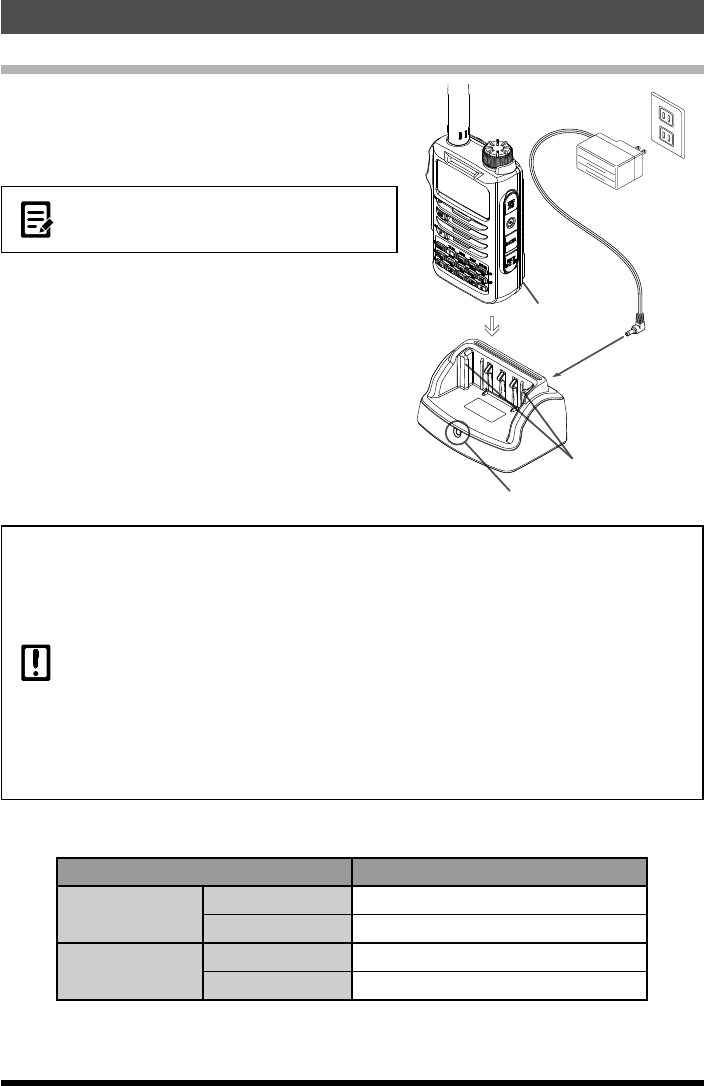
Charging the Battery Pack using the Rapid Charger
1. Insert the plug of the battery charger (SAD-11
or SAD-18B) into the DC IN jack of the rapid
charger (SBH-28).
2. Install the battery pack to the transceiver.
You can charge the battery pack alone (not
attached to the transceiver), by inserting it into
the rapid charger.
3. Turn the transceiver off.
4. Place the transceiver in the rapid charger.
Charging starts.
While the battery is being charged, the lamp
glow red. It takes about 2.5 hours to charge
the battery pack fully.
When charging is completed, the lamp will
glow green.
Lamp RED: Charging
GREEN: Charge Complete
Grooves in
battery pack
(both sides)
Rails
Rapid Charger
SBH-28 (option)
Battery Charger
SAD-11 or SAD-18B
(supplied accessory)
zThe battery pack is rechargeable about 300 times. However, improper use such as
overcharge or over-discharge can shorten its service life.
zThe battery pack is a consumable item. Recharging the battery pack repeatedly will
gradually reduce the charge capacity and duration of its use.
zIf the transceiver is not used for a long period of time with the battery pack installed,
deterioration of the battery pack can accelerate.
zIf the transceiver is unused for a long period of time, be sure to store it with the battery
pack removed.
zWhen the transceiver and battery are stored for an extended period, install the battery pack
biannually and recharge the battery pack about 50% to prevent it from over-discharging.
zStoring the battery pack in a high-temperature environment can accelerate deterioration.
Storethebatterypackinaplacewheretheambienttemperatureis−20°Cto+50°C(−4
°F to +122 °F).
zBe careful not to drop or strongly impact the battery pack. It can break.
Approximate Operating Time
Approximate operating time for the transceiver with the fully charged battery pack.
Band in Use Battery Pack (SBR-24LI)
144 MHz band Digital Mode Approx. 10 hours
Analog Mode Approx. 9 hours
430 MHz band Digital Mode Approx. 8 hours
Analog Mode Approx. 7 hours
Transmission 6 seconds (5 W): Reception 6 seconds (VOL Level 16): Stand By 48
seconds (RX SAVE 1:5)
The operation time that this transceiver can be actually used varies depending on use
conditions, ambient temperature, etc.
Application for FCC / IC
FCC ID: K6620515X20, IC: 511B-20515X20
16
Chraging the Battery Pack
FT-70DR/FT-70DE Operating Manual
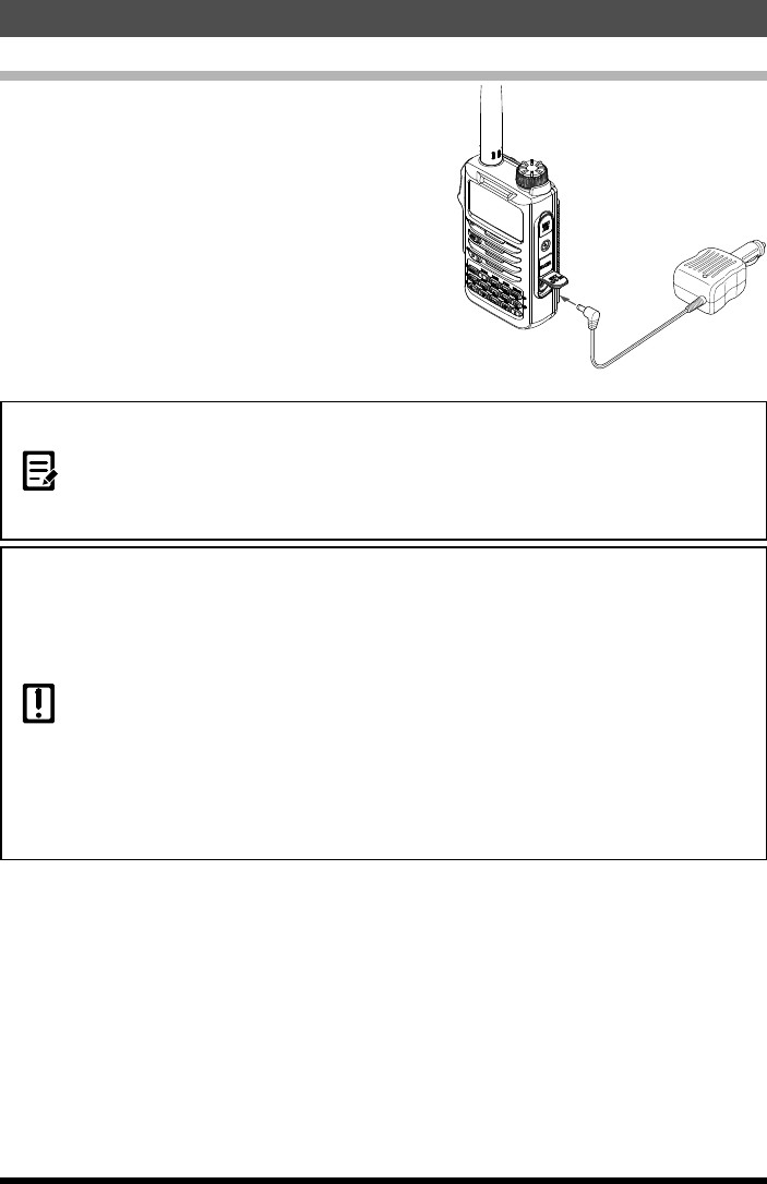
Connecting an External Power Supply for Use in Vehicle
The optional external power supply adapter
with a cigarette lighter plug (SDD-13) allows the
transceiver to be used in a vehicle.
1. Turn off the transceiver.
2. Insert the plug of the external powersupply
adapter with a cigarette lighter plug (SDD-13)
in the EXT DC IN jack of the transceiver.
3. Insert the cigarette lighter plug of theexternal
power supply adapter in the cigarette lighter
socket of the vehicle.
EXT DC IN
jack
External power
supply adapter with
a cigarette lighter plug
SDD-13(optional)
To cigarette lighter
socket of vehicle
zThe SBR-24LI battery pack can be charged in approximately 6 hours using the external
power supply. If the transceiver is turned on while the battery pack is charging, the charging
time will increase slightly.
zCharging stops automatically when the battery pack has been fully charged.
zIf the transceiver is connected to the external power supply with the transceiver turned off,
“EXT DC” appears on the LCD and the display disappears after about 1 minute.
zThe SDD-13 is compatible with a 12 V DC cigarette lighter socket. Do not connect the
SDD-13 to a 24 V DC cigarette lighter socket.
zUse the transceiver at the minimum required transmit power level to prevent overheating.
zDo not continue transmitting for a prolonged period of time. The transceiver may overheat,
resulting in malfunction or burns.
zRecharging the fully-charged battery pack repeatedly can shorten its service life. Be
extremely careful not to continually recharge the battery when operating the transceiver
using an external power supply.
zWhile charging the battery pack, protect the transceiver from water.
zCharge the battery pack in a place where the ambient temperature is +5 °C to +35 °C
(+41 °F to +95 °F).
zIf the terminal or electrode of the battery pack is dirty, the transceiver can malfunction due
to poor contact, resulting in overheating or rupture. If the terminal or electrode gets dirty,
clean it using a dry cloth or cotton swab.
Application for FCC / IC
FCC ID: K6620515X20, IC: 511B-20515X20
17
Chraging the Battery Pack
FT-70DR/FT-70DE Operating Manual
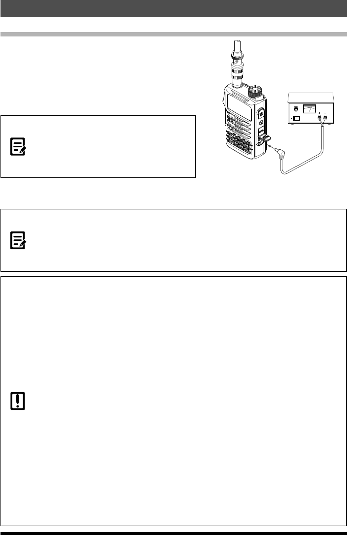
Connecting to an External Power Supply Using a Power Cable
The optional power cable (E-DC-6) allows the
transceiver to be connected to an external power
supply.
1. Turn off the transceiver.
2. Connect the optional external power supply
cable (E-DC-6) to an external power supply.
zConnect the red/black wire or white/red wire
to the positive (+) terminal of the external
power supply and the black wire to the
negative(−)terminal.
z Set the voltage of the external power
supply at 12 to 14 V.
3. Insert the plug of the external power supply
into the EXT DC IN jack of the transceiver.
External power supply
EXT DC IN
jack
External power
supply cable E-DC-6
(optional)
Connect the external
antenna.
zThe SBR-24LI battery pack can be charged in approximately 6 hours using the external
power supply. If the transceiver is turned on while the battery pack is charging, the charging
time will increase slightly.
zCharging stops automatically when the battery pack has been fully charged.
zIf the transceiver is connected to the external power supply with the transceiver turned off,
“EXT DC” appears on the LCD and the display disappears after about 1 minute.
zWhen using the transceiver with the external power supply cable (E-DC-6) connected to an
external power supply, pay attention to the following:
•Thepowersupplyvoltagemustbebetween12Vand14V.
If the voltage exceeds 16 V, malfunctions and damage to the electric circuits of the transceiver
may result. Take extra care.
•Connectthered/blackwireorwhite/blackwireoftheexternal powersupplycable (E-DC-6)
tothepositive(+)terminaloftheexternalpowersupplyandtheblackwiretothenegative(−)
terminal.
•Useanexternalpowersupplyhavingsufficientcurrentcapacity(3Aormore).
•Ifthetransceiveris usedwiththesuppliedantennaconnected,thetransmitRFmayinterfere
with the external power supply, resulting in malfunction or failure. When using an external power
supply, remove the supplied antenna and connect an external antenna. Place the external
power supply sufficiently away from the transceiver to avoid RF interference.
zUse the transceiver at the minimum required transmission power level to prevent overheating.
zDo not continue transmitting for a prolonged period. The transceiver may overheat, resulting in
malfunction or a burn injury.
zRecharging the fully-charged battery pack repeatedly can shorten its service life. Be extremely
careful not to continually recharge the battery when operating the transceiver using an external
power supply.
zWhile charging the battery pack, protect the transceiver from water.
zCharge the battery pack in a place where the ambient temperature is +5 °C to +35 °C (+41 °F to
+95 °F).
zIf the terminals or electrodes of the battery pack are dirty, the transceiver may malfunction due to
poor contact, resulting in overheating or rupture. If the terminals or electrodes get dirty, clean them
using a dry cloth or cotton swab.
Application for FCC / IC
FCC ID: K6620515X20, IC: 511B-20515X20
18 FT-70DR/FT-70DE Operating Manual
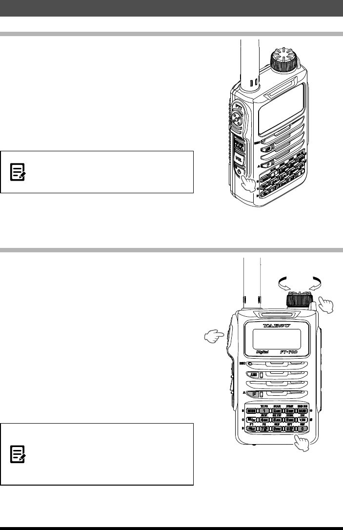
Turning on the Transceiver
1. Press and hold [POWER] switch.
When the transceiver is turned on for the first
time after purchase, the call sign input message
appears on the LCD.
The next time, the frequency screen will appear
after the opening screen.
When the transceiver is turned on the second
time, and subsequently, the frequency screen
appears.
zBe sure to set the call sign ID using the
FT-70DR/DE.
zThe Call Sign ID can be changed using the
set mode [76 MYCALL].
●Turning off the Transceiver
To turn the transceiver OFF, press and hold
[POWER] switch.
Inputing the call sign
1. Input a callsign for your transceiver.
Input the callsign with the ten key or DIAL
knob.
Example 1:
Press the [2] key repeatedly to toggle among
the four available characters associated with
that key:
A→B→C→2→A→···
Example 2:
Rotate the DIAL knob to select any of the 38
available characters.
0~9↔A~Z↔(space)↔‒↔⁄↔···
2. Press [F] key or [PTT] switch to save the
inputted call sign.
zUp to 10 characters (letters, numbers, a
hyphen and a slash) can be entered.
zPress [MODE] key / [BAND] key to move
the cursor to left / right in the text input area.
zPress and hold [GM] key to delete all
characters after the cursor.
Basic Operation
Application for FCC / IC
FCC ID: K6620515X20, IC: 511B-20515X20
19
Basic Operation
FT-70DR/FT-70DE Operating Manual
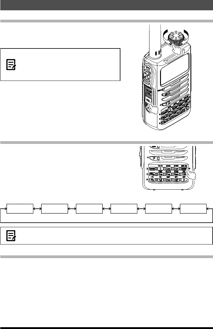
Adjusting the Volume Level
1. Rotate the DIAL knob while pressing and
holding the key to set the desired audio level.
Clockwise rotation increases the volume level.
z If no sound is heard from the speaker, press
and then adjust the volume level while
listening to white noise.
zPress [F] key, then press the [MONI]
(T-CALL) Key to adjust the squelch level.
Selecting a Frequency Band
1. Press the [BAND] key to select the desired
frquency band.
Frequency bands
Information
radio band (1)
144 MHz band 430 MHz band
Information
radio band (3)
AIR band
Information
radio band (2)
108 - 137 MHz 137 - 174 MHz 174 - 222 MHz 222 - 420 MHz 420 - 470 MHz 470 - 580MHz
z Press [F] key, then press the [BAND] key to switch the frequency bands in reverse order.
zTo recall the HOME channel of each frequency band touch [HM/RV] key.
Tuning to a Frequency
Tune in to your desired frequency using either of the following methods:
●Rotate the DIAL to tune to the desired frequency
1. Press the [V/M] key to switch the transceiver to VFO mode.
2. Rotate the [DIAL] knob to tune to the desired frequency.
Rotate clockwise: The frequency increases.
Rotate counterclockwise: The frequency decreases.
By pressing [F] key and rotating the [DIAL] knob, the frequency will change in
1 MHz steps Entering.
Application for FCC / IC
FCC ID: K6620515X20, IC: 511B-20515X20
20
Basic Operation
FT-70DR/FT-70DE Operating Manual
zIn factory settings, Auto Step mode is set so that the transceiver is automatically switched to
the optimal frequency steps for the receiver frequency.
zIn factory settings, turning the [DIAL] knob beyond the selected frequency band causes the
transceiver to switch to the next frequency band.
To change the tuning so the frequency will move repeatedly through the selected band,
enter the Set mode, then select [74 VFO.MOD] and select “BAND”.
●Entering the frequency directly using the numeric keys
1. Press the [V/M] key to switch the transceiver to VFO mode.
2. Enter the desired frequency using numeric keys.
Examples:
To enter 145.520 MHz, press [1]→[4]→[5]→[5]→[2]
To enter 430.000 MHz, press [4]→[3]→[V/M] (or press and hold [0])
zIf a wrong digit is entered when entering a frequency using the numeric keys, it may be
canceled by pressing [PTT] switch.
Selecting the Communication Mode
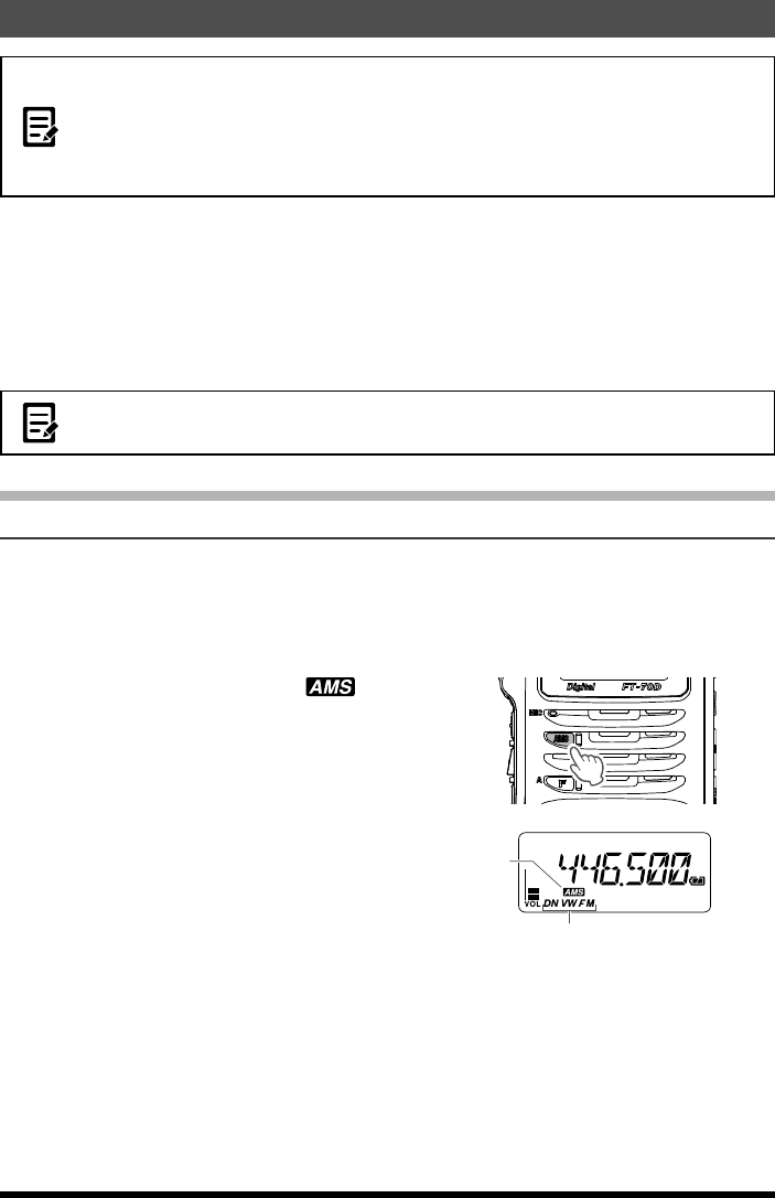
Using AMS(Automatic Mode Select)
The FT-70DR/DE transceiver is equipped with the AMS (Automatic Mode Select)
function which automatically selects from two modes of transmission corresponding to
the signal being received.
The transmit mode is selected according to the received signal so that C4FM digital
signals, and analog signals are received and transmitted automatically.
1. Press [AMS] key to display “ ” icon on
the LCD.
Displays the communication mode (radio wave
type).
DN : V/D Mode (Voice/Data simultaneous
transmission mode)
VW : Voice FR Mode (Voice Full Rate Mode)
FM : Analog FM Mode
Current Communication Mode
AMS icon
●Setting the transmission mode when using the AMS function
1. Press the [AMS] key to active the AMS function.
2. Press and hold [AMS] key.
3. Rotate the [DIAL] knob to tune to the desired communication mode as follows.
Application for FCC / IC
FCC ID: K6620515X20, IC: 511B-20515X20