Yaesu Musen 20515X20 HH AMATEUR SCANNING RECEIVER User Manual OM
Yaesu Musen Co., Ltd. HH AMATEUR SCANNING RECEIVER OM
Contents
- 1. Operating Manual 1
- 2. Operating Manual 2
- 3. Operating Manual 3
- 4. Operating Manual 4
Operating Manual 4
21
Basic Operation
FT-70DR/FT-70DE Operating Manual
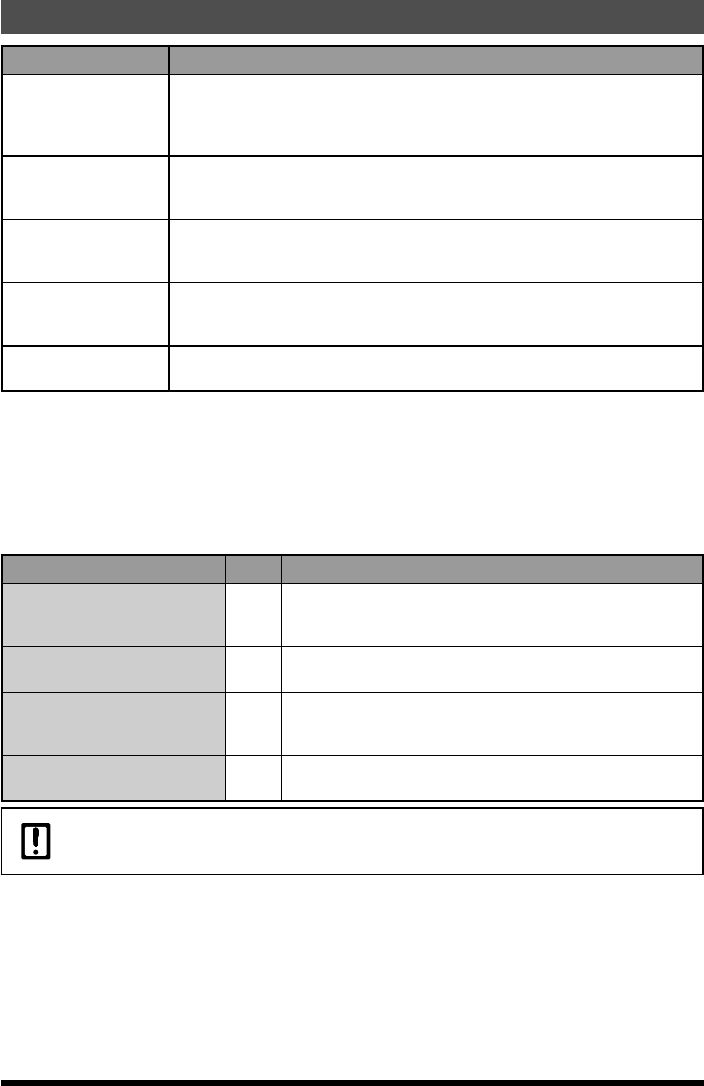
Transmit mode Description of Modes
MANUAL
Automatically selects one of the 4 communication modes according to the
received signal.
Briefly pressing [PTT] switche between digital mode (DN) and analog FM
mode.
FM FIX
Automatically selects one of the 4 communication modes according to the
received signal.
Always switches to FM mode for transmission.
DN FIX
Automatically selects one of the 4 communication modes according to the
received signal.
Always switches to DN mode for transmission.
VW FIX
Automatically selects one of the 4 communication modes according to the
received signal.
Always switches to VW mode for transmission.
AUTO Automatically selects one of the 4 communication modes according to the
received signal.
4. Press [PTT] switch to save the setting and return to normal operation.
●Changing the communication mode manually
1. Press the [AMS] key to deactivate the AMS function.
2. Pressing repeatedly switches the communication mode as follows. Pressing [mode]
key repeatedly switches the communication mode as follows.
[Digital(DN)]→[DigitalWide(VW)]→[Analog(FM)]→···
Communication Mode Icon Explanation of modes
V/D Mode
(Voice/Data simultaneous
transmission mode) DN Calls are less prone to interruptions due to detection
and correction of voice signals during digital voice signal
transmission. This is the standard mode for C4FM Digital.
Voice FR Mode
(Voice Full Rate Mode) VW High speed data communication using entire 12.5 kHz
band. Enables high-quality voice communication.
Analog FM Mode FM Analog communication using FM mode.
Effective when the signal is weak and audio is susceptible
tointerruption in digital mode.
AM Mode (receive only) AM The FT-70DR/DE is mainly provides the AM mode for
reception of air band.
In V/D mode (“DN” on the LCD), position information is included in the radio wave during voice
communication, however, position information is not included in the Voice FR mode (“VW” on the
LCD).
Application for FCC / IC
FCC ID: K6620515X20, IC: 511B-20515X20
22
Basic Operation
FT-70DR/FT-70DE Operating Manual
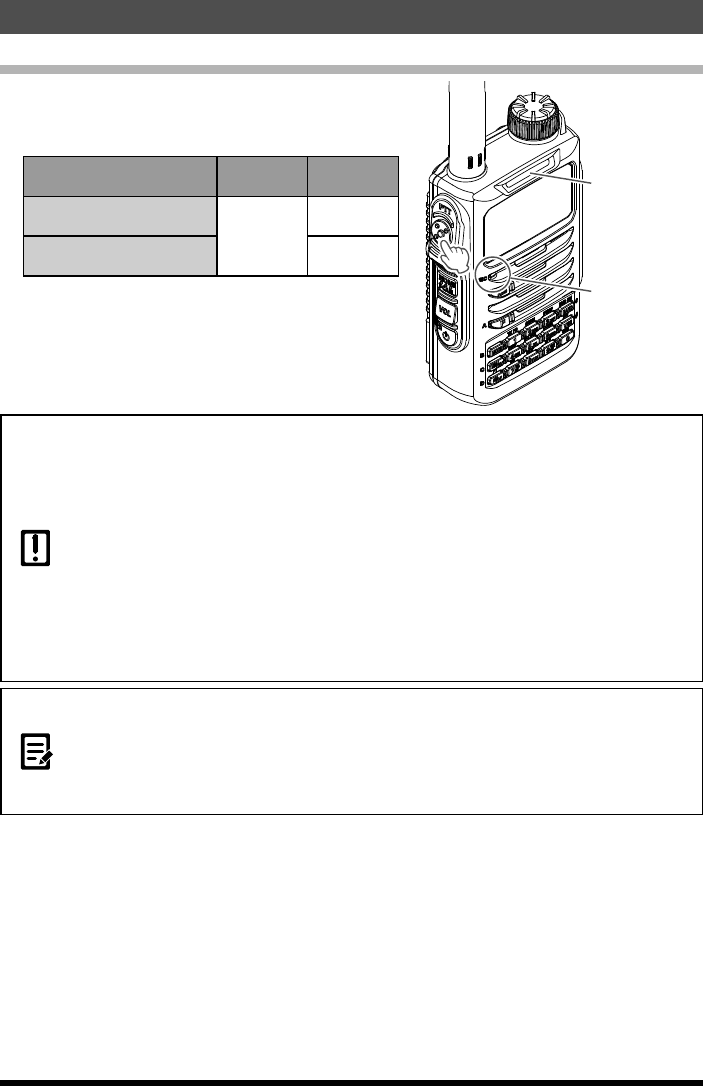
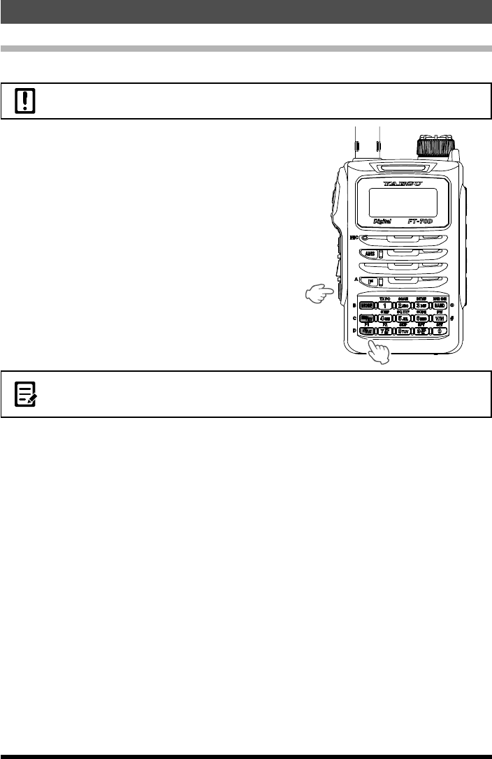
Transmission
1. Press and hold [PTT] switch on the microphone.
The Mode/Status Indicator lights up as shown
in the table below during transmission.
Communication mode Left
portion Right
portion
Analog FM
Red
Red
V/D mode /
Voice FR mode Blue
Keep your mouth about 5 cm away from the
microphone when you speak.
2. Release [PTT] switch.
The transceiver returns to receive mode.
Microphone
Mode/Status
Indicator
zUse the transceiver at the minimum required transmit power level. Doing so prevents the
transceiver from overheating and saves battery power, increasing the operating time.
zDo not continue transmitting for a prolonged period. The transceiver can overheat, resulting
in malfunction or a burn injury.
zIf transmission is continued for a long period, the transceiver overheats and the high
temperature protection function is activated. As a result, the transmitting power level is
automatically set to Low Power. If you continue transmitting while the high temperature
protection function is active, the transceiver will be forcibly returned to the receive mode.
zIf you touch the transceiver immediately after the high temperature protection function has
become active, you may be burned. Wait for the temperature inside the transceiver to cool
sufficiently before resuming transmission.
zDo not start transmitting without attaching the antenna. The transmitter circuit can be
damaged.
zYou can transmit on the 144 MHz and 430 MHz ham radio bands.
zEven while receiving in AM mode, transmit will continue to be in NFM mode when pressing .
zIf is pressed when a frequency other than the amateur ham radio band is selected, an alarm
tone (beep) will be emitted and “ERROR” appears on the LCD, disabling transmission.
zThe transceiver may be set to inhibit transmit while receiving a signal. Press and hold [F]
key to enter the Set mode, then select [4 BCLO], and then select [ON].
Application for FCC / IC
FCC ID: K6620515X20, IC: 511B-20515X20
23
Basic Operation
FT-70DR/FT-70DE Operating Manual
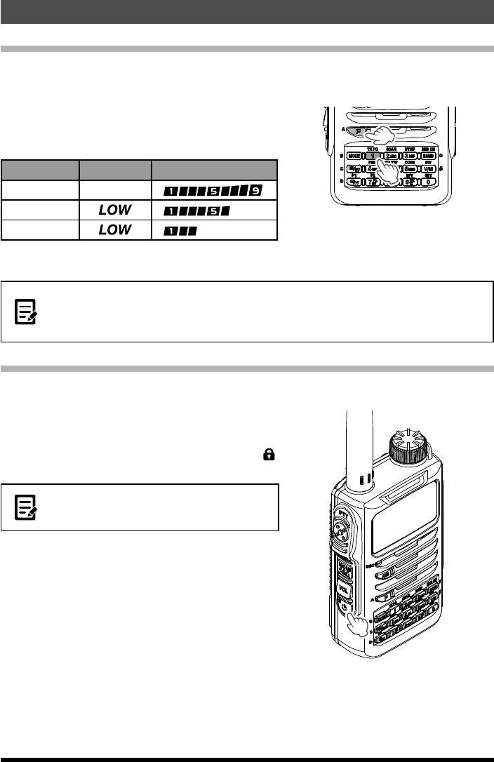
Changing the Transmission Power Level
The maximum transmit power level of this transceiver is 5 W. When communicating with
another station in the immediate area, or to reduce the battery power consumption, the
transmit power level may be lowered.
1. Press [F] key, then press the [1](TX PO) key.
2. Rotate the [DIAL] knob to select one of the
following transmission power levels.
TX PO Level Icon PO meter
HIGH (5 W) (disappear)
MID (2 W)
LOW (0.5 W)
3. Press [PTT] switch to save the setting and
return to normal operation.
zThe transmitter power level may be set separately for the 144 MHz and 430 MHz band.
zUse the transceiver at the minimum required transmit power level to reduce battery power
consumption.
zBy default, “HIGH (High power)” is selected.
Locking Keys and Dial
To prevent accidental frequency change during operation, the keys, switches and DIAL
(except [MONI] key and [VOL] key) can be locked.
1. Press and hold [LOCK](POWER) key.
“LOCK” is displayed for 1 second on the LCD.
When the lock function is activated, “”
always appears on the LCD.
To lock/unlock the operations of the DIAL konob
and [PTT] switch, press and hold the [F] key to
enter Set mode, then select [38 LOCK].
2. To unlock a key or dial, press and hold [LOCK]
(POWER) key again.
“UNLOCK” is displayed on the LCD for 1
second.
Application for FCC / IC
FCC ID: K6620515X20, IC: 511B-20515X20
24
Basic Operation
FT-70DR/FT-70DE Operating Manual
Communicating Via the Repeater
The FT-70DR/DE includes an ARS (Automatic Repeater Shift) function which enables
repeater operation automatically when setting the receiver to the repeater frequency.
1. Set the receiver frequency to the repeater frequency.
“” or “ ” appears in the above of the frequency.
2. Begin transmitting by pressing and holding [PTT] switch. The transmitter will
automatically be set to the programmed offset frequency.
zPressing [F] key and then pressing [HM/RV] key enters the “reverse” state where the
transmission frequency and the receive frequency are temporarily reversed. This allows
checking to find if direct communication with the remote station is possible.
zIn the “reverse” state, “” or “ ” blinks on the LCD.
zPressing [F] key again and then [HM/RV] exits from the “reverse” state.
zPress and hold [F] key to enter Set mode, then configure the following repeater settings for
more convenient use.
[54 RPT.ARS]: Deactivates the ARS function
[55 RPT.FRQ]: Allows changing the repeater shift offset
[56 RPT.SFT]: Allows setting the repeater shift direction
Tone Calling (1750 Hz burst tone)
If your transceiver is FT-70DE (European version), press and hold in the [MONI/
T-CALL] key to generates a 1750 Hz burst tone to access the European repeater.
The transmitter will automatically be activated, and a 1750 Hz audio tone will be
superimposed on the carrier. Once access to the repeater has been gained, you may
release the [MONI/T-CALL] key, and use the [PTT] switch for activating the transmitter
thereafter. If you need to access the repeaters which requires a 1750 Hz burst tone
for access by the FT-70DR (USA/EXP versions), you can set the [MONI/T-CALL] key
switch to serve as a “Tone Call” switch instead. To change the configuration of this
switch, use Set Mode [40 M/T-CL].
Application for FCC / IC
FCC ID: K6620515X20, IC: 511B-20515X20
25
Basic Operation
FT-70DR/FT-70DE Operating Manual
Restoring to Defaults (All Reset)
To restore all transceiver settings and memory content to the defaults.
When the All Reset function is performed, all data registered in the memory will be deleted. Be
sure to note the settings on paper.
1. Turn the radio OFF.
2. Press and hold [MODE] key, [HM/RV] key
and [GM] key and turn on the transceiver
simultaneously.
3. When the beep sounds, release the key.
“ALL RESET? PUSH F KEY” appears on the
LCD.
4. Touch [F] key.
A beep sounds and the call sign input
message appears on the LCD.
z To cancel Reset function, press a key or switch other than [F] key.
zTo return only the Set Mode option settings to default, Press and hold [MODE] key and [V/M]
key and turn on the transceiver simultaneously.
Application for FCC / IC
FCC ID: K6620515X20, IC: 511B-20515X20

26 FT-70DR/FT-70DE Operating Manual
●General
Frequency range: TX 144 - 146 MHz or 144 - 148 MHz
430 - 440 MHz or 430 - 450 MHz
RX 108 - 137 MHz (Air Band)
137 - 174 MHz (144 MHz HAM)
174 - 222 MHz (GEN1)
222 - 420 MHz (GEN2)
420 - 470 MHz (430 MHz HAM)
470 - 579.995 MHz (GEN3)
Channel steps: 5 / 6.25 / 8.33 / 10 / 12.5 / 15 / 20 / 25 / 50 / 100 kHz
(8.33 kHz : only for Air band)
Emission Type: F2D, F3E, F7W
Frequency stability: ±2.5ppm−4°Fto+140°F(−20°Cto+60°C)
Antenna impedance: 50Ω
Supply Voltage: Nominal 7.4 V DC, negative ground
Operating 6 - 14 V DC Negative Ground (EXT DC JACK while Charging)
11 - 16 V DC Negative Ground (EXT DC JACK with SDD-13)
Current consumption: 120 mA (Receive)
80 mA (Standby, Save Off)
50 mA (Standby, Saver On “Save Ratio 1:5”)
+20 mA (Digital or AMS)
400μA(AutoPowerOff)
1.6 A (5 W TX, 144 MHz 7.4 V DC)
1.8 A (5 W TX, 430 MHz 7.4 V DC)
Operating temperature: −4°Fto+140°F(−20°Cto+60°C)
Case size: 2.4" (W) × 3.6" (H) × 1.6" (D) (60 × 98 × 32 mm)
Weight (approx.): 9.5 oz (270 g) with SBR-24LI, Antenna
●Transmitter
Output Power: 5 W (High) / 2.5 W (Mid) / 0.5 W (LOW)
(@ 7.4 V DC or EXT DC)
Modulation Type: F2D, F3E: Variable Reactance Modulation
F7W: 4FSK (C4FM)
Spurious Emission: USA/EXP version
At least 60 dB below (@TX Power High, Mid)
At least 40 dB below (@TX Power Low)
●Receiver
Circuit Type: Double-conversion super heterodyne
Intermediate Frequency: 1st: 47.25 MHz
2nd: 450 kHz
Sensitivity: 1.5
μ
V for 10 dB SN (108 - 137 MHz, AM)
0.2
μ
V for 12 dB SINAD (137 - 140 MHz, NFM)
0.16
μ
V for 12 dB SINAD (140 - 150 MHz, NFM)
0.2
μ
V for 12 dB SINAD (150 - 174 MHz, NFM)
1
μ
V for 12 dB SINAD (174 - 222 MHz, NFM)
0.5
μ
V for 12 dB SINAD (300 - 350 MHz, NFM)
0.2
μ
V for 12 dB SINAD (350 - 400 MHz, NFM)
Specifications
Application for FCC / IC
FCC ID: K6620515X20, IC: 511B-20515X20
27
Specifications
FT-70DR/FT-70DE Operating Manual
0.18
μ
V for 12 dB SINAD (400 - 470 MHz, NFM)
1.5
μ
V for 12 dB SINAD (470 - 579.995 MHz, NFM)
0.19
μ
V TYP for BER 1% (Digital Mode)
Selectivity(−6dB/−60dB): 12 kHz / 35 kHz (NFM/AM)
AF Output: 700mW(16Ωfor10%THD7.2V)internalspeaker
300mW(8Ωfor10%THD7.2V)externalspeaker
Rated values are at normal temperature and pressure.
Specifications are subject to change without notice, and are guaranteed within the 144/430 MHz amateur
bands only. Frequency ranges will vary according to transceiver version; check with your dealer.
Disposal of your Electronic and Electric Equipment
Products with the symbol (crossed-out wheeled bin) cannot be disposed as house-
hold waste.
Electronic and Electric Equipment should be recycled at a facility capable of handling
these items and their waste by products.
In EU countries, please contact your local equipment supplier representative or ser-
vice center for information about the waste collection system in your country.
Attention in case of use
This transceiver works on frequencies which are not gen-
erally permitted.
As for the actual usage, the user has to possess an ama-
teur radio licence.
Usage is allowed only in the frequency bands which are
allocated for amateur radios.
List of national codes
AT BE BG CY CZ DE
DK ES EE FI FR GB
GR HR HU IE IT LT
LU LV MT NL PL PT
RO SK SI SE CH IS
LI NO – – – –
Application for FCC / IC
FCC ID: K6620515X20, IC: 511B-20515X20

28 FT-70DR/FT-70DE Operating Manual
zChanges or modifications to this device that are not expressly approved by YAESU MUSEN could
void the user’s authorization to operate this device.
zThis device complies with part 15 of the FCC Rules. Operation is subject to the following two
conditions: (1) This device may not cause harmful interference, and (2) this device must accept any
interference including received, interference that may cause undesired operation.
zThe scanning receiver in this equipment is incapable of tuning, or readily being altered, by the User
to operate within the frequency bands allocated to the Domestic public Cellular Telecommunications
Service in Part 22.
zTheYAESUMUSENisnotresponsibleforanycangesormodicationsnotexpresslyapprovedby
thepartyresponsibleforcompliance.Suchmodivationsscouldvoidtheuser’sauthoritytooperate
the equipment.
zTheYAESUMUSENisnotresponsibleforanychangesormodicationsnotexpresslyapprovedby
thepartyresponsibleforcompliance.Suchmodicationscouldvoidtheuser’sauthoritytooperate
the equipment.
This device complies with Industry Canada license-exempt RSS standard(s). Operation is subject
to the following two conditions: (1) this device may not cause interference, and (2) this device must
accept any interference, including interference that may cause undesired operation of the device.
Le présent appareil est conforme aux CNR d’Industrie Canada applicables aux appareils radio
exempts de licence. L’exploitation est autorisée aux deux conditions suivantes : (1) l’appareil ne doit
pas produire de brouillage, et (2) l’utilisateur de l’appareil doit accepter tout brouillage radioélectrique
subi, même si le brouillage est susceptible d’en compromettre le fonctionnement.
DECLARATION BY MANUFACTURER
The Scanner receiver is not a digital scanner and is incapable of being converted or modified to a
digital scanner receiver by any user.
WARNING: MODIFICATION OF THIS DEVICE TO RECEIVE CELLULAR RADIOTELEPHONE
SERVICE SIGNALS IS PROHIBITED UNDER FCC RULES AND FEDERAL LAW.
CAN ICES-3 (B) / NMB-3 (B)
This equipment has been tested and found to comply with the limits for a Class B digital device,
pursuant to part 15 of the FCC Rules. These limits are designed to provide reasonable protection
against harmful interference in a residential installation. This equipment generates uses and can
radiate radio frequency energy and, if not installed and used in accordance with the instructions,
may cause harmful interference to radio communications. However, there is no guarantee that
interference will not occur in a particular installation.
If this equipment does cause harmful interference to radio or television reception, which can
be determined by turning the equipment off and on, the user is encouraged to try to correct the
interference by one or more of the following measures:
r Reorient or relocate the receiving antenna.
r Increase the separation between the equipment and receiver.
r Connect the equipment into an outlet on a circuit different from that to which the receiver is
connected.
r Consult the dealer or an experienced radio/TV technician for help.
Application for FCC / IC
FCC ID: K6620515X20, IC: 511B-20515X20

29FT-70DR/FT-70DE Operating Manual
Application for FCC / IC
FCC ID: K6620515X20, IC: 511B-20515X20
Copyright 2016
YAESU MUSEN CO., LTD.
All rights reserved.
No portion of this manual
may be reproduced
without the permission of
YAESU MUSEN CO., LTD.
1611X-AO
Printed in Japan
YAESU MUSEN CO., LTD.
Tennozu Parkside Building
2-5-8 Higashi-Shinagawa, Shinagawa-ku, Tokyo 140-0002 Japan
YAESU USA
6125 Phyllis Drive, Cypress, CA 90630, U.S.A.
YAESU UK
Unit 12, Sun Valley Business Park, Winnall Close
Winchester, Hampshire, SO23 0LB, U.K.
Application for FCC / IC
FCC ID: K6620515X20, IC: 511B-20515X20