Yaesu Musen 30453X20 PORTABLE MARINE TRANSCEIVER User Manual HX290 pmd
Yaesu Musen Co., Ltd. PORTABLE MARINE TRANSCEIVER HX290 pmd
UserManual.wiki
>
Yaesu Musen
>
30453X20 User Manual
Users Manual
Navigation menu
Upload a User Manual
Namespaces
Wiki Guide
HTML
PDF
Info
Views
User Manual
Discussion / Help
Navigation
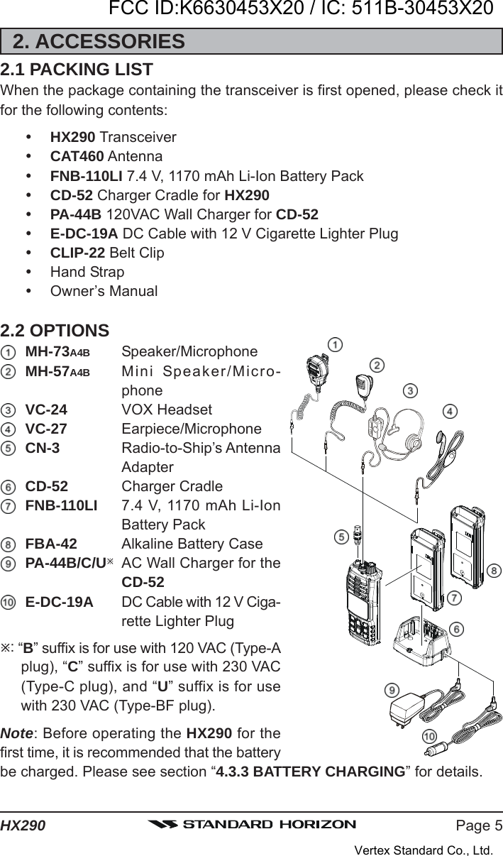
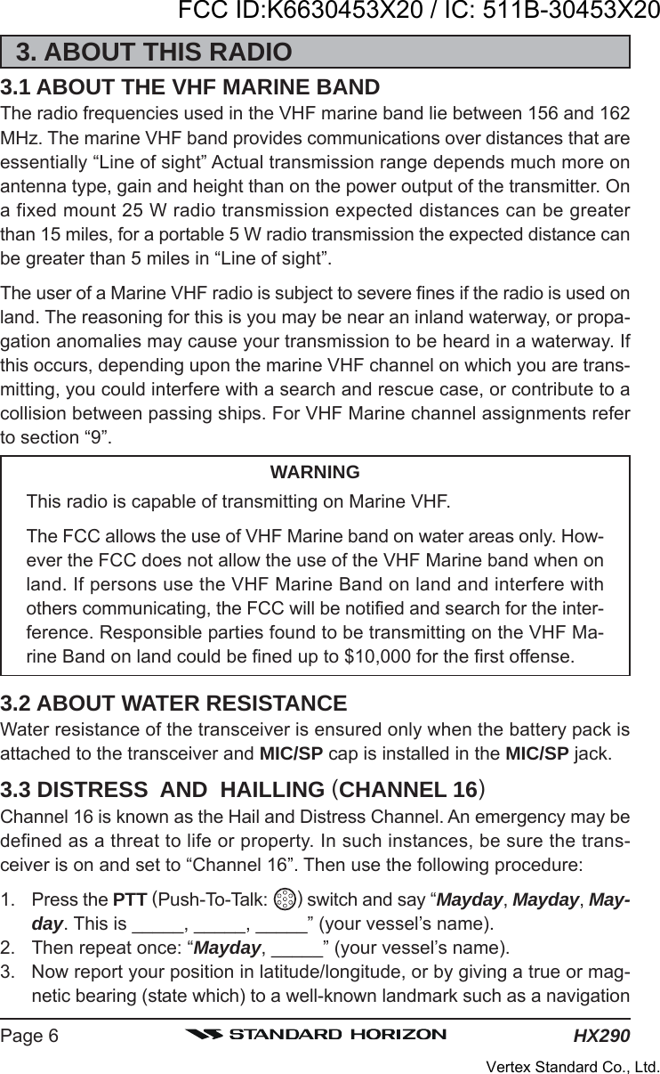
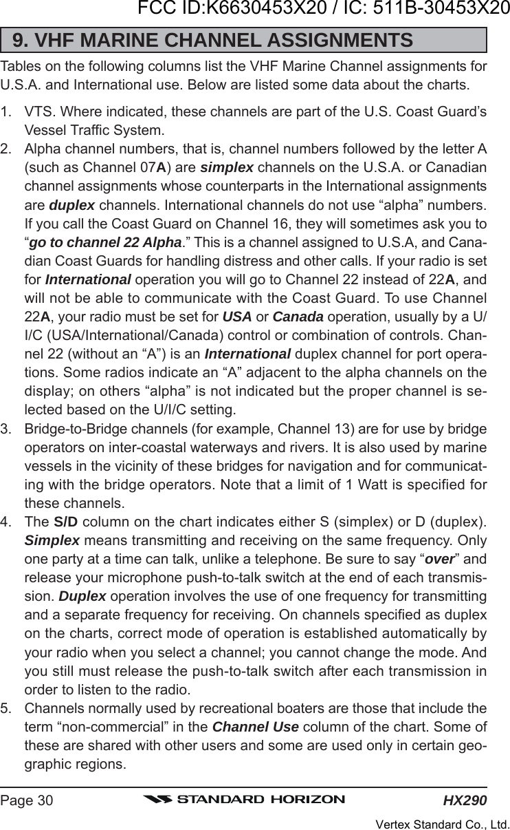
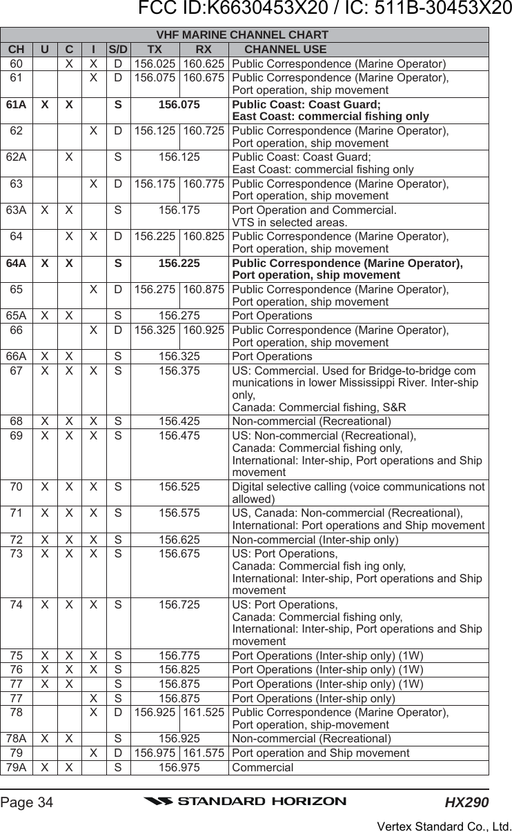
![Page 3HX290QUICK REFERENCE GUIDEThis transceiver is equipped with the E2O (Easy-To-Operate) system. You cando the basic operation in numerical order of the illustration below. [PWR/VOL] KNOBRotate this knobclockwise to turn onthe radio, and adjustthe audio level. [SQL] BUTTONPress this key first,then press the []key to squelch orpress the [] key toun-squelch the radio. []/[] BUTTONSSelects the operatingchannel.MICWhen transmitting,position your mouth1 inch (2.5 cm) awayfrom the small michole.Speak slowly andclearly into the micro-phone. [16/9] BUTTONPress to recallchannel 16.Press and hold torecall channel 9. [H/L()] BUTTONPress to toggle thetransmit power be-tween High (5W) andLow (1W). [PTT] SWITCHSpeak into the micro-phone in a normalvoice level whilepressing this switch.NOTEFor additional details, refer to next page or section “5. CONTROLS ANDINDICATORS”.FCC ID:K6630453X20 / IC: 511B-30453X20Vertex Standard Co., Ltd.](https://usermanual.wiki/Yaesu-Musen/30453X20/User-Guide-1413161-Page-3.png)
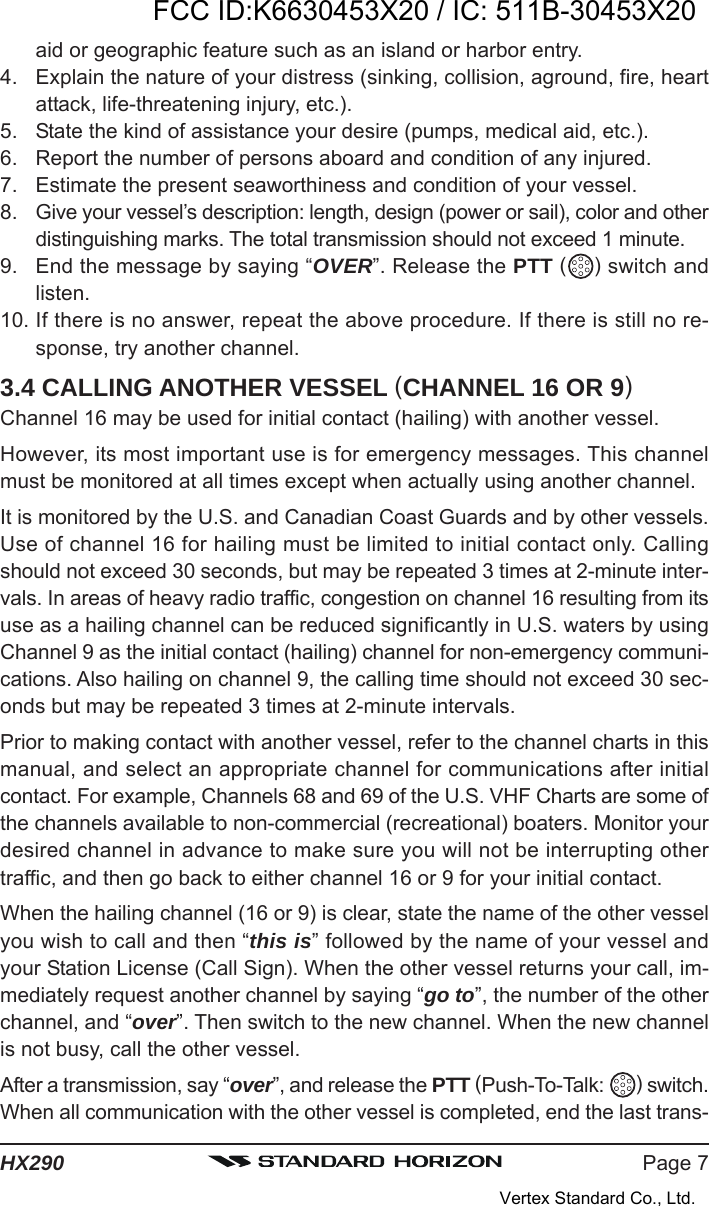


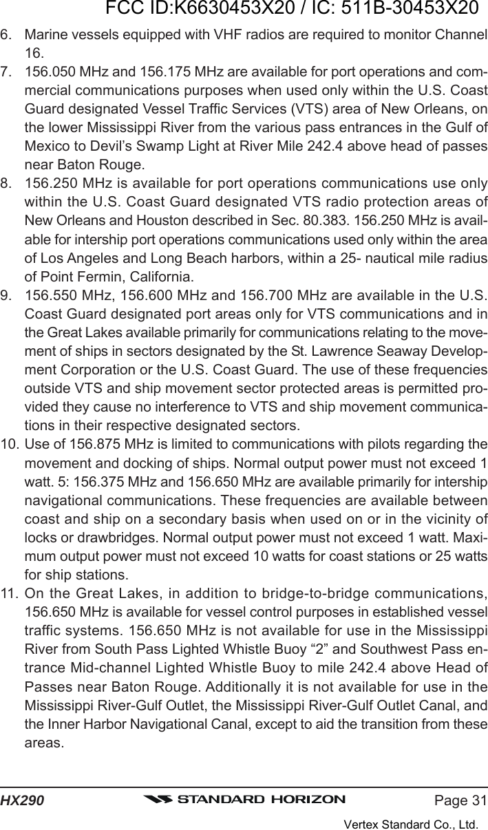

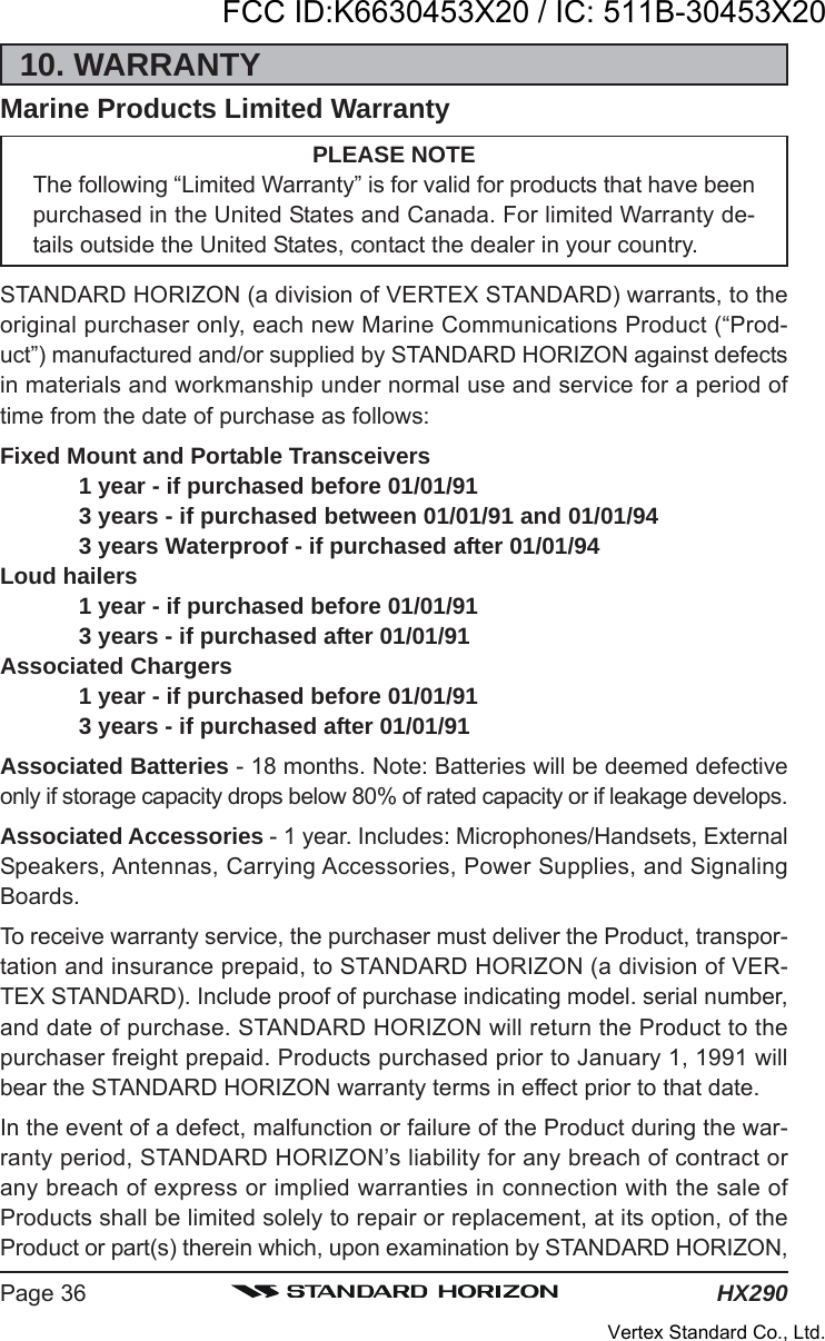
![HX290Page 4012. SPECIFICATIONSPerformance specifications are nominal, unless otherwise indicated, and aresubject to change without notice.12.1 GENERALFrequency Ranges: TX: 156.025 MHz - 157.425 MHzRX: 156.050 MHz - 163.275 MHzChannel Spacing: 25 kHzFrequency Stability: ±5 ppm(–4 °F to +140 °F [–20 °C to +60 °C])Emission Type: 16K0G3EAntenna Impedance: 50 Supply Voltage: 7.4V DC, Negative Ground(Battery Terminal)Current Consumption: 320 mA (Receive, Typical at AF MAX.)50 mA (Standby)1.6 A / 0.7 A (TX: 5 W / 1W)Operating Temperature: –4 °F to +140 °F (–20 °C to +60 °C)Case Size (W x H x D): 2.24” x 5.24” x 1.73” (57 x 133 x 44 mm)(w/o knob & antenna)Weight (Approx.): 10.9 oz (310 g)(w/FNB-110LI, Belt Clip, & Antenna)12.2 TRANSMITTERRF Power Output: 5 W / 1 W (@7.4 V )Modulation Type: Variable ReactanceMaximum Deviation: ±5 kHzSpurious Emission: –75 dBc typicalMicrophone Impedance:2 k12.3 RECEIVERCircuit Type: Double-Conversion SuperheterodyneIntermediate Frequencies: 1st: 21.7 MHz, 2nd: 450 kHzAdjacent Channel Selectivity: 70 dB typicalIntermodulation: 68 dB typicalHum & Noise Ratio: 40 dB typicalSensitivity: 0.25 μV for 12 dB SINADSelectivity: 25 kHz (–70 dB)AF Output (Internal SP): 700 mW @16 for 10 % THD (@7.4 V)Measured in accordance with TIA/EIA-603.FCC ID:K6630453X20 / IC: 511B-30453X20Vertex Standard Co., Ltd.](https://usermanual.wiki/Yaesu-Musen/30453X20/User-Guide-1413161-Page-40.png)