Yaesu Musen 30483X3D MARINE TRANSCEIVER User Manual GX1600 Owner s Manual pmd
Yaesu Musen Co., Ltd. MARINE TRANSCEIVER GX1600 Owner s Manual pmd
Contents
- 1. Users Manual 1
- 2. Users Manual 2
Users Manual 2
Page 59GX1600
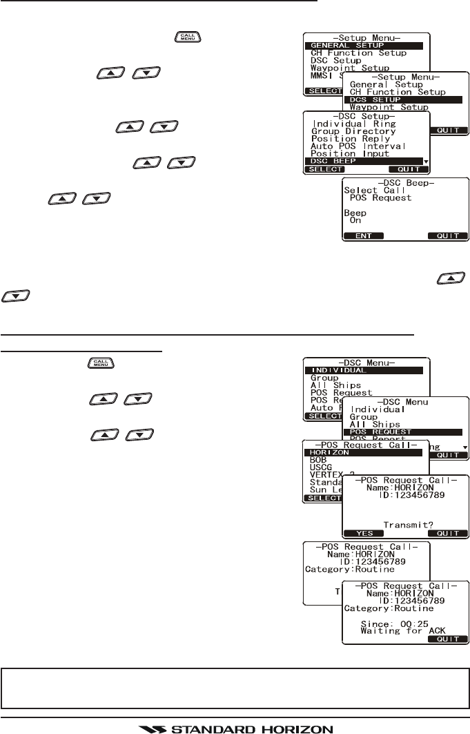
12.8.2 Setting up a Position Request Ringer
The GX1600 has the capability to turn off the Position Request ringer.
1. Press and hold down the key until “SetupSetup
SetupSetup
Setup
MenuMenu
MenuMenu
Menu” appears.
2. Press the / key to select “DSCDSC
DSCDSC
DSC
SETUPSETUP
SETUPSETUP
SETUP” menu.
3. Press the [SELECT] soft key, then select “DSCDSC
DSCDSC
DSC
BEEPBEEP
BEEPBEEP
BEEP” with the / key.
4. Press the [SELECT] soft key, then select “POSPOS
POSPOS
POS
RequestRequest
RequestRequest
Request” with the / key.
5. Press the [ENT] soft key, then select “OffOff
OffOff
Off” with
the / key.
6. Press the [ENT] soft key to store the selected set-
ting.
7. Press the [QUIT] soft key several times to return to radio operation.
To re-enable the ringer tone, repeat the above procedure, pressing the /
key to select “OnOn
OnOn
On” in step “5” above.
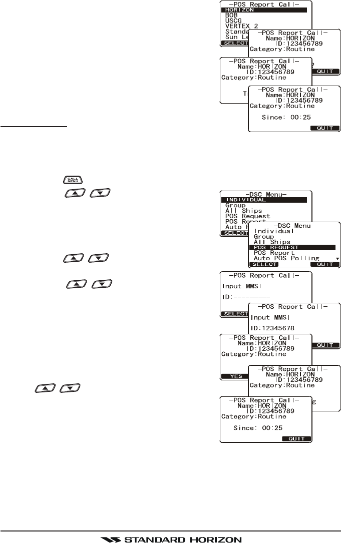
12.8.3 Transmitting a Position Request to Another Vessel
Pre-Programmed Request
1. Press the key. The “DSC MenuDSC Menu
DSC MenuDSC Menu
DSC Menu” will ap-
pear.
2. Press the / key to select “POS RE-POS RE-
POS RE-POS RE-
POS RE-
QUESTQUEST
QUESTQUEST
QUEST”.
3. Press the / key to select a name
that was stored in the Individual DSC direc-
tory, then press the [SELECT] soft key.
4. Press the [YES] soft key to transmit the Posi-
tion Request DSC call.
5. When the GX1600 receives the position from the
polled vessel it is shown on the radio display
and also transferred to a GPS Chart plotter
with NMEA DSC and DSE sentences.
6. Press the [QUIT] soft key to return to radio
operation.
NOTE
If the GX1600 does not receive a position data from the polled vessel,
the display will show “NO POSITION DATA.”
FCC ID:K6630483X3D / IC:511B-30483X3S
Vertex Standard Co., Ltd.
GX1600Page 60
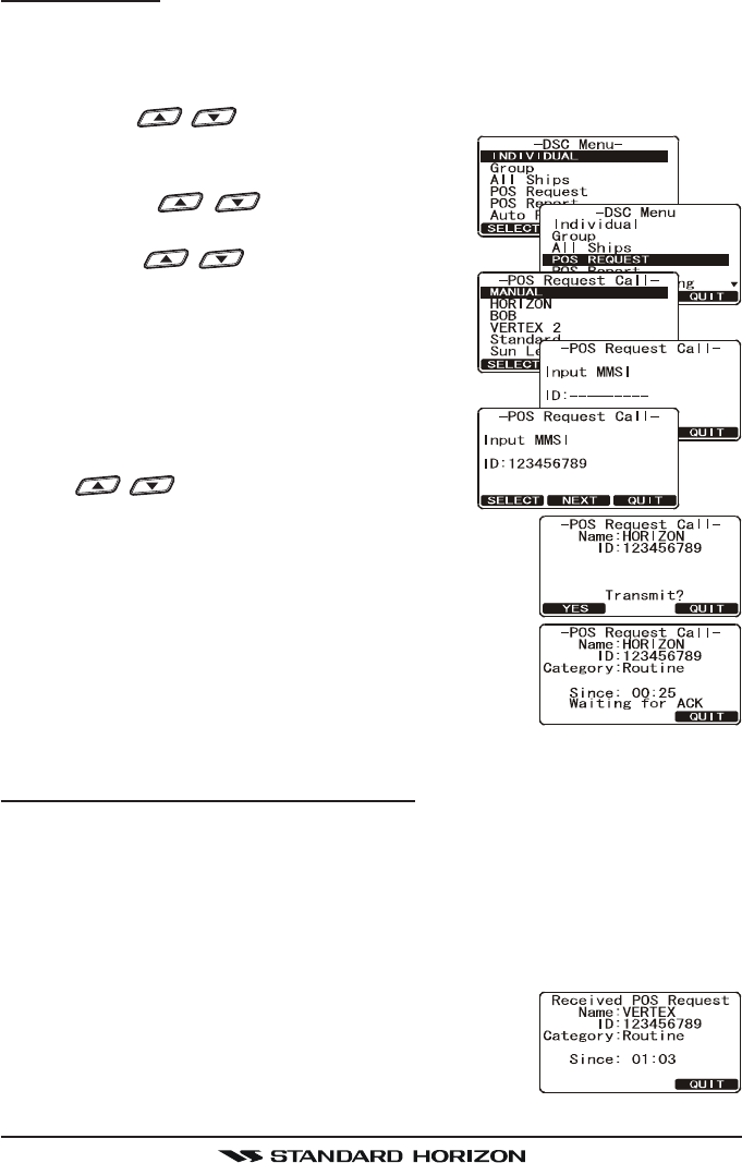
Manual Request
This feature allows you to request the position of vessel by manually entering
the MMSI of the ship you want to send your position to.
1. Press the [CALL(MENU)] key. The “DSC MenuDSC Menu
DSC MenuDSC Menu
DSC Menu” will appear.
2. Press the / key to select “POS REQUESTPOS REQUEST
POS REQUESTPOS REQUEST
POS REQUEST”.
3. Press the [SELECT] soft key to show the “Last
Individual Call”.
4. Press the / key to select the
“MANUALMANUAL
MANUALMANUAL
MANUAL,” then press the [SELECT] soft key.
5. Press the / key to select the first
number of the MMSI (nine digits) which you
want to contact, then press the [SELECT] soft
key to step to the next number.
6. Repeat step 5 to set the MMSI number.
7. If a mistake was made entering in the MMSI
number, repeat pressing the [BACK] soft key
until the wrong number is selected, then press
the / key to correct the entry.
8. When finished entering the MMSI number,
press and hold the [SELECT] soft key.
9. Press the [YES] soft key to transmit the position re-
quest DSC call.
10. When the GX1600 receives the position from the
polled vessel it is shown on the radio display and
also transferred to the GPS Chart plotter with NMEA
DSC and DSE sentences.
11. Press the [QUIT] soft key to return to radio operation.
12.8.4 Receiving a Position Request
When a position request call is received from another vessel, a ringing alarm
sounds and POS REQUEST will be shown in the display. Operation and trans-
ceiver function differs depending on “Position ReplyPosition Reply
Position ReplyPosition Reply
Position Reply” in the “DSC SetupDSC Setup
DSC SetupDSC Setup
DSC Setup” menu
setting discussed below:
Automatically reply:
1. When a position request call is received, a calling alarm sounds 4 times.
Then requested position coordinates are transmit-
ted automatically to the vessel requesting your ves-
sels position.
2. To exit from position request display, press
the [QUIT] soft key.
FCC ID:K6630483X3D / IC:511B-30483X3S
Vertex Standard Co., Ltd.
Page 61GX1600
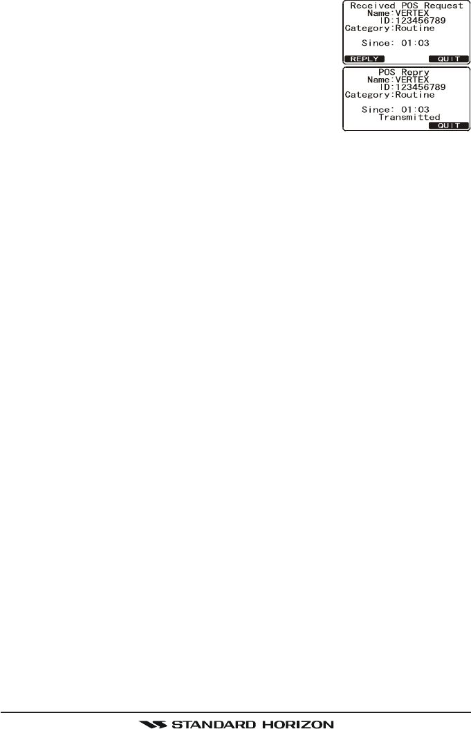
Manually reply:
1. When a position request call is received from an-
other vessel, the display will be as shown in the il-
lustration at the right.
2. A ringing alarm sounds 4 times. To send your ves-
sels position to the requesting vessel, press the [RE-
PLY] soft key. Or to exit from position request dis-
play, press the [QUIT] soft key.
FCC ID:K6630483X3D / IC:511B-30483X3S
Vertex Standard Co., Ltd.
GX1600Page 62
12.9 POSITION REPORT
The feature is similar to Position Request, however instead of requesting a
position of another vessel this function allows you to send your position to
another vessel. Your vessel must have an operating GPS receiver connected
for the GX1600 to send the position.
NOTE
To transmit a Position Report Call, a GPS must be connected to the
radio and the GX1600 Individual directory must be programmed with
stations you wish to send your position to. To setup this directory refer to
section “11.5.1 Setting up the Individual / Position Call Directory.”
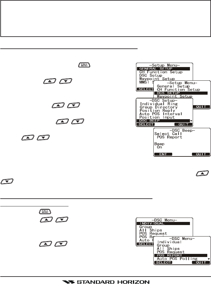
12.9.1 Setting up a Position Report Ringer
The GX2000/GX2100 has the capability to turn off the Position Report ringer.
1. Press and hold down the key until “SetupSetup
SetupSetup
Setup
MenuMenu
MenuMenu
Menu” appears.
2. Press the / key to select “DSCDSC
DSCDSC
DSC
SETUPSETUP
SETUPSETUP
SETUP” menu.
3. Press the [SELECT] soft key, then select “DSCDSC
DSCDSC
DSC
BEEPBEEP
BEEPBEEP
BEEP” with the / key.
4. Press the [SELECT] soft key, then select “POSPOS
POSPOS
POS
ReportReport
ReportReport
Report” with the / key.
5. Press the [ENT] soft key, then select “OffOff
OffOff
Off” with
the / key.
6. Press the [ENT] soft key to store the selected set-
ting.
7. Press the [QUIT] soft key several times to return to radio operation.
To re-enable the ringer tone, repeat the above procedure, pressing the /
key to select “OnOn
OnOn
On” in step “5” above.
12.9.2 Transmitting a DSC Position Report Call
Pre-Programmed Calling
1. Press the key. The “DSC MenuDSC Menu
DSC MenuDSC Menu
DSC Menu” will appear.
2. Press the / key to select “POS RE-POS RE-
POS RE-POS RE-
POS RE-
PORTPORT
PORTPORT
PORT”. (To cancel, press the [QUIT] soft key.)
3. Press the [SELECT] soft key.
4. Press the / key to select the name
in the directory, then press the [SELECT] soft key.
5. Press the [YES] soft key to send your position to the
selected vessel.
FCC ID:K6630483X3D / IC:511B-30483X3S
Vertex Standard Co., Ltd.
Page 63GX1600
6. Press the [QUIT] key to return to radio opera-
tion.
Manual Calling
This feature allows you to send your position to another
vessel by manually entering the MMSI of the ship you want to send your posi-
tion to.
1. Press the key. The “DSC MenuDSC Menu
DSC MenuDSC Menu
DSC Menu” will appear.
2. Press the / key to select “POS RE-POS RE-
POS RE-POS RE-
POS RE-
PORTPORT
PORTPORT
PORT”. (To cancel, press the [QUIT] soft key.)
3. Press the [SELECT] soft key. The transceiver
will beep, and the “Position Report Call” menu
will appear.
4. Press the / key to select “MANUALMANUAL
MANUALMANUAL
MANUAL”, then
press the [SELECT] soft key.
5. Press the / key to select the first
number of the MMSI which you want to con-
tact, then press the [SELECT] soft key to step
to the next number.
6. Repeat step 5 to set the MMSI number.
7. If a mistake was made entering in the MMSI
number, repeat pressing the [BACK] soft key
until the wrong number is selected, then press
the / key to correct the entry.
8. When finished entering the MMSI number,
press and hold the Press the [SELECT] soft
key.
9. Press the [YES] soft key to send your posi-
tion to the selected vessel.
10. Press the [QUIT] soft key to return to radio operation.
FCC ID:K6630483X3D / IC:511B-30483X3S
Vertex Standard Co., Ltd.
GX1600Page 64
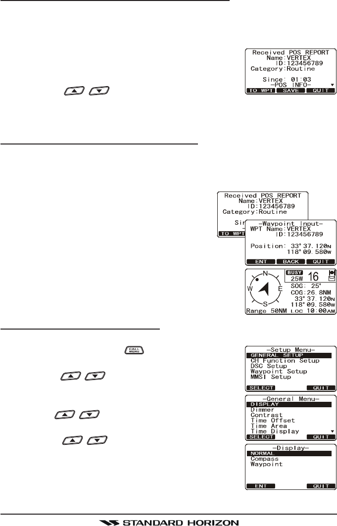
12.9.3 Receiving a DSC Position Report Call
When another vessel transmits their vessels location to the GX1600 the fol-
lowing will happen:
1. A ringing sound will be produced when the call is received and NMEA
sentences DSC, DSE are outputted so the position
can be shown on a chart plotter or a computer.
2. Press the any key to stop ringing.
3. Press the / key to see position informa-
tion of the station.
4. To exit to radio mode, press the [QUIT] soft key.
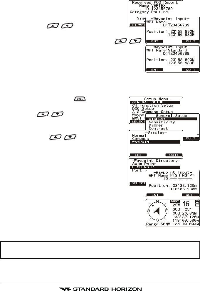
12.9.4 Navigating to a Position Report
The GX1600 has a feature that allows navigation to a received Position Report
call by using the Compass display. Navigating to the position of a Position
Report call may be enabled by the procedure below.
1. After the Position Report call has been re-
ceived: press the [TO WPT] soft key.
2. To start navigating using the compass display,
press and hold the [ENT] soft key until the
Compass Page is shown. The display indicates the
distance and direction of the received vessel, and
also the compass indicates the received vessel by
dot ().
Stop Navigating to a Position Report
To stop navigation and return to the radio mode:
1. Press and hold down the key until “Setup MenuSetup Menu
Setup MenuSetup Menu
Setup Menu”
appears.
2. Press the / key to select “GENERAL SETUPGENERAL SETUP
GENERAL SETUPGENERAL SETUP
GENERAL SETUP”
menu.
3. Press the [SELECT] soft key, then select “DISPLAYDISPLAY
DISPLAYDISPLAY
DISPLAY”
with the / key.
4. Press the [SELECT] soft key.
5. Press the / key to select “NORMALNORMAL
NORMALNORMAL
NORMAL”.
6. Press the [ENT] soft key to return to radio opera-
tion.
FCC ID:K6630483X3D / IC:511B-30483X3S
Vertex Standard Co., Ltd.
Page 65GX1600
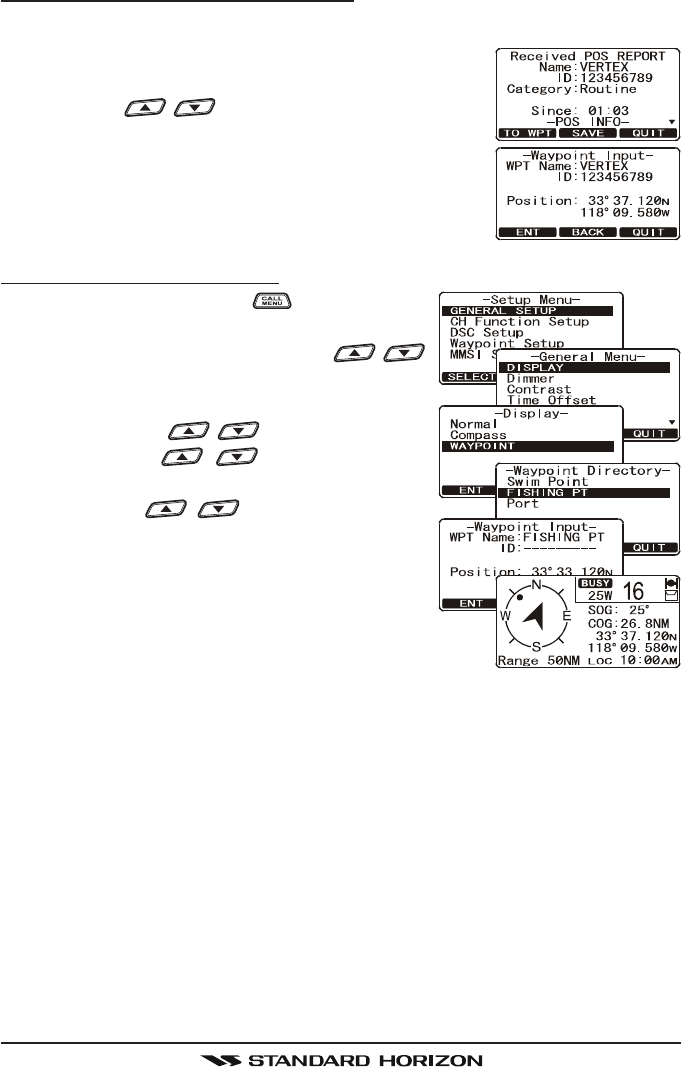
Saving a Position Report as a Waypoint
The GX1600 can save a Position Report call in the radios memory as a waypoint.
1. After the Position Report call has been received:
Press the [SAVE] soft key.
2. Press the / key to change the first letter in
the name of the waypoint and press the [ENT] soft
key.
3. Repeat step 2 until the WPT Name is entered.
4. Press and hold the [ENT] soft key to save the
waypoint into memory.
Navigating to a saved waypoint
1. Press and hold down the key until “SetupSetup
SetupSetup
Setup
MenuMenu
MenuMenu
Menu” appears.
2. Select “GENERAL SETUPGENERAL SETUP
GENERAL SETUPGENERAL SETUP
GENERAL SETUP” with the /
key.
3. Press the [SELECT] soft key, then select “DIS-DIS-
DIS-DIS-
DIS-
PLAYPLAY
PLAYPLAY
PLAY” with the / key.
4. Press the / key to select
“WAYPOINTWAYPOINT
WAYPOINTWAYPOINT
WAYPOINT” and press the [ENT] soft key.
5. Press the / key to select the
waypoint name and press the [ENT] soft key.
6. Press the [ENT] key so show the compass
display and to navigate to the waypoint. The
display indicates the distance and direction
of the saved waypoint, and also the compass indi-
cates the saved waypoint by dot ().
FCC ID:K6630483X3D / IC:511B-30483X3S
Vertex Standard Co., Ltd.
GX1600Page 66
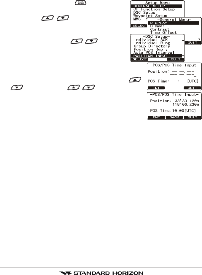
12.10 MANUAL INPUTTING OF THE GPS LOCATION (LAT/LON)
You may send the Latitude/Longitude of your vessel manually even if the
GX1600 is not connected the GPS receiver unit.
After the position is entered, transmitting a DSC Distress, Position Request, or
Position Report will contain the manually entered position.
1. Press and hold down the key until “SetupSetup
SetupSetup
Setup
MenuMenu
MenuMenu
Menu” appears.
2. Press the / key to select “DSCDSC
DSCDSC
DSC
SETUPSETUP
SETUPSETUP
SETUP” menu.
3. Press the [SELECT] soft key, then select “PO-PO-
PO-PO-
PO-
SITION INPUTSITION INPUT
SITION INPUTSITION INPUT
SITION INPUT” with the / key.
4. Press the [SELECT] soft key. The transceiver
will beep, and the display will be as shown in
the illustration on the right.
5. Enter the latitude/longitude of your vessel and your
local UTC time in the 24-hour notation by the /
key. Press the / key to select the
number and press the [ENT] soft key to move the
cursor to the next character. You may backspace
the cursor by pressing the [BACK] soft key, if you
make a mistake.
6. To store the data entered, press and hold the [ENT] soft key.
7. Press the [QUIT] soft key several times to return to radio operation.
FCC ID:K6630483X3D / IC:511B-30483X3S
Vertex Standard Co., Ltd.
Page 67GX1600
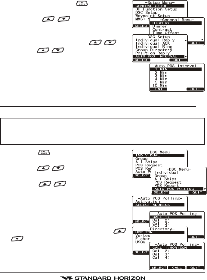
12.11 AUTO DSC POLLING
The GX1600 has the capability to automatically track four stations programmed
into the Indvidual directory.
The following procedure allows the time interval between position requests to
be setup.
1. Press and hold down the key until “SetupSetup
SetupSetup
Setup
MenuMenu
MenuMenu
Menu” appears.
2. Press the / key to select “DSCDSC
DSCDSC
DSC
SETUPSETUP
SETUPSETUP
SETUP” menu.
3. Press the [SELECT] soft key, then select
“AUTO DSC INTERVALAUTO DSC INTERVAL
AUTO DSC INTERVALAUTO DSC INTERVAL
AUTO DSC INTERVAL” with the / key.
4. Press the / key to select the desired
interval time (1,2,3,4,5,10,30 and 40 minutes)
and press the [ENT] soft key.
5. Press the [QUIT] soft key numerous times to exit to
the radio mode.
12.11.1 Selecting Stations to be Automatically Polled (tracked)
NOTE
The radio uses the Individual directory to select stations. Refer to sec-
tion “11.5.1 Setting up the Individual / Position Call Directory” and to
enter MMSI of stations you want to poll before proceeding.
1. Press the key. The “DSC MenuDSC Menu
DSC MenuDSC Menu
DSC Menu” will ap-
pear.
2. Press the / key to select “AUTO POSAUTO POS
AUTO POSAUTO POS
AUTO POS
POLLINGPOLLING
POLLINGPOLLING
POLLING”, then press the [SELECT] soft key.
3. Press the / key to select the “SELECT AD-SELECT AD-
SELECT AD-SELECT AD-
SELECT AD-
DRESSDRESS
DRESSDRESS
DRESS”, then press the [SELECT] soft key.
4. The radio will show 4 calling stations to be
selected, select “CALL 1CALL 1
CALL 1CALL 1
CALL 1” and press the [SE-
LECT] soft key.
5. The radio will show the stations programmed
in the Individual directory. Press the /
key to select the desired station and
press the [SELECT] soft key.
6. Repeat steps 4 and 5 for CALL 2, CALL 3
and CALL 4 entries.
FCC ID:K6630483X3D / IC:511B-30483X3S
Vertex Standard Co., Ltd.
GX1600Page 68
7. When finished, press the [QUIT] soft key numerous times to exit to the
radio mode.
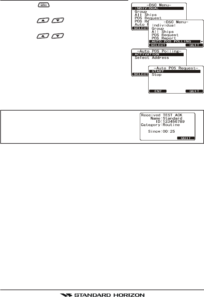
12.11.2 Enable/Disable Auto DSC Polling
1. Press the key. The “DSC MenuDSC Menu
DSC MenuDSC Menu
DSC Menu” will ap-
pear.
2. Press the / key to select “AUTO POSAUTO POS
AUTO POSAUTO POS
AUTO POS
POLLINGPOLLING
POLLINGPOLLING
POLLING”, then press the [SELECT] soft key.
3. Press the / key to select the “ACTIVATIONACTIVATION
ACTIVATIONACTIVATION
ACTIVATION”,
then press the [SELECT] soft key.
4. Select “STARTSTART
STARTSTART
START” to enable transmissions to the
stations or “STOPSTOP
STOPSTOP
STOP” to disable transmissions to
stations.
5. Press the [ENT] soft key.
6. Press the [QUIT] soft key numerous times to exit to
the radio mode.
NOTE
When the radio receives position reports from a
called vessel the display will show the image to
the right and also output NMEA 0183 DSC and
DSE sentences to a GPS Chart plotter.
FCC ID:K6630483X3D / IC:511B-30483X3S
Vertex Standard Co., Ltd.
Page 69GX1600
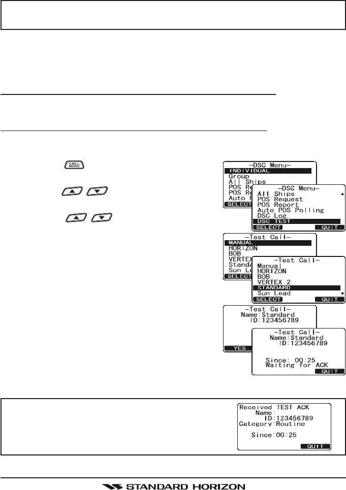
12.12 DSC TEST
This function is used to contact another DSC equipped vessel to ensure the
DSC functions of the radio are operating.
NOTE
To use this feature, the radio you will be transmitting the test call to
needs to have the DSC Test feature.
To perform the DSC test you will need to enter a MMSI of another vessel into
the Individual directory or manually enter in the MMSI using the procedure
below.
12.12.1 Programming MMSI into Individual Directory
Refer to section “11.5.1 Setting up the Individual / Position Call Directory”.
12.12.2 DSC Test call by using Individual Directory
1. After programming a individual MMSI into the GX1600 (refer to section
“11.5.1 Setting up the Individual / Position Call Directory”).
2. Press the key. The “DSC MenuDSC Menu
DSC MenuDSC Menu
DSC Menu” will ap-
pear.
3. Press the / key to select “DSC TESTDSC TEST
DSC TESTDSC TEST
DSC TEST”,
then press the [SELECT] soft key.
4. Press the / key to select the Ship name
and press the [SELECT] soft key.
5. Press the [YES] soft key to transmit the DSC
test call to the other vessel.
NOTE
After the radio receive a Test Call reply from ves-
sel that was called, the radio will ring and show
TEST ACK display, which confirms the radio you
called received the test call.
FCC ID:K6630483X3D / IC:511B-30483X3S
Vertex Standard Co., Ltd.
GX1600Page 70
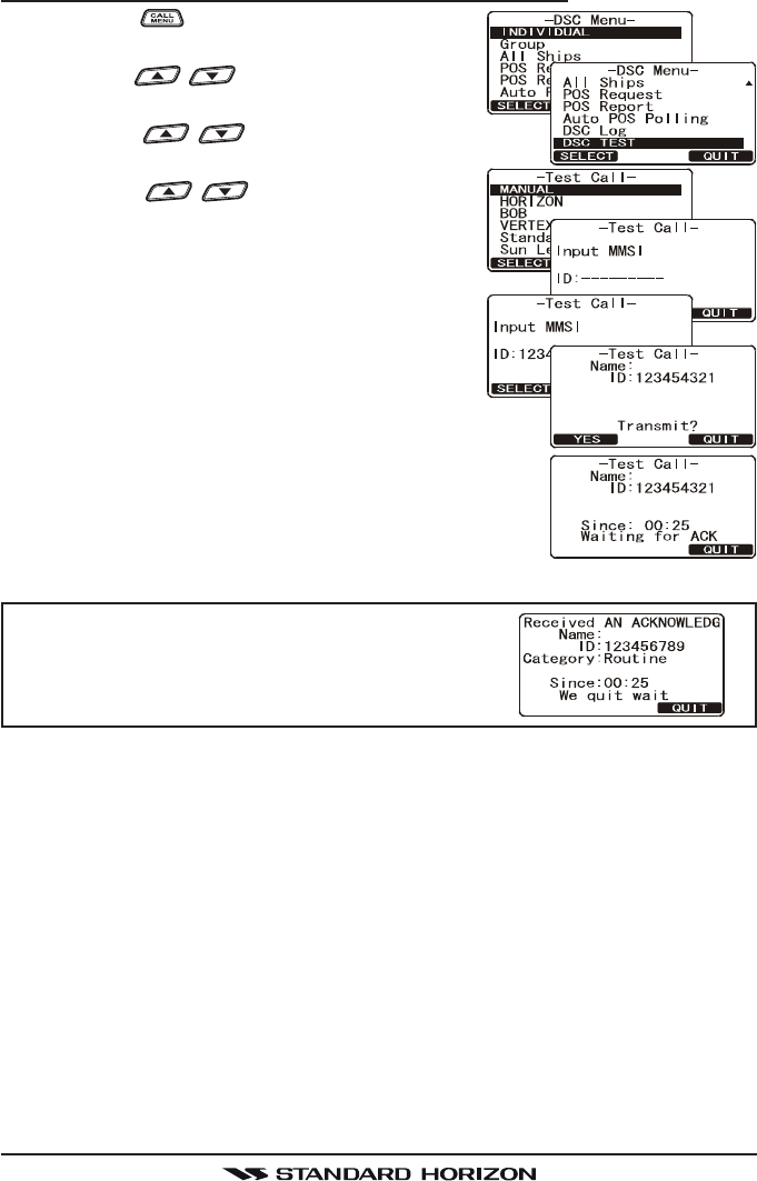
12.12.3 DSC Test Call by Manually Entering MMSI
1. Press the key. The “DSC MenuDSC Menu
DSC MenuDSC Menu
DSC Menu” will ap-
pear.
2. Press the / key to select “DSC TESTDSC TEST
DSC TESTDSC TEST
DSC TEST”,
then press the [SELECT] soft key.
3. Press the / key to select “MANUALMANUAL
MANUALMANUAL
MANUAL” and
press the [SELECT] soft key.
4. Press the / key to select the first
digit in the MMSI and press the [SELECT] soft
key.
5. Repeat step 4 until all the numbers of the
MMSI are shown on the display.
6. Press and hold the [SELECT] soft key to show
the Test Call page.
7. Press the [YES] soft key to transmit the DSC
Test Call to the other vessel.
NOTE
After the radio receive a Test Call reply from ves-
sel that was called, the radio will ring and show
TEST ACK display, which confirms the radio you
called received the test call.
FCC ID:K6630483X3D / IC:511B-30483X3S
Vertex Standard Co., Ltd.

Page 71GX1600
MEMO
FCC ID:K6630483X3D / IC:511B-30483X3S
Vertex Standard Co., Ltd.
GX1600Page 72
13 GENERAL SETUP
The optional CMP30 (RAM3) Remote Station Microphone can also
change the SETUP menu using the following procedure.
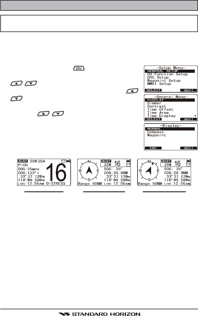
13.1 DISPLAY
The GX1600 can select additional screens other than the default normal (Ra-
dio) display by using the procedure below.
1. Press and hold down the key until “Setup MenuSetup Menu
Setup MenuSetup Menu
Setup Menu”
appears, then select “GENERAL SETUPGENERAL SETUP
GENERAL SETUPGENERAL SETUP
GENERAL SETUP” with the
/ key.
2. Press the [SELECT] soft key, then press the /
key to select “DISPLAYDISPLAY
DISPLAYDISPLAY
DISPLAY”.
3. Press the [SELECT] soft key.
4. Press the / key to select desired screen
type “NORMALNORMAL
NORMALNORMAL
NORMAL”, “COMPASSCOMPASS
COMPASSCOMPASS
COMPASS”, or “WAYPOINTWAYPOINT
WAYPOINTWAYPOINT
WAYPOINT”.
5. Press the [SELECT] soft key to store the selected
setting.
6. Press the [QUIT] soft key several times to return to
radio operation.
“NORMAL” DISPLAY “COMPASS” DISPLAY “WAYPOINT” DISPLAY
FCC ID:K6630483X3D / IC:511B-30483X3S
Vertex Standard Co., Ltd.
Page 73GX1600
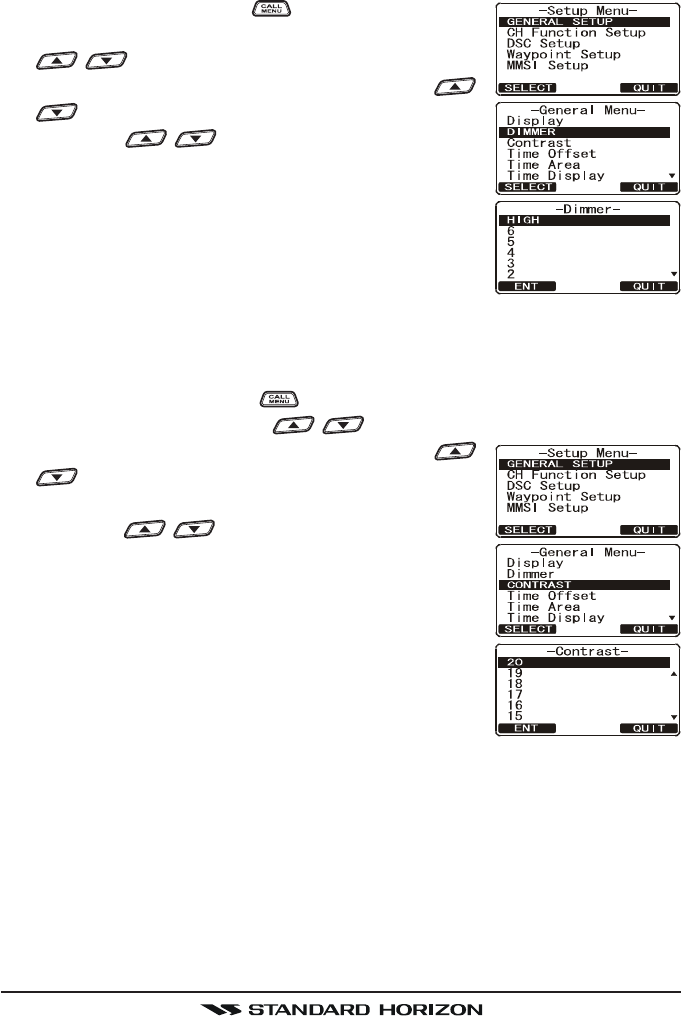
13.2 LAMP ADJUSTING
This menu selection adjusts the backlight intensity.
1. Press and hold down the key until “Setup MenuSetup Menu
Setup MenuSetup Menu
Setup Menu”
appears, then select “GENERAL SETUPGENERAL SETUP
GENERAL SETUPGENERAL SETUP
GENERAL SETUP” with the
/ key.
2. Press the [SELECT] soft key, then press the /
key to select “DIMMERDIMMER
DIMMERDIMMER
DIMMER”.
4. Press the / key to select the desired level
(“HIGHHIGH
HIGHHIGH
HIGH” is default). When “OFFOFF
OFFOFF
OFF” is selected, the lamp
is turned off.
5. Press the [ENT] soft key to store the selected level.
6. Press the [QUIT] soft key several times to return to
radio operation.
13.3 DISPLAY CONTRAST
Due to varying this selection sets up the display contrast for overhead or dash
installations.
1. Press and hold down the key until “Setup MenuSetup Menu
Setup MenuSetup Menu
Setup Menu” appears, then select
“GENERAL SETUPGENERAL SETUP
GENERAL SETUPGENERAL SETUP
GENERAL SETUP” with the / key.
2. Press the [SELECT] soft key, then press the /
key to select “CONTRASTCONTRAST
CONTRASTCONTRAST
CONTRAST”.
3. Press the [SELECT] soft key.
4. Press the / key to select the desired level.
The contrast level can be set from “00
00
0” to “3131
3131
31” (“HIGHHIGH
HIGHHIGH
HIGH”
is default).
5. Press the [ENT] soft key to store the selected level.
6. Press the [QUIT] soft key several times to return to
radio operation.
FCC ID:K6630483X3D / IC:511B-30483X3S
Vertex Standard Co., Ltd.
GX1600Page 74
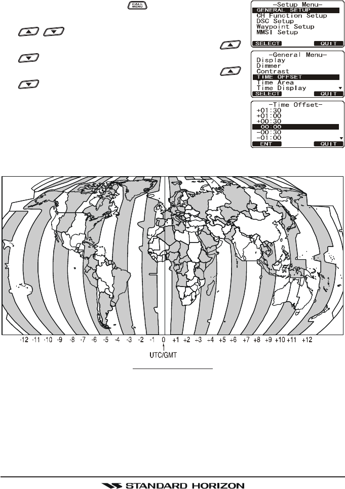
OFFSET TIME TABLE
13.4 TIME OFFSET
Sets the time offset between local time (with inputted offset) and UTC (without
time offset) shown on the display. Time is displayed only when an optional
GPS Chart Plotter is connected.
1. Press and hold down the key until “Setup MenuSetup Menu
Setup MenuSetup Menu
Setup Menu”
appears, then select “GENERAL SETUPGENERAL SETUP
GENERAL SETUPGENERAL SETUP
GENERAL SETUP” with the
/ key.
2. Press the [SELECT] soft key, then press the /
key to select “TIME OFFSETTIME OFFSET
TIME OFFSETTIME OFFSET
TIME OFFSET”.
3. Press the [SELECT] soft key, then press the /
key to select time offset of your location. See
illustration below to find your offset time. If “00:0000:00
00:0000:00
00:00”
is assigned, the time is the same as UTC (Universal
Time Coordinated or GPS Satellite Time).
4. Press the [ENT] soft key to store the time offset.
5. Press the [QUIT] soft key several times to return to
radio operation.
FCC ID:K6630483X3D / IC:511B-30483X3S
Vertex Standard Co., Ltd.
Page 75GX1600
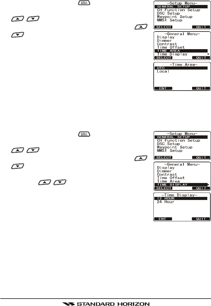
13.5 TIME AREA
This menu selection allows the radio to show UTC time or local time with the
offset.
1. Press and hold down the key until “Setup MenuSetup Menu
Setup MenuSetup Menu
Setup Menu”
appears, then select “GENERAL SETUPGENERAL SETUP
GENERAL SETUPGENERAL SETUP
GENERAL SETUP” with the
/ key.
2. Press the [SELECT] soft key, then press the /
key to “TIME AREATIME AREA
TIME AREATIME AREA
TIME AREA”.
3. Press the [SELECT] soft key.
4. Rotate the CHANNEL knob to select “UTCUTC
UTCUTC
UTC” or “LO-LO-
LO-LO-
LO-
CALCAL
CALCAL
CAL”.
5. Press the [ENT] soft key to store the selected set-
ting.
6. Press the [QUIT] soft key several times to return to
radio operation.
13.6 TIME DISPLAY
This menu selection allows the radio to show time in 12-hour or 24-hour for-
mat.
1. Press and hold down the key until “Setup MenuSetup Menu
Setup MenuSetup Menu
Setup Menu”
appears, then select “GENERAL SETUPGENERAL SETUP
GENERAL SETUPGENERAL SETUP
GENERAL SETUP” with the
/ key.
2. Press the [SELECT] soft key, then press the /
key to select “TIME DISPLAYTIME DISPLAY
TIME DISPLAYTIME DISPLAY
TIME DISPLAY”.
3. Press the [SELECT] soft key.
4. Press the / key to select “12 HOUR12 HOUR
12 HOUR12 HOUR
12 HOUR” or “2424
2424
24
HOURHOUR
HOURHOUR
HOUR”.
5. Press the [ENT] soft key to store the selected set-
ting.
6. Press the [QUIT] soft key several times to return to
radio operation.
FCC ID:K6630483X3D / IC:511B-30483X3S
Vertex Standard Co., Ltd.
GX1600Page 76
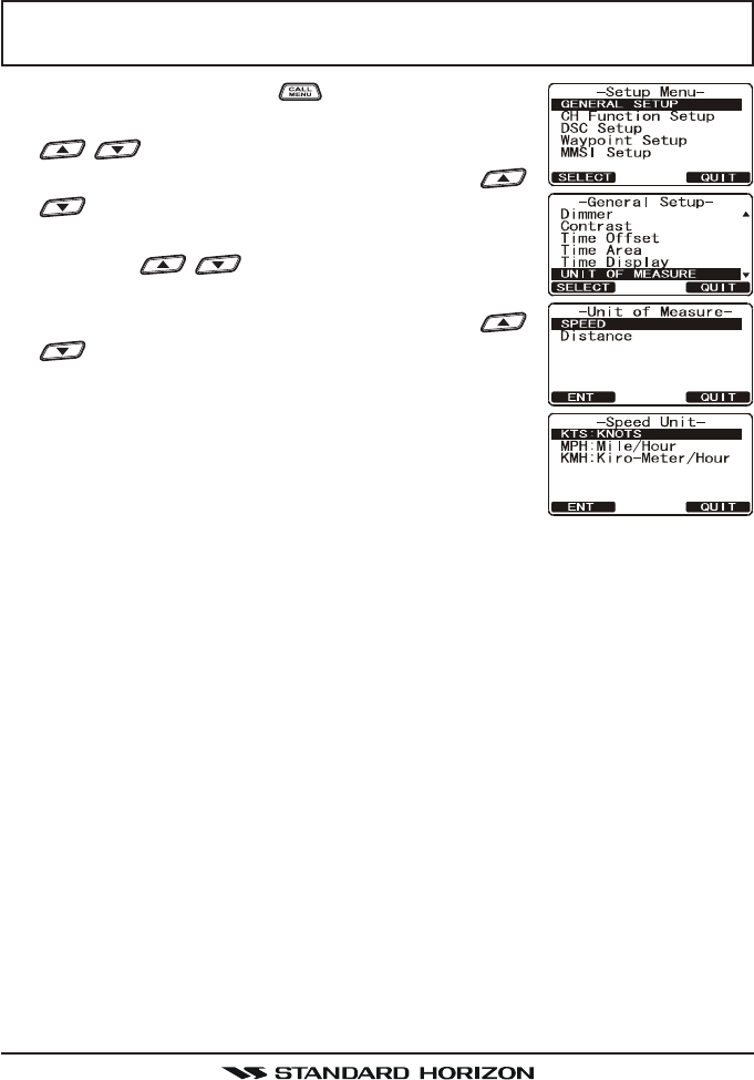
13.7 UNIT OF MEASURE
Allows Navigation and AIS displays to be shown in “Knot”, “Mile/Hour” or “Kilo-
Meter/Hour” (for speed) and “Nautical Mile” or “Kilo-Meter” (for distance).
NOTE
A GPS must be connected to the radio to be able to show SPEED and
DISTANCE.
1. Press and hold down the key until “Setup MenuSetup Menu
Setup MenuSetup Menu
Setup Menu”
appears, then select “GENERAL SETUPGENERAL SETUP
GENERAL SETUPGENERAL SETUP
GENERAL SETUP” with the
/ key.
2. Press the [SELECT] soft key, then press the /
key to select “UNIT OF MEASUREUNIT OF MEASURE
UNIT OF MEASUREUNIT OF MEASURE
UNIT OF MEASURE”.
3. Press the [SELECT] soft key.
4. Press the / key to select “SPEEDSPEED
SPEEDSPEED
SPEED” or “DIS-DIS-
DIS-DIS-
DIS-
TANCETANCE
TANCETANCE
TANCE” which you wish to change.
5. Press the [SELECT] soft key, then press the /
key to select desired unit. Available selections
are KTS (knot), MPH (Mile/Hour), or KMH (Kilo-
Meter/Hour) for speed, and NH (Nautical Mile) or
KM (Kilo-Meter) for distance.
6. Press the [ENT] soft key to store the selected set-
ting.
7. Press the [QUIT] soft key several times to return to
radio operation.
FCC ID:K6630483X3D / IC:511B-30483X3S
Vertex Standard Co., Ltd.
Page 77GX1600
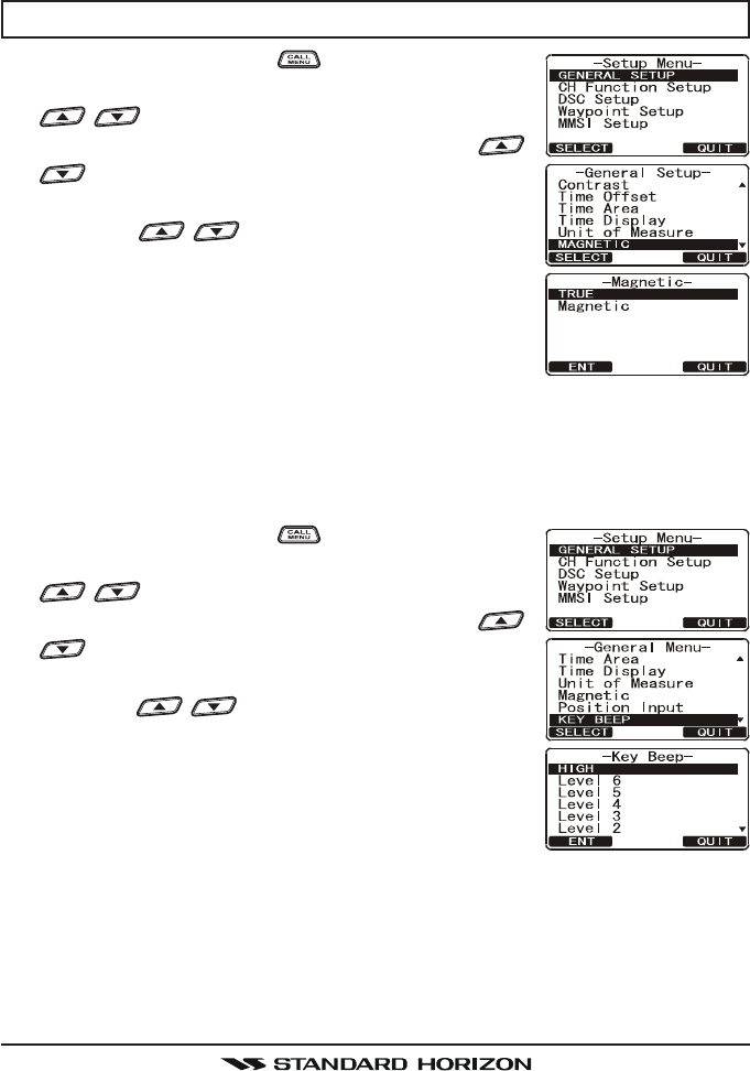
13.8 MAGNETIC
This selection allows customizing the GPS COG (Course Over Ground) dis-
played in True or Magnetic.
NOTE
A GPS must be connected to the radio to be able to show COG.
1. Press and hold down the key until “Setup MenuSetup Menu
Setup MenuSetup Menu
Setup Menu”
appears, then select “GENERAL SETUPGENERAL SETUP
GENERAL SETUPGENERAL SETUP
GENERAL SETUP” with the
/ key.
2. Press the [SELECT] soft key, then press the /
key to select “MAGNETICMAGNETIC
MAGNETICMAGNETIC
MAGNETIC”.
3. Press the [SELECT] soft key.
4. Press the / key to select “TRUETRUE
TRUETRUE
TRUE” or “MAG-MAG-
MAG-MAG-
MAG-
NETICNETIC
NETICNETIC
NETIC”.
5. Press the [ENT] soft key to store the selected set-
ting.
6. Press the [QUIT] soft key several times to return to
radio operation.
13.9 KEY BEEP
This selection is used to select the beep tone volume level when a key is
pressed.
1. Press and hold down the key until “Setup MenuSetup Menu
Setup MenuSetup Menu
Setup Menu”
appears, then select “GENERAL SETUPGENERAL SETUP
GENERAL SETUPGENERAL SETUP
GENERAL SETUP” with the
/ key.
2. Press the [SELECT] soft key, then press the /
key to select “KEY BEEPKEY BEEP
KEY BEEPKEY BEEP
KEY BEEP”.
3. Press the [SELECT] soft key.
4. Press the / key to select the desired level.
The beep level can be set from “LEVEL 1LEVEL 1
LEVEL 1LEVEL 1
LEVEL 1” to “LEVELLEVEL
LEVELLEVEL
LEVEL
66
66
6”, “HIGHHIGH
HIGHHIGH
HIGH”, or “OFFOFF
OFFOFF
OFF”.
5. Press the [ENT] soft key to store the selected level.
6. Press the [QUIT] soft several times to return to ra-
dio operation.
FCC ID:K6630483X3D / IC:511B-30483X3S
Vertex Standard Co., Ltd.
GX1600Page 78
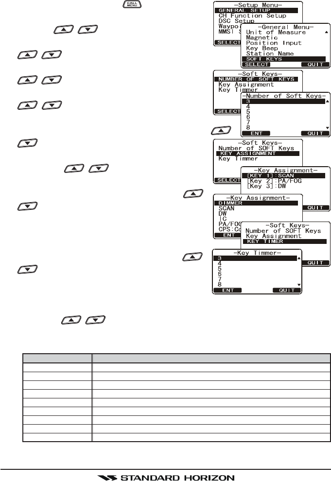
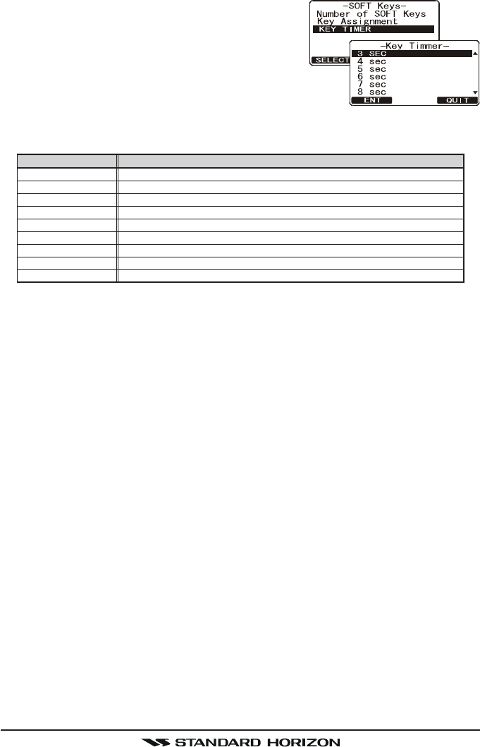
13.10 SOFT KEYS
This menu item allows selection of the number of soft keys, soft key selection
and how long the display will show the soft key icon after a soft key is pressed.
1. Press and hold down the key until “SetupSetup
SetupSetup
Setup
MenuMenu
MenuMenu
Menu” appears, then select “GENERAL SETUPGENERAL SETUP
GENERAL SETUPGENERAL SETUP
GENERAL SETUP”
with the / key.
2. Press the [SELECT] soft key, then press the
/ key to “SOFT KEYSOFT KEY
SOFT KEYSOFT KEY
SOFT KEY”.
3. Press the [SELECT] soft key, then press the
/ key to “NUMBER OF SOFT KEYSNUMBER OF SOFT KEYS
NUMBER OF SOFT KEYSNUMBER OF SOFT KEYS
NUMBER OF SOFT KEYS”.
4. Press the [SELECT] soft key, then press the
/ key to select the number of soft
keys (33
33
3 through 1010
1010
10).
5. Press the [SELECT] soft key, then press the /
key to select “KEY ASSIGNMENTKEY ASSIGNMENT
KEY ASSIGNMENTKEY ASSIGNMENT
KEY ASSIGNMENT” (to
change the use of selected soft keys).
6. Press the / key to select the key
(“KEY1KEY1
KEY1KEY1
KEY1”, “KEY2KEY2
KEY2KEY2
KEY2”, or “KEY3KEY3
KEY3KEY3
KEY3”), and press the
[SELECT] soft key. Then, press the /
key to select the new function to be as-
signed, and press the [SELECT] soft key.
Available functions are listed below. Repeat
step 6 to program the other soft keys.
7. Press the [QUIT] key, then press the /
key to select “KEY TIMERKEY TIMER
KEY TIMERKEY TIMER
KEY TIMER” (selects how
long the soft key icon will be shown on the
display after a soft key is pressed, default is
5 seconds). Then, press the [SELECT] soft key.
8. Press the / key to select the time.
9. Press the [ENT] soft key to store the selected setting.
10. Press the [QUIT] soft key several times to return to radio operation.
DISPLAY
SCAN
DW
IC
CMP: COMPASS
WPT
PRESET
WX
MARK
PRESET 0 - 9
FUNCTION
Starts and stops Scanning.
Starts and stops Dual Watch Scan.
Activates Intercom between radio and RAM3 mic (optional RAM3 required).
Shows to the “Compass” display.
Shows to the “Waypoint” Navigation display.
Porgrams or deletes the preset memory channel.
Immediately recalls the last select the weather channel.
Marks the current position for the “Waypoint”.
Immediately recalls the preset memory channel.
FCC ID:K6630483X3D / IC:511B-30483X3S
Vertex Standard Co., Ltd.
Page 79GX1600
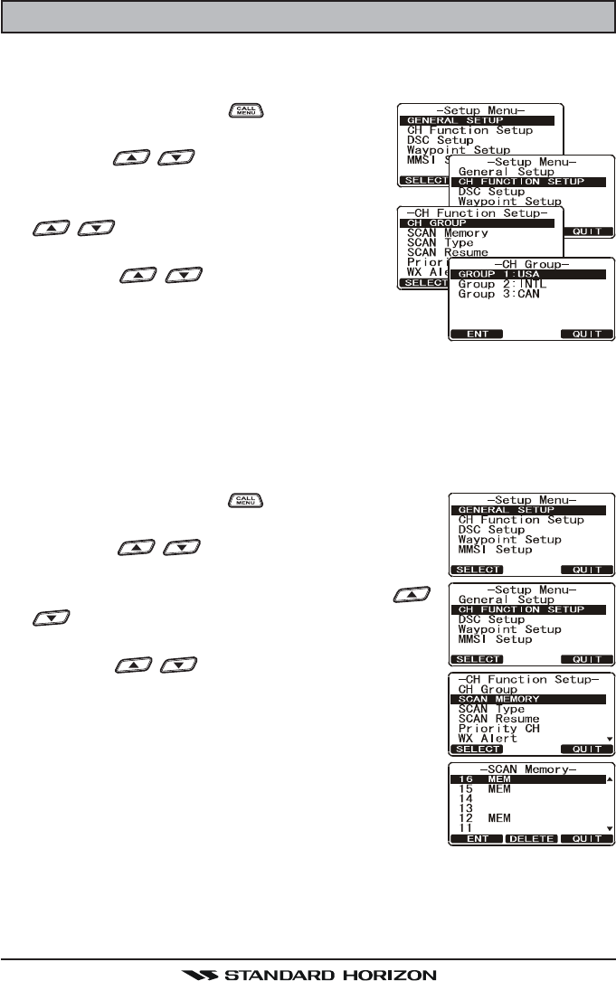
14 CHANNEL FUNCTION SETUP
14.1 CHANNEL GROUP
This section selects a channel group from USA, Canada, and International.
1. Press and hold down the key until “SetupSetup
SetupSetup
Setup
MenuMenu
MenuMenu
Menu” appears.
2. Press the / key to select “CH FUNC-CH FUNC-
CH FUNC-CH FUNC-
CH FUNC-
TION SETUPTION SETUP
TION SETUPTION SETUP
TION SETUP”.
3. Press the [SELECT] soft key, then press the
/ key to select “CH GROUPCH GROUP
CH GROUPCH GROUP
CH GROUP”.
4. Press the [SELECT] soft key.
5. Press the / key to select desired
channel group “USAUSA
USAUSA
USA”, “INTLINTL
INTLINTL
INTL”, or “CANADACANADA
CANADACANADA
CANADA”.
6. Press the [ENT] soft key to store the selected set-
ting.
7. Press the [QUIT] soft key several times to return to radio operation.
14.2 SCAN MEMORY
To be able to scan channels the radio must be programmed. This section al-
lows channels to be stored in scan memory.
1. Press and hold down the key until “Setup MenuSetup Menu
Setup MenuSetup Menu
Setup Menu”
appears.
2. Press the / key to select “CH FUNCTIONCH FUNCTION
CH FUNCTIONCH FUNCTION
CH FUNCTION
SETUPSETUP
SETUPSETUP
SETUP”.
3. Press the [SELECT] soft key, then press the /
key to select “SCAN MEMORYSCAN MEMORY
SCAN MEMORYSCAN MEMORY
SCAN MEMORY”.
4. Press the [SELECT] soft key.
5. Press the / key to select a desired chan-
nel to be scanned, the press the [ADD] key. “MEM”
icon appears on the display, which indicates the
channel has been selected to the scan channel.
6. Repeat step 5 for all the desired channels to be
scanned.
7. To DELETE a channel from the list, select the chan-
nel then press the [DELETE] key. “MEM” icon dis-
appears from the display.
8. When you have completed your selection, press the [QUIT] soft key sev-
eral times to return to radio operation.
FCC ID:K6630483X3D / IC:511B-30483X3S
Vertex Standard Co., Ltd.
GX1600Page 80
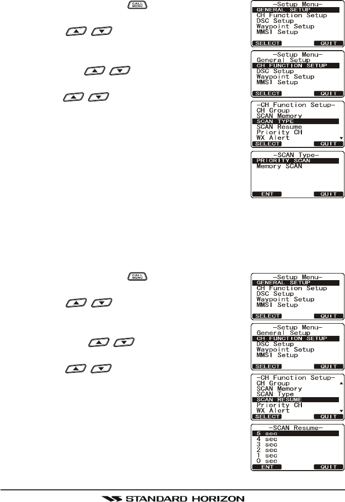
14.3 SCAN TYPE
This selection is used to select the scan mode between “Memory Scan” and
“Priority Scan”. The default setting is Priority Scan.
1. Press and hold down the key until “Setup MenuSetup Menu
Setup MenuSetup Menu
Setup Menu”
appears.
2. Press the / key to select “CH FUNCTIONCH FUNCTION
CH FUNCTIONCH FUNCTION
CH FUNCTION
SETUPSETUP
SETUPSETUP
SETUP”.
3. Press the [SELECT] soft key, then select “SCANSCAN
SCANSCAN
SCAN
TYPETYPE
TYPETYPE
TYPE” with the / key.
4. Press the [SELECT] soft key.
5. Press the / key to select “PRIORITY SCANPRIORITY SCAN
PRIORITY SCANPRIORITY SCAN
PRIORITY SCAN”
or “MEMORY SCANMEMORY SCAN
MEMORY SCANMEMORY SCAN
MEMORY SCAN”.
6. Press the [ENT] soft key to store the selected set-
ting.
7. Press the [QUIT] soft key several times to return to
radio operation.
14.4 SCAN RESUME
This selection is used to select the time the GX1600 waits after a transmission
ends before the radio start to scan channels again. The default setting is 2
seconds.
1. Press and hold down the key until “Setup MenuSetup Menu
Setup MenuSetup Menu
Setup Menu”
appears.
2. Press the / key to select “CH FUNCTIONCH FUNCTION
CH FUNCTIONCH FUNCTION
CH FUNCTION
SETUPSETUP
SETUPSETUP
SETUP”.
3. Press the [SELECT] soft key, then select “SCAN RE-SCAN RE-
SCAN RE-SCAN RE-
SCAN RE-
SUMESUME
SUMESUME
SUME” with the / key.
4. Press the [SELECT] soft key.
5. Press the / key to select the desired re-
sume time, default is 2 seconds. The resume time
can be set to “1SEC1SEC
1SEC1SEC
1SEC” through “5SEC5SEC
5SEC5SEC
5SEC”, or “OFFOFF
OFFOFF
OFF”. In the
“OFFOFF
OFFOFF
OFF” selection, the scanner will resume after the
other station stops transmitting (carrier drops).
6. Press the [ENT] soft key to store the selected set-
ting.
7. Press the [QUIT] soft key several times to return to
radio operation.
FCC ID:K6630483X3D / IC:511B-30483X3S
Vertex Standard Co., Ltd.
Page 81GX1600
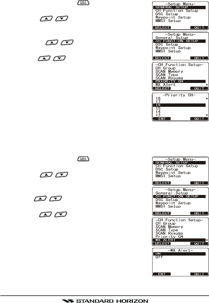
14.5 PRIORITY CHANNEL
By default the radio priority channel is set to channel 16. This procedure allows
the radio to use a different priority channel used when priority scanning.
1. Press and hold down the key until “Setup MenuSetup Menu
Setup MenuSetup Menu
Setup Menu”
appears.
2. Press the / key to select “CH FUNCTIONCH FUNCTION
CH FUNCTIONCH FUNCTION
CH FUNCTION
SETUPSETUP
SETUPSETUP
SETUP”.
3. Press the [SELECT] soft key, then select “PRIORITYPRIORITY
PRIORITYPRIORITY
PRIORITY
CHCH
CHCH
CH” with the / key.
4. Press the [SELECT] soft key.
5. Press the / key to select the desired chan-
nel to be a priority.
6. Press the [ENT] soft key to store the selected set-
ting.
7. Press the [QUIT] soft key several times to return to
radio operation.
14.6 WEATER ALERT
This menu selection allows the WX Alert to be changed. The default setting is
On Scan and WX channel.
1. Press and hold down the key until “Setup MenuSetup Menu
Setup MenuSetup Menu
Setup Menu”
appears.
2. Press the / key to select “CH FUNCTIONCH FUNCTION
CH FUNCTIONCH FUNCTION
CH FUNCTION
SETUPSETUP
SETUPSETUP
SETUP”.
3. Press the [SELECT] soft key, then select “WX ALERTWX ALERT
WX ALERTWX ALERT
WX ALERT”
with the / key.
4. Press the [SELECT] soft key.
5. Press the / key to select the desired WX
alert mode. The WX alert mode can be set to “ONON
ONON
ON”
or “OFFOFF
OFFOFF
OFF”.
6. Press the [ENT] soft key to store the selected set-
ting.
7. Press the [QUIT] soft key several times to return to
radio operation.
FCC ID:K6630483X3D / IC:511B-30483X3S
Vertex Standard Co., Ltd.
GX1600Page 82
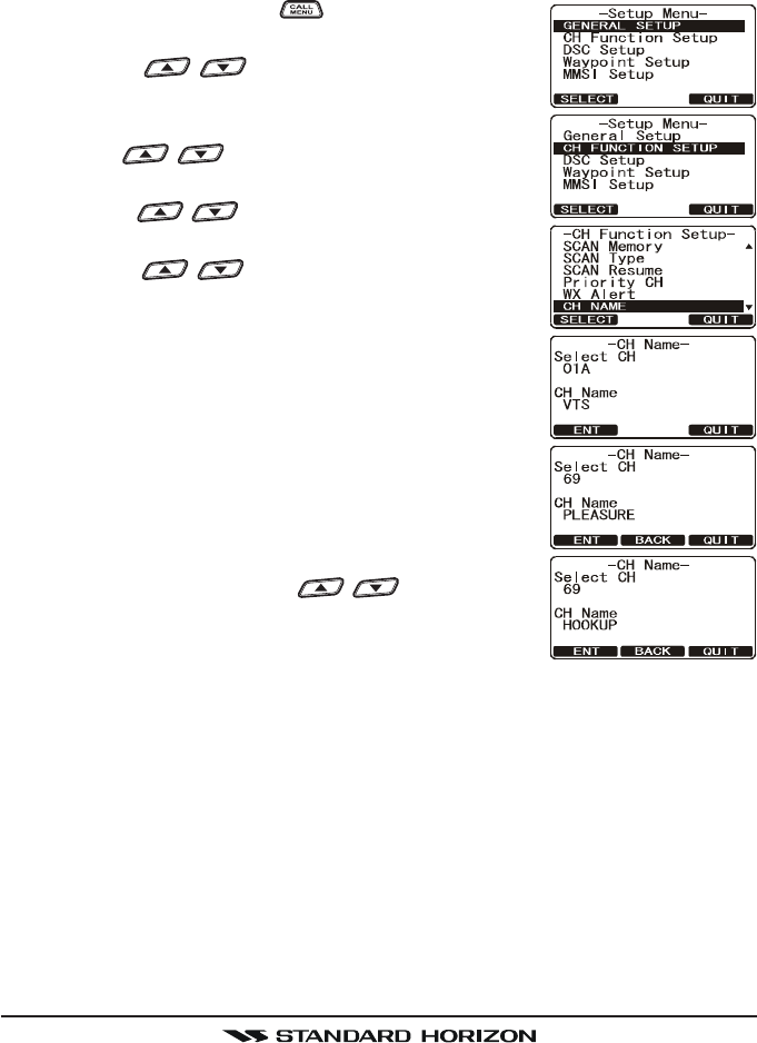
14.7 CHANNEL NAME
When radio mode (NORMAL) is selected, the display will show a name under
the channel number. This name describes the use of the channel. The radio
has the capability to customize the name by the procedure below.
Example: CH69 PLEASURE to HOOKUP
1. Press and hold down the key until “Setup MenuSetup Menu
Setup MenuSetup Menu
Setup Menu”
appears.
2. Press the / key to select “CH FUNCTIONCH FUNCTION
CH FUNCTIONCH FUNCTION
CH FUNCTION
SETUPSETUP
SETUPSETUP
SETUP”.
3. Press the [SELECT] soft key, then select “CH NAMECH NAME
CH NAMECH NAME
CH NAME”
with the / key.
4. Press the [SELECT] soft key.
5. Press the / key to select the channel to be
named, then press the [ENT] soft key.
6. Press the / key to scroll through the first
letter of the new channel name.
7. Press the [ENT] soft key to store the first letter in
the name and step to the next letter to the right.
8. Repeat step 6 and 7 until the name is complete.
The name can consist of up to 16 characters, if you
do not use all 16 characters press the [ENT] soft
key to move to the next space. This method can
also be used to enter a blank space in the name. If
a mistake was made entering in the name repeat
pressing the [BACK] key until the wrong character
is selected, then press the / key to correct
the entry.
9. Press and hold the [ENT] soft key to save the name.
10. If you want to enter the name of another channel, repeat steps 5 through 9.
11. Press the [QUIT] soft key several times to return to radio operation.
FCC ID:K6630483X3D / IC:511B-30483X3S
Vertex Standard Co., Ltd.
Page 83GX1600
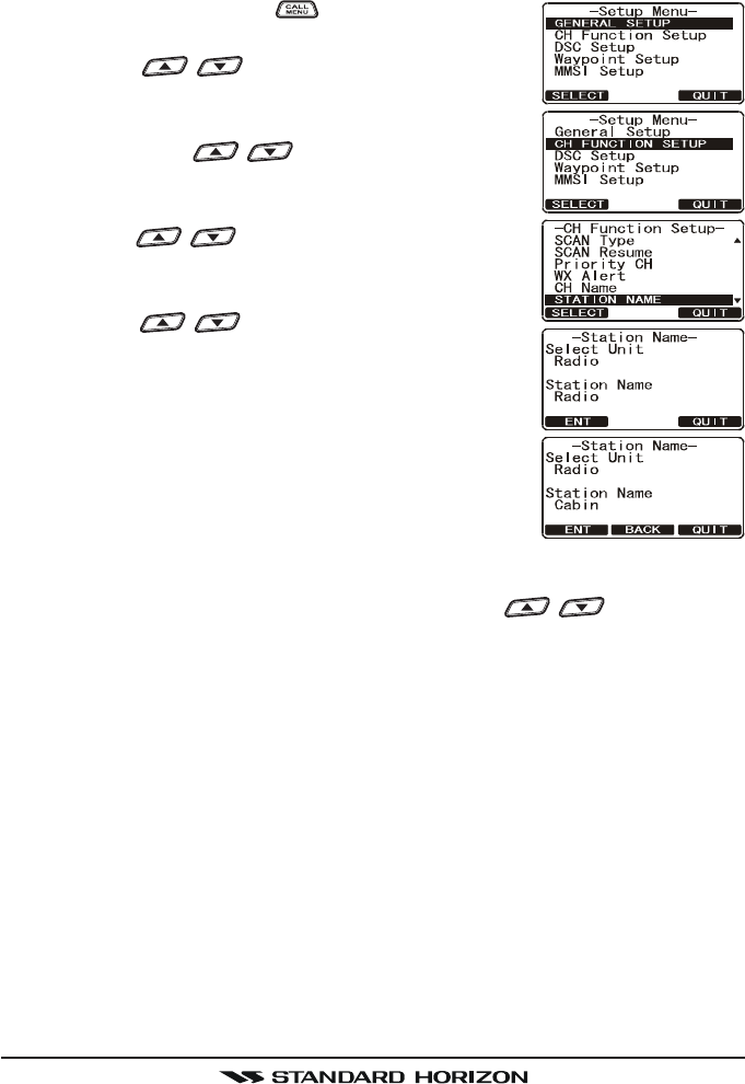
14.8 STATION NAME
This function allows you to change the name of the radio or second station
microphone. Example: “Radio - Cabin”, “RAM1 - Flybridge”.
1. Press and hold down the key until “Setup MenuSetup Menu
Setup MenuSetup Menu
Setup Menu”
appears.
2. Press the / key to select “CH FUNCTIONCH FUNCTION
CH FUNCTIONCH FUNCTION
CH FUNCTION
SETUPSETUP
SETUPSETUP
SETUP”.
3. Press the [SELECT] soft key, then select “STATIONSTATION
STATIONSTATION
STATION
NAMENAME
NAMENAME
NAME” with the / key.
4. Press the [SELECT] soft key.
5. With the second station microphone connected,
press the / key to select the Unit (“RadioRadio
RadioRadio
Radio”
or “RAM1RAM1
RAM1RAM1
RAM1”) to be named, then press the [ENT] soft
key.
6. Press the / key to scroll through the first
letter of the new channel name.
7. Press the [ENT] soft key to store the first letter in
the name and step to the next letter to the right.
8. Repeat step 6 and 7 until the name is complete.
The name can consist of up to 8 characters, if you
do not use all 8 characters press the [ENT] soft key
to move to the next space. This method can also be
used to enter a blank space in the name. If a mis-
take was made entering in the name repeat pressing the [BACK] key until
the wrong character is selected, then press the / key to correct
the entry.
9. Press and hold the [ENT] soft key to enter the name.
10. If you want to enter the name of the connected RAM3 or Radio, repeat
steps 5 through 9.
11. Press the [QUIT] soft key several times to return to radio operation.
FCC ID:K6630483X3D / IC:511B-30483X3S
Vertex Standard Co., Ltd.
GX1600Page 84
15 DSC SETUP
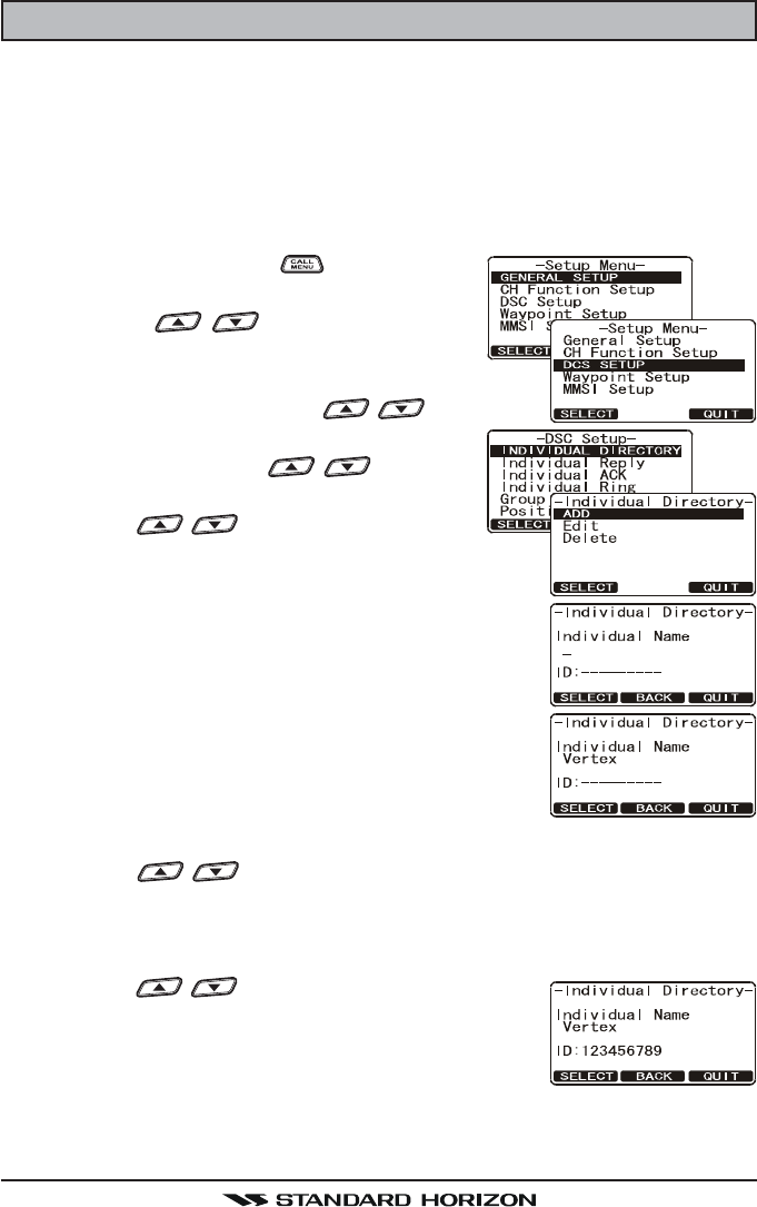
15.1 INDIVIDUAL DIRECTORY
The GX2000/GX2100 has a DSC directory that allows you to store a vessel or
person’s name and the MMSI number associated with vessels you wish to
transmit Individual calls, Position Requests and Position Send transmissions.
To transmit an Individual call you must program this directory with information
of the persons you wish to call, similar to a cellular phones telephone directory.
1. Press and hold down the key until “SetupSetup
SetupSetup
Setup
MenuMenu
MenuMenu
Menu” appears.
2. Press the / key to select “DSCDSC
DSCDSC
DSC
SETUPSETUP
SETUPSETUP
SETUP” menu.
3. Press the [SELECT] soft key, then select “INDI-INDI-
INDI-INDI-
INDI-
VIDUAL DIRECTORYVIDUAL DIRECTORY
VIDUAL DIRECTORYVIDUAL DIRECTORY
VIDUAL DIRECTORY” with the / key.
4. Press the [SELECT] soft key.
5. Select “ADDADD
ADDADD
ADD” with the / key, then
press the [SELECT] soft key.
6. Press the / key to scroll through the
first letter of the name of the vessel or person you
want to reference in the directory.
7. Press the [ENT] soft key to store the first letter in
the name and step to the next letter to the right.
8. Repeat step 6 and 7 until the name is complete.
The name can consist of up to eleven characters, if
you do not use all eleven characters press the [ENT]
soft key to move to the next space. This method
can also be used to enter a blank space in the name.
If a mistake was made entering in the name repeat
pressing the [BACK] soft key until the wrong character is selected, then
press the / key to correct the entry.
9. After the eleventh letter or space has been entered, press and hold the
[ENT] soft key to advance to the MMSI (Maritime Mobile Service Identity
Number) number entry.
10. Press the / key to scroll through numbers,
0-9. To enter the desired number and move one
space to the right by pressing the [ENT] soft key.
Repeat this procedure until all nine space of the
MMSI number are entered.
11. If a mistake was made entering in the MMSI number repeat pressing the
[BACK] soft key until the wrong number is selected, then rotate the CHAN-
FCC ID:K6630483X3D / IC:511B-30483X3S
Vertex Standard Co., Ltd.
Page 85GX1600
NEL knob to correct the entry.
12. To store the data entered, press and hold the [ENT] soft key.
13. To enter another individual address, repeat steps 5 through 12.
14. Press the [QUIT] soft key several times to return to radio operation.
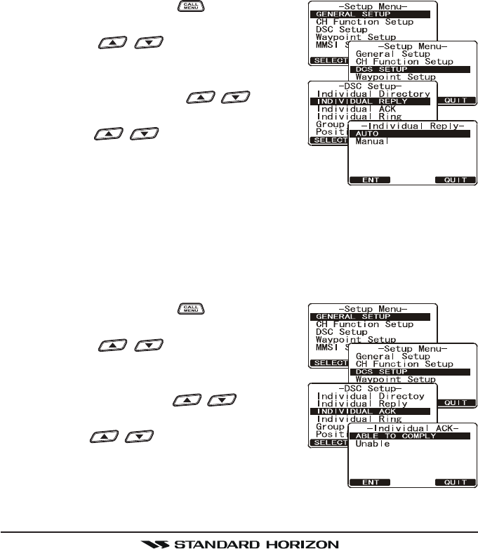
15.2 INDIVIDUAL REPLY
This menu item sets up the radio to automatically (default setting) or manually
respond to a DSC Individual call requesting you to switch to a working channel
for voice communications. When Manual is selected the MMSI of the calling
vessel is shown allowing you to see who is calling. This function is similar to
caller id on a cellular phone.
1. Press and hold down the key until “SetupSetup
SetupSetup
Setup
MenuMenu
MenuMenu
Menu” appears.
2. Press the / key to select “DSCDSC
DSCDSC
DSC
SETUPSETUP
SETUPSETUP
SETUP” menu.
3. Press the [SELECT] soft key, then select “IN-IN-
IN-IN-
IN-
DIVIDUAL REPLYDIVIDUAL REPLY
DIVIDUAL REPLYDIVIDUAL REPLY
DIVIDUAL REPLY” with the / key.
4. Press the [SELECT] soft key.
5. Press the / key to select “AUTO-AUTO-
AUTO-AUTO-
AUTO-
MATICMATIC
MATICMATIC
MATIC” or “MANUALMANUAL
MANUALMANUAL
MANUAL”.
6. Press the [SELECT] soft key to store the selected
setting.
7. Press the [QUIT] soft key several times to return to radio operation.
15.3 INDIVIDUAL ACKNOWLEDGMENT
The radio can be setup to transmit a reply automatically (default) or set so the
radio will not reply to an individual call.
1. Press and hold down the key until “SetupSetup
SetupSetup
Setup
MenuMenu
MenuMenu
Menu” appears.
2. Press the / key to select “DSCDSC
DSCDSC
DSC
SETUPSETUP
SETUPSETUP
SETUP” menu.
3. Press the [SELECT] soft key, then select “IN-IN-
IN-IN-
IN-
DIVIDUAL ACKDIVIDUAL ACK
DIVIDUAL ACKDIVIDUAL ACK
DIVIDUAL ACK” with the / key.
4. Press the [SELECT] soft key.
5. Press the / key to select “ABLE TOABLE TO
ABLE TOABLE TO
ABLE TO
COMPLYCOMPLY
COMPLYCOMPLY
COMPLY” or “UNABLEUNABLE
UNABLEUNABLE
UNABLE”.
6. Press the [SELECT] soft key to store the selected
setting.
7. Press the [QUIT] soft key several times to return to radio operation.
FCC ID:K6630483X3D / IC:511B-30483X3S
Vertex Standard Co., Ltd.
GX1600Page 86
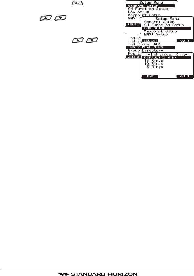
15.4 INDIVIDUAL RINGER
The radio can be setup to ring like a telephone to alert you the radio received
a DSC Individual call. The default setting is 2 minutes, however this can be
changed to 15, 10 or 5 seconds with the procedure below.
1. Press and hold down the key until “SetupSetup
SetupSetup
Setup
MenuMenu
MenuMenu
Menu” appears.
2. Press the / key to select “DSCDSC
DSCDSC
DSC
SETUPSETUP
SETUPSETUP
SETUP” menu.
3. Press the [SELECT] soft key, then select “IN-IN-
IN-IN-
IN-
DIVIDUAL RINGDIVIDUAL RING
DIVIDUAL RINGDIVIDUAL RING
DIVIDUAL RING” with the / key.
4. Press the [SELECT] soft key.
5. Rotate the CHANNEL knob to select ringing
time of a Individual Call.
6. Press the [ENT] soft key to store the selected set-
ting.
7. Press the [QUIT] soft key several times to return to radio operation.
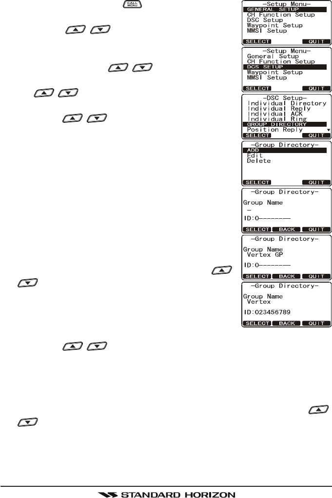
15.5 GROUP DIRECTORY
For this function to operate, the same Group MMSI must be programmed into
all the DSC VHF radios within the group of vessels that will be using this fea-
ture. To understand Group MMSI programming, first a Ship MMSI has to be
understood.
Ship MMSI: The first three digits called a MID (Mobile Identity Group) of a Ship
MMSI denote the country the ship registered for a MMSI. The last 6 digits are
specific to the Ships ID.
Ship MMSI Example: If your MMSI is “366123456”, “366” is MID which denote
the country and “123456” is your ships MMSI.
Group MMSI:
Group MMSI numbers are not assigned by the FCC or other organizations
licensed to assign ship MMSI numbers.
The first digit of a Group MMSI is always set to “0” by International rules.
All Standard Horizon radios are preset so when programming a Group
MMSI the first digit is set to “0”.
The USCG recommends programming the MID of a ships MMSI into the
Second, Third and Fourth digits of the Group MMSI as it denotes the area
the ship is located in.
The last 5 digits are decided upon by persons in the Group. This is an
important step as all radios in the Group must contain the same Group
MMSI so they can be contacted by each other. There is a chance that
FCC ID:K6630483X3D / IC:511B-30483X3S
Vertex Standard Co., Ltd.
Page 87GX1600
another group of vessels may program in the same Group MMSI. If this
happens, simply change one or more of the last 5 digits of the Group MMSI.
1. Press and hold down the key until “Setup MenuSetup Menu
Setup MenuSetup Menu
Setup Menu”
appears.
2. Press the / key to select “DSC SETUPDSC SETUP
DSC SETUPDSC SETUP
DSC SETUP”
menu.
3. Press the [SELECT] soft key, then select “GROUPGROUP
GROUPGROUP
GROUP
DIRECTORYDIRECTORY
DIRECTORYDIRECTORY
DIRECTORY” with the / key.
4. Press the [SELECT] soft key, then select “ADDADD
ADDADD
ADD” with
the / key.
5. Press the [SELECT] soft key.
6. Press the / key to scroll through the first
letter of the name of the group you want to refer-
ence in the directory.
7. Press the [SELECT] soft key to store the first letter
in the name and step to the next letter to the right.
8. Repeat step 6 and 7 until the name is complete.
The name can consist of up to eleven characters, if
you do not use all eleven characters press the [SE-
LECT] soft key to move to the next space. This
method can also be used to enter a blank space in
the name. If a mistake was made entering in the
name repeat pressing the [BACK] soft key until the
wrong character is selected, then press the /
key to correct the entry.
9. After the eleventh letter or space has been entered,
press and hold the [SELECT] soft key to advance
to the GROUP MMSI (Maritime Mobile Service Iden-
tity Number) number entry.
10. Press the / key to select the second number of the MMSI (nine
digits: first digit permanently set to “0”) which you want to contact, then
press the [SELECT] soft key to step to the next number. Repeat this proce-
dure until all eight space of the MMSI number are entered.
11. If a mistake was made entering in the MMSI number repeat pressing the
[BACK] soft key until the wrong number is selected, then press the /
key to correct the entry.
12. To store the data entered, press and hold the [SELECT] soft key.
13. To enter another group address, repeat steps 5 through 12.
14. Press the [QUIT] soft key several times to return to radio operation.
FCC ID:K6630483X3D / IC:511B-30483X3S
Vertex Standard Co., Ltd.
GX1600Page 88
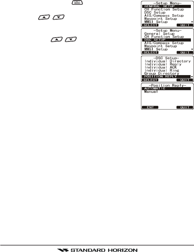
15.6 POSITION REPLY
The GX1600 can be set up to automatically (default setting) or manually send
your position when requested by another vessel. This selection is important if
you are concerned about someone polling the position of your vessel that you
may not want to. In the manual mode you will see the MMSI or persons name
shown on the display allowing you to choose to send your position to the re-
questing vessel.
1. Press and hold down the key until “Setup MenuSetup Menu
Setup MenuSetup Menu
Setup Menu”
appears.
2. Press the / key to select “DSC SETUPDSC SETUP
DSC SETUPDSC SETUP
DSC SETUP”
menu.
3. Press the [SELECT] soft key, then select “POSITIONPOSITION
POSITIONPOSITION
POSITION
REPLYREPLY
REPLYREPLY
REPLY” with the / key.
4. Press the [SELECT] soft key, then select “AUTO-AUTO-
AUTO-AUTO-
AUTO-
MATICMATIC
MATICMATIC
MATIC” or “MANUALMANUAL
MANUALMANUAL
MANUAL”. In “AUTOMATICAUTOMATIC
AUTOMATICAUTOMATIC
AUTOMATIC” mode, after
a DSC POS Request is received, the radio will au-
tomatically transmit your vessels position. In
“MANUALMANUAL
MANUALMANUAL
MANUAL” mode, the display of the GX1600 will
show who is requesting the position and the YES
soft key on radio has to be pressed to send your
position to the requesting.
5. Press the [ENT] soft key to store the selected set-
ting.
6. Press the [QUIT] soft key several times to return to radio operation.
FCC ID:K6630483X3D / IC:511B-30483X3S
Vertex Standard Co., Ltd.
Page 89GX1600
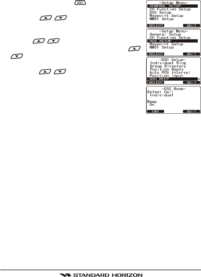
15.7 DSC BEEP
This feature allows the alarm beeps to be turned on (default setting) or off
when a DSC call is received. The DSC calls that can be customized are: Indi-
vidual, Group, All Ships, Position Request, Position Report, Geographic Call
using the procedure below:
1. Press and hold down the key until “Setup MenuSetup Menu
Setup MenuSetup Menu
Setup Menu”
appears.
2. Press the / key to select “DSC SETUPDSC SETUP
DSC SETUPDSC SETUP
DSC SETUP”
menu.
3. Press the [SELECT] soft key, then select “DSC BEEPDSC BEEP
DSC BEEPDSC BEEP
DSC BEEP”
with the / key.
4. Press the [SELECT] soft key, then press the /
key to the desired DSC call type and press
the [ENT] soft key.
5. Press the / key to turn “OnOn
OnOn
On” or “OffOff
OffOff
Off” the
DSC beep and press the [ENT] soft key.
6. Press the [QUIT] soft key several times to return to
radio operation.
FCC ID:K6630483X3D / IC:511B-30483X3S
Vertex Standard Co., Ltd.
GX1600Page 90
16 WAYPOINTS
The GX1600 is capable of storing up to 100 waypoint and navigating to them
using the compass page.
In addition DSC distress calls with position or a position received from a an-
other DSC radio using DSC polling can be navigated to.
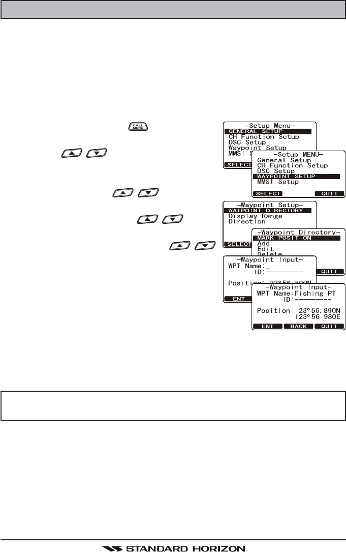
16.1 MARKING A POSITION
This feature allows the radio to mark the current position of the vessel.
1. Press and hold down the key until “SetupSetup
SetupSetup
Setup
MenuMenu
MenuMenu
Menu” appears.
2. Press the / key to select “WAYPOINTWAYPOINT
WAYPOINTWAYPOINT
WAYPOINT
SETUPSETUP
SETUPSETUP
SETUP”.
3. Press the [SELECT] soft key, then select “WAYPOINTWAYPOINT
WAYPOINTWAYPOINT
WAYPOINT
DIRECTORYDIRECTORY
DIRECTORYDIRECTORY
DIRECTORY” with the / key.
4. Press the [SELECT] soft key, then select
“MARK POSITIONMARK POSITION
MARK POSITIONMARK POSITION
MARK POSITION” with the / key.
5. Press the [SELECT] soft key, then enter the
Waypoint Name, by pressing the /
key to select the first letter.
6. Press the [ENT] soft key to store the first let-
ter and to move to the second letter in the
name.
7. Repeat step 5 and 6 until the name is shown. Press
the [ENT] soft key to skip a letter if needed.
8. Press and hold the [ENT] soft key two times to save the waypoint into
memory.
9. Press the [QUIT] soft key several times to return to radio operation.
NOTE
If you assign the “Mark” function to the Soft key, you may recall the
“Waypoint Input” directly by pressing the [ENT] soft key.
FCC ID:K6630483X3D / IC:511B-30483X3S
Vertex Standard Co., Ltd.
Page 91GX1600
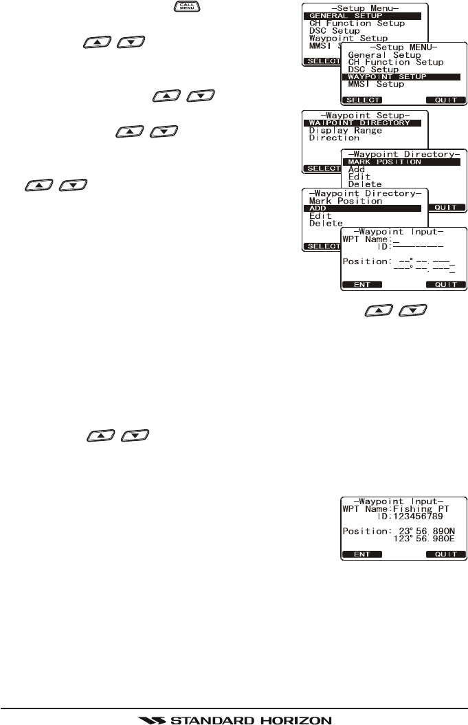
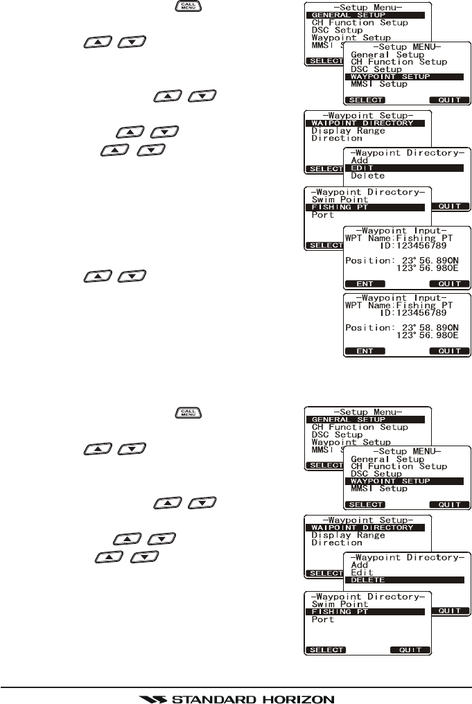
16.2 ADDING A WAYPOINT
1. Press and hold down the key until “SetupSetup
SetupSetup
Setup
MenuMenu
MenuMenu
Menu” appears.
2. Press the / key to select “WAYPOINTWAYPOINT
WAYPOINTWAYPOINT
WAYPOINT
SETUPSETUP
SETUPSETUP
SETUP”.
3. Press the [SELECT] soft key, then select “WAYPOINTWAYPOINT
WAYPOINTWAYPOINT
WAYPOINT
DIRECTORYDIRECTORY
DIRECTORYDIRECTORY
DIRECTORY” with the / key.
4. Press the [SELECT] soft key, then select
“ADDADD
ADDADD
ADD” with the / key.
5. Press the [SELECT] soft key.
6. Enter the Waypoint Name, by pressing the
/ key to select the first letter.
7. Press the [ENT] soft key to store the first let-
ter and to move to the second letter in the
name.
8. Repeat step 5 and 6 until the name is shown.
Press the [ENT] soft key to skip a letter if needed.
9. Press and hold the [ENT] soft key, then enter the
coordinates of the waypoint POSITION, by pressing the / key to
select the first digit in the Latitude.
10. Press the [ENT] soft key to store the first number and to move to the sec-
ond number in the position.
11. Repeat step 9 and 10 until the latitude is shown include N or S in the last
digit.
12. Press the [ENT] soft key to select the first digit of the Longitude is blinking.
13. Press the / key to select the first digit in the Longitude.
14. Press the [ENT] soft key to store the first number and to move to the sec-
ond number in the position.
15. Repeat step 13 and 14 until the Latitude is shown
include E or W in the last digit.
16. After all information is entered, press and hold the
[ENT] soft key to store the waypoint into memory.
17. Press the [QUIT] soft key several times to return to
radio operation.
FCC ID:K6630483X3D / IC:511B-30483X3S
Vertex Standard Co., Ltd.
GX1600Page 92
16.3 EDITING A WAYPOINT
This function allows a previously entered waypoint to be edited.
1. Press and hold down the key until “SetupSetup
SetupSetup
Setup
MenuMenu
MenuMenu
Menu” appears.
2. Press the / key to select “WAYPOINTWAYPOINT
WAYPOINTWAYPOINT
WAYPOINT
SETUPSETUP
SETUPSETUP
SETUP”.
3. Press the [SELECT] soft key, then select “WAYPOINTWAYPOINT
WAYPOINTWAYPOINT
WAYPOINT
DIRECTORYDIRECTORY
DIRECTORYDIRECTORY
DIRECTORY” with the / key.
4. Press the [SELECT] soft key, then select
“EDITEDIT
EDITEDIT
EDIT” with the / key.
5. Press the / key to select the
waypoint to be edited.
6. Press the [ENT] soft key to show the waypoint
Input display.
7. Press the [ENT] soft key repeatedly until the
number or letter is selected that is to be
changed.
8. Press the / key to change the letter or num-
ber.
9. Repeat step 7 and 8 until the waypoint is updated.
10. Press and hold the [ENT] soft key to store the ed-
ited waypoint into memory.
11. Press the [QUIT] soft key several times to return to radio operation.
16.4 DELETING A WAYPOINT
1. Press and hold down the key until “SetupSetup
SetupSetup
Setup
MenuMenu
MenuMenu
Menu” appears.
2. Press the / key to select “WAYPOINTWAYPOINT
WAYPOINTWAYPOINT
WAYPOINT
SETUPSETUP
SETUPSETUP
SETUP”.
3. Press the [SELECT] soft key, then select “WAYPOINTWAYPOINT
WAYPOINTWAYPOINT
WAYPOINT
DIRECTORYDIRECTORY
DIRECTORYDIRECTORY
DIRECTORY” with the / key.
4. Press the [SELECT] soft key, then select “DE-DE-
DE-DE-
DE-
LETELETE
LETELETE
LETE” with the / key.
5. Press the / key to highlight the
waypoint to be deleted.
6. Press and hold the [ENT] soft key until the
radio beeps and the waypoint directory is re-
moved from the display.
7. Press the [QUIT] soft key several times to
return to radio operation.
FCC ID:K6630483X3D / IC:511B-30483X3S
Vertex Standard Co., Ltd.
Page 93GX1600
16.5 SAVING A DSC POSITION CALL AS A WAYPOINT
When a position is received from a another DSC radio the GX2000/GX2100
allows the position to be saved as a waypoint.
1. After a position has been received, press the
[SAVE] soft key two times.
2. The first digit in the WPT Name will be flash-
ing, press the / key to the first letter
of the name you want to input.
3. Press the [ENT] soft key, then press the /
key to select the second letter in the name.
4. Repeat step 3 until the name is shown.
5. Press and hold the [ENT] soft key until the radio
beeps to save the waypoint to memory.
6. Press the [QUIT] soft key several times to return to radio operation.
16.6 NAVIGATING TO A SAVED WAYPOINT
1. Press and hold down the key until “SetupSetup
SetupSetup
Setup
MenuMenu
MenuMenu
Menu” appears.
2. Press the / key to select “GENERALGENERAL
GENERALGENERAL
GENERAL
SETUPSETUP
SETUPSETUP
SETUP”.
3. Press the [SELECT] soft key, then select “DIS-DIS-
DIS-DIS-
DIS-
PLAYPLAY
PLAYPLAY
PLAY” with the / key.
4. Press the [ENT] soft key, and select
“WAYPOINTWAYPOINT
WAYPOINTWAYPOINT
WAYPOINT”, and press the [SELECT] soft
key.
5. Select the waypoint name and press the [ENT]
soft key to show the waypoint data display.
6. Press the [ENT] soft key to start navigating
the waypoint and show the Waypoint Nav display.
NOTE
The radio must be connected to a GPS to be able to navigate to a
waypoint.
FCC ID:K6630483X3D / IC:511B-30483X3S
Vertex Standard Co., Ltd.

GX1600Page 94
16.7 STOP NAVIGATING TO A WAYPOINT
To stop navigating to a waypoint, press the one of the
Soft keys, then press the [STOP] soft key. The radio is
switched to Normal Mode.
FCC ID:K6630483X3D / IC:511B-30483X3S
Vertex Standard Co., Ltd.

Page 95GX1600
MEMO
FCC ID:K6630483X3D / IC:511B-30483X3S
Vertex Standard Co., Ltd.
GX1600Page 96
17 CMP30 (RAM3) REMOTE MIC OPERATION
When the Remote MIC is connected to the GX1600, all VHF, DSC, setup menus,
AIS, Waypoint, Compass functions and PA/Fog modes can be remotely oper-
ated. The CMP30’s operation is same as GX1600 except the receiver audio
volume setting and squelch level setting. The reason for the same operation is
to make the operation of the radio and CMP30 mic easy. For specific operation
of the CMP30 mic review sections in the radio manual. The CMP30 is supplied
with 23 feet (7 m) of routing cable and can be extended up to 70 feet (21 m)
using three 23-foot extension cables model CT-100. The Intercom feature can
be used between the CMP30 and the GX1600. In addition, speaker wires are
supplied at the panel mount of the routing cable for external speakers to be
connected in noisy environments.
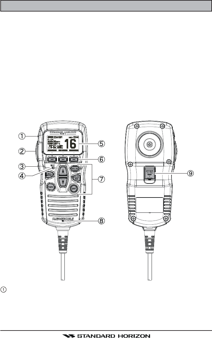
17.1 REMOTE MIC CONTROLS
[H/L] KEY
Toggles between high and low power. When the [H/L] key is pressed while
the transceiver is on CH13 or CH67, the power is temporarily switched
from LO to HI until the PTT switch is released. The [H/L] key does not
function on transmit inhibited and low-power only channels.
FCC ID:K6630483X3D / IC:511B-30483X3S
Vertex Standard Co., Ltd.

Page 97GX1600
PTT (Push-To-Talk) Key
Push this key to enable the transmitter.
POWER ( ) Key
Press and hold down this key to turn the transceiver and Remote MIC on
or off.
MICROPHONE
The internal ClearVoice Noise Canceling mic is located here..
When transmitting, position your mouth about 1/2 to 1 inch (1.2 ~ 2.5 cm)
away from the small mic hole. Speak slowly and clearly into the micro-
phone.
DISPLAY
Full dot matrix display.
SOFT KEY
These three key’s functions can be customized by the Setup Menu mode.
When press one of these key briefly, the key functions will appear at the
bottom of the display. Refer to section “17.2 ASSIGNING SOFT KEYS” for
details.
KEY PAD
[CALL/MENU] Key
Press this key to access the DSC menu.
Press and hold this key to access the SETUP menu.
[16/9] Key
First press: channel 16 is immediately selected.
Second press: recalls the last selected channel.
Press and hold: selects channel 9.
[](UP)/[](DOWN) Key
These keys are used to select channels, adjust the volume and squelch
level, and to choose DSC calls, DSC setup and Radio setup function.
[VOL/SQ] Key (Volume Control / Squelch Control)
First press: Volume adjustment mode
Second press: Squelch adjustment mode
Third press: exits adjustment mode
When in volume or squelch mode, press the [] or [] keys to adjust
the level.
FCC ID:K6630483X3D / IC:511B-30483X3S
Vertex Standard Co., Ltd.
GX1600Page 98
[CLR/WX] Key
Press to CLEAR a function or menu selection. Press and hold to select
NOAA Weather channels. Press and hold again to exit Weather mode
and revert to radio mode.
Secondary use
Hold down the [16/9] key while pressing the [WX] key to change the
mode from USA to International or Canadian.
[ENT] Key
This key functions as the enter key.
SPEAKER
The internal speaker is located here.
[DISTRESS] KEY
Used to send a DSC Distress call. Refer to section “11 DIGITAL SELEC-
TIVE CALLING”.
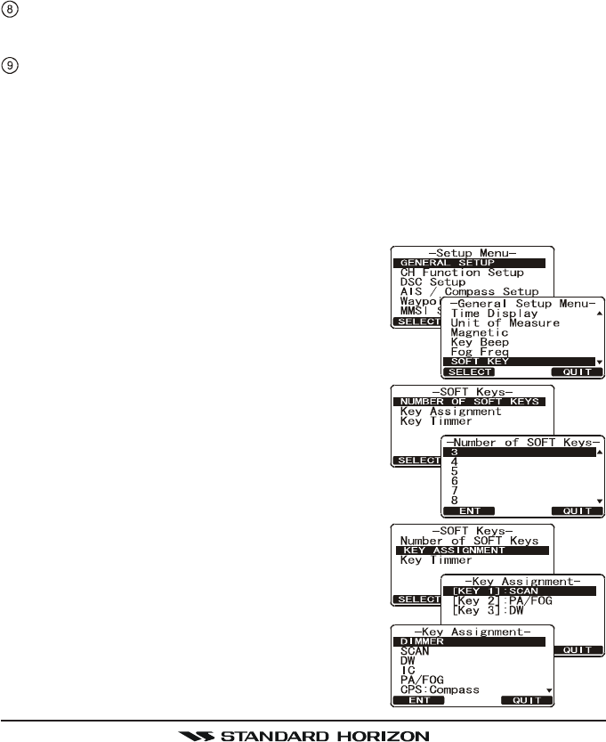
17.2 ASSIGNING SOFT KEYS
This menu item allows selection of the number of soft keys, soft key selection
and how long the display will show the soft key icon after a soft key is pressed.
The keys maybe setup to control the following functions:
1. Press and hold down the [CALL/MENU] key
until “Setup MenuSetup Menu
Setup MenuSetup Menu
Setup Menu” appears, then select “GEN-GEN-
GEN-GEN-
GEN-
ERAL SETUPERAL SETUP
ERAL SETUPERAL SETUP
ERAL SETUP” with the [] or [] key.
2. Press the [SELECT] soft key, then press the
[] key to select “SOFT KEYSOFT KEY
SOFT KEYSOFT KEY
SOFT KEY”.
3. Press the [SELECT] soft key, then press the []
key to select “NUMBER OF SOFT KEYSNUMBER OF SOFT KEYS
NUMBER OF SOFT KEYSNUMBER OF SOFT KEYS
NUMBER OF SOFT KEYS”.
4. Press the [SELECT] soft key, then press the
[] or [] key to select the number of soft keys
(3 through 10).
5. Press the [ENT] soft key, then press the [] key to
select “KEY ASSIGNMENTKEY ASSIGNMENT
KEY ASSIGNMENTKEY ASSIGNMENT
KEY ASSIGNMENT” (to change the use of se-
lected soft keys). Then press the [SELECT] soft
key.
6. Press the [] or [] key to select the key
(“KEY1KEY1
KEY1KEY1
KEY1”, “KEY2KEY2
KEY2KEY2
KEY2”, “KEY3KEY3
KEY3KEY3
KEY3” etc), and press the
[SELECT] soft key. Then press the [] or []
key to select the new function to be assigned,
and press the [ENT] soft key. Available func-
tions are listed next page. Repeat step 6 to
FCC ID:K6630483X3D / IC:511B-30483X3S
Vertex Standard Co., Ltd.
Page 99GX1600
program the other soft keys.
7. Press the [QUIT] soft key, then press the []
or [] key to select “KEY TIMERKEY TIMER
KEY TIMERKEY TIMER
KEY TIMER” (selects how
long the soft key icon will be shown on the
display after a soft key is pressed, default is 5
seconds). Then, press the [SELECT] soft key.
8. Press the [] or [] key to select the time.
9. Press the [ENT] soft key to store the selected setting.
10. Press the [QUIT] soft key several times to return to radio operation.
DISPLAY
SCAN
DW
IC
CMP: COMPASS
WPT
PRESET
WX
MARK
PRESET 0 - 9
FUNCTION
Starts and stops Scanning.
Starts and stops Dual Watch Scan.
Activates Intercom between radio and RAM3 mic (optional RAM3 required).
Shows to the “Compass” display.
Shows to the “Waypoint” Navigation display.
Porgrams or deletes the preset memory channel.
Immediately recalls the last select the weather channel.
Marks the current position for the “Waypoint”.
Immediately recalls the preset memory channel.
FCC ID:K6630483X3D / IC:511B-30483X3S
Vertex Standard Co., Ltd.

GX1600Page 100
18 MAINTENANCE
The inherent quality of the solid-state components used in this transceiver will
provide many years of continuous use. Taking the following precautions will
prevent damage to the transceiver.
• Keep the microphone connected or the jack covered at all times to prevent
corrosion of electrical contacts;
• Never key the microphone unless an antenna or suitable dummy load is
connected to the transceiver.
• Ensure that the supply voltage to the transceiver does not exceed 16 VDC
or fall below 11 VDC.
• Use only STANDARD HORIZON-approved accessories and replacement
parts.
In the unlikely event of serious problems, please contact your Dealer or our
repair facility. Address and phone numbers for this facility, as well as warranty
information, are contained in section “19 WARRANTY.”
18.1 REPLACEMENT PARTS
Occasionally an owner needs a replacement mounting bracket or knob.
These can be ordered from our Parts Department by writing or calling:
Marine Division of Vertex Standard
US Headquarters
10900 Walker Street, Cypress, CA 90630, U.S.A.
Telephone (714) 827-7600
Commonly requested parts, and their part numbers are listed below.
•Power Cord: T9025406
•Panel Cover: RA1298700
•VOL and SQL Knob: RA1282500 (White), RA1282600 (Black)
•Mounting Bracket: RA1283100 (White), RA1283200 (Black)
•Mounting Bracket Knob: RA0978500 (White), RA0978600 (Black)
•Microphone Hanger: RA0436000 (White), RA0458800 (Black)
•RAM3 Mic Routing Cable Assembly: S8101512
18.2 FACTORY SERVICE
In the unlikely event that the radio fails to perform or needs servicing, please
contact the following:
Standard Horizon
Attention Marine Repair Department
10900 Walker Street, Cypress, CA 90630
Telephone (800) 366-4566
FCC ID:K6630483X3D / IC:511B-30483X3S
Vertex Standard Co., Ltd.
Page 101GX1600
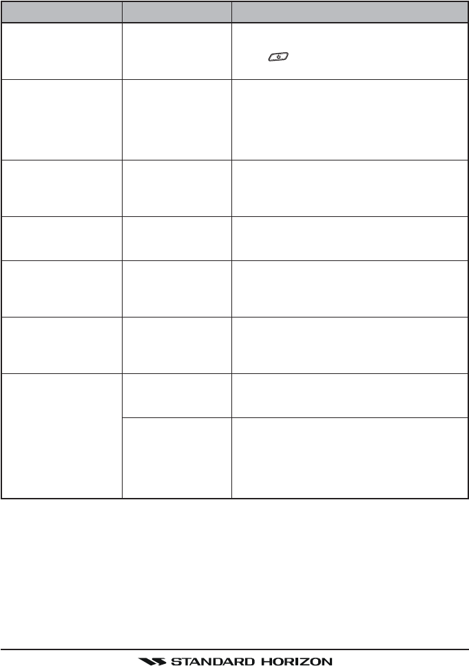
SYMPTOM
Transceiver fails to
power up.
Transceiver blows fuse
when connected to
power supply.
Popping or whining
noise from the speaker
while engine runs.
Sound is not emitted
from the internal or ex-
ternal speaker.
Receiving station re-
ports low transmit
power, even with trans-
ceiver set to HI power.
“HI BATTERY” or “LO
BATTERY” message
appears when the
power is turned on.
Your position is not dis-
played.
PROBABLE CAUSE
No DC voltage to the
transceiver, or blown
fuse.
Reversed power
wires.
Engine noise.
Accessory cable.
Antenna.
The power supply
voltage is too high or
too low.
Accessory cable.
Setting of the GPS
navigation receiver.
REMEDY
a. Check the 12VDC battery connections and
the fuse.
b. The key needs to be pressed and held to
turn the radio on.
Check the power cable for DC voltage, or re-
place the fuse (6A 250V).
Make sure the red wire is connected to the posi-
tive (+) battery post, and the black wire is con-
nected to the negative (–) battery post. If the
fuse still blows, contact your Dealer.
Reroute the DC power cables away from the
engine. Add noise suppressor on power cable.
Change to resistive spark plug wires and/or add
an alternator whine filter.
Check the connections of the accessory cable
(Short Circuit the External speaker cable
WHITE/SHIELD).
Have the antenna checked or test the trans-
ceiver with another antenna. If the problem per-
sists, contact your Dealer for servicing.
Confirm that the connected power supply volt-
age is not 17 volts or lower than 10 volts.
Check the accessory cable connection.
Some GPS use the battery ground line for NMEA
connection.
Check the output signal format of the GPS navi-
gation receiver. This radio requires NMEA0183
format with GLL, RMB, or RMC sentence as an
output signal. If the GPS has a baud rate set-
ting make sure to select 4800 and parity to
NONE.
An “RA” Return Authorization number is not necessary to send a product in for
service. Include a brief note describing the problem along with your name,
return address, phone number, and proof of purchase.
18.3 TROUBLESHOOTING CHART
FCC ID:K6630483X3D / IC:511B-30483X3S
Vertex Standard Co., Ltd.

GX1600Page 102
19 CHANNEL ASSIGNMENTS
Tables on the following columns list the VHF Marine Channel assignments for
U.S.A. and International use. Below are listed some data about the charts.
1. VTS. Where indicated, these channels are part of the U.S. Coast Guard’s
Vessel Traffic System.
2. Alpha channel numbers, that is, channel numbers followed by the letter A
(such as Channel 07A) are simplex channels on the U.S.A. or Canadian
channel assignments whose counterparts in the International assignments
are duplex channels. International channels do not use “alpha” numbers.
If you call the Coast Guard on Channel 16, they will sometimes ask you to
“go to channel 22 Alpha.” This is a channel assigned to U.S.A, and Cana-
dian Coast Guards for handling distress and other calls. If your radio is set
for International operation you will go to Channel 22 instead of 22A, and
will not be able to communicate with the Coast Guard. To use Channel
22A, your radio must be set for USA or Canada operation, usually by a U/
I/C (USA/International/Canada) control or combination of controls. Chan-
nel 22 (without an “A”) is an International duplex channel for port opera-
tions. Some radios indicate an “A” adjacent to the alpha channels on the
display; on others “alpha” is not indicated but the proper channel is se-
lected based on the U/I/C setting.
3. Bridge-to-Bridge channels (for example, Channel 13) are for use by bridge
operators on inter-coastal waterways and rivers. It is also used by marine
vessels in the vicinity of these bridges for navigation and for communicat-
ing with the bridge operators. Note that a limit of 1 Watt is specified for
these channels.
4. The S/D column on the chart indicates either S (simplex) or D (duplex).
Simplex means transmitting and receiving on the same frequency. Only
one party at a time can talk, unlike a telephone. Be sure to say “over” and
release your microphone push-to-talk switch at the end of each transmis-
sion. Duplex operation involves the use of one frequency for transmitting
and a separate frequency for receiving. On channels specified as duplex
on the charts, correct mode of operation is established automatically by
your radio when you select a channel; you cannot change the mode. And
you still must release the push-to-talk switch after each transmission in
order to listen to the radio.
5. Channels normally used by recreational boaters are those that include the
term “non-commercial” in the Channel Use column of the chart. Some of
these are shared with other users and some are used only in certain geo-
graphic regions.
FCC ID:K6630483X3D / IC:511B-30483X3S
Vertex Standard Co., Ltd.

Page 103GX1600
6. Marine vessels equipped with VHF radios are required to monitor Channel
16.
7. 156.050 MHz and 156.175 MHz are available for port operations and com-
mercial communications purposes when used only within the U.S. Coast
Guard designated Vessel Traffic Services (VTS) area of New Orleans, on
the lower Mississippi River from the various pass entrances in the Gulf of
Mexico to Devil’s Swamp Light at River Mile 242.4 above head of passes
near Baton Rouge.
8. 156.250 MHz is available for port operations communications use only
within the U.S. Coast Guard designated VTS radio protection areas of
New Orleans and Houston described in Sec. 80.383. 156.250 MHz is avail-
able for intership port operations communications used only within the area
of Los Angeles and Long Beach harbors, within a 25- nautical mile radius
of Point Fermin, California.
9. 156.550 MHz, 156.600 MHz and 156.700 MHz are available in the U.S.
Coast Guard designated port areas only for VTS communications and in
the Great Lakes available primarily for communications relating to the move-
ment of ships in sectors designated by the St. Lawrence Seaway Develop-
ment Corporation or the U.S. Coast Guard. The use of these frequencies
outside VTS and ship movement sector protected areas is permitted pro-
vided they cause no interference to VTS and ship movement communica-
tions in their respective designated sectors.
10. Use of 156.875 MHz is limited to communications with pilots regarding the
movement and docking of ships. Normal output power must not exceed 1
watt. 5: 156.375 MHz and 156.650 MHz are available primarily for intership
navigational communications. These frequencies are available between
coast and ship on a secondary basis when used on or in the vicinity of
locks or drawbridges. Normal output power must not exceed 1 watt. Maxi-
mum output power must not exceed 10 watts for coast stations or 25 watts
for ship stations.
11. On the Great Lakes, in addition to bridge-to-bridge communications,
156.650 MHz is available for vessel control purposes in established vessel
traffic systems. 156.650 MHz is not available for use in the Mississippi
River from South Pass Lighted Whistle Buoy “2” and Southwest Pass en-
trance Mid-channel Lighted Whistle Buoy to mile 242.4 above Head of
Passes near Baton Rouge. Additionally it is not available for use in the
Mississippi River-Gulf Outlet, the Mississippi River-Gulf Outlet Canal, and
the Inner Harbor Navigational Canal, except to aid the transition from these
areas.
FCC ID:K6630483X3D / IC:511B-30483X3S
Vertex Standard Co., Ltd.

GX1600Page 104
12. Use of 156.375 MHz is available for navigational communications only in
the Mississippi River from South Pass Lighted Whistle Buoy “2” and South-
west Pass entrance Mid channel Lighted Whistle Buoy to mile 242.4 above
head of Passes near Baton Rouge, and in addition over the full length of
the Mississippi River-Gulf Outlet Canal from entrance to its junction with
the Inner Harbor Navigation Canal, and over the full length of the Inner
Harbor Navigation Canal from its junction with the Mississippi River to its
entry to Lake Pontchartrain at the New Seabrook vehicular bridge.
13. Within 120 km (75 miles) of the United States/Canada border, in the area
of the Puget Sound and the Strait of Juan de Fuca and its approaches,
157.425 MHz is half of the duplex pair designated as Channel 88. In this
area, Channel 88 is available to ship stations for communications with
public coast stations only. More than 120 km (75 miles) from the United
States/Canada border in the area of the Puget Sound and the Strait of
Juan de Fuca, its approaches, the Great Lakes, and the St. Lawrence
Seaway, 157.425 MHz is available for intership and commercial communi-
cations. Outside Puget Sound area and its approaches and the Great Lakes,
157.425 MHz is also available for communications between commercial
fishing vessels and associated aircraft while engaged in commercial fish-
ing activities.
14. When the frequency 156.850 MHz is authorized, it may be used addition-
ally for search and rescue training exercises conducted by state or local
governments.
15. The frequency 156.850 MHz is additionally available to coast stations on
the Great Lakes for transmission of scheduled Coded Marine Weather
Forecasts (MAFOR), Great Lakes Weather Broadcast (LAWEB) and sched-
uled Notices to Mariners or Bulletins. F3C and J3C emissions are permit-
ted. Coast Stations on the Great Lakes must cease weather broadcasts
which cause interference to stations operating on 156.800 MHz until the
interference problem is resolved.
16. The frequency 157.100 MHz is authorized for search and rescue training
exercises by state or local government in conjunction with U.S. Coast Guard
stations. Prior U.S. Coast Guard approval is required. Use must cease
immediately on U.S. Coast Guard request.
17. The duplex pair for channel 20 (157.000/161.600 MHz) may be used for
ship to coast station communications.
18. Available for assignment to coast stations, the use of which is in accord
with an agreed program, for the broadcast of information to ship stations
concerning the enviro.
FCC ID:K6630483X3D / IC:511B-30483X3S
Vertex Standard Co., Ltd.

Page 105GX1600
VHF MARINE CHANNEL CHART
CH U C I S/D TX RX CHANNEL USE
01 X X D 156.050 160.650 Public Correspondence (Marine Operator)
01A X S 156.050 Port Operation and Commercial.
VTS in selected areas
02 X X D 156.100 160.700 Public Correspondence (Marine Operator)
03 X X D 156.150 160.750 Public Correspondence (Marine Operator)
03A X S 156.150 U.S. Government Only, Coast Guard
04 X D 156.200 160.800 Public Correspondence (Marine Operator),
Port operation, ship movement
04A X S 156.200 Pacific coast: Coast Guard, East Coast:
Commercial fishing
05 X D 156.250 160.850 Public Correspondence (Marine Operator),
Port operation, ship movement
05A X X S 156.250 Port operation. VTS in Seattle
06 X X X S 156.300 Inter-ship Sefety
07 X D 156.350 160.950 Public Correspondence (Marine Operator),
Port operation, ship movement
07A X X S 156.350 Commercial
08 X X X S 156.400 Commercial (Inter-ship only)
09 X X X S 156.450 Boater Calling channel, Commercial &
Non-commercial (Recreational)
10 X X X S 156.500 Commercial
11 X X X S 156.550 Commercial. VTS in selected areas.
12 X X X S 156.600 Port operation. VTS in selected areas.
13 X X X S 156.650 Inter-ship Navigation Safety (Bridge-to-bridge)
14 X X X S 156.700 Port operation. VTS in selected areas.
15 X S - - - 156.750 Environmental (Receive only)
15 X X S 156.750 Commercial, non-commercial, ship movement (1 W)
16 X X X S 156.800 International Distress, Safety and Calling
17 X X X S 156.850 State Controlled (1 W)
18 X D 156.900 161.500 Port operation, ship movement
18A X X S 156.900 Commercial
19 X D 156.950 161.550 Port operation, ship movement
19A X S 156.950 US: Commercial
19A X S 156.950 Coast Guard
20 X X X D 157.000 161.600 Canadian Coast Guard Only,
International: port operations and shipment
20A X S 157.000 Port operation
21 X D 157.050 161.650 Port operation, ship movement
21A X X S 157.050 U.S. Government Only, Canadian Coast Guard
22 X D 157.100 161.700 Port operation, ship movement
22A X X S 157.100 US and Canadian Coast Guard Liaison and
Maritime Safety Information Broadcasts announced
on channel 16
23 X X D 157.150 161.750 Public Correspondence (Marine Operator)
23A X S 157.150 U.S. Government Only
24 X X X D 157.200 161.800 Public Correspondence (Marine Operator)
25 X X X D 157.250 161.850 Public Correspondence (Marine Operator)
26 X X X D 157.300 161.900 Public Correspondence (Marine Operator)
27 X X X D 157.350 161.950 Public Correspondence (Marine Operator)
28 X X X D 157.400 162.000 Public Correspondence (Marine Operator)
FCC ID:K6630483X3D / IC:511B-30483X3S
Vertex Standard Co., Ltd.

GX1600Page 106
VHF MARINE CHANNEL CHART
CH U C I S/D TX RX CHANNEL USE
60 X X D 156.025 160.625 Public Correspondence (Marine Operator)
61 X D 156.075 160.675 Public Correspondence (Marine Operator),
Port operation, ship movement
61A X X S 156.075 Public Coast: Coast Guard;
East Coast: commercial fishing only
62 X D 156.125 160.725 Public Correspondence (Marine Operator),
Port operation, ship movement
62A X S 156.125 Public Coast: Coast Guard;
East Coast: commercial fishing only
63 X D 156.175 160.775 Public Correspondence (Marine Operator),
Port operation, ship movement
63A X X S 156.175 Port Operation and Commercial.
VTS in selected areas.
64 X X D 156.225 160.825 Public Correspondence (Marine Operator),
Port operation, ship movement
64A X X S 156.225 Public Correspondence (Marine Operator),
Port operation, ship movement
65 X D 156.275 160.875 Public Correspondence (Marine Operator),
Port operation, ship movement
65A X X S 156.275 Port Opeations
66 X D 156.325 160.925 Public Correspondence (Marine Operator),
Port operation, ship movement
66A X X S 156.325 Port Operations
67 X X X S 156.375 US: Commercial. Used for Bridge-to-bridge com
muni-cations in lower Mississippi River. Inter-ship
only,
Canada: Commercial fishing, S&R
68 X X X S 156.425 Non-commercial (Recreational)
69 X X X S 156.475 US: Non-commercial (Recreational),
Canada: Commercial fishing only,
International: Inter-ship, Port opertions and Ship
movement
70 X X X S 156.525 Digital selective calling (voice communications not
allowed)
71 X X X S 156.575 US, Canada: Non-commercial (Recreational),
International: Port opertions and Ship movement
72 X X X S 156.625 Non-commercial (Inter-ship only)
73 X X X S 156.675 US: Port Operations,
Canada: Commercial fish ing only,
International: Inter-ship, Port opertions and Ship
movement
74 X X X S 156.725 US: Port Operations,
Canada: Commercial fishing only,
International: Inter-ship, Port opertions and Ship
movement
75 X X X S 156.775 Port Operations (Inter-ship only) (1W)
76 X X X S 156.825 Port Operations (Inter-ship only) (1W)
77 X X S 156.875 Port Operations (Inter-ship only) (1W)
77 X S 156.875 Port Operations (Inter-ship only)
78 X D 156.925 161.525 Public Correspondence (Marine Operator),
Port operation, ship-movement
78A X X S 156.925 Non-commercial (Recreational)
79 X D 156.975 161.575 Port operation and Ship movement
79A X X S 156.975 Commercial
FCC ID:K6630483X3D / IC:511B-30483X3S
Vertex Standard Co., Ltd.
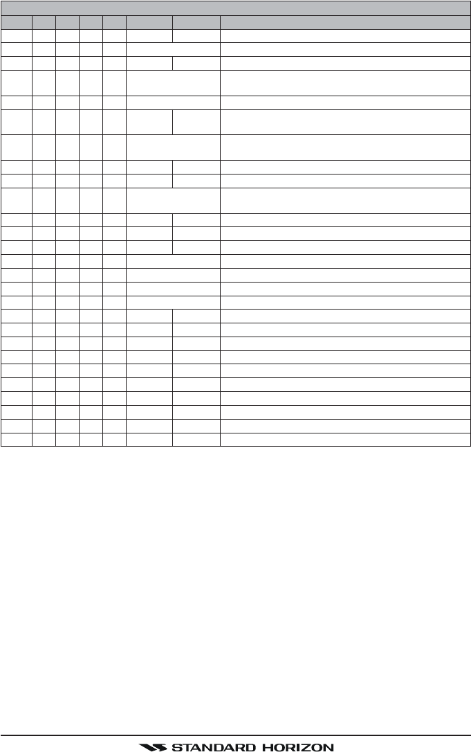
Page 107GX1600
VHF MARINE CHANNEL CHART
CH U C I S/D TX RX CHANNEL USE
80 X D 157.025 161.625 Port operation, ship movement
80A X X S 157.025 Commercial
81 X D 157.075 161.675 Port operation, ship movement
81A X S 157.075 U.S. Government Only -
Environmental protection operations.
81A X S 157.075 Canadian Coast Guard Only
82 X D 157.125 161.725 Public Correspondence (Marine Operator),
Port operation, ship movement
82A X X S 157.125 U.S. Government Only,
Canadian Coast Guard Only
83 X D 157.175 161.775 Canadian Coast Guard Only
83 X D 157.175 161.775 Public Correspondence (Marine Operator)
83A X X S 157.175 U.S. Government Only,
Canadian Coast Guard Only
84 X X X D 157.225 161.825 Public Correspondence (Marine Operator)
85 X X X D 157.275 161.875 Public Correspondence (Marine Operator)
86 X X X D 157.325 161.925 Public Correspondence (Marine Operator)
87 X X S 157.375 Port operation, ship movement
87A X S 157.375 Public Correspondence (Marine Operator)
88 X X S 157.425 Port operation, ship movement
88A X S 157.425 Commercial, Inter-ship Only
WX01
X X X D - - - 162.550 Weather (receive only)
WX02
X X X D - - - 162.400 Weather (receive only)
WX03
X X X D - - - 162.475 Weather (receive only)
WX04
X X X D - - - 162.425 Weather (receive only)
WX05
X X X D - - - 162.450 Weather (receive only)
WX06
X X X D - - - 162.500 Weather (receive only)
WX07
X X X D - - - 162.525 Weather (receive only)
WX08
X X X D - - - 161.650 Weather (receive only)
WX09
X X X D - - - 161.775 Weather (receive only)
WX10
X X X D - - - 163.275 Weather (receive only)
NOTE: Simplex channels, 3A, 21A, 23A, 61A, 64A, 81A, 82A and 83A CANNOT be lawfully used
by the general public in U.S.A. waters.
FCC ID:K6630483X3D / IC:511B-30483X3S
Vertex Standard Co., Ltd.

GX1600Page 108
20 WARRANTY
Marine Products Limited Warranty
PLEASE NOTE
The following “Limited Warranty” is for valid for products that have been
purchased in the United States and Canada. For limited Warranty details
outside the United States, contact the dealer in your country.
STANDARD HORIZON (a division of VERTEX STANDARD) warrants, to the
original purchaser only, each new Marine Communications Product (“Prod-
uct”) manufactured and/or supplied by STANDARD HORIZON against defects
in materials and workmanship under normal use and service for a period of
time from the date of purchase as follows:
Fixed Mount and Portable Transceivers
1 year - if purchased before 01/01/91
3 years - if purchased between 01/01/91 and 01/01/94
3 years Waterproof - if purchased after 01/01/94
Loud hailers
1 year - if purchased before 01/01/91
3 years - if purchased after 01/01/91
Associated Chargers
1 year - if purchased before 01/01/91
3 years - if purchased after 01/01/91
Associated Batteries - 18 months. Note: Batteries will be deemed deflective
only if storage capacity drops below 80% of rated capacity or if leakage develops.
Associated Accessories - 1 year. Includes: Microphones/Handsets, External
Speakers, Antennas, Carrying Accessories, Power Supplies, and Signaling Boards.
To receive warranty service, the purchaser must deliver the Product, transpor-
tation and insurance prepaid, to STANDARD HORIZON (a division of VER-
TEX STANDARD), Attention Marine repairs 10900 Walker Street, Cypress, CA
90630. Include proof of purchase indicating model. serial number, and date of
purchase. STANDARD HORIZON will return the Product to the purchaser freight
prepaid. Products purchased prior to January 1, 1991 will bear the STAN-
DARD HORIZON warranty terms in effect prior to that date.
In the event of a defect, malfunction or failure of the Product during the war-
ranty period, STANDARD HORIZON’s liability for any breach of contract or
any breach of express or implied warranties in connection with the sale of
Products shall be limited solely to repair or replacement, at its option, of the
Product or part(s) therein which, upon examination by STANDARD HORIZON,
FCC ID:K6630483X3D / IC:511B-30483X3S
Vertex Standard Co., Ltd.

Page 109GX1600
appear to be defective or not up to factory specifications. STANDARD HORI-
ZON may, at its option, repair or replace parts or subassemblies with new or
reconditioned parts and subassemblies. Parts thus repaired or replaced are
warranted for the balance of the original applicable warranty.
STANDARD HORIZON will not warrant installation, maintenance or service of
the Products. In all instances, STANDARD HORIZON’s liability for damages
shall not exceed the purchase price of the defective Product.
This warranty only extends to Products sold within the 50 States of the United
States of America and the District of Columbia.
STANDARD HORIZON will pay all labor to repair the product and replacement
parts charges incurred in providing the warranty service except where pur-
chaser abuse or other qualifying exceptions exist. The purchaser must pay
any transportation expenses incurred in returning the Product to STANDARD
HORIZON for service.
This limited warranty does not extend to any Product which has been sub-
jected to misuse, neglect, accident, incorrect wiring by anyone other than STAN-
DARD HORIZON, improper installation, or subjected to use in violation of in-
structions furnished by STANDARD HORIZON, nor does this warranty extend
to Products on which the serial number has been removed, defaced, or changed.
STANDARD HORIZON cannot be responsible in any way for ancillary equip-
ment not furnished by STANDARD HORIZON which is attached to or used in
connection with STANDARD HORIZON’s Products, or for the operation of the
Product with any ancillary equipment, and all such equipment is expressly
excluded from this warranty. STANDARD HORIZON disclaims liability for range,
coverage, or operation of the Product and ancillary equipment as a whole
under this warranty. STANDARD HORIZON reserves the right to make changes
or improvements in Products, during subsequent production, without incurring
the obligation to install such changes or improvements on previously manu-
factured Products.
The implied warranties which the law imposes on the sale of this Product are
expressly LIMITED, in duration, to the time period specified above. STAN-
DARD HORIZON shall not be liable under any circumstances for consequen-
tial damages resulting from the use and operation of this Product, or from the
breach of this LIMITED WARRANTY, any implied warranties, or any contract
with STANDARD HORIZON. IN CONNECTION WITH THE SALE OF ITS
PRODUCTS, STANDARD HORIZON MAKES NO WARRANTIES, EXPRESS
OR IMPLIED AS TO THE MERCHANTABILITY OR FITNESS FOR A PAR-
TICULAR PURPOSE OR OTHERWISE, EXCEPT AS EXPRESSLY SET
FORTH HEREIN.
FCC ID:K6630483X3D / IC:511B-30483X3S
Vertex Standard Co., Ltd.

GX1600Page 110
Some states do not allow the exclusion or limitation of incidental or conse-
quential damages, or limitation on how long an implied warranty lasts, so the
above limitations or exclusions may not apply. This warranty gives specific
legal rights, and there may be other rights which may vary from state to state.
ONLY PRODUCTS SOLD ON OR AFTER JANUARY 1, 1991 ARE COVERED
UNDER THE TERMS OF THIS LIMITED WARRANTY.
ON-LINE WARRANTY REGISTRATION
THANK YOU for buying STANDARD HORIZON (a division of Vertex
Standard) products! We are confident your new radio will serve your
needs for many years!
Please visit www.standardhorizon.com to register your Marine
VHF. It should be noted that visiting the Web site from time to time may
be beneficial to you, as new products are released they will appear on
the STANDARD HORIZON Web site. Also a statement regarding prod-
uct support should be added to the manual.
Product Support Inquiries
If you have any questions or comments regarding the use of the radio,
you can visit the STANDARD HORIZON Web site to send an E-Mail or
contact the Product Support team at (714) 827-7600 ext 6300 M-F 7:00-
5:00PST.
In addition to the warranty, STANDARD HORIZON includes a lifetime “flat
rate” and “customer loyalty” programs to provide service after the warranty
period has expired. If you wish to obtain the flat rate price for out-of-war-
ranty repair, you must include the information on the Owner’s Record with
the unit when you return it to your Dealer or to STANDARD HORIZON.
Lifetime Flat Rate Service Program: For the original Owner only, for the
lifetime of the unit, STANDARD HORIZON will repair the unit to original
specifications.
Note: The flat rate amount is payable by the Owner only if STANDARD
HORIZON or the STANDARD HORIZON Dealer determines that a re-
pair is needed. After the repair, a 90-day warranty will be in effect from
the date of return of the unit to the Owner.
This service program is not available for equipment which has failed as
a result of neglect, accident, breakage, misuse, improper installation or
modification, or water damage (depending on the product).
FCC ID:K6630483X3D / IC:511B-30483X3S
Vertex Standard Co., Ltd.

Page 111GX1600
21 RESET PROCEDURES
21.1 MEMORY CLEAR
To clear the Scan memory and Preset memory:
1. Turn the radio off.
2. Press and hold in the three [Programmable] keys while turning the radio
on.
21.2 MICROPROCESSOR RESETTING
To clear all memories and other settings to factory defaults (except the Chan-
nel Group, MMSI number, and DSC directory information):
1. Turn the radio off.
2. Press and hold in the and keys while turning the radio on.
FCC ID:K6630483X3D / IC:511B-30483X3S
Vertex Standard Co., Ltd.

GX1600Page 112
22 SPECIFICATIONS
Performance specifications are nominal, unless otherwise indicated, and are
subject to change without notice.
22.1 GENERAL
Channels ............................................... All USA, International and Canadian
Normal Input Voltage ..................................................................... 13.8 V DC
Operating Voltage Range ......................................................... 11 V to 16.5 V
Current Drain
Standby ........................................................................................... 0.45 A
Receiver (at Maximum AF Output) ..................................................... 0.8 A
Transmit ..................................................................... 5.0 A (Hi), 1.0 A (Lo)
Operating Temperature Range ............... –4 °F to +140 °F (–20 °C to +60 °C)
Distress Call Log ......................................................................................... 27
Individual Call Log ....................................................................................... 64
Individual Call Directory............................................................................... 80
Group Call Directory .................................................................................... 32
Waypoint Directory .................................................................................... 100
Display Type ...... 2.75” x 1.33” (70 x 34 mm) Full Dot Matrix (132 x 64 pixels)
Dimensions (WxHxD) ...................... 5.90” x 3.35” x 3.54” (150 x 85 x 90 mm)
Flush-Mount Dimensions (WxHxD) . 5.39” x 2.84” x 3.54” (137 x 72 x 90 mm)
Weight ................................................................................... 1.98 lbs (0.9 kg)
22.2 TRANSMITTER
Frequency Range ............................................ 156.025 MHz to 157.425 MHz
RF Output Power ............................................................. 25 W (Hi), 1 W (Lo)
Conducted Spurious Emissions ........... Less than –80 dBc (Hi), –66 dBc (Lo)
Audio Response .......................................... within +1/–3dB of a 6 dB/Octave
pre-enphasis characteristic at 300 to 3000 Hz
Audio Distortion ........................................................................ Less than 5 %
Modulation .................................... 16K0G3E (for Voice), 16K0G2B (for DSC)
Frequency Stability .......................................... ±0.0003 % (–20 °C to +60 °C)
FM Hum and Noise ............................................................................... 50 dB
FCC ID:K6630483X3D / IC:511B-30483X3S
Vertex Standard Co., Ltd.

Page 113GX1600
22.3 RECEIVER (for Voice and DSC)
Frequency Range ............................................ 156.050 MHz to 163.275 MHz
Sensitivity
20 dB Quieting .............................................................................. 0.35 μV
12 dB SINAD ................................................................................. 0.25 μV
Squelch Sensitivity (Threshold) ..................................................... 0.13 μV
Modulation Acceptance Bandwidth ...................................................±7.5 kHz
Selectivity (Typical)
Spurious and Image Rejection ................ 80 dB for Voice (75 dB for DSC)
Intermodulation and Rejection ................ 70 dB for Voice (70 dB for DSC)
Audio Output ................................ 4.5 W (at 4 ohms external speaker output)
Audio Response .......................................... within +1/–3dB of a 6 dB/Octave
de-enphasis characteristic at 300 to 3000 Hz
Frequency Stability ............. ±0.0003 % (–4 °F to +140 °F [–20 °C to +60 °C])
Channel Spacing ................................................................................. 25 kHz
DSC Format .......................................................................... ITU-R M.493-12
Antenuator (Local) .................................................................... Approx. 10 dB
22.4 NMEA Input/Output
NMEA 0183 GPS Input (4800 baud) .......................... GGA, GLL, GNS, RMC
NMEA 0183 DSC Output (4800 baud) ..................................... DSC and DSE
FCC ID:K6630483X3D / IC:511B-30483X3S
Vertex Standard Co., Ltd.

GX1600Page 114
22.6 DIMENSIONS
FCC ID:K6630483X3D / IC:511B-30483X3S
Vertex Standard Co., Ltd.

Page 115GX1600
MEMO
FCC ID:K6630483X3D / IC:511B-30483X3S
Vertex Standard Co., Ltd.

GX1600Page 116
MEMO
FCC ID:K6630483X3D / IC:511B-30483X3S
Vertex Standard Co., Ltd.

Page 117GX1600
This device complies with part 15 of the FCC rules. Operation is subject
to the condition that this device does not cause harmful interference.
Part 15.21: Changes or modifications to this device not expressly ap-
proved by Vertex Standard could void the User’s authorization to oper-
ate this device.
FCC ID:K6630483X3D / IC:511B-30483X3S
Vertex Standard Co., Ltd.

GX1600Page 118
Copyright 2010
VERTEX STANDARD CO., LTD.
All rights reserved.
No portion of this manual
may be reproduced
without the permission of
VERTEX STANDARD CO., LTD.
Marine Division of VERTEX STANDARD
US Headquarters
10900 Walker Street, Cypress, CA 90630, U.S.A.
www.standardhorizon.com
EM044N102
FCC ID:K6630483X3D / IC:511B-30483X3S
Vertex Standard Co., Ltd.