Yaesu Musen 50013X20 PORTABLE AIRBAND TRANSCEIVER User Manual FTA 750 FTA 550 FTA 450 Operating Manual
Yaesu Musen Co., Ltd. PORTABLE AIRBAND TRANSCEIVER FTA 750 FTA 550 FTA 450 Operating Manual
Contents
- 1. Operational Manual
- 2. Operating Manual 1
Operating Manual 1
Operating Manual
AIR BAND TRANSCEIVER
FTA-750
FTA-550
FTA-450
FCC ID: K6650013X20
IC: 511B-50013X20

Contents
Important Notice! .......................................................... 1
Introduction ................................................................... 2
Models, Accessories and Options .............................. 3
Models ............................................................................... 3
Supplied Accessories ......................................................... 3
Available Options .............................................................. 3
Controls & Connectors ................................................ 4
LCD Display .................................................................. 8
Before You Begin ........................................................ 12
Battery Installation and Removal .................................... 12
Battery Charging .............................................................. 13
Alkaline Battery Tray Installation ................................... 14
Low Battery Indication .................................................... 14
External DC Power Supply Connection .......................... 15
Antenna Installation ......................................................... 15
Belt Clip Installation ........................................................ 16
Headset Connection ......................................................... 16
Precautions ....................................................................... 17
Basic Operation .......................................................... 18
Reception (COM Band) ................................................... 18
Accessing the 121.5 MHz Emergency Frequency ........... 21
Transmission (COM Band) .............................................. 22
Operation Bands .............................................................. 23
Operation Modes ............................................................. 24
Resetting the Radio .......................................................... 25
Advanced Operation .................................................. 27
Reception of VOR Signals (except for FTA-450) ........... 27
Reception of ILS Signals (except for FTA-450) .............. 31
Split Operation ................................................................. 33
Reception of Weather Channel Broadcasts ...................... 35
Dual Watch Operation ..................................................... 37
Timer Mode Operation .................................................... 39
TOT Feature ..................................................................... 43
Saving the Battery during Reception ............................... 43
Using the Headset Microphone ....................................... 44
VOX Operation ................................................................ 44
Side Tone Control ............................................................ 45
Lock Function .................................................................. 46
PTT Lock Function .......................................................... 48
Changing the Channel Steps ............................................ 48
ANL Feature .................................................................... 49
Memory Operation ...................................................... 50
Recalling the Memories ................................................... 50
Instant Storage ................................................................. 52
Maintenance of the Memory ............................................ 53
Scanning Operation ................................................... 57
Scanning Channels .......................................................... 57
Selecting Scanning Band ................................................. 58
Scanning the Specied Channels ..................................... 59
GPS Function (FTA-750 Only) ................................... 61
Activating the GPS Unit .................................................. 61
Displaying the Position Information ................................ 62
Memorizing the Position Information ............................. 64
Recording the Position Information ................................ 65
Waypoint Navigation (FTA-750 Only) ........................ 66
Entering the Navigation (NAVI) Mode ........................... 66
Setting the Destination ..................................................... 67
Setup Mode ................................................................. 70
Basic Operation ............................................................... 70
Maintenance of the Memory ............................................ 71
Setting of the COMM Mode Operation ........................... 72
Setting of the GPS Mode Operation (FTA-750 Only) ..... 75
Setting of the Operation and Conguration of the Radio 80
About the Radio ............................................................... 82
Summary of the SETUP Menu ........................................ 83
Specications ............................................................. 85
Troubleshooting for Headset Connection ................ 87
FCC ID: K6650013X20
IC: 511B-50013X20

FTA-750/FTA-550/FTA-450 OperATing MAnuAl 1
Important notIce!
FCC RF Exposure Compliance Requirements for Occupational Use Only:
The FTA-750/FTA-550/FTA-450 have been tested and comply with the Federal Communications Commission (FCC)
RF exposure limits for Occupational Use/Controlled Exposure Environment. In addition, both radios comply with the
following Standards and Guidelines:
FCC 96-326, Guidelines for Evaluating the Environmental Effects of Radio-Frequency Radiation.
FCC OET Bulletin 65 Edition 97-01 (1997) Supplement C, Evaluating Compliance with FCC Guidelines for Hu-
man Exposure to Radio Frequency Electromagnetic Fields.
ANSI/IEEE C95.1-1992, IEEE Standard for Safety Levels with Respect to Human Exposure to Radio Frequency
Electromagnetic Fields, 3 kHz to 300 GHz.
ANSI/IEEE C95.3-1992, IEEE Recommended Practice for the Measurement of Potentially Hazardous Electromag-
netic Fields - RF and Microwave.
This radio is NOT approved for use by the general population in an uncontrolled environment. This radio is
restricted to occupational use, work related operations only where the radio operator must have the knowl-
edge to control its RF exposure conditions.
When transmitting, hold the radio in a vertical position with its microphone 1 to 2 inches (2.5 to 5 cm) away
from your mouth and keep the antenna at least 1 inch (2.5 cm) away from your head and body.
The radio must be used with a maximum operating duty cycle not exceeding 50%, in typical Push-to-Talk
congurations. DO NOT transmit for more than 50% of total radio use time (50% duty cycle). Transmitting
more than 50% of the time can cause FCC RF exposure compliance requirements to be exceeded.
The radio is transmitting when the “TX” icon is displayed on the upper left corner of the screen of the radio.
You can cause the radio to transmit by pressing the PTT button.
Always use YAESU authorized accessories.
NOTICE
There are no user-serviceable points inside this transceiver.
All service jobs must be referred to your Authorized Service Center.
FCC ID: K6650013X20
IC: 511B-50013X20

FTA-750/FTA-550/FTA-450 OperATing MAnuAl
2
IntroductIon
The YAESU FTA-750/FTA-550/FTA-450 are compact, stylish, solid hand-held transceivers providing communica-
tion (transmit and receive) capability on the International Aircraft Communication Band (“COM” band: 118 to 136.975
MHz), and they additionally provide VOR and ILS navigation features on the “NAV” band (108 to 117.975 MHz).
The FTA-750/FTA-550/FTA-450 boast a 1.7” x 1.7” (43.2 x 43.2 mm) full dot matrix LCD displaying a plenty of in-
formation in a row. The FTA-750/FTA-550/FTA-450 include NOAA weather band monitoring and 200 memory chan-
nels. The channel congurations can be easily reprogrammed in minutes using the optional PC Programming Software
and your PC. In addition, the FTA-750 provides positioning and navigation features realized by the internal GPS unit.
We recommend that you read this manual in its entirety, so as to understand the many features of the FTA-750/FTA-
550/FTA-450 completely. Keep this manual handy, so you may use it for reference.
Note: The VOR, ILS, and GPS navigation features of the FTA-750/FTA-550 are for supplemental aids to naviga-
tion only, and are not intended to be a substitute for accurate (primary) VOR or landing service equipment.
You assume full responsibility for the use of the FTA-750/FTA-550.
Congratulations!
You now have at your ngertips a valuable communications tool, a YAESU two-way radio! Rugged, reliable
and easy to use, your YAESU radio will keep you in constant touch with your friends and colleagues for years to
come, with negligible maintenance or down-time.
Please take a few minutes to read this manual carefully. The information presented here will allow you to derive
maximum performance from your radio, in case questions arise later on.
We’re glad you joined the YAESU team. YAESU products cover the entire spectrum of radio communications
applications, and our worldwide support network is here to serve you. Let us help you get your message across.
FCC ID: K6650013X20
IC: 511B-50013X20

FTA-750/FTA-550/FTA-450 OperATing MAnuAl 3
models, accessorIes and optIons
Models
FTA-750L Lithium-ion battery pack included
FTA-550L Lithium-ion battery pack included
FTA-450L Lithium-ion battery pack included
FTA-550 AA Battery Version
Rechargeable battery pack not included.
Requires “AA” batteries for operation.
Supplied Accessories
Lithium-ion Battery Pack (7.4V) SBR-12LI*1
AC Charger SAD-11*1
Charger Cradle SBH-11*1
Cigarette Lighter DC/DC Converter SDD-12
Helical Antenna SRA-13A*2
Belt Clip SHB-11
Headset Adapter Cable SCU-15
Alkaline Battery Tray SBT-12
USB Cable T9101606
Ferrite Core L9190192
Operating Manual
Warranty Card
*1 These accessories are not supplied with the
FTA-550 AA Battery Version.
*2 Antenna gain: 2.15 dBi
Impedance: 50 ohms
Available Options
SSM-10A Speaker Microphone
SEP-10A Earphone (available only with the SSM-
10A)
YCE01 PC Programming Software
(Download the YCE01 PC Programming
Software from the YAESU website.)
Availability of accessories may vary. Some accessories
are supplied as standard per local requirements, while
others may be unavailable in some regions. Consult
your YAESU Dealer for details regarding these and any
newly-available options.
Connection of any non-YAESU-approved accessory,
should it cause damage, may void the Limited Warranty
on this apparatus.
FCC ID: K6650013X20
IC: 511B-50013X20
FTA-750/FTA-550/FTA-450 OperATing MAnuAl
4
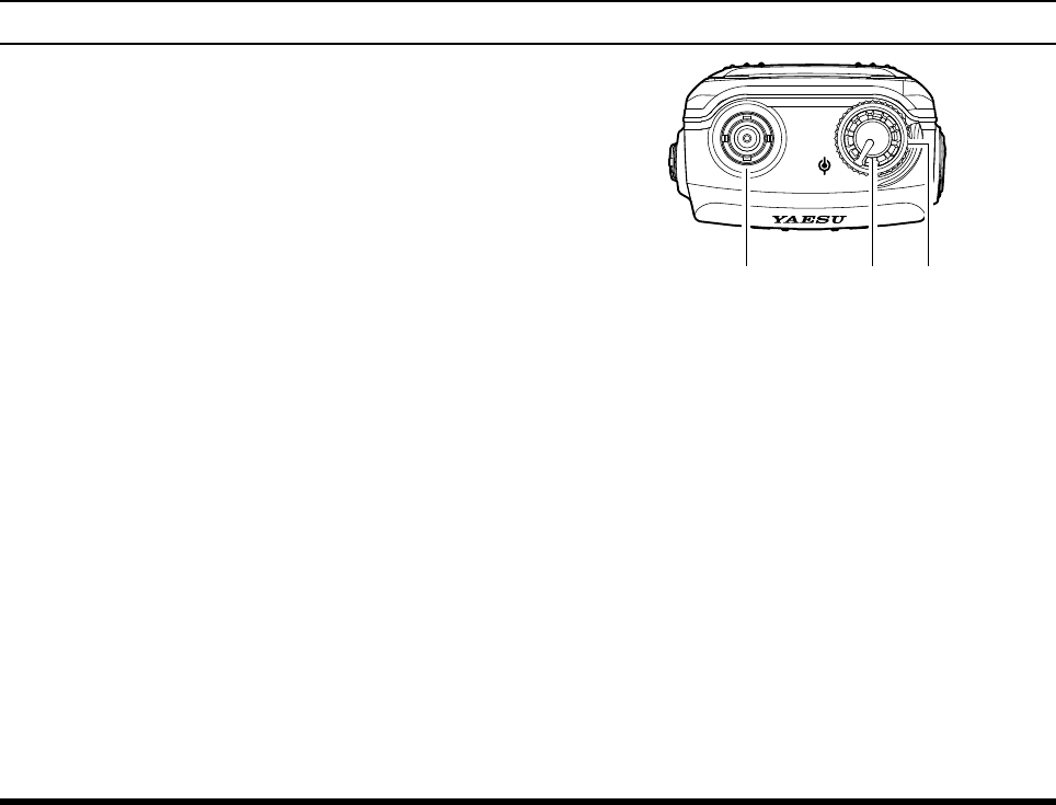
controls & connectors (top panel)
Antenna Jack
This BNC connector accepts the supplied flexible
antenna, or an external antenna designed to provide
50 Ω impedance on the Aircraft Communication
Band.
VOLUME (Inner) Knob
Turn this (inner) control clockwise to increase the
volume.
DIAL Selector (Outer) Knob
This (outer) 20-position detented rotary switch tunes
the operating frequency or selects the memory chan-
nels.
DIAL
VOL
FCC ID: K6650013X20
IC: 511B-50013X20
FTA-750/FTA-550/FTA-450 OperATing MAnuAl 5
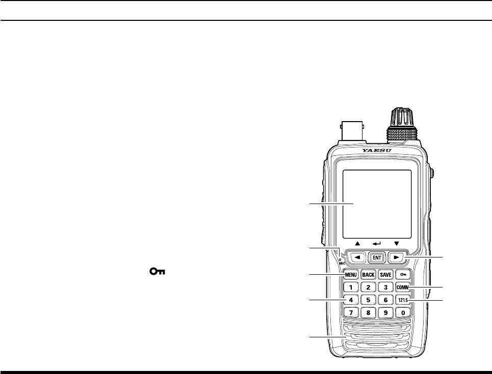
LCD (Liquid Crystal Display)
The display shows selected operating conditions, as
indicated on Pages 8 to 11.
Microphone
Speak into this opening in a normal voice level,
while pressing the PTT switch, to transmit.
Cursor Keys and ENT Key
The cursor keys [◄] and [►] are used to select an
item displayed on the LCD.
Press the ENT key to determine the selection or
entered values.
Control Keys
Press the MENU key to display the MENU screen.
Press the BACK key to return the display to the
previous screen.
Press the SAVE key to store the current channel
information to the memory.
Press and hold the lock key [ ] to enable the
lock feature. Controls and keys will be disabled.
Press and hold again to disable the lock feature.
COMM Key
Press this key to enter the COMM mode instantly.
Numeric Keypad
The keypad is used when setting frequencies.
121.5 Key
Press and hold this key to access the emergency
frequency (121.5 MHz) instantly.
Loudspeaker
The internal speaker is located in this position.
controls & connectors (Front panel)
FCC ID: K6650013X20
IC: 511B-50013X20
FTA-750/FTA-550/FTA-450 OperATing MAnuAl
6
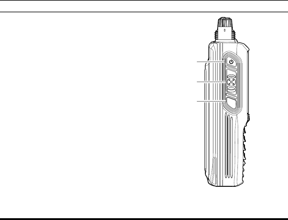
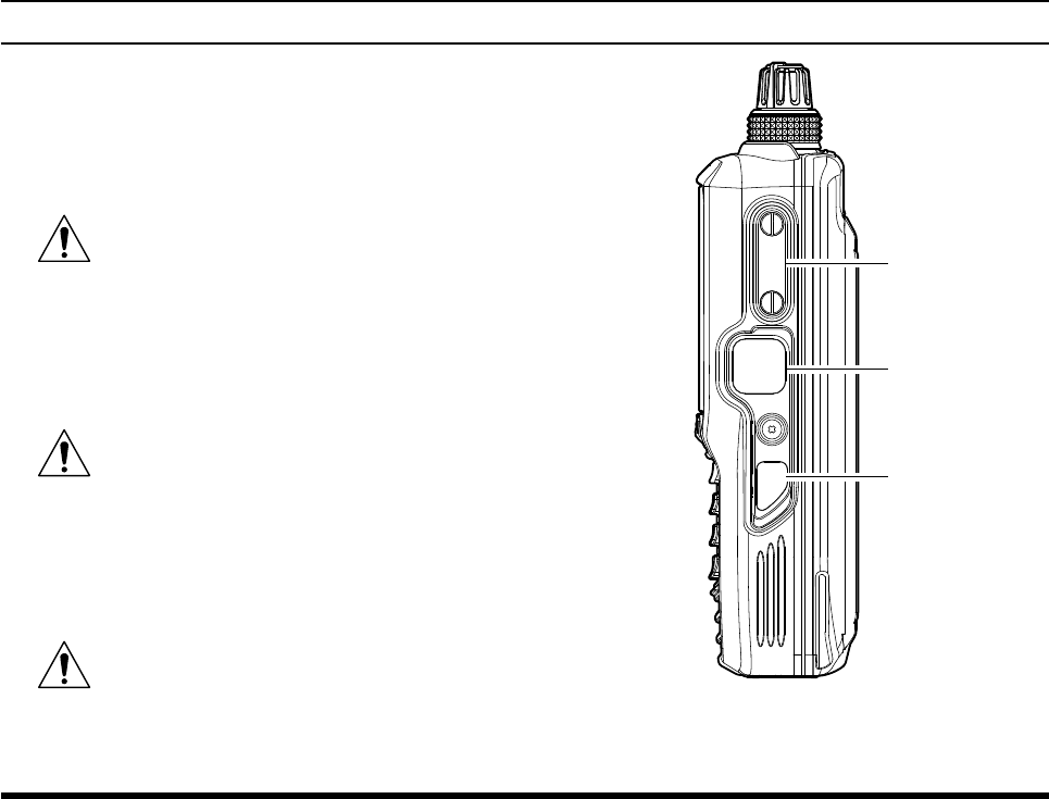
POWER Switch
Press and hold this button to turn the radio on and
off.
PTT (Push To Talk) Switch
Press and hold this button to transmit when you are
operating in the COM band. Release this button to
return to the “Receive” mode. See Page 22 for de-
tails.
SQL (Squelch) Switch
This button may be pressed to “open” the squelch
manually, allowing you to listen for very weak
signals. Press and hold this button for 2 seconds
to “open” the squelch continuously. Press this but-
ton again to resume normal (quiet) monitoring. See
Page 20 for details.
controls & connectors (leFt sIde)
DATA
MIC/SP
EXT
DC
PTT
SQL
FCC ID: K6650013X20
IC: 511B-50013X20
FTA-750/FTA-550/FTA-450 OperATing MAnuAl 7
MIC/SP Jack
You may connect the supplied SCU-15 Headset
Adapter Cable or the optional SSM-10A Speaker/
Microphone to this jack. To use this jack, you must
rst remove the cover from the transceiver body.
Do not allow the FTA-750/FTA-550/FTA-
450 to get wet while the cover over the
MIC/SP jack is removed.
DATA Jack
You may connect the optional USB cable to this
jack. To use this jack, you must rst lift the rubber
cover away from the transceiver body.
Do not allow the FTA-750/FTA-550/-
FTA-450 to get wet while the rubber cover
is removed.
EXT DC Jack
When an external 9.5- to 10.5-Volt DC power
source is available, you may connect the SDD-12
Cigarette Lighter DC/DC Converter here.
1) Do not allow the FTA-750/FTA-550/
FTA-450 to get wet while the rubber cover
is removed.
2) Do not connect any accessory unapproved by
YAESU to supply DC power.
controls & connectors (rIght sIde)
DATA
MIC/SP
EXT
DC
PTT
SQL
FCC ID: K6650013X20
IC: 511B-50013X20
FTA-750/FTA-550/FTA-450 OperATing MAnuAl
8
lcd dIsplay (com Band)
VOL
BUSY
MEM
VDW ±
FLG
MR
G
133.800
132.400
134.800 MIAMI
127.600 MIAMI 2
119.150
124.250 North
129.200
Los Angeles
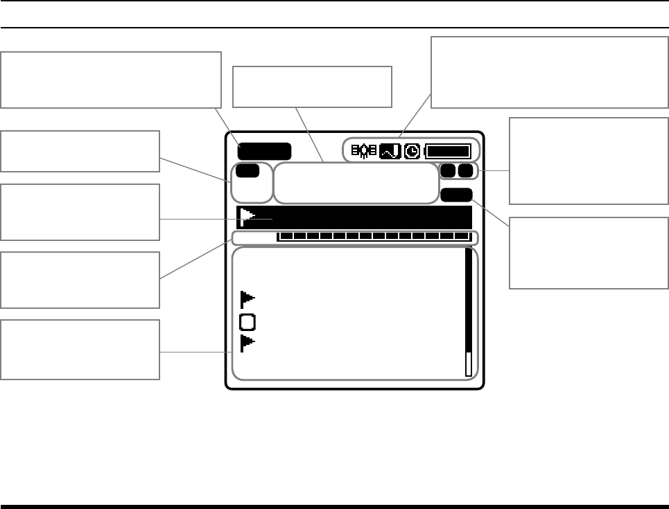
“BUSY” icon appears during
audio reception, or “TX” during
transmission.
This field displays the icons indicating
various statuses of the transceiver, such
as “GPS on”, “Data Logger on”, “Timer
on”, “Battery full”, etc.
This field displays the
operation modes.
This field displays the
operating frequency.
“MEM” icon appears if
the selected channel is
programmed into the Scan
Memory.
This field displays the
icons indicating various
statuses of functions,
such as “VOX on”, “Split
on”, etc.
This field displays the
tag name of the current
channel.
This field displays the
level of the audio volume
or the squelch.
This field displays the
channels you have
previously used.
FCC ID: K6650013X20
IC: 511B-50013X20
FTA-750/FTA-550/FTA-450 OperATing MAnuAl 9
lcd dIsplay (naV Band: except For Fta-450)
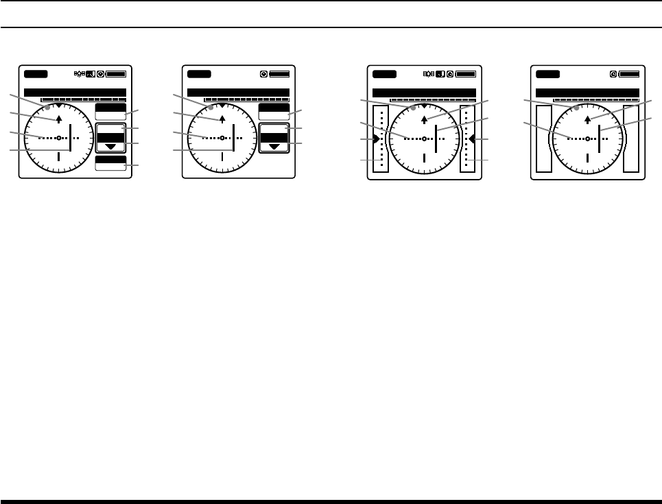
Vor cdI screen
113.600
VOL
SOGKT
150
355°
OBS
000°
NAV VOR
FROM
KLAX-VOR
N
S
EW
33
24
21 15
12
30
3
6
113.600
VOL
355°
OBS
000°
NAV VOR
FROM
KLAX-VOR
N
S
EW
33
24
21 15
12
30
3
6
FTA-750 FTA-550
Compass rose
Course indicator (OBS direction)
Deviation marks
Course deviation needle
OBS (omni bearing selector) value
VOR value
TO/FROM indicator
SOG (speed over ground) value according to the
GPS signal
Ils cdI screen
108.500
VOL
NAV
LOC
GS
KLAX-RWY07R
N
S
EW
33
24
21 15
12
30
3
6
108.500
VOL
NAV
LOC
KLAX-RWY07R
FTA-750 FTA-550
Compass rose
Course (runway) indicator
Deviation marks for localizer
Course deviation needle for localizer
Height deviation indicator for glide slope
Deviation marks for glide slope
FCC ID: K6650013X20
IC: 511B-50013X20
FTA-750/FTA-550/FTA-450 OperATing MAnuAl
10
lcd dIsplay (Fta-750 only)
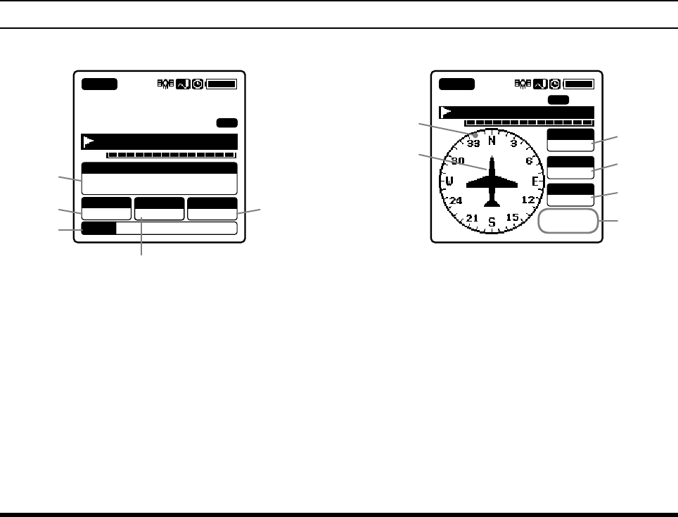
gps InFormatIon screen
133.800
MR
FLG
VOL
LAT/LON
23°
56.890N
123°
56.890W
COG
095°
Oct/25 09:56AM
SOGKT
095 ALTM
0956.8
BUSY
MEM
DATE
KLAX-ATIS
Latitude and longitude values
COG (course over ground) value
Date obtained from the GPS signal
SOG (speed over ground) value
Altitude value
gps compass screen
133.800
VOL
SOGkph
360
Oct/25
09:56AM
COG T
000°
ALTft
10000
BUSY
MR
FLG
KLAX-ATIS
MEM
Compass rose
Course indicator
COG (course over ground) value
SOG (speed over ground) value
Altitude value
Date obtained from the GPS signal
FCC ID: K6650013X20
IC: 511B-50013X20
FTA-750/FTA-550/FTA-450 OperATing MAnuAl 11
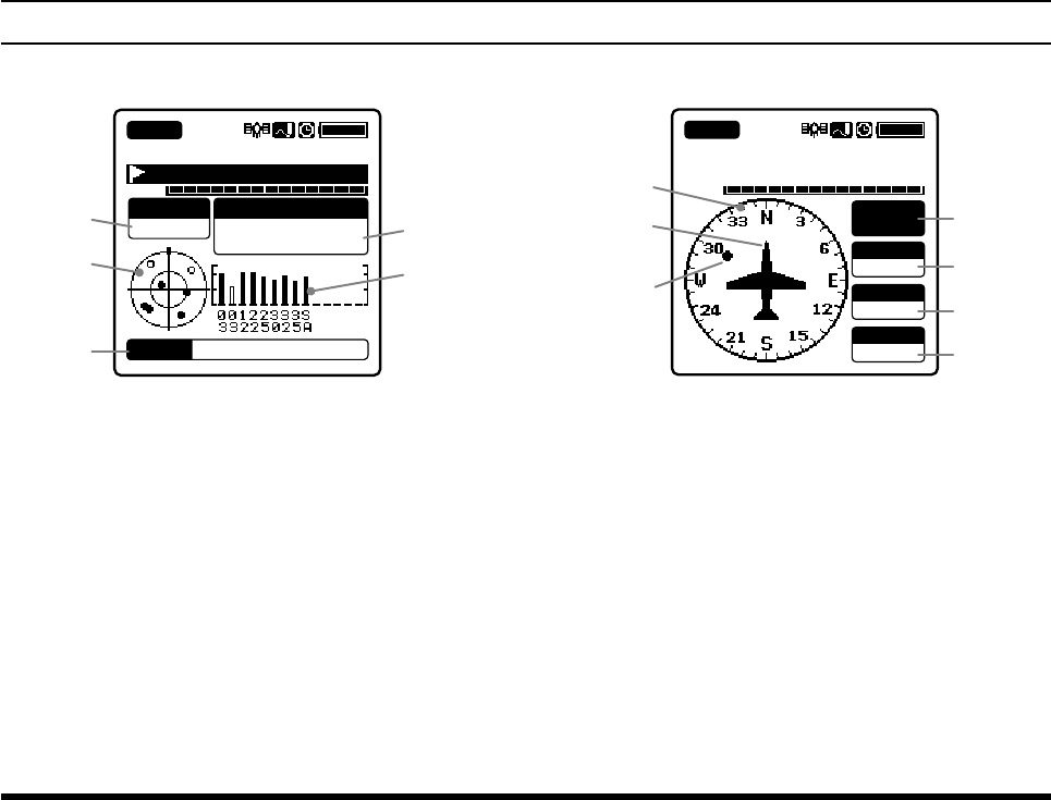
lcd dIsplay (Fta-750 only)
gps status screen
133.800
VOL
BUSY
FLG
MR
KLAX-ATIS
LAT/LON
23°
56.890N
123°
56.890W
Oct/25 09:56AM
DATE
STATUS
SEARCH
GPS receiver operation status
Radar scope for captured GPS satellites
Date obtained from the GPS signal
Latitude and longitude values
GPS signal strength indicator
WaypoInt naVIgatIon screen
133.800
VOL
SOGkph
360
COG T
000°
DSTkm
10
KLAX
BUSY
KLAX-ATIS
MR
ALL
Compass rose
Course indicator
Destination indicator
Tag name of the destination
DST (distance) value
COG (course over ground) value
SOG (speed over ground) value
FCC ID: K6650013X20
IC: 511B-50013X20
FTA-750/FTA-550/FTA-450 OperATing MAnuAl
12
BeFore you BegIn
Battery Installation and Removal
To install the battery, insert the battery pack SBR-
12LI into the battery compartment on the back of
the
transceiver
, press the end of the battery pack
while pressing the battery pack latch on the bot-
tom of the
transceiver
, then lock the pack by sliding
the locking plate beside the latch until the entire
“LOCK” appears
.
Note:
Be sure that the rubber gasket on the SBR-12LI is
not loose when inserting.
To remove the battery, turn the
transceiver
off, slide
the locking plate until the
“UNLOCK” appears
en-
tirely
, lift up the
end of the battery pack by pressing
the battery pack latch, then pull out the battery from
the radio.
PUSH
DATA
MIC/SP
EXT
DC
Battery Pack
Latch
Do not attempt to open any of the recharge-
able Lithium-ion packs, as personal injury
or damage to the Lithium-ion pack could
occur if a cell or cells become accidentally short-
circuited.
Note:
To remove the battery pack after the belt clip SHB-11 is
mounted (see Page 16), lift up the clip before you press
the battery pack latch.
FCC ID: K6650013X20
IC: 511B-50013X20
FTA-750/FTA-550/FTA-450 OperATing MAnuAl 13
BeFore you BegIn
side of the transceiver directly. In this case, the
“ ” icon will appear in the top right corner
of the LCD display.
4. If the transceiver is inserted correctly, the RED indi-
cator on the SBH-11 will glow.
A fully-discharged pack will be charged com-
pletely in 4 hours, and then the GREEN indica-
tor on the SBH-11 will glow.
It takes 8 hours for full charge with the SAD-
11 connected to the transceiver directly.
Important Notes:
The
SAD-11 is not designed to power the trans-
ceiver for operation (transmission).
Do not leave the charger connected to the trans-
ceiver for continuous periods in excess of 24 hours.
Long term overcharging can degrade the Lithium-
ion battery pack and signicantly shorten its useful
life.
If using a charger other than the SAD-11, SBH-11,
or if using a battery pack other than the SBR-12LI,
follow the appropriate instructions provided with
the charger/battery. Contact your Dealer if you have
any doubts about the appropriateness of the particu-
lar charger or battery pack you intend to use.
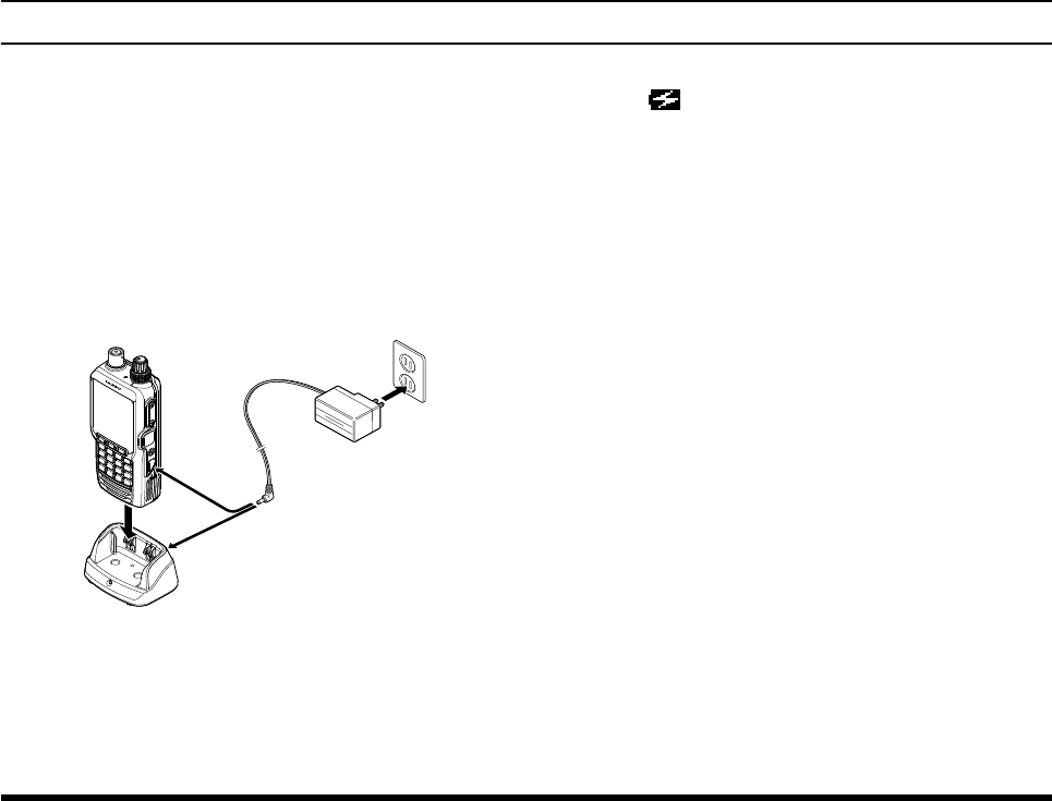
Battery Charging
It is necessary to charge the Lithium-ion battery fully
before its rst use. Follow the procedure below:
1.
Install the Lithium-ion battery pack onto the trans-
ceiver. Ensure that the transceiver is switched off.
2. Insert the cable plug of the SAD-11 Battery Char-
ger into the jack located on the back of the SBH-11
Charging Cradle, then plug the SAD-11 into the AC
line outlet.
EXT
DC
MIC/SP
DATA
VOL
DIAL
SBH-11
SAD-11
3. Insert the transceiver into the SBH-11; the antenna
jack should be at the left side when viewing the
cradle from the front.
You may insert the cable plug of the SAD-
11 into the EXT DC jack located on the right
FCC ID: K6650013X20
IC: 511B-50013X20
FTA-750/FTA-550/FTA-450 OperATing MAnuAl
14
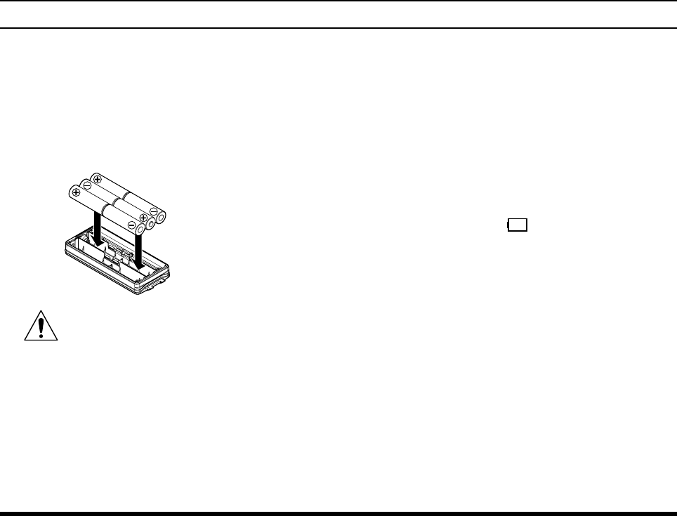
Alkaline Battery Tray Installation
The
supplied
SBT-12 Battery Tray allows operation of
the FTA-750/FTA-550/FTA-450 using six “AA” size
alkaline battery cells.
When installing a cell, insert the (–) end rst, then
press in the (+) end so the cell snaps into place. Pay
attention to the polarity indicated inside the case.
SBT-12
Alkaline Battery Tray
The SBT-12 must not be used with re-
chargeable cells. The SBT-12 does not con-
tain the thermal and over-current protec-
tion circuits required when utilizing Ni-Cd and Ni-
MH cells.
Note: Replace all six cells at the same time in case of
low battery.
To install the SBT-12, remove the Lithium-ion bat-
tery pack first from the transceiver, turn the open
side of the SBT-12 down, then insert it into the bat-
tery compartment.
Note: Be sure that the rubber gasket on the SBT-12
is not loose when inserting.
Low Battery Indication
As your battery discharges during use, the voltage will
gradually become lower. When the battery voltage
reaches 6.0 Volts, the “ ” icon will blink on the
LCD display, indicating that the battery pack must be
recharged or the alkaline battery cells must be replaced
before further use.
Avoid recharging Lithium-ion batteries before the
“Low Battery” indicator is observed, as this can
degrade the charge capacity of your Lithium-ion
battery pack. YAESU recommends that you carry an
extra, fully-charged pack with you so you will not
lose communications capability due to a depleted
Lithium-ion battery.
The fully-charged battery lasts for 12 hours on the
FTA-750, 13.5 hours on the FTA-550 or ??.? hours
on the FTA-450 under the conditions below:
Battery saver ... OFF
Operation ratio ... TX:RX:Standby = 6:6:48 (sec)
BeFore you BegIn
FCC ID: K6650013X20
IC: 511B-50013X20
FTA-750/FTA-550/FTA-450 OperATing MAnuAl 15
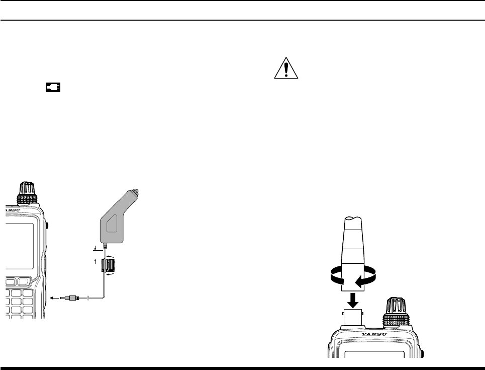
External DC Power Supply Connection
You may insert the cable plug of the optional SDD-12
Cigarette Lighter DC/DC Converter into the EXT DC
jack located on the right side of the transceiver. In this
case, the “ ” icon will appear in the top right corner
of the LCD display.
When making DC connections via the SDD-12, be ab-
solutely certain to observe the proper voltage level and
polarity guidelines.
The SDD-12 can be connected to 12 to 24 Volt DC
power sources.
SDD-12
Cigarette Lighter DC/DC
Converter (12 to 24 Volts)
Ferrite Core
Wind the cable one turn,
then snap two halves
As close
as possible
For noise reduction from exogenous noise, wind one
turn of the SDD-12 cable around the ferrite core,
and snap its two halves together, per the illustration
above. Attach the ferrite core as close as possible to
the SDD-12 body, as shown.
Do not connect any accessory unapproved
by YAESU to supply DC power; otherwise
the FTA-750/FTA-550/FTA-450 may be
damaged.
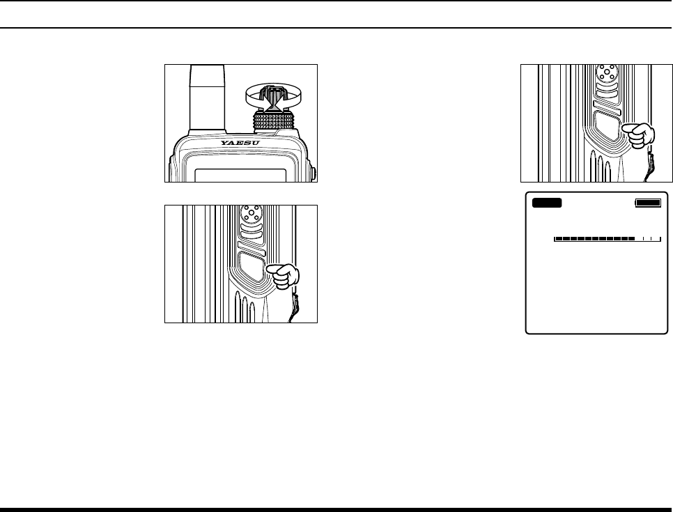
Antenna Installation
To attach the supplied antenna to the FTA-750/
FTA-550/FTA-450, grasp the base of the antenna
rmly, and exert a moderate “pinching” pressure on
the base as you press the antenna onto the radio’s
antenna connector. While exerting this pressure,
rotate the antenna clockwise 1/4 turn to lock the an-
tenna in place.
BeFore you BegIn
FCC ID: K6650013X20
IC: 511B-50013X20
FTA-750/FTA-550/FTA-450 OperATing MAnuAl
16
BeFore you BegIn
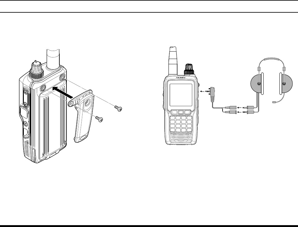
Belt Clip Installation
You may mount the clip to the rear of the FTA-750/
FTA-550/FTA-450 using the supplied screws.
DATA
MIC/SP
EXT
DC
DATA
MIC/SP
EXT
DC
SHB-11
Belt Clip
with two screws (M3 x 8)
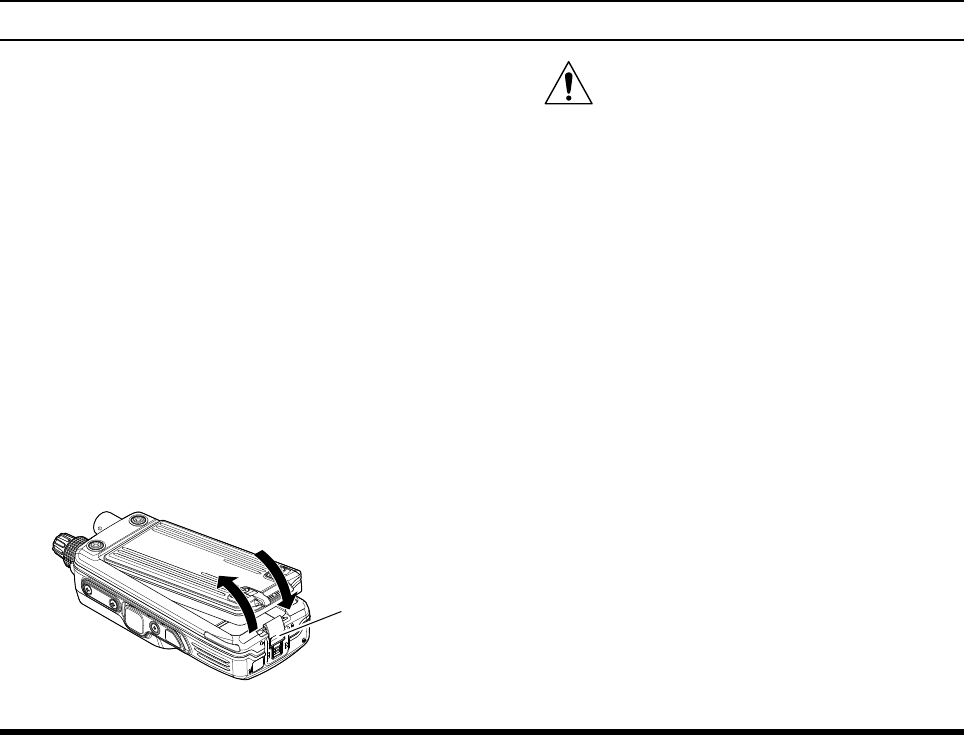
Headset Connection
You may use an optional headset through the supplied
SCU-15 Headset Adapter Cable (see also Page 87).
Headset
(not supplied)
SCU-15
Headset Adapter Cable
1. Remove the cover and two screws of the MIC/SP
jack located on the right side of the transceiver.
2. Insert the plug of the SCU-15 to the MIC/SP jack.
3. Fix the plug with two screws attached to the SCU-
15.
Either of the plug directions are acceptable as
long as the both screws t the screw holes.
4. Insert the plugs of the headset to the sockets of the
SCU-15.
FCC ID: K6650013X20
IC: 511B-50013X20

FTA-750/FTA-550/FTA-450 OperATing MAnuAl 17
BeFore you BegIn
Precautions
The
FTA-750/FTA-550/FTA-450 are capable of
two-way communication on channels used for criti-
cal aviation safety communications. Therefore, it is
important that this radio be kept away from children
or other unauthorized users at all times.
Do not dispose of the Lithium-ion battery pack in a
re. Do not carry a Lithium-ion battery pack in your
pocket, where keys or coins could short the termi-
nals. This could create a serious fire/burn danger,
and possibly cause damage to the Lithium-ion pack.
The
FTA-750/FTA-550/FTA-450 are designed to
have the waterproof capability equivalent to IPX5.
Do not allow the radio to become submerged, and
do not subject it to water spray under pressure.
FCC ID: K6650013X20
IC: 511B-50013X20
FTA-750/FTA-550/FTA-450 OperATing MAnuAl
18
BasIc operatIon
Reception (COM Band)
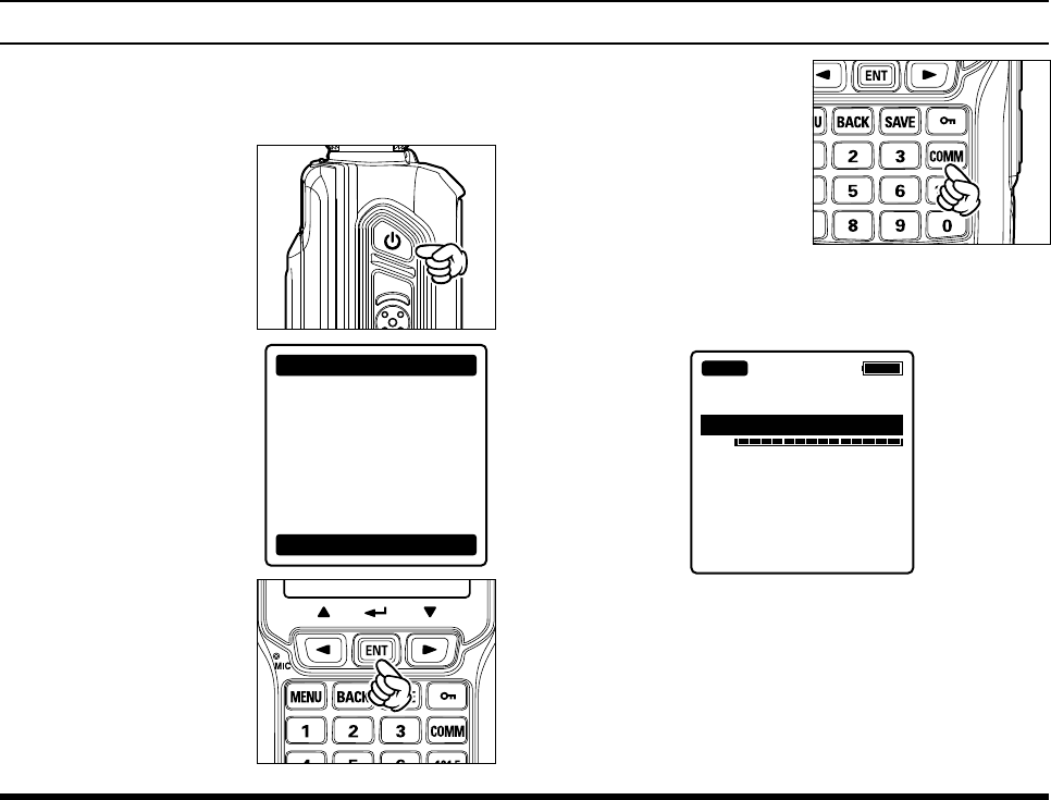
Turning the radio on and off
To turn the radio on,
press and hold the
POWER switch.
“WARNING” will be
displayed. PTT
SQL
This device can only
be used as an aid to
navigation for VFR.
All information
is presented for
reference only.
You assume total
responsibility and
risk associated with
using this device.
WARNING
I agree
If you agree with the
warning message, press
the [ENT] key.
A channel frequency will
appear on the display. If
not, press the [COMM]
key.
The “
BUSY
” icon appears on the display when the
audio signal is received on the current frequency.
127.300
VOL
BUSY
To turn the radio off, press and hold the POWER
switch.
FCC ID: K6650013X20
IC: 511B-50013X20
FTA-750/FTA-550/FTA-450 OperATing MAnuAl 19
BasIc operatIon
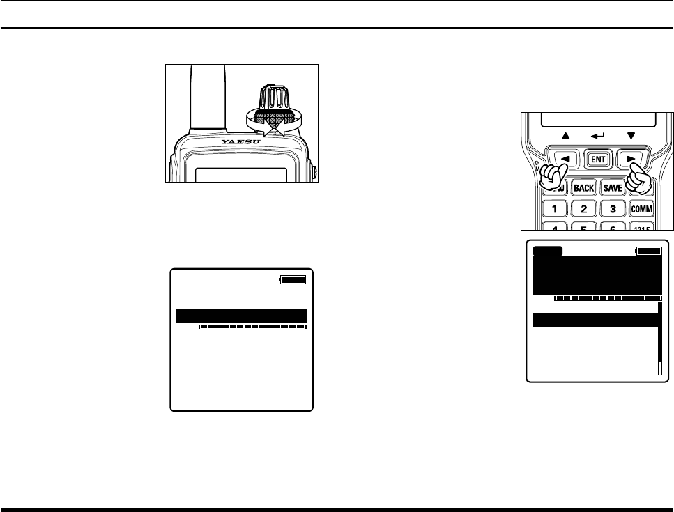
Adjusting the frequency
You may turn the DIAL
selector (outer) knob on
the top panel to choose
the desired operating
frequency. The channel
frequency will appear
on the LCD.
Directly entering frequencies from the keypad is the
easiest method if you know the frequency on which
you wish to operate. Just enter the ve digits of the
frequency to move to that frequency.
For example, to set
134.35 MHz,
press
[1] [3] [4]
[3] [5].
To set 118.275 MHz,
you do not need to
press the nal “5” in the
frequency as below:
[1] [1] [8] [2]
[7].
13-.---
VOL
You may recall the operating frequency that you
have used by pressing the [ENT] key.
A list of frequencies you have used will appear be-
low the VOL meter on the display.
Select the desired fre-
quency by pressing the
[◄] or [►] key, then
press the [ENT] key.
133.800
VOL
132.400
134.800
127.600
119.150
124.250
129.200
BUSY
FCC ID: K6650013X20
IC: 511B-50013X20
FTA-750/FTA-550/FTA-450 OperATing MAnuAl
20
Adjusting the volume
Rotate the VOL (inner)
knob to set the volume
level. If no signal is
present, press the SQL
switch; background
noise will now be heard,
and you may use this
noise to set the VOL
knob for the desired
audio level. Press and
hold the SQL switch
to silence the noise and
resume normal (quiet)
monitoring.
PTT
SQL
Adjusting the squelch
Press the SQL switch,
then rotate the DIAL
selector knob to set the
squelch threshold (0 to
15) so that the receiver
is just silenced. A high-
er number indicates that
a higher signal level
is required in order to
open the squelch.
PTT
SQL
127.300
BUSY
SQL
Press and hold the SQL switch to set the squelch
threshold to 0 (off).
Your new setting will be saved each time you per-
form either of the operations above.
BasIc operatIon
FCC ID: K6650013X20
IC: 511B-50013X20
FTA-750/FTA-550/FTA-450 OperATing MAnuAl 21
BasIc operatIon
Monitor Switch
When listening to a very weak signal from an aircraft or
ground station, you may observe the signal disappearing
periodically as the incoming signal strength becomes too
weak to override the squelch threshold setting.
To disable the squelch temporarily, press and hold the
SQL switch for 2 seconds. The squelch will remain
open and you should have a better chance of hearing
weak signals.
To return to normal operation, press the SQL momen-
tarily.
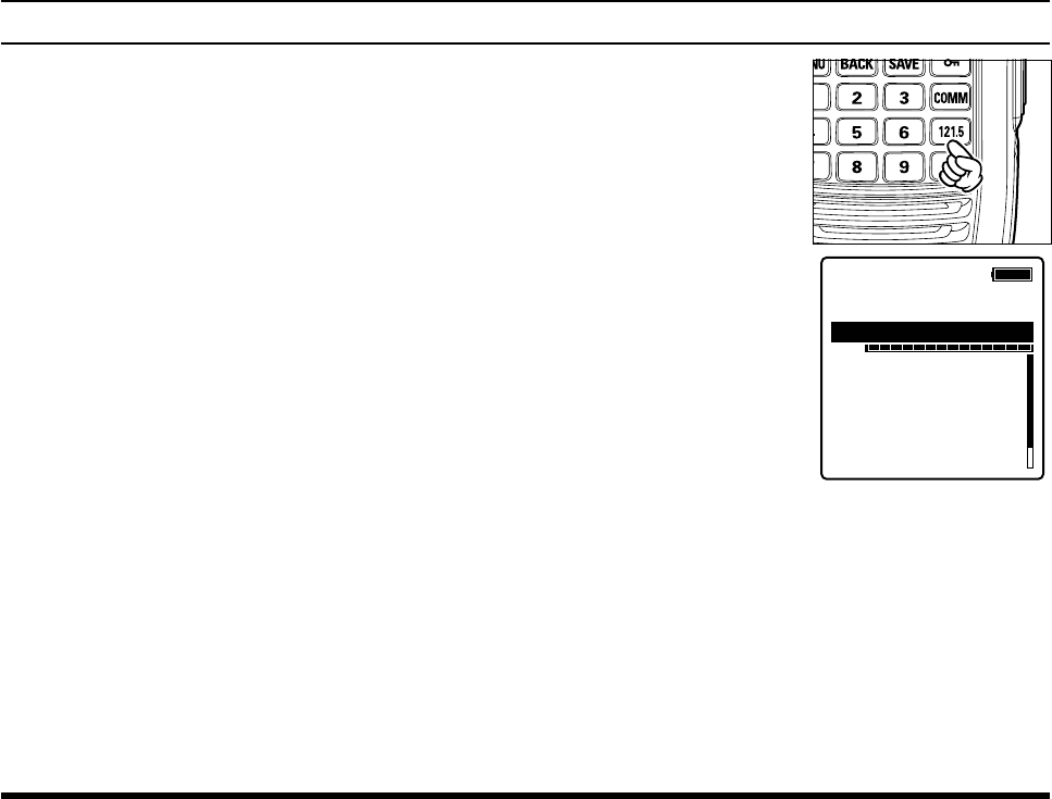
Accessing the 121.5 MHz Emergency Frequency
The FTA-750/FTA-550/FTA-450 can quickly access
the 121.500 MHz emergency frequency. This function
can be activated even when the keypad lock function
(described on Page 46) is in use.
To access the emergen-
cy frequency, press and
hold the [121.5] key.
After four beeps, the
transceiver enters the
emergency mode and
the frequency is au-
tomatically tuned to
121.500 MHz.
121.500
VOL
132.400
134.800
127.600
119.150
124.250
129.200
EMERGENCY
EMG
To exit the emergency mode, press the [COMM]
key. The message conrming the cancelation of the
emergency mode will appear. Press the [◄] or [►]
key to select “YES”, then press the [ENT] key.
FCC ID: K6650013X20
IC: 511B-50013X20
FTA-750/FTA-550/FTA-450 OperATing MAnuAl
22
BasIc operatIon
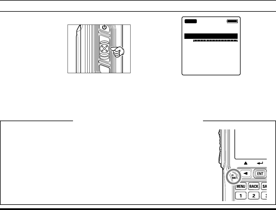
Transmission (COM Band)
To transmit, press and
hold the PTT switch.
Speak into the micro-
phone area of the front
panel grille in a normal
voice level.
The “
TX
” icon, which
indicates that the FTA-
750/FTA-550/FTA-
450 are in the transmit
mode, appears on the
display.
PTT
SQL
127.300
VOL
TX
To return to the receive mode, release the PTT
switch.
Operating Advice: Use of Internal Microphone
Your FTA-750/FTA-550/FTA-450 are sealed against water ingress, which includes wa-
terproof seals around the microphone and speaker enclosure. This requires that you fo-
cus your speech in the direction of the microphone’s location, so as to ensure sufcient
voice input to the radio. Refer to the illustration and observe the location of the internal
microphone.
If you find it difficult to utilize the FTA-750/FTA-550/FTA-450 conveniently and
safely while speaking directly into the microphone, we recommend the use of the SSM-
10A Speaker/Microphone (option), or an aftermarket aviation headset with boom mi-
crophone.
FCC ID: K6650013X20
IC: 511B-50013X20
FTA-750/FTA-550/FTA-450 OperATing MAnuAl 23
BasIc operatIon
Operation Bands
When the FTA-750/FTA-550/FTA-450 are turned on
for the rst time, it enters the COMM mode and displays
the COM band screen. The COMM mode is the basic
operation mode of the FTA-750/FTA-550/FTA-450
that
allows you to tune through either of the NAV (except
for
FTA-450
) and COM bands using the DIAL knob or
the keypad.
NAV band (108.000 - 117.975
MHz):
Band for navigation utilizing data signals emitted by
VOR (VHF omnidirectional range) stations and ILS
(instrument landing system) of airports.
COM band (118.000 - 136.975
MHz):
Band for communication utilizing audio signals.
When the FTA-750/FTA-
550 receive a data signal
associated with VOR or
ILS, the display will auto-
matically switch to the NAV
band screen which shows a
CDI (course deviation indi-
cator) based on the received
signal, and “
NAV
”, which
indicates that the FTA-750/
FTA-550 are on the NAV
band, appears on the dis-
play.
113.600
VOL
SOGKT
150
355°
OBS
000°
NAV VOR
FROM
KLAX-VOR
N
S
EW
33
24
21 15
12
30
3
6
When receiving a VOR
signal on the FTA-750
FCC ID: K6650013X20
IC: 511B-50013X20
FTA-750/FTA-550/FTA-450 OperATing MAnuAl
24
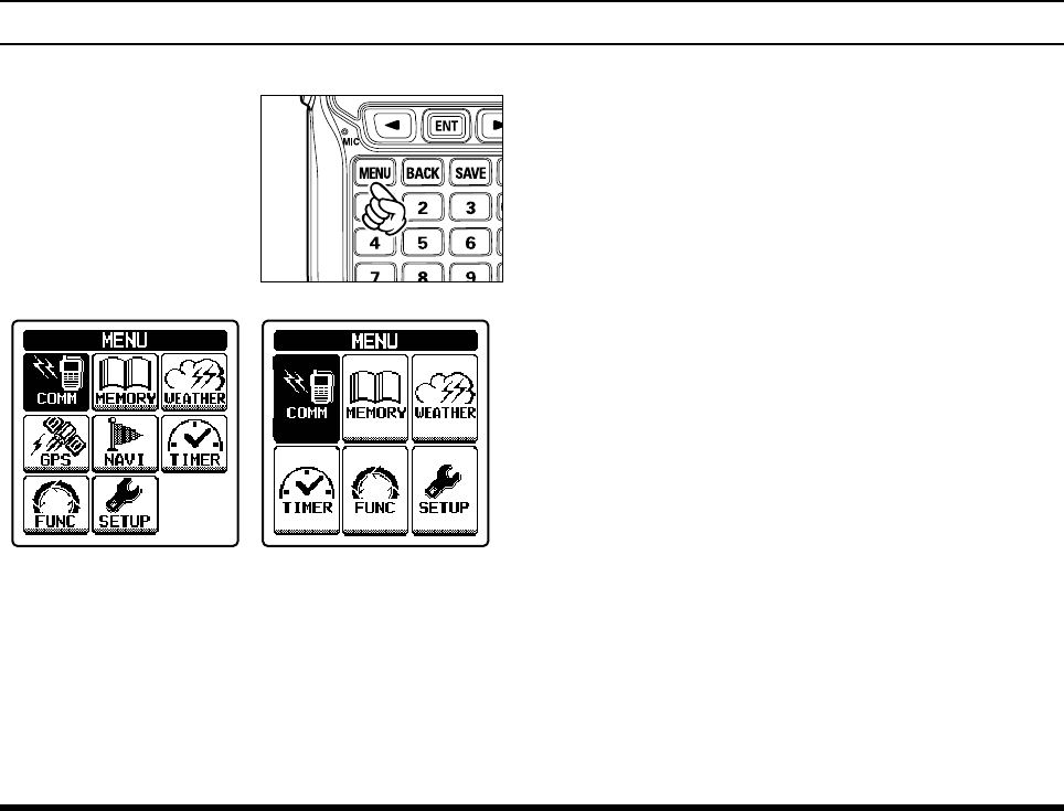
Operation Modes
The FTA-750/FTA-550/
FTA-450 operate in either
of the modes below. You
can switch the modes via
the MENU screen displayed
by pressing the [MENU]
key on the front panel.
FTA-750 FTA-550
When turning on the FTA-750/FTA-550/FTA-450, the
last mode you have used before turning off will auto-
matically be entered.
COMM
The basic operating mode for communication. Navi-
gation through the NAV band is also performed on
this mode.
MR
(MEMORY)
This mode provides you with the ability to store and
recall as many as 200 channels in the radio’s main
memory bank.
WX
(WEATHER) (USA/Canada Only)
The receive mode for the VHF weather chan-
nel broadcasts. 10 weather channels are pre-pro-
grammed at the factory.
GPS (FTA-750 only)
The position information and status of the GPS sat-
ellites according to the signals received by the built-
in GPS unit are displayed during this mode.
NAVI (FTA-750 only)
Navigation to the waypoint (destination) memorized
or manually input is carried out in this mode.
SETUP
This mode allows certain aspects of your radio’s
configuration to be customized for your personal
operating conditions.
BasIc operatIon
FCC ID: K6650013X20
IC: 511B-50013X20
FTA-750/FTA-550/FTA-450 OperATing MAnuAl 25
BasIc operatIon
Convenient menu items
The MENU screen also includes the following items
which provide advanced and convenient usage of the
FTA-750/FTA-550/FTA-450.
TIMER
You may use the FTA-750/FTA-550/FTA-450 as a
countdown timer or a stopwatch through this menu.
FUNCTION
Enables and disables various functions such as scan
and dual watch features through this menu.
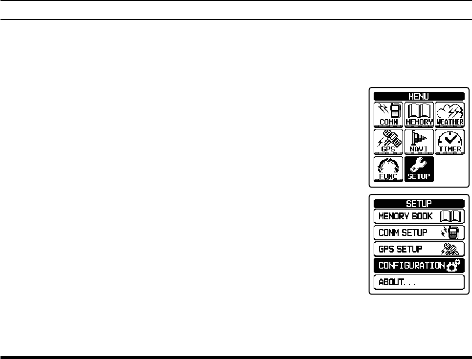
Resetting the Radio
To clear all memories and other settings to factory de-
faults:
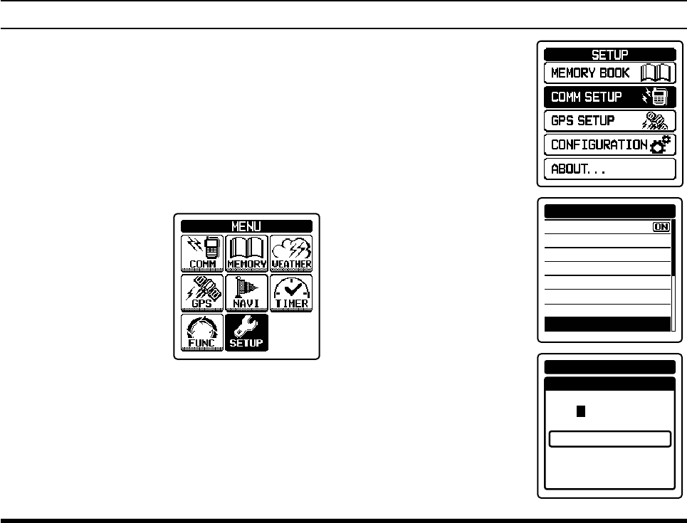
1.
Press the
[MENU] key to display the MENU screen
.
2. Select
“SETUP” on the
screen by pressing the
[◄] or [►] key, and
then press the [ENT]
key.
3. Select “CONFIGURA-
TION” on the screen by
pressing the [◄] or [►]
key, and then press the
[ENT] key.
FCC ID: K6650013X20
IC: 511B-50013X20
FTA-750/FTA-550/FTA-450 OperATing MAnuAl
26
BasIc operatIon
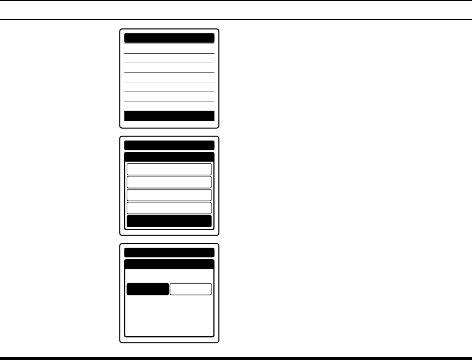
4.
Select
“RESET” on the
screen by pressing the
[◄] or [►] key, and
then press the [ENT]
key.
LAMP
CONTRAST
KEY BEEP
TIMER ALARM
BATTERY SAVE
LOCK SELECT
PTT LOCK
RESET
CONFIGURATION
5.
Select
“FACTORY” on
the screen by pressing
the [◄] or [►] key, and
then press the [ENT]
key.
RESET
FUNCTION
MEMORY
COMM & GPS
CONFIGURATION
FACTORY
CONFIGURATION
6.
Select
“OK?” on the
screen by pressing the
[◄] or [►] key, and
then press the [ENT]
key.
RESET
FACTORY
CANCEL
CONFIGURATION
OK?
The initialization will start and then “COMPLETED!”
will be displayed after the radio returns to factory
default.
FCC ID: K6650013X20
IC: 511B-50013X20
FTA-750/FTA-550/FTA-450 OperATing MAnuAl 27
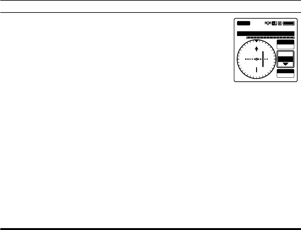
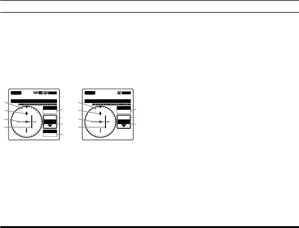
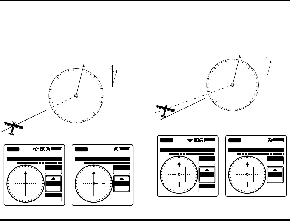
Reception of VOR Signals (except for FTA-450)
When the FTA-750/FTA-550 receive a VOR (VHF
omnidirectional range) signal, the display will automati-
cally switch to the NAV band screen which shows a
CDI (course deviation indicator) based on the received
signal, and “
VOR
”, which indicates that the FTA-750/
FTA-550 are receiving the VOR signal, appears on the
display.
113.600
VOL
SOGKT
150
355°
OBS
000°
NAV VOR
FROM
KLAX-VOR
N
S
EW
33
24
21 15
12
30
3
6
113.600
VOL
355°
OBS
000°
NAV VOR
FROM
KLAX-VOR
N
S
EW
33
24
21 15
12
30
3
6
FTA-750 FTA-550
Compass rose
Course indicator (OBS direction)
Deviation marks
Course deviation needle
OBS (omni bearing selector) value
VOR value
TO/FROM indicator
SOG (speed over ground) value according to the
GPS signal
The OBS is set to 0 degree when you use the FTA-
750/FTA-550 for the rst time.
The last value you have set as the OBS will be dis-
played next time the NAV band screen appears.
The upside of the compass rose always indicates the
direction set as the OBS.
When the OBS is set to a degree within the “TO”
range relative to the VOR signal, the FTA-750/
FTA-550 displays a degree adding (or subtracting)
180° to (or from) the VOR signal as the VOR value.
The SOG is displayed only when the internal GPS
unit is activated and receives a x in the FTA-750.
Note:
You may change the COM band receive frequency while
receiving a VOR signal. If the [ENT] key is pressed
during the tag name of the VOR station is selected,
the recall screen listing the frequencies you have used
will temporarily appear on the display, so that you may
select a frequency from the list with the [◄] or [►] key
or change the frequency with the DIAL selector knob.
adVanced operatIon
FCC ID: K6650013X20
IC: 511B-50013X20
FTA-750/FTA-550/FTA-450 OperATing MAnuAl
28
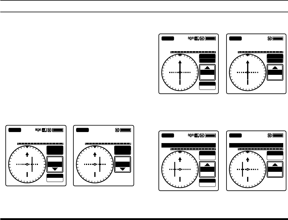
Reading the CDI
If the OBS is set to 50° and your aircraft is at 230°
from a certain VOR station, for example, you are “on
course” and the course deviation needle of the CDI
will be at the center of the compass rose.
10°
0°
20° 30°
40°
50°
60°
70°
80°
90°
100°
110°
120°
130°
140°
150°
160°
170°
180°
190°
200°
210°
220°
240°
250°
260°
270°
280°
290°
310°
320°
330°340° 350°
300°
230°
VOR
Station
Magnetic
North
N
OBS 50°
VOR 230°
113.600
VOL
SOGKT
150
050°
OBS
050°
NAV VOR
TO
KLAX-VOR
N
S
E
W
33
24 21
15
12
30
36
113.600
VOL
OBS
050°
NAV VOR
TO
KLAX-VOR
N
S
E
W
33
24 21
15
12
30
36
050°
FTA-750 FTA-550
If the OBS is set to 50° but your aircraft is at 236°
from a certain VOR station, for example, you are “off
course” and the course deviation needle of the CDI
will be inside the right half of the compass rose.
10°
0°
20° 30°
40°
50°
60°
70°
80°
90°
100°
110°
120°
130°
140°
150°
160°
170°
180°
190°
200°
210°
220°
230°
240°
250°
260°
270°
280°
290°
310°
320°
330°340° 350°
300°
VOR
Station
Magnetic
North
N
OBS 50°
VOR 236°
113.600
VOL
SOGKT
150
OBS
050°
NAV VOR
TO
KLAX-VOR
N
S
E
W
33
24 21
15
12
30
36
056°
113.600
VOL
OBS
050°
NAV VOR
TO
KLAX-VOR
N
S
E
W
33
24 21
15
12
30
36
056°
FTA-750 FTA-550
adVanced operatIon
FCC ID: K6650013X20
IC: 511B-50013X20
FTA-750/FTA-550/FTA-450 OperATing MAnuAl 29
adVanced operatIon
The course deviation needle moves to the right if
your aircraft is off course to the left of the OBS, or
moves to the left if your aircraft is off course to the
right of the OBS.
The deviation marks indicate off-course level by
2 degrees up to 10 degrees per each side. If your
deviation exceeds 10 degrees, the course deviation
needle will stay at the position of the fth mark (the
end of the scale) of the left or right side.
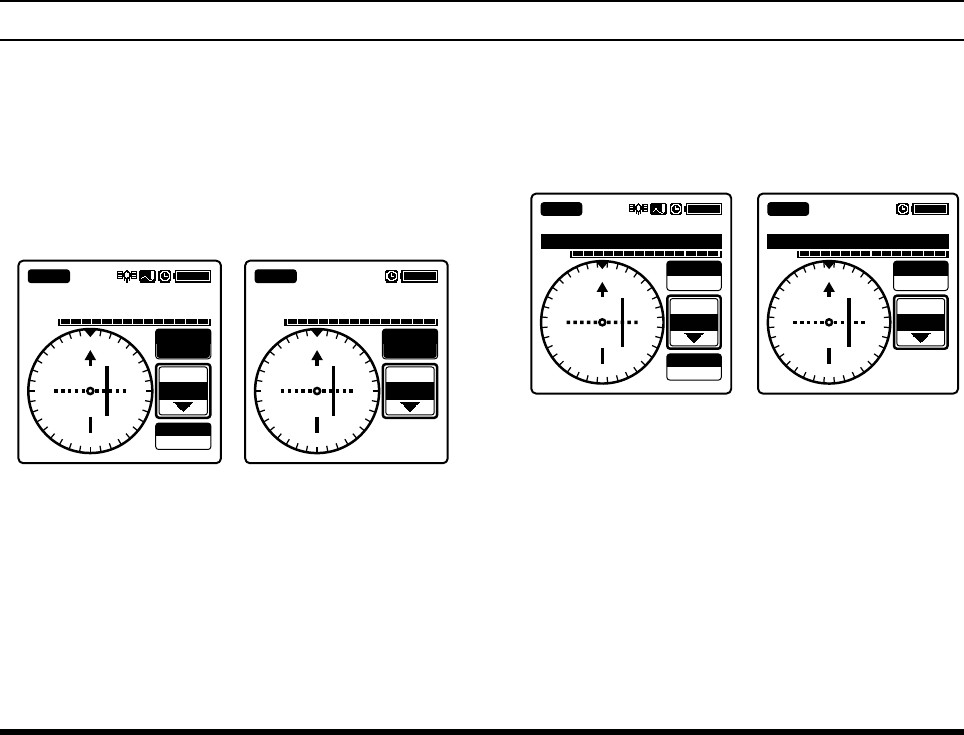
Flying to a VOR station
1. Set the frequency to the desired VOR station
.
2. Press
the [◄] or [►] key to
select
“OBS” on the
screen.
113.600
VOL
SOGKT
150
355°
OBS
000°
NAV VOR
FROM
KLAX-VOR
N
S
EW
33
24
21 15
12
30
3
6
113.600
VOL
355°
OBS
000°
NAV VOR
FROM
KLAX-VOR
N
S
EW
33
24
21 15
12
30
3
6
FTA-750 FTA-550
3. Enter the course to the VOR station with the keypad
or the
DIAL knob.
113.600
VOL
SOGKT
150
OBS
175°
NAV VOR
TO
KLAX-VOR
N
S
EW
33
24
21
15
12
30
3
6
175°
113.600
VOL
OBS
175°
NAV VOR
TO
KLAX-VOR
N
S
EW
33
24
21
15
12
30
3
6
175°
FTA-750 FTA-550
4. Correct your course until the course deviation
needle on the screen is at the center of the compass
rose.
113.600
VOL
SOGKT
150
OBS
175°
NAV VOR
TO
KLAX-VOR
S
N
W
E
15
6
333
30
12 21
24
170°
113.600
VOL
OBS
175°
NAV VOR
TO
KLAX-VOR
N
S
EW
33
24
21
15
12
30
3
6
170°
FTA-750 FTA-550
FCC ID: K6650013X20
IC: 511B-50013X20
FTA-750/FTA-550/FTA-450 OperATing MAnuAl
30
adVanced operatIon
Flying to a desired course
If you know the direction of your destination from a
specic VOR station, you may use the CDI to correct
your course of ying.
1. Set the frequency to the desired VOR station
.
2. Press
the [◄] or [►] key to
select
“OBS” on the
screen.
113.600
VOL
SOGKT
150
355°
OBS
000°
NAV VOR
FROM
KLAX-VOR
N
S
EW
33
24
21 15
12
30
3
6
113.600
VOL
355°
OBS
000°
NAV VOR
FROM
KLAX-VOR
N
S
EW
33
24
21 15
12
30
3
6
FTA-750 FTA-550
3. Enter the course from the VOR station with the key-
pad or the
DIAL knob.
4. Correct your course until the course deviation
needle on the screen is at the center of the compass
rose.
113.600
VOL
SOGKT
150
350°
OBS
355°
NAV VOR
FROM
KLAX-VOR
N
S
E
W
33
24
21 15
12
30 3
6
113.600
VOL
350°
OBS
355°
NAV VOR
FROM
KLAX-VOR
N
S
E
W
33
24
21 15
12
30 3
6
FTA-750 FTA-550
FCC ID: K6650013X20
IC: 511B-50013X20
FTA-750/FTA-550/FTA-450 OperATing MAnuAl 31
adVanced operatIon
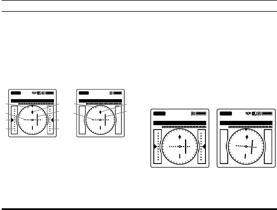
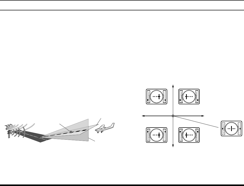
Reception of ILS Signals (except for FTA-450)
When the FTA-750/FTA-550 receive an ILS (instru-
ment landing system) signal, the display will automati-
cally switch to the NAV band screen which shows a
CDI (course deviation indicator) based on the received
signal, and “
LOC
”, which indicates that the FTA-750/
FTA-550 are receiving the localizer signal, and “
GS
”,
which indicates that the FTA-750 is receiving the glide
slope signal, appear on the display.
108.500
VOL
NAV
LOC
GS
KLAX-RWY07R
N
S
EW
33
24
21 15
12
30
3
6
108.500
VOL
NAV
LOC
KLAX-RWY07R
FTA-750 FTA-550
Compass rose
Course (runway) indicator
Deviation marks for localizer
Course deviation needle for localizer
Height deviation indicator for glide slope
Deviation marks for glide slope
In the FTA-750 when the internal GPS unit is not
activated or cannot receive a x even it is activated,
or in the FTA-550, the upside of the compass rose
always indicates the direction of the runway and
no sign indicating the bearings is displayed on the
compass rose.
In the FTA-750 when the internal GPS unit is acti-
vated and receives a x, the compass rose rotates to
display the approaching course up. The course in-
dicator, deviation marks, and deviation needle also
rotate to display the runway direction if registered
in advance.
108.500
VOL
NAV
LOC
GS
KLAX-RWY07R
108.500
VOL
NAV
LOC
KLAX-RWY07R
N
S
EW
33
24
21 15
12
30
3
6
Without GPS With GPS, no GS signal,
runway direction registered
FCC ID: K6650013X20
IC: 511B-50013X20
FTA-750/FTA-550/FTA-450 OPERATING MANUAL
32
adVanced operatIon
Note:
You may change the COM band receive frequency
while receiving an ILS signal. If the [ENT] key is
pressed while the tag name of the airport is selected,
the recall screen listing the frequencies you have used
will temporarily appear on the display, so that you may
select a frequency from the list with the [◄] or [►] key
or change the frequency with the DIAL selector knob.
Terminology:
The localizer signal guides the approach to the
runway in horizontal direction.
The glide slope signal guides the approach to the
runway in vertical direction. Note that some airports
are unequipped with the glide slope.
Runway
Course of approach
Guided by
glide slope
Glide slope
Localizer
Guided by
localizer
Reading the CDI
The course deviation needle moves to the right if
your aircraft is off course to the left of the runway,
or moves to the left if your aircraft is off course to
the right of the runway.
The height deviation indicator moves up if your
aircraft ies lower than the ideal altitude, or moves
down if your aircraft ies higher than the ideal alti-
tude.
Right
(LOC)
Left
(LOC)
High
(GS)
On course
Low
(GS)
CDI Examples Corresponding to Aircraft Location
(Runway is to be at the back of the screen)
FCC ID: K6650013X20
IC: 511B-50013X20
FTA-750/FTA-550/FTA-450 OperATing MAnuAl 33
adVanced operatIon
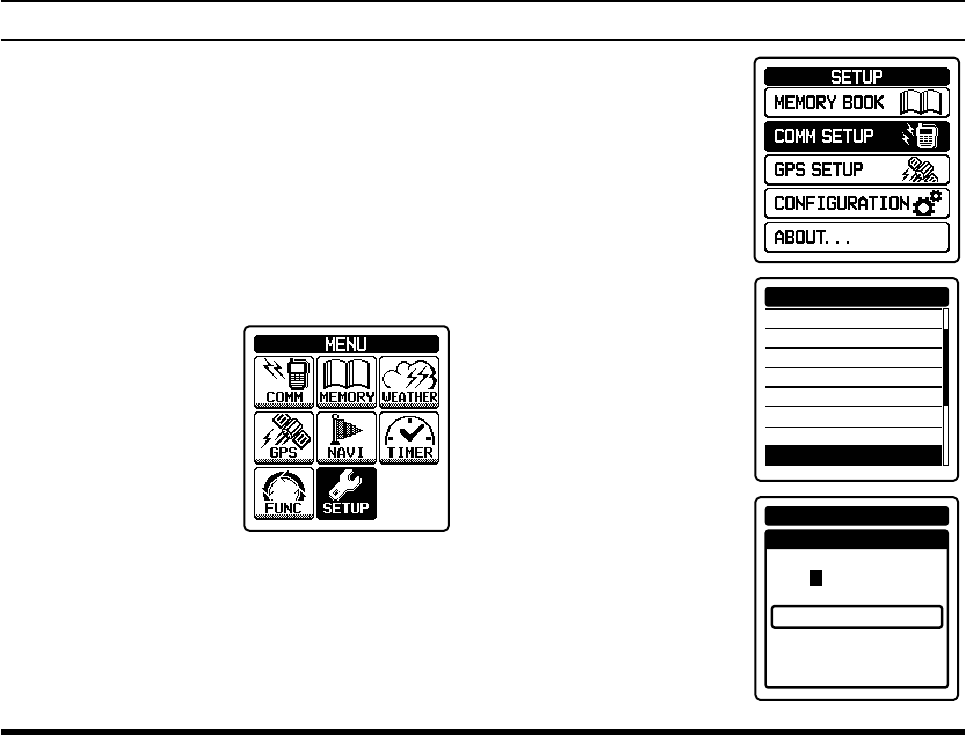
Split Operation
The split operation feature allows you to transmit a call
to a ight service station using the COM band frequen-
cies, while receiving a station in the NAV band. VOR
stations equipped with this capability typically are
shown, on navigation charts, with the voice calling fre-
quency in parenthesis above the navigation frequency.
Programming a transmit frequency
1.
Press the
[MENU] key to display the MENU screen
.
2. Select
“SETUP” on the
screen by pressing the
[◄] or [►] key, and
then press the [ENT]
key.
3. Select “COMM SET-
UP” on the screen by
pressing the [◄] or [►]
key, and then press the
[ENT] key.
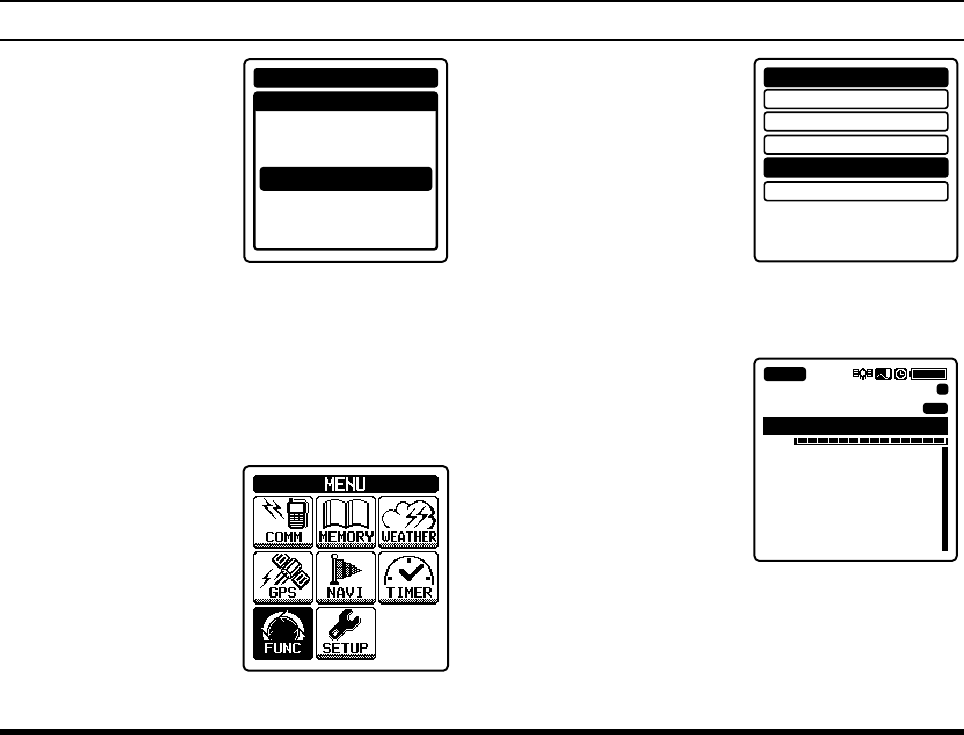
4.
Select
“SPLIT FRE-
QUENCY” on the screen
by pressing the [◄] or
[►] key, and then press
the [ENT] key.
ANL
WEATHER ALERT
SCAN BAND
PTT SCAN STOP
SCAN RESUME
SCAN STOP TYPE
DUAL WATCH FREQ.
SPLIT FREQUENCY
COMM SETUP
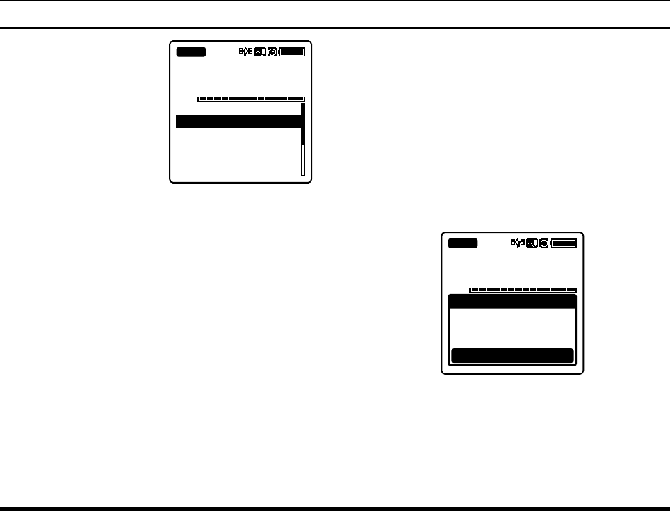
5.
Enter the transmit
frequency with the
keypad
.
COMM SETUP
SPLIT FREQUENCY
FINISH
---.---
MHz
FCC ID: K6650013X20
IC: 511B-50013X20
FTA-750/FTA-550/FTA-450 OperATing MAnuAl
34
adVanced operatIon
6.
Select
“FINISH” on the
screen by pressing the
[◄] or [►] key, and
then press the [ENT]
key.
The frequency will be
determined and the dis-
play will return to the
COMM SETUP menu.
COMM SETUP
SPLIT FREQUENCY
FINISH
122.100
MHz
Note:
Only the COM band frequencies can be set as the
transmit frequency.
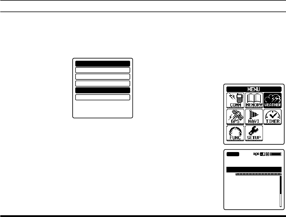
Activating the split mode
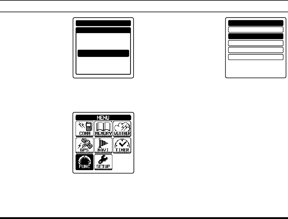
1.
Press the
[MENU] key to display the MENU screen
.
2. Select
“FUNC” on the
screen by pressing the
[◄] or [►] key, and
then press the [ENT]
key.
3. Select “SPLIT” on the
screen by pressing the
[◄] or [►] key, and
then press the [ENT]
key.
SCAN MEM
DUAL WATCH
SCAN
SPLIT
LOGGER
OFF
OFF
OFF
OFF
OFF
FUNCTION
If “ON” is displayed in the right hand of “SPLIT”,
the FTA-750/FTA-550/FTA-450 are already
in the split mode.
The display will return
to the previous screen
and the “
±
” icon, which
indicates that the FTA-
750/FTA-550/FTA-
450 are in the split
mode, will appear on
the display.
133.800
VOL
132.400 Las Vega
BUSY
Los Angeles
MR
MEM
±
FCC ID: K6650013X20
IC: 511B-50013X20
FTA-750/FTA-550/FTA-450 OperATing MAnuAl 35
adVanced operatIon
Operating in the split mode
To transmit a voice call during the NAV band recep-
tion, press and hold the PTT switch, and speak into
the microphone
.
The COM band screen will be dis-
played with the frequency you have set.
To exit the split mode,
select “SPLIT” and
press the [ENT] key in
the FUNCTION menu.
SCAN MEM
DUAL WATCH
SCAN
SPLIT
LOGGER
OFF
OFF
OFF
ON
OFF
FUNCTION
Reception of Weather Channel Broadcasts
- Weather Channels for USA/ Canada only -
The FTA-750/FTA-550/FTA-450 can receive VHF
weather channel broadcasts, which may assist your ight
planning. The FTA-750/FTA-550/FTA-450 include
a special bank capable of storing 10 weather channels,
which simplies access when you are in an unfamiliar
location.
To receive weather
channels, press the
[MENU] key, select
“WEATHER” on the
screen by pressing the
[◄] or [►] key, and
then press the [ENT]
key.
The last channel you
have tuned will be re-
ceived.
162.475
VOL
162.550 WX01
162.400 WX02
162.475 WX03
162.425 WX04
162.450 WX05
162.500 WX06
BUSY
WX03
FCC ID: K6650013X20
IC: 511B-50013X20
FTA-750/FTA-550/FTA-450 OperATing MAnuAl
36
adVanced operatIon
You can also select a
weather channel from
the pre-programmed list
with the DIAL selector
knob.
To conrm the weather
channel frequency se-
lection, press the [ENT]
key.
162.475
VOL
162.550 WX01
162.400 WX02
162.475 WX03
162.425 WX04
162.450 WX05
162.500 WX06
BUSY
WX03
To exit the WX mode, press the [MENU] key, se-
lect the mode other than “WEATHER” on the screen
by pressing the [◄] or [►] key, and then press the
[ENT] key.
Weather alert reception
In the event of extreme weather disturbances, such as
storms and hurricanes, the NOAA (National Oceanic
and Atmospheric Administration) sends a weather alert
accompanied by a 1050 Hz tone and subsequent weather
report on one of the NOAA weather channels.
When the radio receives the weather alert on the oper-
ating frequency, it displays a warning as below on the
screen and continues to make alarm sounds until either
of the keys is pressed.
VOL
BUSY
WX03
Radio received
Weather Alert!
WARNING
Press any keys
162.475
You may enable or disable the alarm function when re-
ceiving the weather alert signal via the COMM SETUP
menu, if desired. See Page 72 for details.
FCC ID: K6650013X20
IC: 511B-50013X20
FTA-750/FTA-550/FTA-450 OperATing MAnuAl 37
adVanced operatIon
Dual Watch Operation
The dual watch feature automatically checks for activity
on the P-ch (priority channel) set via the COMM SETUP
menu while you are operating on another channel. Dur-
ing the dual watch operation, the current channel and the
P-ch will be polled alternately for a 200 ms interval.
Setting the P-ch
1.
Press the
[MENU] key to display the MENU screen
.
2. Select
“SETUP” on the
screen by pressing the
[◄] or [►] key, and
then press the [ENT]
key.
3. Select “COMM SET-
UP” on the screen by
pressing the [◄] or [►]
key, and then press the
[ENT] key.
4.
Select
“DUAL WATCH
FREQ.” on the screen by
pressing the [◄] or [►]
key, and then press the
[ENT] key.
EMERGENCY CALL
ANL
WEATHER ALERT
SCAN BAND
PTT SCAN STOP
SCAN RESUME
SCAN STOP TYPE
DUAL WATCH FREQ.
COMM SETUP
5.
Enter the frequency you
want to poll, with the
keypad
.
COMM SETUP
DUAL WATCH FREQ.
FINISH
---.---
MHz
FCC ID: K6650013X20
IC: 511B-50013X20
FTA-750/FTA-550/FTA-450 OperATing MAnuAl
38
adVanced operatIon
6.
Select
“FINISH” on the
screen by pressing the
[◄] or [►] key, and
then press the [ENT]
key.
The frequency will be
determined and the dis-
play will return to the
COMM SETUP menu.
COMM SETUP
DUAL WATCH FREQ.
FINISH
127.600
MHz
Starting the dual watch
1.
Press the
[MENU] key to display the MENU screen
.
2. Select
“FUNC” on the
screen by pressing the
[◄] or [►] key, and
then press the [ENT]
key.
3. Select “DUAL WATCH”
on the screen by
pressing the [◄] or [►]
key, and then press the
[ENT] key.
SCAN MEM
DUAL WATCH
SCAN
SPLIT
LOGGER
OFF
OFF
OFF
OFF
OFF
FUNCTION
If “ON” is displayed in the right hand of “DUAL
WATCH”, the FTA-750/FTA-550/FTA-450
are performing the dual watch.
The display will return to the previous screen and
the “
DW
” icon, which indicates that the FTA-750/
FTA-550/FTA-450 are performing the dual watch,
will appear on the display.
When the radio encounters a signal in the current
channel, it still polls both channels alternately with
longer staying time on the current channel.
When the radio encounters a signal in the P-ch, the
radio stays on the P-ch until the signal disappears,
and the frequency indication on the display blinks.
After the signal disappears, the dual watch resumes.
FCC ID: K6650013X20
IC: 511B-50013X20