Yaesu Musen HX470SA Non-broadcast Transceiver Held to Face User Manual
Yaesu Musen Co., Ltd. Non-broadcast Transceiver Held to Face Users Manual
Contents
- 1. Manual Part 1
- 2. Manual Part 2
- 3. Manual Part 3
Manual Part 2

HX470SPage 12
4. GETTING STARTED
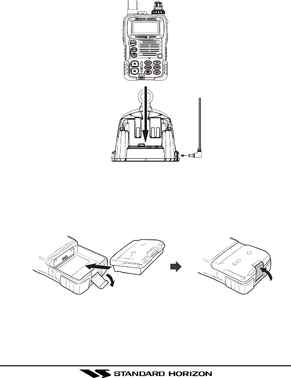
If the radio has never been used, or its charge is depleted, it may be charged
by connecting the CD-25 Charger Cradle with the NC-72 battery charger, as
shown in the illustration. If 12V DC power is available, the optional E-DC-19
DC Cable with 12 V Cigarette Lighter Plug or the optional E-DC-6 DC Cable
may be used for charging the battery. The NC-72, E-DC-19 and E-DC-6 will
charge a completely discharged FNB-80LI battery pack in about 3 hours.
4.1 BATTERIES AND CHARGERS
The FNB-80LI is a high performance Lithium-Ion battery providing high ca-
pacity in a very compact package.
CAUTION
To avoid risk of explosion and injury, FNB-80LI battery pack should only
be removed, charged or recharged in non-hazardous environments.
4.1.1 BATTERY SAFETY
Battery packs for your transceiver contain Lithium-Ion batteries. This type of
battery stores a charge powerful enough to be dangerous if misused or
abused, especially when removed from the transceiver. Please observe the
following precautions:
DO NOT SHORT BATTERY PACK TERMINALS: Shorting the terminals
that power the transceiver can cause sparks, severe overheating, burns,
and battery cell damage. If the short is of sufficient duration, it is possible to
melt battery components. Do not place a loose battery pack on or near metal
surfaces or objects such as paper clips, keys, tools, etc. When the battery
pack is installed on the transceiver, the terminals that transfer current to the
transceiver are not exposed. The terminals that are exposed on the battery
pack when it is mounted on the transceiver are charging terminals only and
do not constitute a hazard.
DO NOT INCINERATE: Do not dispose of any battery in a fire or incinerator.
The heat of fire may cause battery cells to explode and/or release danger-
ous gases.

HX470S Page 13
Battery Maintenance
For safe and proper battery use, please observe the following:
rBattery packs should be charged only in non-hazardous environments;
rUse only STANDARD HORIZON-approved batteries;
rUse only a STANDARD HORIZON, (a Marine Division of VERTEX
STANDARD) approved charger. The use of any other charger may
cause permanent damage to the battery.
rFollow charging instructions provided with the chargers.
rKeep the battery contacts clean.
Battery Storage
Store batteries in a cool place to maximize storage life. Since batteries are
subject to self-discharge, avoid high storage temperatures that cause large
self-discharge rates. After extended storage, a full recharge is recommended.
Battery Recycling
DO NOT PLACE USED BATTERIES IN YOUR REGULAR TRASH!
LITHIUM-ION BATTERIES MUST BE COLLECTED, RECYCLED OR DIS-
POSED OF IN AN ENVIRONMENTALLY SOUND MANNER.
The incineration, land filling or mixing of nickel-cadmium batteries with the
municipal solid waste stream is PROHIBITED BY LAW in most areas.
Return batteries to an approved lithium-ion battery recycler. This may be
where you purchased the battery.
Contact your local waste management officials for other information regarding
the environmentally sound collection, recycling and disposal of lithium-ion bat-
teries.
HX470SPage 14
4.1.2 BATTERY CHARGING
If the radio has never been used, or its charge is depleted, it may be charged
by connecting the CD-25 Charger Cradle with the NC-72 battery charger, as
shown in the illustration. If 12V DC power is available, the optional E-DC-19
DC Cable with 12 V Cigarette Lighter Plug or the optional E-DC-6 DC Cable
may be used for charging the battery. The NC-72, E-DC-19 and E-DC-6 will
charge a completely discharged FNB-80LI battery pack in about 3 hours.
NC-72,
E-DC-6,
or
E-DC-19
4.1.3 BATTERY INSTALLATION/REMOVAL
1. Turn the transceiver off.
2. To install, insert the battery pack into the battery compartment on the
back of the transceiver, then close the Battery Pack Latch until it locks in
place with a “click.”
3. To remove, open the Battery Pack Latch on the bottom of the trans-
ceiver, then slide the battery downward and out from the transceiver.
HX470S Page 15
4.1.4 USING THE CD-25 CHARGER CRADLE
1. Turn the transceiver off.
2. Insert the DC plug from the NC-72 into the DC jack on the CD-25 rear
panel, then plug the NC-72 into the AC line outlet.
3. Insert the HX470S (with the battery pack) into the CD-25; the antenna
should be at the left side when viewing the charger from the front.
4. If the HX470S is inserted correctly, the Red “CHARGING” indicator will
glow. A fully-discharged pack will be charged completely in approximately
3 hours.
5. The Red “CHARGING” indicator will blink when charging is nearing
completion.
6. When charging is completed, the Red “CHARGING” indicator will disap-
pear, and the Green “FULL” indicator will glow. Disconnect the pack from
the CD-25, and unplug the NC-72 from the AC line outlet.
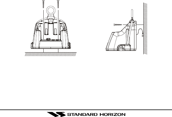
4.1.5 MOUNTING THE CD-25 ON THE VESSEL
The CD-25 is designed to be surface or wall mounted on a vessel which can
be connected to the charger and a GPS that supplies NMEA data for DSC
Distress transmissions.
If mounting on a vessel the CD-25 must be mounted in a location on the
vessel that is directly shielded from rain or splashes of water. After the loca-
tion is found mount the CD-25 using the supplied mounting screws.
CD-25 Desktop Mount CD-25 Wall Mount
HX470SPage 16
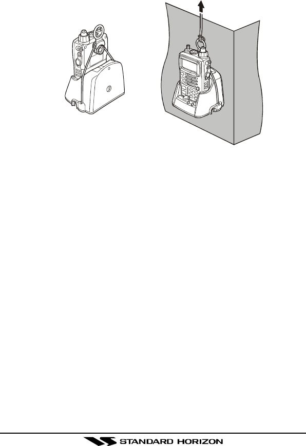
When using the HX470S/CD-25 on the vessel, be sure to secure the mount-
ing band on the CD-25 so that it secures the HX470S so it will not fall out
due to rough seas. See the illustration below.
HX470S Page 17
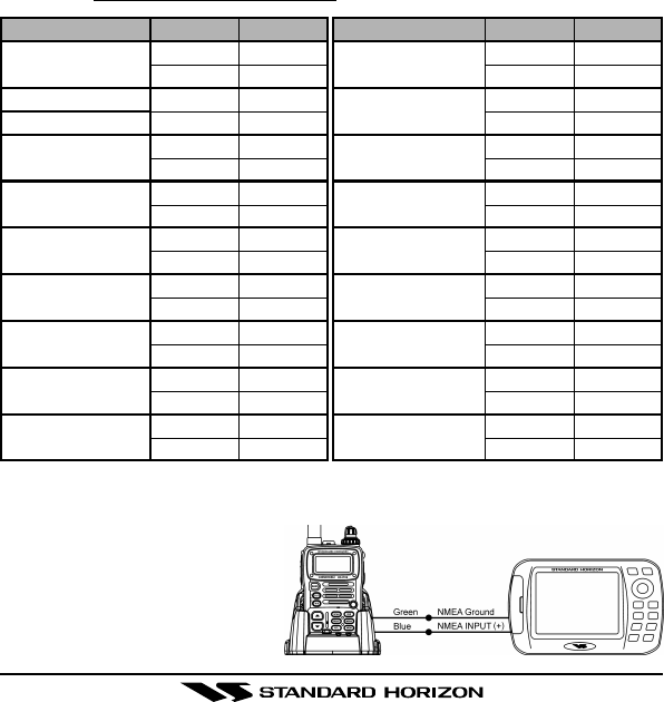
4.2 CONNECTING A GPS TO THE CD-25
The CD-25 is supplied with a cable that is designed to be connected to any
GPS that has an NMEA Output with the GLL, GGA, GNS, or RMC sen-
tences. Check with the owner’s manual of the GPS to confirm this informa-
tion. The NMEA input cable on the CD-25 contains two wires, uses are shown
below.
Blue – NMEA Input
(Connects to NMEA Out of GPS)
Green – NMEA Negative
(Connects to NMEA Negative or battery Ground of GPS)
If you have further inquires, please feel free to contact us at:
Phone: (800) 767-2450
Fax: (714) 527-9031
Web site: standardhorizon.com
Email: marinetech@vxstdusa.com
To connect to a GPS receiver, please use the above chart that will help you
connect the wires between the CD-25 and the GPS. Insure that the wires
are properly shielded from wa-
ter. See the figure at the right
for example of connection to
STANDARD HORIZON GPS
CHART PLOTTER.
Manufacturer/Model
Lowrance Portable
Magellan Fixed Mount
Magellan Portable
Northstar
Raytheon 420
Raytheon 520 / 620
Raytheon RL SERIES
Simrad
Sitex Neptune, Nautilus
Wires
Orange
Black (GND)
Gray
Black (GND)
Orange
Black (GND)
Yellow
Black (GND)
Yellow
Brown
Blue
Brown
White
Brown
White
Brown
Gray
Brown
HX470S (CD-25)
Blue
Green
Blue
Green
Blue
Green
Blue
Green
Blue
Green
Blue
Green
Blue
Green
Blue
Green
Blue
Green
Wires
Green
Brown
White
Blue
White
Black
Blue
Black (GND)
Brown
Black (GND)
Yellow
Green
Green
Black
White
Black
White
Black (GND)
Manufacturer/Model
Furuno GP30, 36
Furuno GP1650, 1850
Garmin Fixed Mounts
Garmin Portables
JRC GPS500
JRC 100 SERIES
JRC 200 SERIES
Lowrance Fixed Mount
HX470S (CD-25)
Green
Blue
Blue
Green
Blue
Green
Blue
Green
Blue
Green
Blue
Green
Blue
Green
Blue
Green
Blue
Green
STANDARD HORIZON
CP150, CP160 and
CP-170C
HX470SPage 18
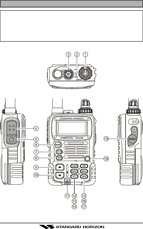
5. CONTROLS AND SWITCHES
NOTE
This section defines each control of the transceiver. For detailed oper-
ating instructions, refer to section 6 “BASIC OPERATION.” Refer to il-
lustrations for the location of the following controls, switches, and con-
nections.

HX470S Page 19
POWER SWITCH/VOLUME CONTROL
Turns the transceiver on and off, and adjusts the volume.
SQUELCH (SQL) CONTROL
Sets the point at which random noise on the channel does not activate
the audio circuits but a received signal does. This point is called the
Squelch threshold. Further adjustment of the squelch control will de-
grade the reception of wanted transmissions.
MIC/SP JACK
The jack accepts the optional CMP460 Speaker/Microphone, MH-57A4B
Mini Speaker/Microphone, or VC-24 VOX Headset. When this jack is
used, the internal speaker is disabled.
PUSH-TO-TALK (PTT) SWITCH
When pushed activates the transmitter of the selected band.
LAMP (KEY LOCK) KEY
Press to turn the LCD and keypad backlighting on or off.
Hold down this key to lock the keypad (except the PTT, LAMP, and [H/L]
keys) so that they are not accidentally changed. The key lock symbol will
appear on the LCD, to indicate that the functions are locked. Hold down
until the key lock symbol disappears to unlock the radio.
[BAND] KEY
Press to select the VHF Marine, FRS , MURS , FM Broadcast, AM Broad-
cast, and AIR (aircraft) bands.
[16/9] KEY
Immediately recalls channel 16 from any marine channel or band loca-
tion. Holding down this key recalls channel 9.
[WX] KEY
Immediately recalls the last-used NOAA Weather Channel from any chan-
nel location. Recalls the previously- selected working channel when the
[WX] key is pressed again.
Secondary use:
When the [16/9] key is held and the [WX] key is pressed, the radio will
change the marine channel between the USA, International, and Cana-
dian channels.

HX470SPage 20
[p(UP)] KEY
Press to select a desired channel. Each press increases the channel
number. When held down, the channels increase continuously.
[q(DOWN)] KEY
Press to select a desired channel. Each press decreases the channel
number. When held down, the channels decrease continuously.
NMEA TERMINAL
Connect to GPS receiver that outputs NMEA sentences GLL, GGA, GNS,
and RMC via the CD-25 Charger Cradle. Keep these terminals clean.
[SCAN] KEY
Starts scanning and priority scanning of programmed channels. When
scanning, press and hold this key to turn on and off priority scan (P is
shown on the left side of the display during Priority scanning).
[PRESET] KEY
Immediately recalls one of up to 10 user preset memories for each band
(shown as P0-P9 on the LCD). Pressing this key repeatedly scrolls
through the preset memory channels.
[H/L] KEY
On the Marine Band, changes the transmitter output power between High
(5 Watts), Medium (2.5 Watts), and Low (1 Watt). Does not operate on
“Low power only,” Marine “transmission inhibit,” or FRS channels.
[DW] KEY
Automatically scans between the priority channel and another selected
channel (including FRS or a MURS channel). When receiving a signal
on the selected channel the radio will dual watch to the priority channel.
[MENU] KEY
Select the Marine Band then press to select the Setup mode. This mode
allows features and functions to be changed.
Refer to section 13. MENU (“SET”) MODE for additional information.
HX470S Page 21
[MEM] KEY
Press this key to memorize the selected channel for scanning. When
pressed a “MEM” icon will be shown on the LCD display indicating the
channel has been saved to scan memory. The scan memory is only
used with the Marine and WX channels.
To delete the channel from scan memory, select the channel and press
this key until “MEM” is removed from the display.
BUSY/TX INDICATOR
This indicator illuminates different colors depending on the band that is
selected. The chart to the right shows
the colors illuminated with the Squelch
control fulluy counter clockwise or a sig-
nal is received. This indicator glows red
during transmit.
[DISTRESS] KEY
When radio is programmed with a MMSI and this key is pressed once
and pressed and held again for 3 seconds the radio will transmit a DSC
Distress Call. To send the distress call, see section 7.9 “DIGITAL SE-
LECTIVE CALLING.”
BAND COLOR
MARINE Blue
FRS Green
MURS Yellow
AM/FM/AIR/MURS Marine Blue