Yaesu Musen HX470SA Non-broadcast Transceiver Held to Face User Manual
Yaesu Musen Co., Ltd. Non-broadcast Transceiver Held to Face Users Manual
Contents
- 1. Manual Part 1
- 2. Manual Part 2
- 3. Manual Part 3
Manual Part 3
HX470SPage 22
6. BASIC OPERATION
6.1 INITIAL SETUP
1. Install the belt clip on the transceiver according to the description in the
box below, if desired.
2. Install the nylon carrying strap on the belt clip, if desired.
3. Install the battery pack on the transceiver (see section 4.1.3 “BATTERY
INSTALLATION/REMOVAL”).
NOTE: Water resistance of the transceiver is assured only when the
battery pack is attached to the transceiver and MIC/SP rubber cap is
installed in the MIC/SP jack.
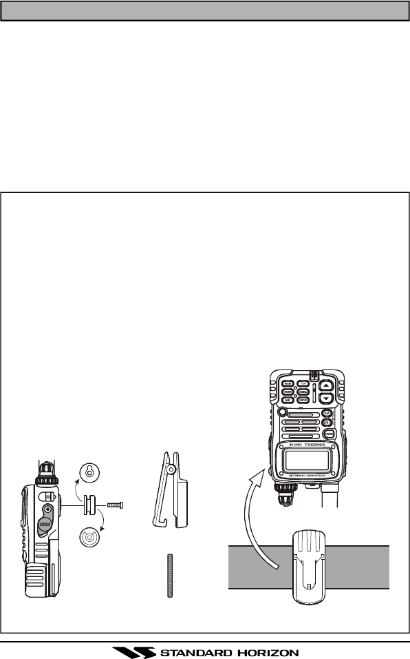
How to use the Quick Draw Belt Clip
1. Connect the hanger to the rear of the HX470S, with the notch
pointing directly up, using the supplied screw (Figure 1).
Use only the screw included with the clip to mount the clip to
the back of the transceiver!
2. Clip the Quick Draw Belt Clip to your belt (Figure 2).
3. To install the HX470S into the Quick Draw Belt Clip, align the
hanger with the Quick Draw Belt Clip and slide the HX470S into
its slot until a click is heard.
4. To remove the HX470S from the Quick Draw Belt Clip, rotate the
HX470S 180 degrees, then slide
the transceiver out from the Quick
Draw Belt Clip (Figure 3).
ñ
ò
Figure 3Figure 1 Figure 2
HX470S Page 23
6.2 RECEPTION
1. Turn the POWER/VOLUME CONTROL knob clockwise to turn the trans-
ceiver on.
2. Turn the SQUELCH CONTROL knob fully counterclockwise. This state
is known as “Squelch Off.”
3. Turn up the POWER/VOLUME CONTROL knob until the noise or audio
from the speaker is at a comfortable level.
4. Select the desired operating band among the VHF
Marine band, FRS band, MURS band, FM band,
AM band, and AIR band by pressing the [BAND]
key repetitively to switch between the bands.
5. Turn the squelch control fully to the left so au-
dio is heard.
6. Press the [p] or [q] key to select a channel or
frequency that has no signal being received
(no one is transmitting on the channel)
7. Slowly turn the SQUELCH CONTROL knob clockwise and stop immedi-
ately after the noise disappears. This condition is known as the “Squelch
Threshold.” If the knob is turned clockwise past this point, weak signals
may not be received. No noise or no signal is heard until a signal is
received that exceeds the squelch threshold. Sometimes, a slight ad-
justment of the squelch threshold is needed, as some channels have a
higher noise level than others.
8. Press the [SCAN] key momentarily; the HX470S will begin scanning to-
ward a higher channel or frequency and will stop when it receives a
signal strong enough to break through the squelch threshold. Press the
[SCAN] key momentarily to channel the scanning. Refer to section 7.2
for programming channels into scan memory.
9. Please refer to section 16 for VHF Marine and section 3 for FRS and
MURS channel assignments.
10. If necessary, press the LAMP key to turn on the display illumination. The
lamp automatically turns off in about 5 seconds.
11. To “lock” the channel so that it is not accidentally changed, hold down
the LAMP key for about three seconds. This locks the [p] and [q] keys
and all the front panel controls except the [H/L], PTT and LAMP keys.
The “ ” symbol will appear on the display to indicate that the keypad
is locked. Hold down the LAMP key for about one second to unlock the
keys. The “ ” symbol will disappear from the display..

HX470SPage 24
6.3 TRANSMISSION
1. Perform steps 1 through 7 of the RECEPTION discussion above.
2. Before transmitting, monitor the channel and make sure it is clear.
THIS IS AN FCC REQUIREMENT!
3. For communications over short distances on the Marine band, press the
[H/L] key until “L” is displayed on the LCD. This indicates Low power
(approximately 1 watt).
Note
Transmitting on 1 watt prolongs battery life. Low power (1 watt)
should be selected whenever possible. On the FRS band, the
transmit power is fixed (0.5 Watt).
4. If using Low power is not effective, select Medium power (2.5 watts) or
High power (5 watts) by pressing the [H/L] key until “M” (Medium power)
or “H” (High power) is displayed.
5. When receiving a signal, wait until the incoming signal stops before trans-
mitting. The transceiver cannot transmit and receive simultaneously.
6. Press the PTT (Push-To-Talk) switch to transmit. The “TX” indicator is
displayed during transmission.
7. Speak slowly and clearly into the microphone. Hold the microphone about
1/2 to 1 inch away from your mouth.
8. When the transmission is finished, release the PTT switch.
For an overview of VHF Marine and FRS band operating procedures refer to
section 3.
6.3.1 TRANSMIT TIME - OUT TIMER (TOT)
While the PTT switch is held down, transmission time is limited to 5 minutes.
This prevents prolonged (unintentional) transmissions. About 10 seconds
before automatic transmitter shutdown, a warning beep sounds from the
speaker. The transceiver automatically switches to the receiving mode, even
if the PTT switch is held down. Before transmitting again, the PTT switch
must first be released, and then pressed again. This Time-Out-Timer (TOT)
prevents a continuous transmission that would result from an accidentally
stuck PTT switch.

HX470S Page 25
6.4 NOAA WEATHER CHANNELS
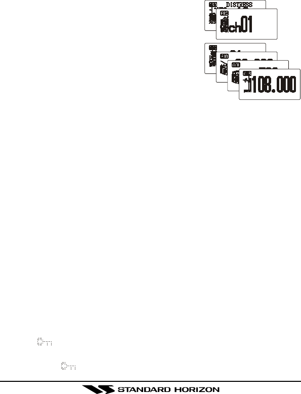
1. To receive a NOAA weather broadcast, press the [WX] key. The trans-
ceiver changes to the weather channel mode.
This mode consists of a special preset memory
bank containing the NOAA weather channels.
2. The transceiver will be set to the last used NOAA
weather channel. Press the [p] or [q] key to change to other weather
channels.
3. To exit from the weather channel mode, press the [WX] key. The trans-
ceiver will revert to the channel you were using prior to switching to the
weather channel mode.
6.4.1 NOAA WEATHER ALERT
In the event of extreme weather disturbances such as storms and hurri-
canes, NOAA (National Oceanic and Atmospheric Administration) sends a
“weather alert” consisting of a 1050 Hz tone, followed by weather reports on
the weather channels. The transceiver is capable of receiving this alert if the
following is performed:
1. Program your area’s weather channels into the transceiver’s scan
memory. Follow the same procedure as for regular channels.
2. Press the [SCAN] key to start the scan.
3. The memorized weather channels are scanned along with the regular
memorized channels. Scanning will not stop on the (continuous) weather
broadcast channels unless the weather alert tone is received.
4. When an alert is received on a weather channel, scanning stops and the
transceiver emits a beeping tone that will stay on for 5 minutes.
5. Press the [WX] key to listen to the Weather Alert.

HX470SPage 26
6.5 PRESET CHANNELS (P0 ~ P9): INSTANT ACCESS
Ten user assigned channels can be programmed for instant access. Press-
ing the [PRESET] key activates the user assigned channel bank. If the [PRE-
SET] key is pressed and no channels have been assigned, an alert beep
will be emitted twice from the speaker.
The HX470S provides the ten Preset channel for each individual operating
band (VHF Marine, FRS, MURS, AM Broadcast, FM Broadcast and Air Band).
Programming
1. Select the desired band by pressing the [BAND] key.
2. Hold down the [PRESET] key, and press the [p] or [q] key (repeatedly,
if necessary) until the desired channel number or frequency is displayed.
3. With the desired number displayed, release the [PRESET] key.
4. Repeat steps 2 and 3 to program the desired channels into Preset Chan-
nels “P1” ~ “P9.”
5. To delete a Preset Channel, hold down the [PRESET] key and press the
[p] or [q] key until the Preset Channel number to be deleted is dis-
played, then release the [PRESET] key.
You may add an alpha-numeric name “Tag” to any desired Preset Channel;
refer to CH NAME SET item on the section 13 “MENU (“SET”) MODE.”
Operation
Pressing the [PRESET] key will toggle between Preset Channels “P0” - “P9”
and the last selected “regular” channel. Preset Chan-
nel “P0” is represented by “P0” to the left of the chan-
nel number on the LCD, and preset channel “P1” is
represented by “P1” and so forth.
Press the [SCAN] key while on any of the Preset Channels, the HX470S will
begin scanning the Preset Channels of the selected band.

HX470S Page 27
6.6 ENABLING S.O.S STROBE OPERATION
The S.O.S. STROBE feature utilizes the high-intensity strobe LED on the
front of the HX470S as a visual distress beacon. When enabled, the LED
blinks the internationally-recognized Morse Code “S.O.S.” message
(•••–––•••) at a rate of 5 words per minute. This can be very useful in
summoning help from rescuers who may not be able to communicate with
you via radio.
1. Hold down the [MEM] key while turning the radio on to activate the emer-
gency S.O.S. Strobe. Once the radio comes on, the BUSY/TX LED will
flash the Morse Code S.O.S. message repeatedly.
2. The S.O.S. strobe function is interrupted when a signal is received or if
the squelch control is turned so audio is heard from the speaker. and
during transmission.
3. To disable the S.O.S. strobe function, turn the radio off and back on
again.
HX470SPage 28
7. ADVANCED OPERATION ON THE MARINE BAND
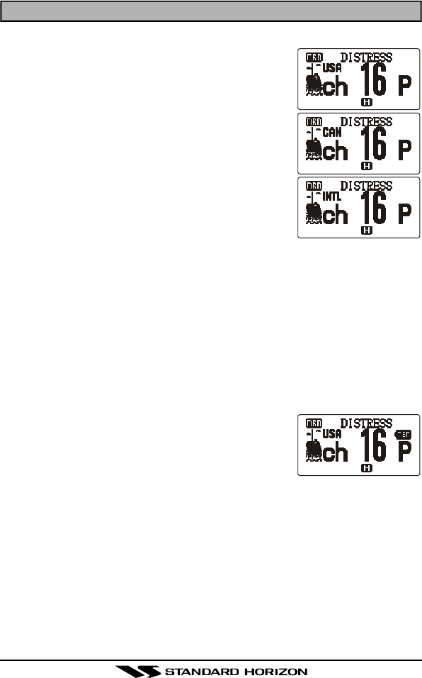
7.1 USA, CANADIAN, AND INTERNATIONAL CHANNELS
1. To change from US to Canadian or International
Marine Channels, hold down the [16/9] key and
press the [WX] key. The band will change from
USA, to International, and to Canadian with each
press.
2. “USA” appears on the LCD for the USA band,
“CAN” appears for the Canadian band, and
“INTL” appears for the International band.
3. Refer to the marine channel charts in section 16
“VHF MARINE CHANNEL ASSIGNMENTS” for
allocated channels.
7.2 MEMORY SCAN
The HX470S can be programmed to scan channels from a minimum of 2
channels up to all channels in the marine band. If an incoming signal is
detected on one of the channels during scan, the radio will pause on that
channel, allowing you to listen to the incoming transmission.
Select the desired band (VHF Marine, FRS, MURS, AM Broadcast, FM Broad-
cast or Air Band) on which you wish to select channels to be scanned.
1. Select the desired channel to be included in the scan memory using the
[p] or [q] key.
2. Press the [MEM] key to store the channel into
the transceiver’s scan memory. “MEM” will be
displayed on the LCD.
3. Repeat steps 1 and 2 for all the channels to be
scanned.
4. To delete a channel from the transceiver’s scan memory, select the memo-
rized channel. Press the [MEM] key until “MEM” is removed from the
display.
5. All channels programmed remain in the transceiver’s scan memory even
if the power is turned off. See section 11 “RESETTING THE
TRANSCEIVER’S MICROPROCESSOR” to clear all channels from the
transceiver’s scan memory.
6. Adjust the SQUELCH CONTROL knob until background noise is elimi-
nated.

HX470S Page 29
7. To start scanning, press the [SCAN] key. The scan proceeds from the
lowest to the highest programmed channel and stops scanning when a
transmission is received. Scanning will resume when the incoming sig-
nal disappears at the end of the transmission. A small “SCAN” icon is
shown on the center bottom of the display during scanning.
8. To stop the scan, press the [SCAN] key.
7.3 PRIORITY SCAN
The priority scanning feature allows the radio to scan while also keeping
watch on a particularly important “priority channel.” The following channels
can be set as the priority channel: 16, 09, and MARINE Preset Channel.
1. To set the priority channel, hold down the [16/9] key and press the [MEM]
key. The channel will change from 16 to 09 to Preset Channels P0 through
P9 with each press of the [MEM] key. When the
[16/9] key is released the displayed channel will
be set as the priority channel (the large “P” icon
will appear at the right side of the channel num-
ber).
2. For priority scanning, hold down the [SCAN] key during normal scan-
ning. Scanning will proceed between the memorized channels and the
priority channel. The priority channel will be scanned after each pro-
grammed channel. A small “PSCN” is shown on the center bottom of the
display during priority scanning.
3. As an example of priority scanning, let us say that marine channels 06,
07, and 08 are memorized in the transceiver’s scan memory. Priority
scanning will proceed in the following sequence:
[CH06] à [Priority Channel] à [CH07] à [Priority Channel] à
[CH08] à [Priority Channel] à [CH06] à [Priority Channel] ……
4. Even when the transceiver stops and listens to the signal of a programmed
channel, the transceiver will shift to a “dual watch” mode between this
channel and the priority channel. Therefore, your priority watching of the
designated channel is not compromised when the scanner has paused
on an active channel.
5. Hold down the [SCAN] key to change the priority scanning to normal
scanning, and then press the [SCAN] key to stop the scan and return to
normal operation.

HX470SPage 30
7.4 DUAL WATCH
The Dual Watch feature allows the radio to watch for a transmission on the
priority channel and another selected Marine, FRS or MURS channel until a
signal is received. The priority channel is determined per the discussion in
section 7.3 “PRIORITY SCAN” as described previously.
1. To start the Dual Watch feature, select a channel to be dual watched
with the priority channel and press the [DW] key.
The radio checks the priority channel for voice
traffic every one second. A small “DW” icon is
shown on the center bottom of the display dur-
ing scanning.
2. To cancel the Dual Watch feature, press the [DW] key.
7.5 EMERGENCY CHANNEL 16
1. To select the emergency channel, press the [16/9] key from any chan-
nel.
2. If you cannot contact anyone on channel 16, switch to another channel.
3. See section 10.1 “EMERGENCY (CHANNEL 16 USE)” for additional
emergency operating practices.
4. To recall the previously-used channel when you are finished on channel
16, press the [16/9] key again.
7.6 CHANNEL 9
Channel 9 is used as a hailing channel for initial, non-emergency contacts
with other vessels. Hold down the [16/9] key for 1 second to select channel
9. You should change to a working channel, after contact is established (so
as to keep the hailing channel clear for other users).
7.7 OPERATING ON USA OR CANADIAN 13, OR USA CHANNEL 67
USA and Canadian Channel 13, USA 67 are used at docks, bridges and for
maneuvering in port. Messages on this channel must concern navigation
only, such as meeting and passing in restricted waters. In emergencies and
when approaching blind river bends, high power is allowed. Holding down
the [H/L] key will change the power output from 1 Watt (L) to 5 Watts (H); if
pressed and held again 2.5 Watts (M) will be selected. When the PTT switch
is released, the transceiver will revert to low power. Press and hold in the [H/
L] key again if you need High power on a subsequent transmission.

HX470S Page 31
7.8 OPERATING ON USA CHANNEL 67
USA Channel 67 is used for navigational bridge-to-bridge traffic between
ships. This channel has been allocated for temporary high power transmis-
sion if communication is not able to be established on one watt.
Select Channel 67, then press the [H/L] key to set the transmitter output to
either High or Medium power. When the PTT switch is released, the trans-
ceiver will revert to low power.
7.9 DIGITAL SELECTIVE CALLING
7.9.1 GENERAL
7.9.1.1 Digital Selective Calling (DSC)
Digital Selective Calling is a semi-automated method of establishing a radio
call; it has been designated by the International Maritime Organization (IMO)
as an international standard for establishing VHF, MF and HF radio calls. It
had also been designated as part of the Global Maritime Distress and Safety
System (GMDSS). It is planned that DSC will eventually replace aural watches
on distress frequencies and will be used to announce routine and urgent
maritime safety information broadcasts.
The HX470S has a DSC Distress feature that allows mariners to instantly
transmit a VHF Marine distress call with GPS position (when connected to
the transceiver) to the US Coast Guard and other vessels within range of
the transmission.
7.9.1.2 Maritime Mobile Service Identity (MMSI)
What is an MMSI?
An MMSI is a nine digit number used on Marine Transceivers capable of
using Digital Selective Calling (DSC). This number is used by the HX470S
when a Marine DSC Distress call is transmitted. This number is registered
with the USCG. Refer to section 13 “MENU (“SET”) MODE”(MMSI REG).
NOTE: An MMSI must be programmed into the HX470S before the DSC
Distress function will operate. If you have a fixed mounted DSC VHF and
already have a MMSI, this MMSI should be programmed into the HX470S.
How can I obtain a MMSI assignment?
Currently there are two companies that offer MMSI numbers:
¦Boat US at (800) 563-1539 or visit the web site http://www.boatus.com/mmsi/.
¦Seatow at (631) 765-3660 or visit the web site http://www.seatow.com/
mmsiinfo.htm

HX470SPage 32
WARNING: This radio is designed to generate a digital maritime distress
and safety call to facilitate search and rescue. To be effective as a safety
device, this equipment must be used only within communication range of a
shore-based VHF marine channel 70 distress and safety watch system.
7.9.2 SENDING A DISTRESS CALL
The distress call automatically includes the vessel’s DSC MMSI and Lat/
Lon position. The vessel’s position will only be transmitted if the transceiver
is properly connected to an operating GPS receiver with NMEA output.
1. Lift the red DISTRESS rubber cover on the right side of the transceiver
and press the [DISTRESS] key. “DSC DISTRESS” will appear on the
top of the LCD.
2. Press and hold in the [DISTRESS] key for 3 seconds. The LCD will count
down (3s, 2s, 1s), and afterwards the HX470S will transmit the DSC
Distress Call on channel 70.
3. When the distress signal is being sent, “TX” icon will appear on the LCD.
After the message has been sent, the Distress Alarm will sound.
4. The transceiver “shadow-watches” for a transmission between CH16 and
CH70 until an acknowledgment signal is received.
5. If no acknowledgment is received, the distress call is repeated in three
minute intervals until an acknowledgment is received.
6. To cancel the distress call alarm, press the [16/9] key.
7. To send the CANCEL call:
Press the [DISTRESS] key, then press the [p] or [q] key until “CAN-
CEL” is shown on the LCD. Press the [DISTRESS] key.
NOTE: When a GPS receiver with NMEA output is connected via the CD-25
Charger Cradle, the vessel’s position is automatically transmitted with the
distress call. The HX470S will remember the position input from the GPS
until the radio is turned off.
7.10 SIMPLEX/DUPLEX CHANNEL USE
All Marine channels are factory-programmed in accordance with FCC (USA),
Industry Canada and International regulations. The mode of operation can-
not be altered from simplex to duplex or vice-versa. Simplex (ship to ship) or
duplex (marine operator) mode is automatically activated, depending on the
channel and whether the USA, International or Canadian operating band is
selected.

HX470S Page 33
8. CTCSS OPERATION ON THE FRS BANDS
8.1 CTCSS CODE OPERATION
CTCSS stands for Continuous Tone Coded Squelch System; it is a sub-
audible tone system with 39 selections, labeled CODE01 through CODE39.
CTCSS tones are used on FRS channels where there are several stations
transmitting on the same frequencies within close proximity to one another.
When this occurs, you may hear multiple communications at the same time
to the point where it is impossible to clearly receive and understand the
transmission of the person calling you.
The HX470S allows you to program CTCSS codes for each FRS channel. If
multiple signals are transmitted on the channel you selected, you will only
hear the transmission of other stations with the same CTCSS tone that was
programmed in the HX470S. If the radio does not receive the correct tone
on the selected channel, then you will not hear the transmission.
1. Select the FRS channel on which you wish to utilize CTCSS control of
the squelch.
2. Press the [MENU] key to enter the Menu Mode.
3. Press the [p] or [q] key to select Menu item (CTCSS).
4. Press the [MENU] key to enable adjustment of this Menu item (“CTCSS”
icon will blink).
5. Press the [p] or [q] key to select the desired CTCSS code number
(CODE01 - CODE39).
6. Press the [MENU] key to save the new setting.
7. Press the PTT key to exit from the Menu mode, and activate the CTCSS
feature.
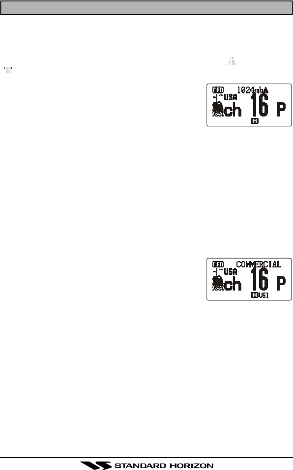
When CTCSS is programmed the CTCSS code
number will appear to the right of the operating chan-
nel number.
To disable CTCSS operation, select “OFF” in step 5
above.
CODE FREQUENCY
01 67.0 Hz
02 71.9 Hz
03 74.4 Hz
04 77.0 Hz
05 79.7 Hz
06 82.5 Hz
CODE FREQUENCY
07 85.4 Hz
08 88.5 Hz
09 91.5 Hz
10 94.8 Hz
11 97.4 Hz
12 100.0 Hz
CODE FREQUENCY
13 103.5 Hz
14 107.2 Hz
15 110.9 Hz
16 114.8 Hz
17 118.8 Hz
18 123.0 Hz
CODE FREQUENCY
19 127.3 Hz
20 131.8 Hz
21 136.5 Hz
22 141.3 Hz
23 146.2 Hz
24 151.4 Hz
CODE FREQUENCY
25 156.7 Hz
26 162.2 Hz
27 167.9 Hz
28 173.8 Hz
29 179.9 Hz
30 186.2 Hz
CODE FREQUENCY
31 192.8 Hz
32 203.5 Hz
33 210.7Hz
34 218.1 Hz
35 225.7 Hz
36 233.6 Hz
CODE FREQUENCY
37 241.8 Hz
38 250.3 Hz
39 69.3 Hz
– –
– –
– –
HX470SPage 34
9. BAROMETER AND SCRAMABLER OPERATION
9.1 BAROMETRIC PRESSURE METER
The optional Barometric Pressure unit (SU-1) brings to the HX470S the
unique capability of providing readout of the current barometric pressure
and display the relative changes in the pressure (Upward ( ) or Downward
(), Count: every 1/2 hour). The SU-1 unit requires calibration of the “off-
set” parameters, so that the pressure reading will
be correct. To do this you must have a barometer to
use as a reference as you adjust the SU-1 to match
its reading; see section 13 “MENU (“SET”)
MODE”(BARO OFFSET).
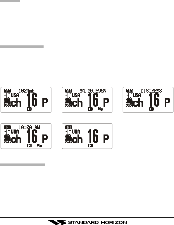
To display the current barometric pressure:
1. Press the [MENU] key to enter the Menu Mode.
2. Press the [p] or [q] key to select the Menu item (DISPLAY MODE).
3. Press the [MENU] key to enable adjustment of this Menu item.
4. Press the [p] or [q] key to set this Menu item to “BARO.”
5. When you have completed your selection, press the [MENU] key to save
the new setting, and then press the PTT key to exit to normal operation.
6. To disable the barometric pressure display, select “None” in step 4 above.
9.2 VOICE SCRAMBLER UNIT
The optional FVP-31 Voice Scrambler Unit permits
secure voice communications with stations within
your network, which prevents others from listening
using normal communication equipment.
To activate the Voice Scrambler:
1. Select the channel on which you wish to activate the Voice Scrambler.
2. Press the [MENU] key to enter the Menu Mode.
3. Press the [p] or [q] key to select the Menu item (SCRAMBLER).
4. Press the [MENU] key to enable adjustment of this Menu item.
5. Press the [p] or [q] key to set this Menu item to “ON.”
6. When you have completed your selection, press the [MENU] key to save
the new setting, and then press the PTT key to exit to normal operation.
7. To disable the Voice Scrambler, select “OFF” in step 5 above.
Note: Voice Scrambler may not be activated on Marine Channels 16 and
70.

HX470S Page 35
10. OPERATING PRACTICES
10.1 EMERGENCY (CHANNEL 16 USE)
Channel 16 is known as the Hail and Distress Channel. An emergency may
be defined as a threat to life or property. In such instances, be sure the
transceiver is on and set to CHANNEL 16. Then use the following proce-
dure:
1. Press the microphone push-to-talk switch and say “Mayday, Mayday,
Mayday. This is , , ” (your vessel’s name).
2. Then repeat once: “Mayday, ” (your vessel’s name).
3. Now report your position in latitude/longitude, or by giving a true or mag-
netic bearing (state which) to a well-known landmark such as a naviga-
tion aid or geographic feature such as an island or harbor entry.
4. Explain the nature of your distress (sinking, collision, aground, fire, heart
attack, life-threatening injury, etc.).
5. State the kind of assistance your desire (pumps, medical aid, etc.).
6. Report the number of persons aboard and condition of any injured.
7. Estimate the present seaworthiness and condition of your vessel.
8. Give your vessel’s description: length, design (power or sail), color and
other distinguishing marks. The total transmission should not exceed 1
minute.
9. End the message by saying “OVER”. Release the microphone button
and listen.
10. If there is no answer, repeat the above procedure. If there is still no
response, try another channel.
10.2 CALLING ANOTHER VESSEL (CHANNEL 16 OR 9)
Channel 16 may be used for initial contact (hailing) with another vessel.
However, its most important use is for emergency messages. This channel
must be monitored at all times except when actually using another channel.
It is monitored by the U.S. and Canadian Coast Guards and by other ves-
sels. Use of channel 16 for hailing must be limited to initial contact
only. Calling should not exceed 30 seconds, but may be repeated 3 times at
2-minute intervals. In areas of heavy radio traffic, congestion on channel 16
resulting from its use as a hailing channel can be reduced significantly in
U.S. waters by using Channel 9 as the initial contact (hailing) channel for
non-emergency communications. Here, also, calling time should not exceed
30 seconds but may be repeated 3 times at 2-minute intervals.

HX470SPage 36
Prior to making contact with another vessel, refer to the channel charts in
this manual, and select an appropriate channel for communications after
initial contact. For example, Channels 68 and 69 of the U.S. VHF Charts are
some of the channels available to non-commercial (recreational) boaters.
Monitor your desired channel in advance to make sure you will not be inter-
rupting other traffic, and then go back to either channel 16 or 9 for your initial
contact.
When the hailing channel (16 or 9) is clear, state the name of the other
vessel you wish to call and then “this is” followed by the name of your ves-
sel and your Station License (Call Sign). When the other vessel returns your
call, immediately request another channel by saying “go to,” the number of
the other channel, and “over.” Then switch to the new channel. When the
new channel is not busy, call the other vessel.
After a transmission, say “over,” and release the microphone’s push-to-talk
(PTT) switch. When all communication with the other vessel is completed,
end the last transmission by stating your Call Sign and the word “out.” Note
that it is not necessary to state your Call Sign with each transmission, only
at the beginning and end of the contact.
Remember to return to Channel 16 when not using another channel. Some
radios automatically monitor Channel 16 even when set to other channels
or when scanning; see your Owner’s Manual.
10.3 OPERATING ON CHANNELS 13 AND 67
Channel 13 is used at docks and bridges and by vessels maneuvering in
port. Messages on this channel must concern navigation only, such as meet-
ing and passing in restricted waters.
Channel 67 is used for navigational traffic between vessels.
By regulation, power is normally limited to 1 Watt on these channels. Your
radio is programmed to automatically reduce power to this limit on these
channels. However, in certain situations it may be necessary to temporarily
use a higher power. See page 20 ([H/L] key) for means to temporarily over-
ride the low-power limit on these two channels.

HX470S Page 37
10.4 PROHIBITED COMMUNICATIONS
The FCC prohibits the following communications:
•False distress or emergency messages:
•Messages to “any boat” except in emergencies and radio tests;
•Messages to or from a vessel on land;
•Transmission while on land;
•Obscene, indecent, or profane language (potential fine of $10,000).
10.5 NOAA WEATHER ALERT TESTING
In the event of a major storm or other appreciable weather condition requir-
ing vessels at sea (or other bodies of water) to be notified, the NOAA (Na-
tional Oceanographic and Atmospheric Administration) broadcasts a 1050
Hz tone that some VHF radios, including your HX470S, can detect for
“Weather Alarm” purposes (refer to section 6.4.1 “NOAA WEATHER ALERT”
for a discussion of how to use this feature). The 1050 Hz tone, when de-
tected, will produce a loud beep in the speaker of the HX470S, to signal that
a Weather Alert Broadcast is being received.
In order to test this system, NOAA broadcasts the 1050 Hz tone every
Wednesday sometime between 11 AM and 1 PM local time. You may use
this opportunity to test your HX470S periodically to confirm that the Weather
Alert feature is working, or for training crew members on how to configure
the HX470S to receive the NOAA Weather Alerts.

HX470SPage 38
11. RESETTING THE TRANSCEIVER’S MICROPROCESSOR
Resetting the microprocessor restores the initial, factory-supplied conditions
in the transceiver. These are called the “default” conditions.
To reset the microprocessor, first turn the transceiver off. Then, while press-
ing and holding in the [WX] and [SCAN] keys, turn the transceiver on.
The default conditions are:
•No channel numbers are in scan memory.
•Channel 16 is the priority channel.
•Channel 16 will be selected when the transceiver is turned on.
•WX channel 01 will be recalled when the [WX] key is pressed.
•Preset Channels are unassigned.
Note: The above procedure also resets the microprocessor. Perform this
procedure if an operational problem occurs which cannot be solved by nor-
mal operating procedures.

HX470S Page 39
12. CLONING
The HX470S includes a convenient “Clone” feature, which allows the memory
and configuration data from one transceiver to be transferred to another
HX470S.
Turn both radios off.
1. Connect the (optional) CT-32 Clone Cable between the MIC/SP jacks of
the two transceivers.
2. Hold down the [PRESET] key and then turn on the transceiver. Do this
for both transceivers (the order of switching the radios on does not mat-
ter); “CLONE” will appear on the display on both transceivers.
3. On the Destination transceiver, press the [MEM] key (“CLONE RX” will
appear on the LCD).
4. Press the [16/9] key on the Source transceiver; “CLONE TX” will appear
on the Source radio, and the data will now be transferred.
5. If there is a problem during the cloning process, “CLONE ERR” is dis-
played. Check your cable connections and battery voltage, and try again.
6. If the data transfer is successful, the Destination transceiver will return
to normal operation; Turn both transceivers off and disconnect the Clone
cable. You can then turn the transceivers back on, and begin normal
operation.
HX470SPage 40
13. MENU (“SET”) MODE
The HX470S’s Menu Mode allows a number of the HX470S operating pa-
rameters to be custom-configured for your operating requirements.
The Menu Mode is easy to activate and set, using the following procedure:
1. Press the [MENU] key to enter the Menu Mode.
2. Press the [p] or [q] key to select the Menu item to be adjusted.
3. Press the [MENU] key to enable adjustment of the selected Menu item.
The menu item will blink
4. Press the [p] or [q] key to select the status or value of the Menu item.
5. After completing your adjustment, press the PTT key to save the new
setting and exit to normal operation.
BEEP
Function: Enable/Disable the Keypad beeper.
Available Values: ON / OFF
Default: ON
BARO OFFSET (Requires optional SU-1)
Function: Calibrating the Barometric Pressure meter.
Press the [p] or [q] key to set the HX470S’s Barometric Pressure display to
match a Calibrated Barometer’s displayed pressure.
Available Values: –127 to +127
Default: 000
BARO UNIT (Requires optional SU-1)
Function: Selects the Units Of Measure of the Barometric display.
Available Values: mb / HPA / mm Hg / Inches
Default: mb
CH NAME SET
Function: Changes the channel name shown on the display.
1. Select the channel on which you wish to change the name before recall-
ing this Menu item.
2. Press the [MENU] key to enter the Menu Mode.
3. Press the [p] or [q] key to select this Menu item (CH NAME SET).
4. Press the [MENU] key to enable adjustment of this Menu item.
5. Press the [p] or [q] key to select the first character (letter, number, or
symbol) in the name you wish to change, then press the [MEM] key to
move to the next character.
HX470S Page 41
6. If you make a mistake, press the [H/L] key to move back, and then reselect
the correct letter, number, or symbol.
7. Repeat step 5 as many times as necessary to complete the name tag
(up to 10 characters).
8. After completing your adjustment, press the [MENU] key to save the
new setting.
9. Press the PTT key to exit to normal operation.
CTCSS
Function: Enables/Disables CTCSS operation and allows code selection
Available Values: ON (with 39 standard CTCSS Tones) / OFF
Default: OFF
Note: This Menu Item is only selectable on the FRS band (you may only
access this Menu Item while operating on the FRS band).
DISPLAY MODE
Function: Selects the information to be displayed on the LCD
Available Values: BAROø1 / GPS NAV infoø2 / CH name / Timeø2 / None
Default: CH name
ø1: Requires optional SU-1
ø2: Requires GPS receiver.
DISTRESS RING
Function: Selects how long the DSC Distress alarm will ring
Available Values: 3 min / 5 times / 10 times / 15 times
Default: 3 min
GPS NAV Info
BARO CH name
NoneTime
HX470SPage 42
DW DISPLAY
Function: Selects the Dual Watch scanning display mode.
Available Values: Normal / Special
Default: Special
When “Special” is selected the channel shown on the display is the last
channel the HX470S received a call on. This is a handy feature if you cannot
look at the radio the moment a transmission was received
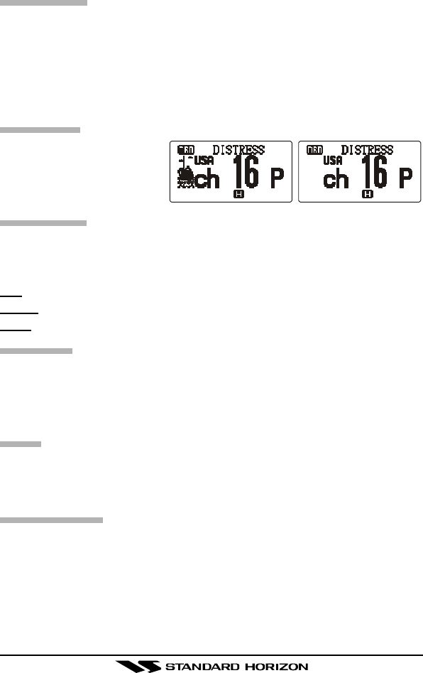
BAND ICON
Function: Enable/Disable
the BAND Icon display
Available Values: ON / OFF
Default: ON
LAMP MODE
Function: Selects the Lamp illumination method for the LCD/Keypad.
Available Values: Key / Toggle / 5 sec
Default: Key
Key: Illuminates the LCD/Keypad for 5 seconds when any key is pressed.
Toggle: Pressing the LAMP key toggles the LCD/Keypad lamp On/Off.
5 sec: Pressing the LAMP key illuminates the LCD/Keypad for 5 seconds.
MMSI REG
Function: Stores MMSI ID code.
Note: The MMSI can only be inputted twice. If entered more than twice, the
HX470S will have to be sent to STANDARD HORIZON factory service to
reset the MMSI.
MUTE
Function: Enable/Disable the Audio Muting on the FM Broadcast Band.
Available Values: ON / OFF
Default: ON
SCAN DISPLAY
Function: Selects the Scanning display mode
Available Values: Normal / Special
Default: Normal
When this menu is set to “Normal,” the channel numbers during scan will be
shown as scrolling on the display. When Special is selected the channel
numbers on the display do not change unless a call was received. The chan-
nel shown is the last channel that was received.
BAND ICON “OFF”BAND ICON “ON”

HX470S Page 43
SCAN LAMP
Function: Enable/Disable the automatic illumination of the lamp when a
signal is received on a channel during Scanning
Available Values: ON / OFF
Default: OFF
SCRAMBLER (Requires optional FVP-31)
Function: Enable/Disable the Voice scrambler.
Available Values: ON / OFF
Default: OFF
Note: This Menu Item is ignored when using Marine Channels 16 and 70.
STEP
Function: Selects the AM Band frequency step size
Available Values: 10kHz or 9kHz (for Europe)
Default: 10kHz
STROBE
Function: Selects the DSC Distress Call STROBE illumination
Available Values: OFF / Flashing / Continue / SOS
Default: OFF
TIME OFFSET
Function: Allows entering a “Time Offset” for your location so the time will
be shown correctly on the display when connected to a GPS receiver via the
CD-25 Charger Cradle.
Available Values: –12 to +12
Default: 00
WX ALERT
Function: Enable/Disable the Weather Alert feature.
Available Values: ON / OFF
Default: ON

HX470SPage 44
14. MAINTENANCE
14.1 GENERAL
The inherent quality of the solid-state components in STANDARD HORI-
ZON radios will provide many years of continuous use. Take the following
precautions to prevent damage to the radio.
rKeep the microphone connected or the jack covered at all times to pre-
vent corrosion of electrical contacts;
rNever key the transmitter unless an antenna or suitable dummy load is
connected to the antenna receptacle.
rEnsure that the input voltage does not exceed the value specified in your
Owner’s Manual.
rUse only STANDARD HORIZON-approved accessories and replacement
parts.
14.2 REPLACEMENT PARTS
Occasionally an owner needs a replacement parts. These can be ordered
from our Parts Department by writing or calling:
Marine Division of Vertex Standard
US Headquarters
10900 Walker Street, Cypress, CA 90630, U.S.A.
Telephone (714) 827-7600
Commonly requested parts, and their part numbers are listed below.
•VOLUME Knob: RA0474200
•SQL Knob: RA0474100
•CD-25 Charger Cradle: Q7000462
•MIC/SP Cover: RA0399700
•DISTRESS Cover: RA0474800
HX470S Page 45
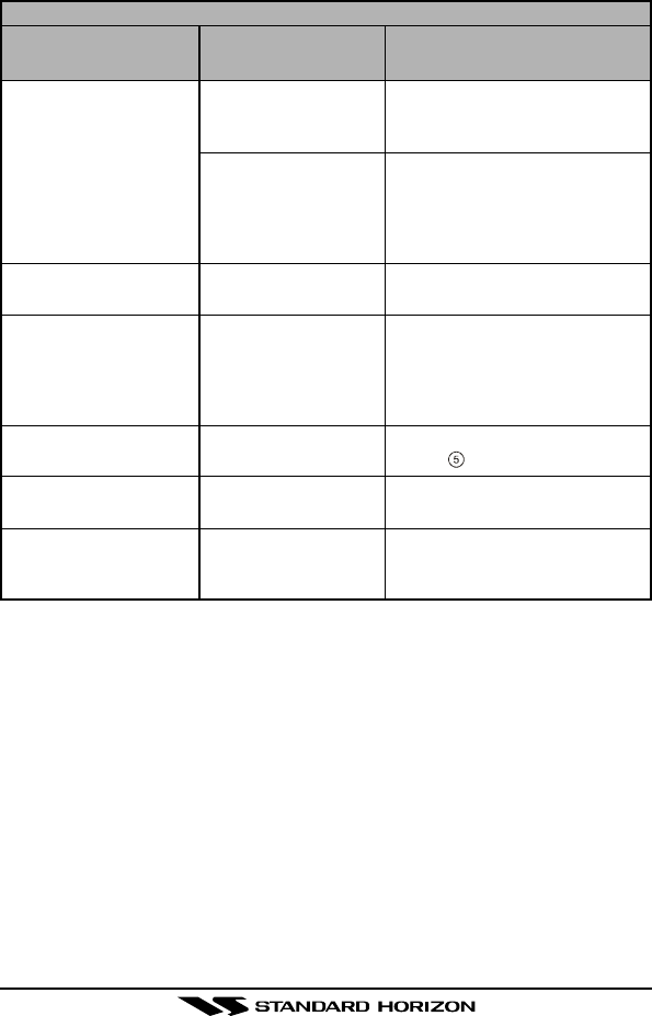
TROUBLESHOOTING CHART
SYMPTON
The [SCAN] key does
not start the scan.
The USA/INTL/CAN
modes do not function.
Rotating the
SQUELCH CONTROL
knob does not
eliminate background
noise.
Cannot change any
function.
Key Lock does not
function.
Indicator does not light
when charging a
battery.
PROBABLE
CAUSE
No channels
memorized.
Squelch is not
adjusted.
Proper operation not
followed.
Low battery.
Key Lock is on.
Proper operation not
followed.
Defective battery
FNB-80LI.
REMEDY
Use the MEM key to enter de-
sired channels into the
transceiver’s memory.
Adjust the squelch to threshold
or to the point where noise just
disappears. Further adjustment
of the squelch control may elimi-
nate incoming signals.
HOLD down the 16/9 key and
press the WX key.
Charge battery. Refer to section
5 of this manual.
Turn Key Lock off. Refer to sec-
tion 5, LAMP key..
Hold down the LAMP key for 1
second.
Contact your Standard Horizon
dealer.
14.3 TROUBLESHOOTING CHART
HX470SPage 46
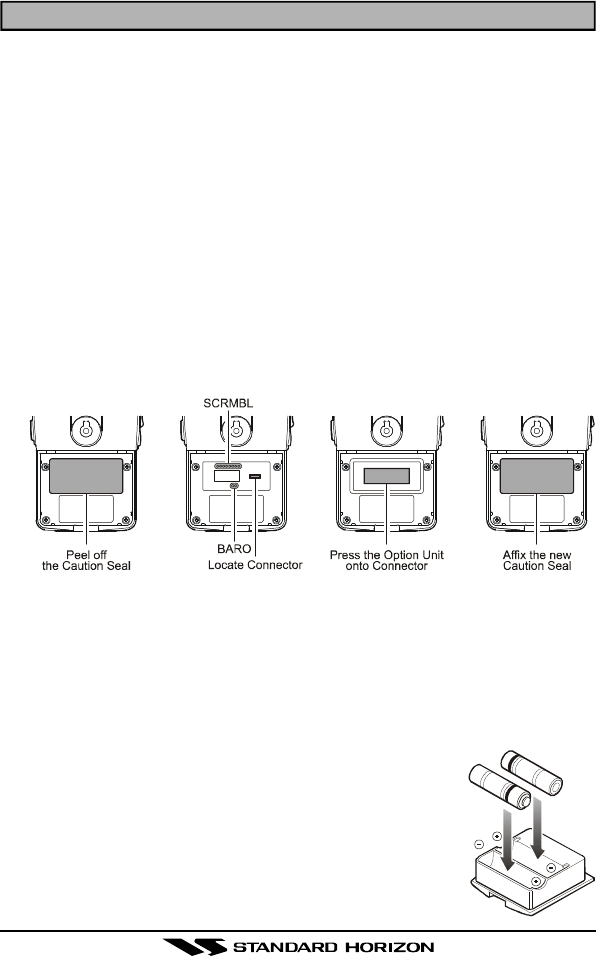
15. INSTALLATIONS OF OPTION
15.1 SU-1 BAROMETRIC PRESSURE UNIT OR
FVP-31 VOICE SCRAMBLER UNIT
1. Make sure that the transceiver is off. Remove the hard or soft case, if
used. Remove the battery pack.
2. Locate the connector for the optional unit under the caution seal in the
battery compartment on the back of the radio; just peel off the caution seal.
3. When installing the Barometric Pressure Unit SU-1, connect the jumper
pads labeled “BARO” (2 pair) by soldering them together. When install-
ing the Voice Scrambler Unit FVP-31, connect the jumper pads labeled
“SCRMBL” (8 pair) using the soldering jumper.
Note: It is not possible to install both optional units into the same radio.
4. Align the connector on the optional unit with the transceiver’s connector
and gently press the unit into place.
5. Affix the new caution seal (supplied with the optional unit), and replace
the battery. Installation is now complete.
â
â
â
15.2 FBA-23 BATTERY CASE
FBA-23 is a battery case that holds two alkaline batteries and is used with
the HX470S transceiver. Alkaline batteries can be used for transmission in
an emergency, but power output is reduced to one watt, and battery life will
be short.
1. Slide the batteries into the FBA-23 with the Negative [–] side of the batter-
ies touching the spring connections inside the FBA-23.
2. Insert the FBA-23 into the battery compartment on the
back of the transceiver, then close the Battery Pack
Latch until it locks in place with a “click.”
Note: The battery indicator on the transceiver is only ap-
plicable to the FNB-80LI rechargeable battery. Disregard
this indication when using alkaline batteries.

HX470S Page 47
16. VHF MARINE CHANNEL ASSIGNMENTS
Tables on the following pages list the VHF Marine Channel assignments for
U.S.A. and International use. Below are listed some data about the charts.
1. VTS. Where indicated, these channels are part of the U.S. Coast Guard’s
Vessel Traffic System.
2. Alpha channel numbers, that is, channel numbers followed by the letter
A (such as Channel 07A) are simplex channels on the U.S.A. or Cana-
dian channel assignments whose counterparts in the International as-
signments are duplex channels. International channels do not use “al-
pha” numbers. If you call the Coast Guard on Channel 16, they will some-
times ask you to “go to channel 22 Alpha.” This is a channel assigned
to U.S.A, and Canadian Coast Guards for handling distress and other
calls. If your radio is set for International operation you will go to Chan-
nel 22 instead of 22A, and will not be able to communicate with the
Coast Guard. To use Channel 22A, your radio must be set for USA or
Canada operation, using the USA/CAN/INTL channel selection proce-
dure described on page 28 of this manual. Channel 22 (without an “A”) is
an International duplex channel for port operations. The HX470S dis-
plays an “A” adjacent to the channel number on all “Alpha” channels,
unlike some other models that may not indicate the “A” even though they
may be set to the correct frequency.
3. Bridge-to-Bridge channels (for example, Channel 13) are for use by bridge
operators on inter-coastal waterways and rivers. It is also used by ma-
rine vessels in the vicinity of these bridges for navigation and for com-
municating with the bridge operators. Note that a limit of 1 Watt is speci-
fied for these channels.
4. The S/D column on the chart indicates either S (simplex) or D (duplex).
Simplex means transmitting and receiving on the same frequency. Only
one party at a time can talk, unlike a telephone. Be sure to say “over”
and release your microphone push-to-talk switch at the end of each trans-
mission. Duplex operation involves the use of one frequency for trans-
mitting and a separate frequency for receiving. On channels specified
as duplex on the charts, correct mode of operation is established auto-
matically by your radio when you select a channel; you cannot change
the mode. And you still must release the push-to-talk switch after each
transmission in order to listen to the radio.
5. Channels normally used by recreational boaters are those that include
HX470SPage 48
the term “non-commercial” in the Channel Use column of the chart. Some
of these are shared with other users and some are used only in certain
geographic regions.
6. Marine vessels equipped with VHF radios are required to monitor
Channel 16.
VHF Marine Channel
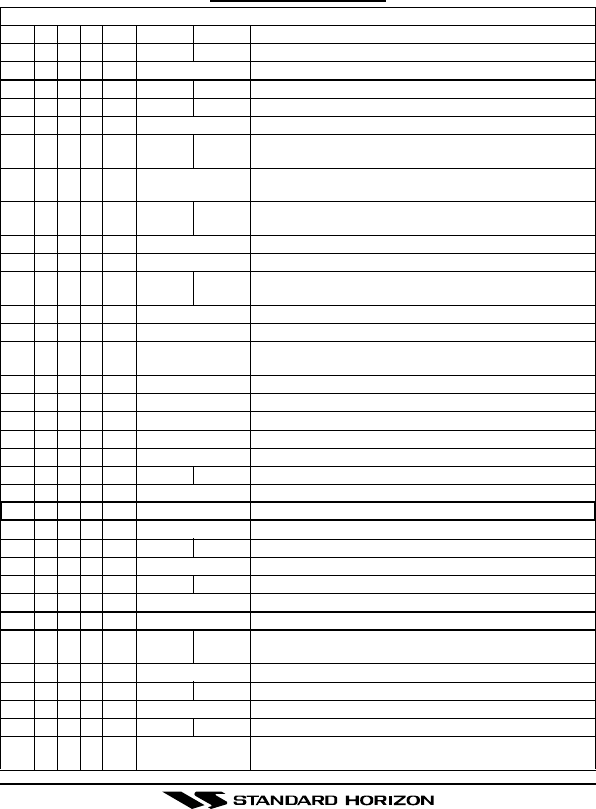
VHF MARINE CHANNEL CHART
CH U C IS/D TX RX CHANNEL USE
01 X X D156.050 160.650 Public Correspondence (Marine Operator)
01A X S 156.050 Port Operation and Commercial. VTS in selected areas
02 X X D156.100 160.700 Public Correspondence (Marine Operator)
03 X X D156.150 160.750 Public Correspondence (Marine Operator)
03A X S 156.150 US Government only, Coast Guard
04 XD156.200 160.800 Public Correspondence (Marine Operator),
Port operation, ship movement
04A X S 156.200 Pacific coast: Coast Guard, East Coast:
Commercial fishing
05 XD156.250 160.850 Public Correspondence (Marine Operator),
Port operation, ship movement
05A X X S 156.250 Port operation. VTS in Seattle
06 X X X S 156.300 Inter-ship Sefety
07 XD156.350 160.950 Public Correspondence (Marine Operator),
Port operation, ship movement
07A X X S 156.350 Commercial
08 X X X S 156.400 Commercial (Inter-ship only)
09 X X X S 156.450 Boater Calling channel, Commercial & Non-commercial
(Recreational)
10 X X X S 156.500 Commercial
11 X X X S 156.550 Commercial. VTS in selected areas.
12 X X X S 156.600 Port operation. VTS in selected areas.
13 X X X S 156.650 Inter-ship Navigation Safety (Bridge-to-bridge)
14 X X X S 156.700 Port operation. VTS in selected areas.
15 X S - - - 156.750 Environmental (Receive only)
15 X X S 156.750 Commercial, non-commercial, ship movement (1 W)
16 X X X S 156.800 International Distress, Safety and Calling
17 X X X S 156.850 State Controlled (1 W)
18 XD156.900 161.500 Port operation, ship movement
18A X X S 156.900 Commercial
19 XD156.950 161.550 Port operation, ship movement
19A X S 156.950 US: Commercial
19A X S 156.950 Coast Guard
20 X X X D157.000 161.600 Canadian Coast Guard Only,
International: port operations and shipment
20A X S 157.000 Port operation
21 XD157.050 161.650 Port operation, ship movement
21A X X S 157.050 U.S. Government Only, Canadian Coast Guard
22 XD157.100 161.700 Port operation, ship movement
22A X X S 157.100 US and Canadian Coast Guard Liaison and Maritime
Safety Information Broadcasts announced on channel 16

HX470S Page 49
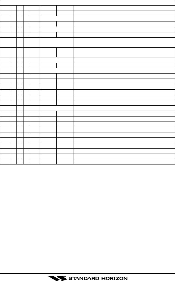
VHF MARINE CHANNEL CHART
CH U C IS/D TX RX CHANNEL USE
23 X X D157.150 161.750 Public Correspondence (Marine Operator)
23A X S 157.150 U.S. Government Only
24 XXX D157.200 161.800 Public Correspondence (Marine Operator)
25 XXX D157.250 161.850 Public Correspondence (Marine Operator)
26 XXX D157.300 161.900 Public Correspondence (Marine Operator)
27 XXX D157.350 161.950 Public Correspondence (Marine Operator)
28 XXX D157.400 162.000 Public Correspondence (Marine Operator)
60 X X D156.025 160.625 Public Correspondence (Marine Operator)
61 XD156.075 160.675 Public Correspondence (Marine Operator),
Port operation, ship movement
61A X X S 156.075 U.S. Government Only, Canadian Coast Guard-
Pacific Coast, Commercial Fishing-East Coast
62 XD156.125 160.725 Public Correspondence (Marine Operator),
Port operation, ship movement
62A X S 156.125 Public Coast: Coast Guard;
East Coast: commercial fishing only
63 XD156.175 160.775 Public Correspondence (Marine Operator),
Port operation, ship movement
63A X S 156.175 Port Operation and Commercial. VTS in selected areas.
64 X X D156.225 160.825 Public Correspondence (Marine Operator),
Port operation, ship movement
64A X X S 156.225 U.S. Government Only, Canadian Commercial Fishing
65 XD156.275 160.875 Public Correspondence (Marine Operator),
Port operation, ship movement
65A X X S 156.275 Port Opeations
66 XD156.325 160.925 Public Correspondence (Marine Operator),
Port operation, ship movement
66A X X S 156.325 Port Operations
67 X X X S 156.375 US: Commercial. Used for Bridge-to-bridge communi-
cations in lower Mississippi River. Inter-ship only,
Canada: Commercial fishing, S&R
68 X X X S 156.425 Non-commercial (Recreational)
69 X X X S 156.475 US: Non-commercial (Recreational),
Canada: Commercial fishing only,
International: Inter-ship, Port opertions and Ship movement
70 X X X S 156.525 Digital selective calling (voice communications not allowed)
71 X X X S 156.575 US, Canada: Non-commercial (Recreational),
International: Port opertions and Ship movement
72 X X X S 156.625 Non-commercial (Inter-ship only)
73 X X X S 156.675 US: Port Operations, Canada: Commercial fishing only,
International: Inter-ship, Port opertions and Ship movement
74 X X X S 156.725 US: Port Operations, Canada: Commercial fishing only,
International: Inter-ship, Port opertions and Ship movement
75 X S 156.775 Port Operations (Inter-ship only) (1W)
76 X S 156.825 Port Operations (Inter-ship only) (1W)
77 X X S 156.875 Port Operations (Inter-ship only) (1W)
77 X S 156.875 Port Operations (Inter-ship only)
78 XD156.925 161.525 Public Correspondence (Marine Operator),
Port operation, ship-movement
78A X X S 156.925 Non-commercial (Recreational)
HX470SPage 50
VHF MARINE CHANNEL CHART
CH U C IS/D TX RX CHANNEL USE
79 XD156.975 161.575 Port operation and Ship movement
79A X X S 156.975 Commercial
80 XD157.025 161.625 Port operation, ship movement
80A X X S 157.025 Commercial
81 XD157.075 161.675 Port operation, ship movement
81A X X S 157.075 U.S. Government Only -
Environmental protection operations.
82 XD157.125 161.725 Public Correspondence (Marine Operator),
Port operation, ship movement
82A X X S 157.125 U.S. Government Only, Canadian Coast Guard Only
83 X X D157.175 161.775 Canadian Coast Guard Only
83A X X S 157.175 U.S. Government Only, Canadian Coast Guard Only
83 X X D157.175 161.775 Public Correspondence (Marine Operator)
84 X X X D157.225 161.825 Public Correspondence (Marine Operator)
85 X X X D157.275 161.875 Public Correspondence (Marine Operator)
86 X X X D157.325 161.925 Public Correspondence (Marine Operator)
87 X X X D157.375 161.975 Public Correspondence (Marine Operator)
88 X X X D157.425 162.025 Public Correspondence (ship-to-coast)
88A X S 157.425 Commercial, Inter-ship Only
WX01
X X X D- - - 162.550 Weather (receive only)
WX02
X X X D- - - 162.400 Weather (receive only)
WX03
X X X D- - - 162.475 Weather (receive only)
WX04
X X X D- - - 162.425 Weather (receive only)
WX05
X X X D- - - 162.450 Weather (receive only)
WX06
X X X D- - - 162.500 Weather (receive only)
WX07
X X X D- - - 162.525 Weather (receive only)
WX08
X X X D- - - 161.650 Weather (receive only)
WX09
X X X D- - - 161.775 Weather (receive only)
WX10
X X X D- - - 163.275 Weather (receive only)
The above BOLD channels are not for use of the general public in U.S. waters, unless proper
authorization is given.
HX470S Page 51
1: 156.050 MHz and 156.175 MHz are available for port operations and commercial communications
purposes when used only within the U.S. Coast Guard designated Vessel Traffic Services (VTS)
area of New Orleans, on the lower Mississippi River from the various pass entrances in the Gulf of
Mexico to Devil's Swamp Light at River Mile 242.4 above head of passes near Baton Rouge.
2: 156.250 MHz is available for port operations communications use only within the U.S. Coast Guard
designated VTS radio protection areas of New Orleans and Houston described in Sec. 80.383.
156.250 MHz is available for intership port operations communications used only within the area of
Los Angeles and Long Beach harbors, within a 25- nautical mile radius of Point Fermin, California.
3: 156.550 MHz, 156.600 MHz and 156.700 MHz are available in the U.S. Coast Guard designated
port areas only for VTS communications and in the Great Lakes available primarily for communica-
tions relating to the movement of ships in sectors designated by the St. Lawrence Seaway Develop-
ment Corporation or the U.S. Coast Guard. The use of these frequencies outside VTS and ship
movement sector protected areas is permitted provided they cause no interference to VTS and ship
movement communications in thier respective designated sectors.
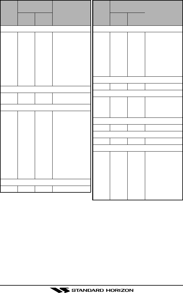
Port Operations
01A1156.050 156.050
63A1156.175 156.175
052156.250 156.250
65A 156.275 156.275
66A 156.325 156.325
123156.600 156.600
73 156.675 156.675
143156.700 156.700
74 156.725 156.725
774156.875 Intership only.
20A12 157.000 Intership only.
Navigational (Bridge-to-Bridge)5
136156.650 156.650
677156.375 156.375
Commercial
01A1156.050 156.050
63A1156.175 156.175
07A 156.350 156.350
677156.375 Intership only.
08 156.400 ........ Do.
09 156.450 156.450
10 156.500 156.500
113156.550 156.550
18A 156.900 156.900
19A 156.950 156.950
79A 156.975 156.975
80A 157.025 157.025
88A8157.425 ........ Intership only.
7214 156.625 ........ Internship only.
Digital Selective Calling
7015 156.525 156.525
Noncommercial
6817 156.425 156.425
0916 156.450 156.450
69 156.475 156.475
71 156.575 156.575
72 156.625 ........ Intership only.
78A 156.925 156.925
79A 156.975 156.975 Great Lakes only.
80A 157.025 157.025 Do.
6714 156.375 ....... Internship only.
Distress, Safety and Calling
16 156.800 156.800 EPRIB
Intership Safety
06 156.300 ........ a. Intership, or b.
For SAR: Ship and
aircraft for the U.S.
Coast Guard.
Environmental
1513 ........ 156.750 Coast to ship only.
Maritime Control
179,10 156.850 156.850
Liaison, U.S. Coast Guard
22A11 157.100 157.100 Ship, aircraft, and
coast stations of
the U.S. Coast
Guard and at Lake
Mead, Nev., ship
and coast stations
of the National
Park Service, U.S.
Department of the
Interior.
Ship
transmit
Channel
designator
Carrier frequency
(
MHz
)
Points of communica-
tion
(
Intership and be-
tween coast and ship
unless otherwise indi-
cated
)
Coast
transmit Ship
transmit
Channel
designator
Carrier frequency
(
MHz
)
Points of communica-
tion
(
Intership and be-
tween coast and ship
unless otherwise indi-
cated
)
Coast
transmit

HX470SPage 52
4: Use of 156.875 MHz is limited to communications with pilots regarding the movement and docking
of ships. Normal output power must not exceed 1 watt.
5: 156.375 MHz and 156.650 MHz are available primarily for intership navigational communications.
These frequencies are available between coast and ship on a secondary basis when used on or in
the vicinity of locks or drawbridges. Normal output power must not exceed 1 watt. Maximum output
power must not exceed 10 watts for coast stations or 25 watts for ship stations.
6: On the Great Lakes, in addition to bridge-to-bridge communications, 156.650 MHz is available for
vessel control purposes in established vessel traffic systems. 156.650 MHz is not available for use in
the Mississippi River from South Pass Lighted Whistle Buoy “2” and Southwest Pass entrance
Midchannel Lighted Whistle Buoy to mile 242.4 above Head of Passes near Baton Rouge. Addition-
ally it is not available for use in the Mississippi River-Gulf Outlet, the Mississippi River-Gulf Outlet
Canal, and the Inner Harbor Navigational Canal, except to aid the transition from these areas.
7: Use of 156.375 MHz is available for navigational communications only in the Mississippi River from
South Pass Lighted Whistle Buoy “2” and Southwest Pass entrance Mid-channel Lighted Whistle
Buoy to mile 242.4 above head of Passes near Baton Rouge, and in addition over the full length of
the Mississippi River-Gulf Outlet Canal from entrance to its junction with the Inner Harbor Navigation
Canal, and over the ull length of the Inner Harbor Navigation Canal from its junction with the Missis-
sippi River to its entry to Lake Pontchartrain at the New Seabrook vehicular bridge.
8: Within 120 km (75 miles) of the United States/Canada border, in the area of the Puget Sound and
the Strait of Juan de Fuca and its approaches, 157.425 MHz is half of the duplex pair designated as
Channel 88. In this area, Channel 88 is available to ship stations for communications with public
coast stations only. More than 120 km (75 miles) from the United States/Canada border in the area
of the Puget Sound and the Strait of Juan de Fuca, its approaches, the Great Lakes, and the St.
Lawrence Seaway, 157.425 MHz is available for intership and commercial communications. Outside
Puget Sound area and its approaches and the Great Lakes, 157.425 MHz is also available for
communications between commercial fishing vessels and associated aircraft while engaged in com-
mercial fishing activities.
9: When the frequency 156.850 MHz is authorized, it may be used additionally for search and rescue
training exercises conducted by state or local governments.
10: The frequency 156.850 MHz is additionally available to coast stations on the Great Lakes for trans-
mission of scheduled Coded Marine Weather Forecasts (MAFOR), Great Lakes Weather Broadcast
(LAWEB) and nscheduled Notices to Mariners or Bulletins. F3C and J3C emissions are permitted.
Coast Stations on the Great Lakes must cease weather broadcasts which cause interference to
stations operating on 156.800 MHz until the interference problem is resolved.
11: The frequency 157.100 MHz is authorized for search and rescuetraining exercises by state or local
government in conjunction with U.S. Coast Guard stations. Prior U.S. Coast Guard approval is re-
quired. Use must cease immediately on U.S. Coast Guard request.
12: The duplex pair for channel 20 (157.000/161.600 MHz) may be used for ship to coast station com-
munications.
13: Available for assignment to coast stations, the use of which is in accord with an agreed program, for
the broadcast of information to ship stations concerning the environmental conditions in which ves-
sels operate, i.e., weather; sea conditions; time signals; notices to mariners; and hazards to naviga-
tion.
14: Available only in the Puget Sound and the Strait of Juan de Fuca.
15: The frequency 156.525 MHz is to be used exclusively for distress, safety and calling using digital
selective calling techniques. No other uses are permitted.
16: The frequency 156.450 MHz is available for intership, ship and coast general purpose calling by
noncommercial vessels, such as recreational boats and private coast stations.
17: The frequency 156.425 MHz is assigned by rule to private coast stations in Alaska for facsimile
transmissions as well as voice communications.

HX470S Page 53
17. WARRANTY
Marine Products Limited Warranty
STANDARD HORIZON (a division of VERTEX STANDARD) warrants, to the origi-
nal purchaser only, each new Marine Communications Product (“Product”) manu-
factured and/or supplied by STANDARD HORIZON against defects in materials
and workmanship under normal use and service for a period of time from the
date of purchase as follows:
Fixed Mount and Portable Transceivers
1 year - if purchased before 01/01/91
3 years - if purchased between 01/01/91 and 01/01/94
3 years Waterproof - if purchased after 01/01/94
Loud hailers
1 year - if purchased before 01/01/91
3 years - if purchased after 01/01/91
Associated Chargers
1 year - if purchased before 01/01/91
3 years - if purchased after 01/01/91
Associated Batteries - 18 months. Note: Batteries will be deemed defective
only if storage capacity drops below 80% of rated capacity or if leakage devel-
ops.
Associated Accessories - 1 year. Includes: Microphones/Handsets, External
Speakers, Antennas, Carrying Accessories, Power Supplies, and Signaling
Boards.
To receive warranty service, the purchaser must deliver the Product, transporta-
tion and insurance prepaid, to STANDARD HORIZON (a division of VERTEX
STANDARD), 115 North Wright Brothers Dr, Salt Lake City, Utah 84116-2838.
Include proof of purchase indicating model. serial number, and date of purchase.
STANDARD HORIZON will return the Product to the purchaser freight prepaid.
Products purchased prior to January 1, 1991 will bear the STANDARD HORI-
ZON warranty terms in effect prior to that date.
In the event of a defect, malfunction or failure of the Product during the warranty
period, STANDARD HORIZON’s liability for any breach of contract or any breach
of express or implied warranties in connection with the sale of Products shall be
limited solely to repair or replacement, at its option, of the Product or part(s)
therein which, upon examination by STANDARD HORIZON, appear to be defec-
tive or not up to factory specifications. STANDARD HORIZON may, at its option,
repair or replace parts or subassemblies with new or reconditioned parts and
subassemblies. Parts thus repaired or replaced are warranted for the balance of
the original applicable warranty.

HX470SPage 54
STANDARD HORIZON will not warrant installation, maintenance or service of
the Products. In all instances, STANDARD HORIZON’s liability for damages shall
not exceed the purchase price of the defective Product.
This warranty only extends to Products sold within the 50 States of the United
States of America and the District of Columbia.
STANDARD HORIZON will pay all labor to repair the product and replacement
parts charges incurred in providing the warranty service except where purchaser
abuse or other qualifying exceptions exist. The purchaser must pay any trans-
portation expenses incurred in returning the Product to STANDARD HORIZON
for service.
This limited warranty does not extend to any Product which has been subjected
to misuse, neglect, accident, incorrect wiring by anyone other than STANDARD
HORIZON, improper installation, or subjected to use in violation of instructions
furnished by STANDARD HORIZON, nor does this warranty extend to Products
on which the serial number has been removed, defaced, or changed. STAN-
DARD HORIZON cannot be responsible in any way for ancillary equipment not
furnished by STANDARD HORIZON which is attached to or used in connection
with STANDARD HORIZON’s Products, or for the operation of the Product with
any ancillary equipment, and all such equipment is expressly excluded from this
warranty. STANDARD HORIZON disclaims liability for range, coverage, or op-
eration of the Product and ancillary equipment as a whole under this warranty.
STANDARD HORIZON reserves the right to make changes or improvements in
Products, during subsequent production, without incurring the obligation to in-
stall such changes or improvements on previously manufactured Products.
The implied warranties which the law imposes on the sale of this Product are
expressly LIMITED, in duration, to the time period specified above. STANDARD
HORIZON shall not be liable under any circumstances for consequential dam-
ages resulting from the use and operation of this Product, or from the breach of
this LIMITED WARRANTY, any implied warranties, or any contract with STAN-
DARD HORIZON. IN CONNECTION WITH THE SALE OF ITS PRODUCTS,
STANDARD HORIZON MAKES NO WARRANTIES, EXPRESS OR IMPLIED
AS TO THE MERCHANTABILITY OR FITNESS FOR A PARTICULAR PURPOSE
OR OTHERWISE, EXCEPT AS EXPRESSLY SET FORTH HEREIN.
Some states do not allow the exclusion or limitation of incidental or consequen-
tial damages, or limitation on how long an implied warranty lasts, so the above
limitations or exclusions may not apply. This warranty gives specific legal rights,
and there may be other rights which may vary from state to state.
ONLY PRODUCTS SOLD ON OR AFTER JANUARY 1, 1991 ARE COVERED
UNDER THE TERMS OF THIS LIMITED WARRANTY.

HX470S Page 55
ON-LINE WARRANTY REGISTRATION
THANK YOU for buying STANDARD HORIZON (a division of Vertex
Standard) products! We are confident your new radio will serve your
needs for many years!
Please visit www.standardhorizon.com to register the HX470S Marine
VHF. It should be noted that visiting the Web site from time to time may
be beneficial to you, as new products are released they will appear on
the STANDARD HORIZON Web site. Also a statement regarding prod-
uct support should be added to the manual.
Product Support Inquiries
If you have any questions or comments regarding the use of the HX470S,
you can visit the STANDARD HORIZON Web site to send an E-mail or
contact the Product Support team at 714/827-7600 ext 6300 M-F 7:00-
5:00PST.
In addition to the warranty, STANDARD HORIZON includes a lifetime
“flat rate” program to provide service after the warranty period has ex-
pired. If you wish to obtain the flat rate price for out-of-warranty repair,
you must include the information on the Owner’s Record with the unit
when you return it to your Dealer or to STANDARD HORIZON.
Lifetime Flat Rate Service Program: For the original Owner only, for the
lifetime of the unit, STANDARD HORIZON will repair the unit to original
specifications.
Note: The flat rate amount is payable by the Owner only if STANDARD
HORIZON or the STANDARD HORIZON Dealer determines that a re-
pair is needed. After the repair, a 90-day warranty will be in effect from
the date of return of the unit to the Owner.
This service program is not available for equipment which has failed as
a result of neglect, accident, breakage, misuse, improper installation or
modification, or water damage (depending on the product).

HX470SPage 56
18. SPECIFICATIONS
Performance specifications are nominal, unless otherwise indicated, and
are subject to change without notice.
18.1 GENERAL
Frequency Ranges (MHz): 156 MHz - 163.275 MHz
(Marine Band + WX Band)
Channel Steps: 25 kHz
462.5625 MHz - 467.7125 MHz
(FRS Band)
Channel Steps: 6.25 kHz
151.82 MHz - 154.60 MHz
(MURS)
Channel Steps: 5 kHz
88 MHz - 108 MHz
(FM Broadcast)
Channel Steps: 100 kHz
500 kHz - 1800 kHz
(AM Broadcast)
Channel Steps: 10 / 9 kHz
108 MHz - 137 MHz
(AIR Band)
Channel Steps: 25 kHz
Frequency Stability:±2.5 ppm
(–22 °F to +140 °F [–30 °C to +60 °C])
Emission Type:16K0G3E, 11K0F3E, 16K0G2B
Antenna Impedance:50 Ohms
Supply Voltage:Nominal: 7.4V DC, Negative Ground
(Battery Terminal)
Current Consumption:195 mA (Receive)
68 mA (Standby, Saver Off)
45 mA (Standby, Saver On)
1.7 A (Marine High Power)
1.2 A (Marine Mid Power)
0.8 A (Marine Low Power & FRS)
Operating Temperature:–22 °F to +140 °F (–30 °C to +60 °C)
Case Size (W x H x D): 2.36” x 3.78” x 1.12” (60 x 96 x 29 mm)
w/o knob & antenna
Weight (Approx.): 9.3 oz. (265 g) with FNB-80LI

HX470S Page 57
18.2 TRANSMITTER
RF Power Output (@7.4 V): 5, 2.5 or 1 W (Marine Band)
0.5W (FRS Band)
Modulation Type:Variable Reactance
Maximum Deviation:±5 kHz (Marine Band)
±2.5 kHz (FRS Band)
Spurious Emission:At least 65 dB below
Microphone Impedance:2 k-Ohm
18.3 RECEIVER
Circuit Type:Double-Conversion Superheterodyne
(NFM, AM)
Triple-Conversion Superheterodyne
(WFM)
Intermediate Frequencies:NFM, AM WFM
1st: 47.25 MHz 45.8 MHz
2nd: 450 kHz 10.7 MHz
3rd: –1 MHz
Sensitivity:0.2 µV for 12 dB SINAD
(Marine & MURS Band)
0.2 µV for 12 dB SINAD
(FRS Band)
1 µV for 12 dB SINAD
(FM Broadcast)
0.5 µV for 10 dB SN
(AM Broadcast)
0.5 µV for 10 dB SN
(AIR Band)
Adjacent Channel Selectivity:65 dB Typical
Intermodulation:65 dB Typical
Selectivity:12 kHz / 25 kHz (–6 dB / –60 dB) NFM / AM
200 kHz / 300 kHz (–6 dB / –20 dB) WFM
6 kHz / 18 kHz (–6 dB / –60 dB) FRS Band
AF Output:400 mW @ 8 Ohm for 10 % THD (@7.4 V)
This device complies with part 15 of the FCC rules. Operation is subject
to the condition that this device does not cause harmful interference.
Part 15.21: Changes or modifications to this device not expressly ap-
proved by Vertex Standard could void the User’s authorization to oper-
ate this device.

HX470S
Copyright 2003
VERTEX STANDARD CO., LTD.
All rights reserved.
No portion of this manual
may be reproduced
without the permission of
VERTEX STANDARD CO., LTD.
Printed in Japan
Marine Division of VERTEX STANDARD
US Headquarters
10900 Walker Street, Cypress, CA 90630, U.S.A.
EM002N101
0305L-
C0K