ZTE ALARMBOX ALARM BOX User Manual Q78 ALARMBOX
ZTE Corporation ALARM BOX Q78 ALARMBOX
UserManual.wiki
>
ZTE
>
ALARMBOX User Manual
Users Manual
Navigation menu
Upload a User Manual
Namespaces
Wiki Guide
HTML
PDF
Info
Views
User Manual
Discussion / Help
Navigation

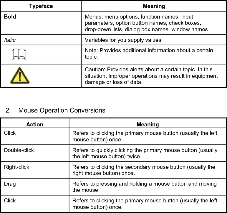
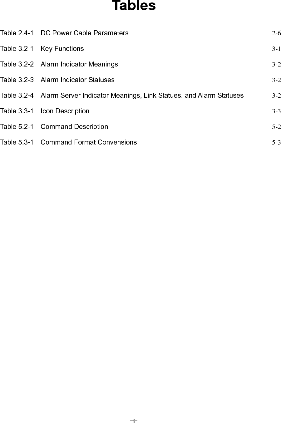
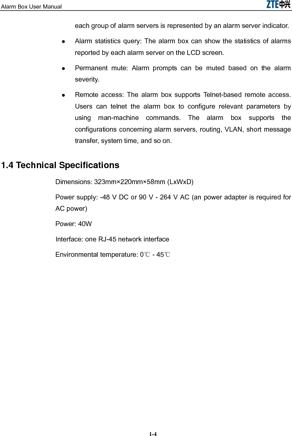


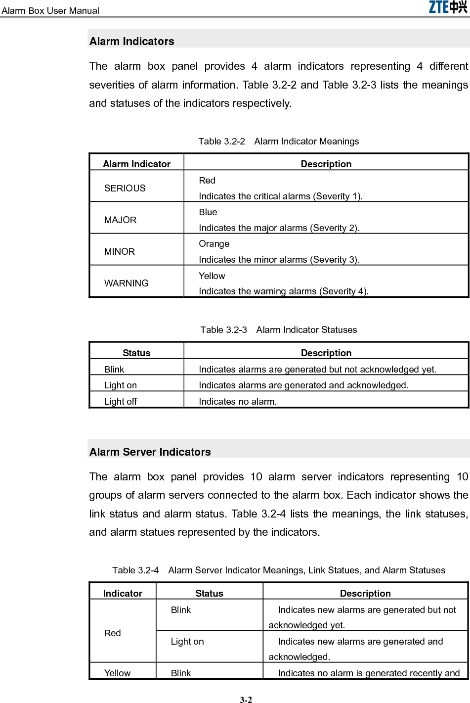
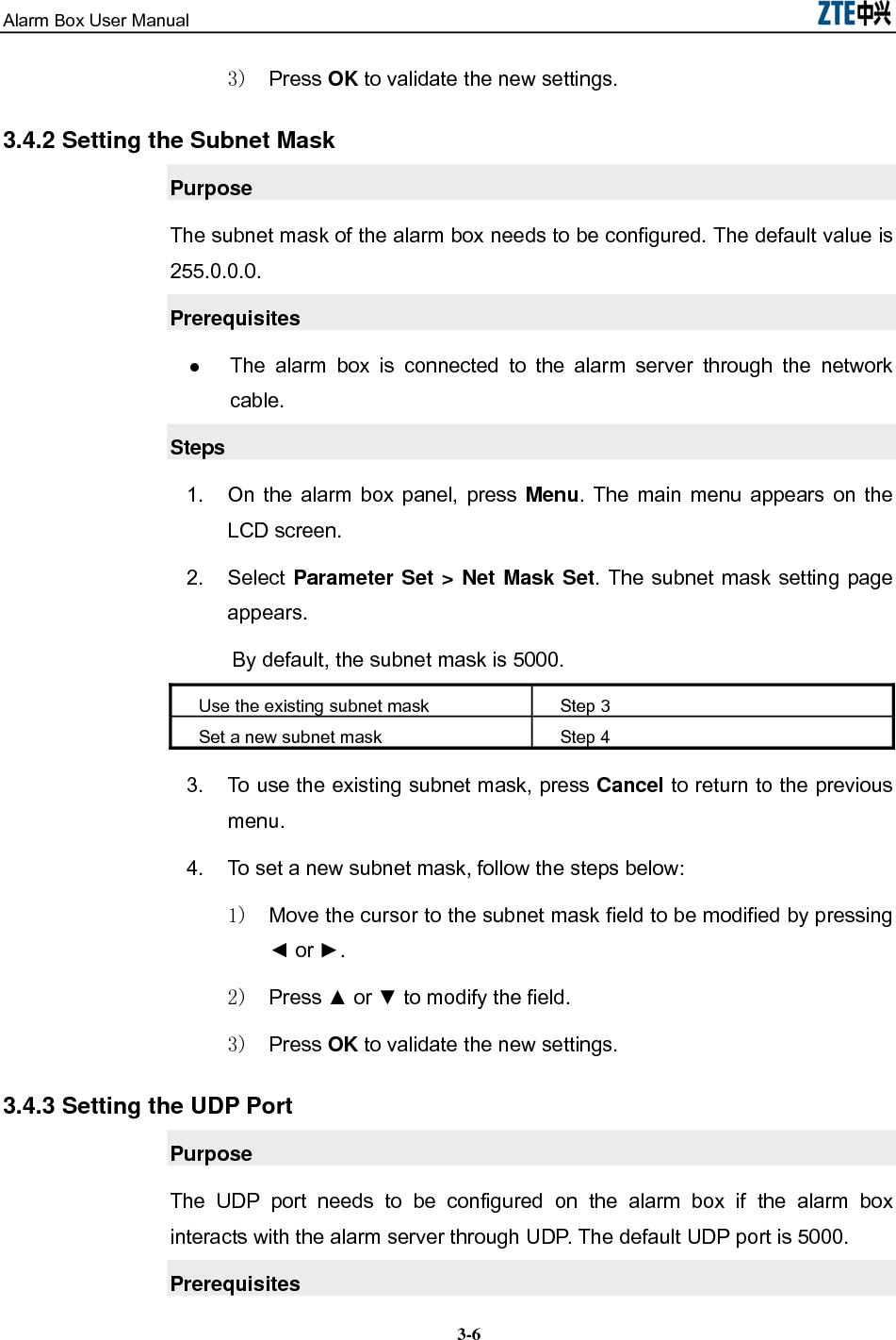
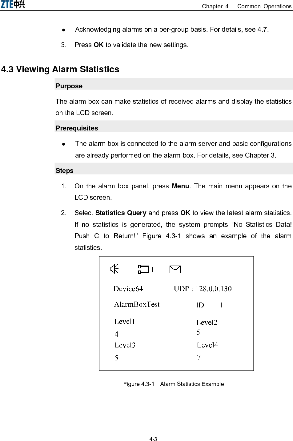
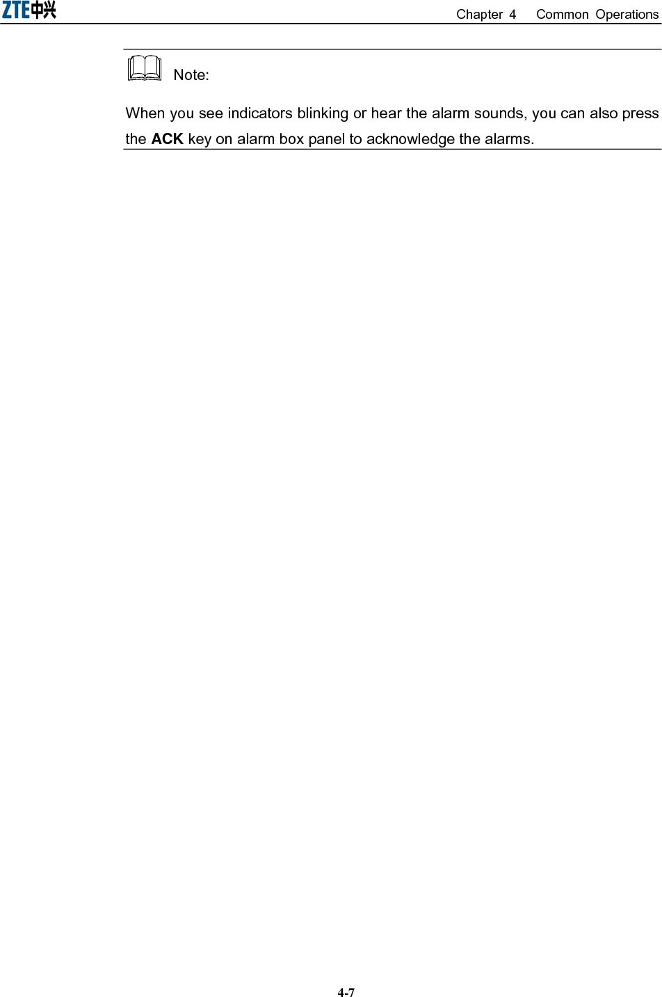
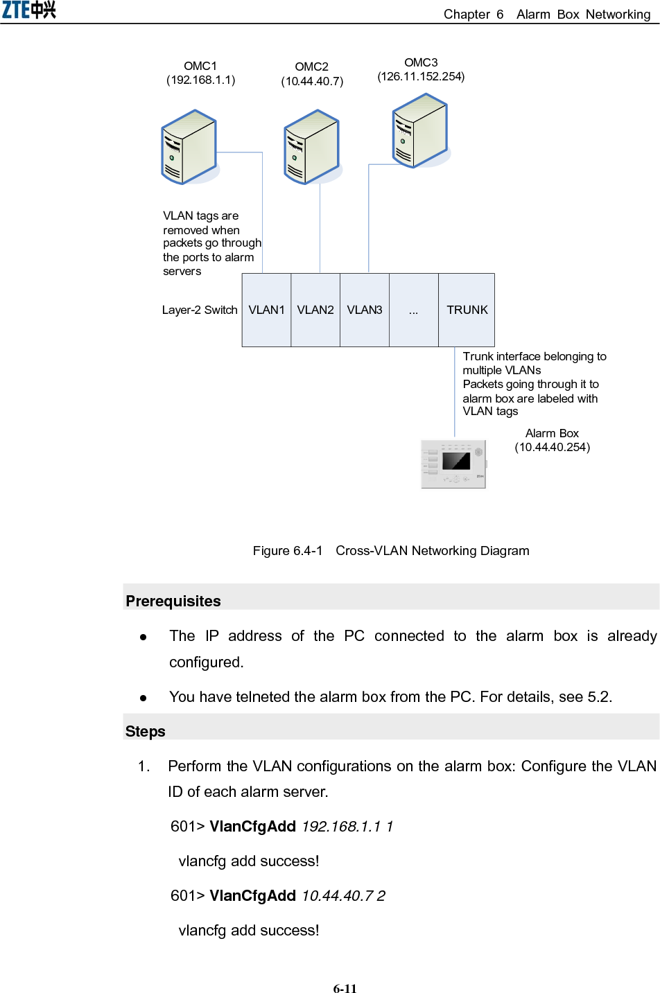
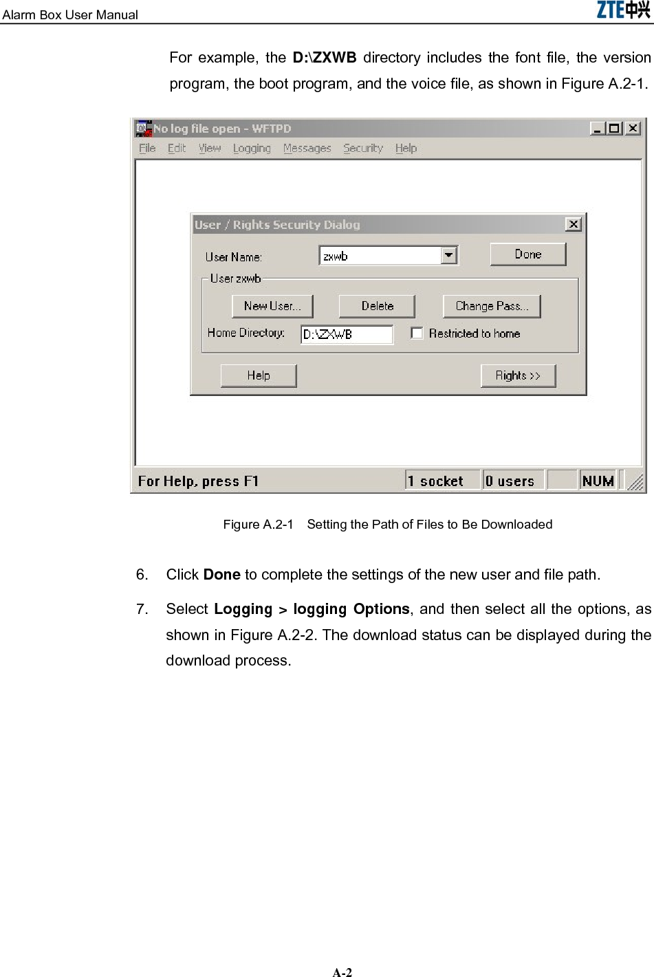
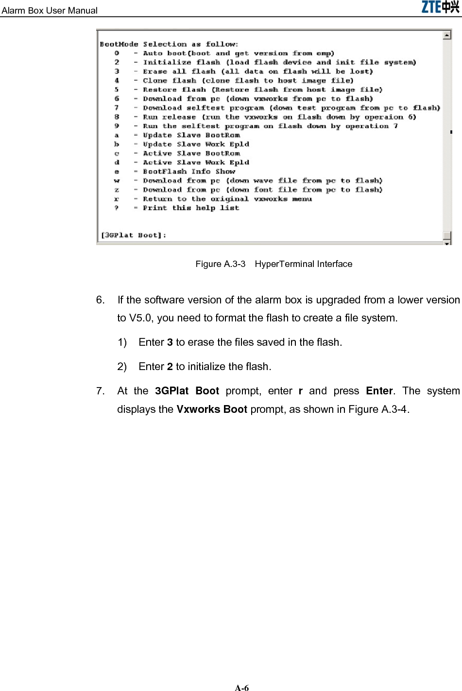
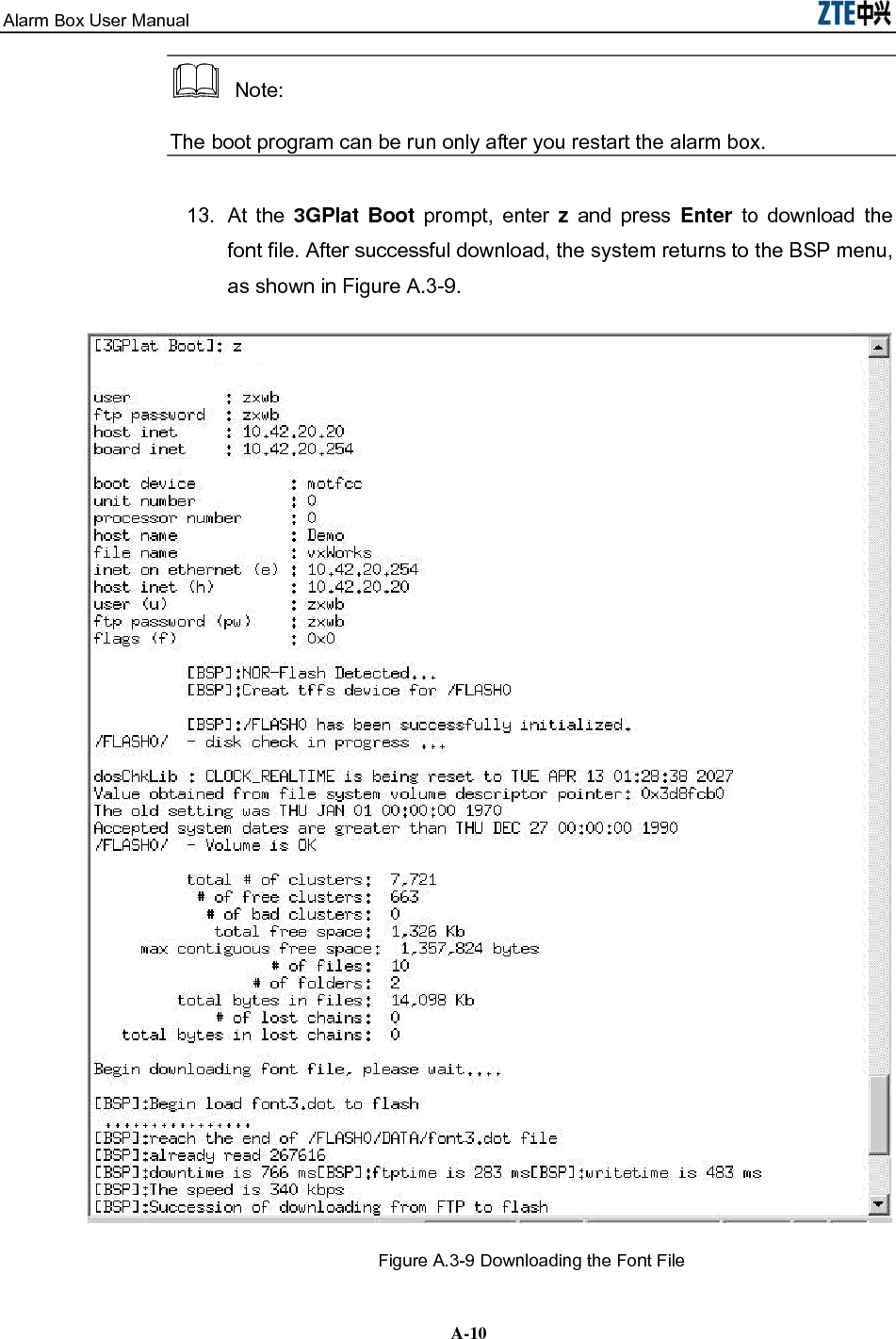
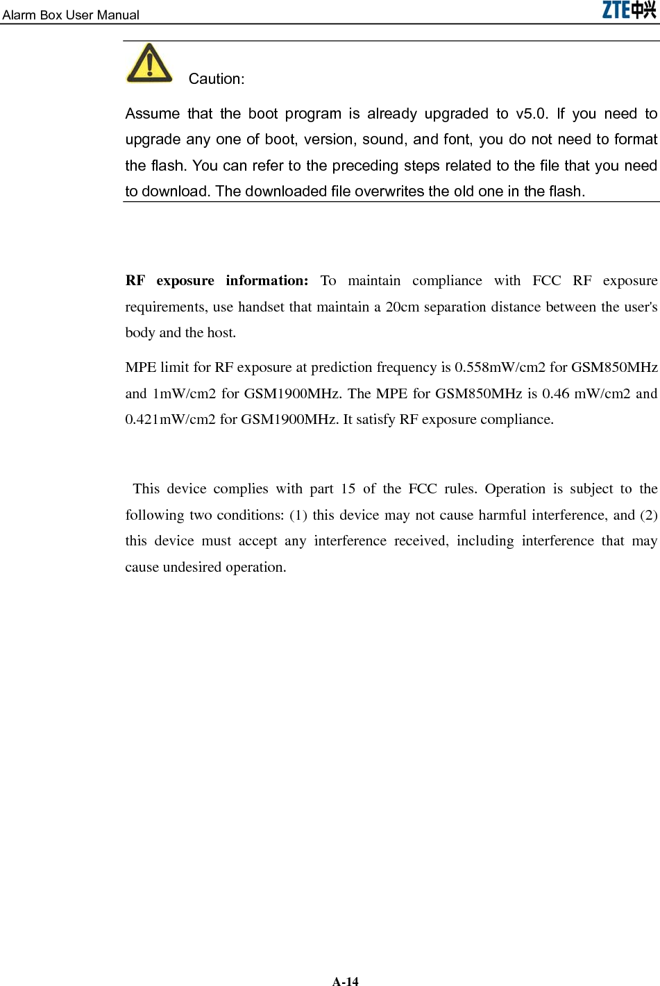
![Alarm Box User Manual 5-24. To view the command list, enter ? and press Enter. Table 5.2-1 lists the commonly used commands. Table 5.2-1 Command Description Command Description Basic Commands ? Lists available commands provided by the alarm box. exit Enables users to log off. ping [Dest] [numpackets] Sends the ping packets. Clock [Year] [Mon] [Day] [Week] [Hour] [Min] [Sec] Sets the current time. tcpCfgShow Displays the TCP connection-related information. cfgTcpComm [Sequence] [Server IP] [Port] [Group ID] Sets up a TCP connection with the alarm server. udpCfgShow Displays the UDP connection-related information. cfgUdpComm [Sequence] [Server IP] [Group ID] Sets up a UDP connection with the alarm server. cfgBureauNo [Bureau No] Sets the bureau number of the alarm box. bureaNoCfgShow [Module No] Displays the bureau number of the alarm box.cfgModuleNo Sets the module number of the alarm box. moduleNoCfgShow Displays the module number of the alarm box.CfgSmsXmit Set the parameters for sending short messages. Routing-Related Commands routeshow Displays the current routing table. routeadd [Dest] [Gateway] Adds routing information to the routing table. routedelete [Dest] [Gateway] Deletes routing information from the routing table. routeFlashShow Displays the routing information saved in the flash. routeSave [Dest] [Gateway] Saves routing information in the flash. routeErase [Sequence] Erases routing information from the flash. VLAN-Related Commands VlanCfgShow Displays all the VLAN configurations of the alarm box. VlanCfgAdd [Server IP] [VLAN ID] Adds VLAN configurations.](https://usermanual.wiki/ZTE/ALARMBOX/User-Guide-1233834-Page-40.png)
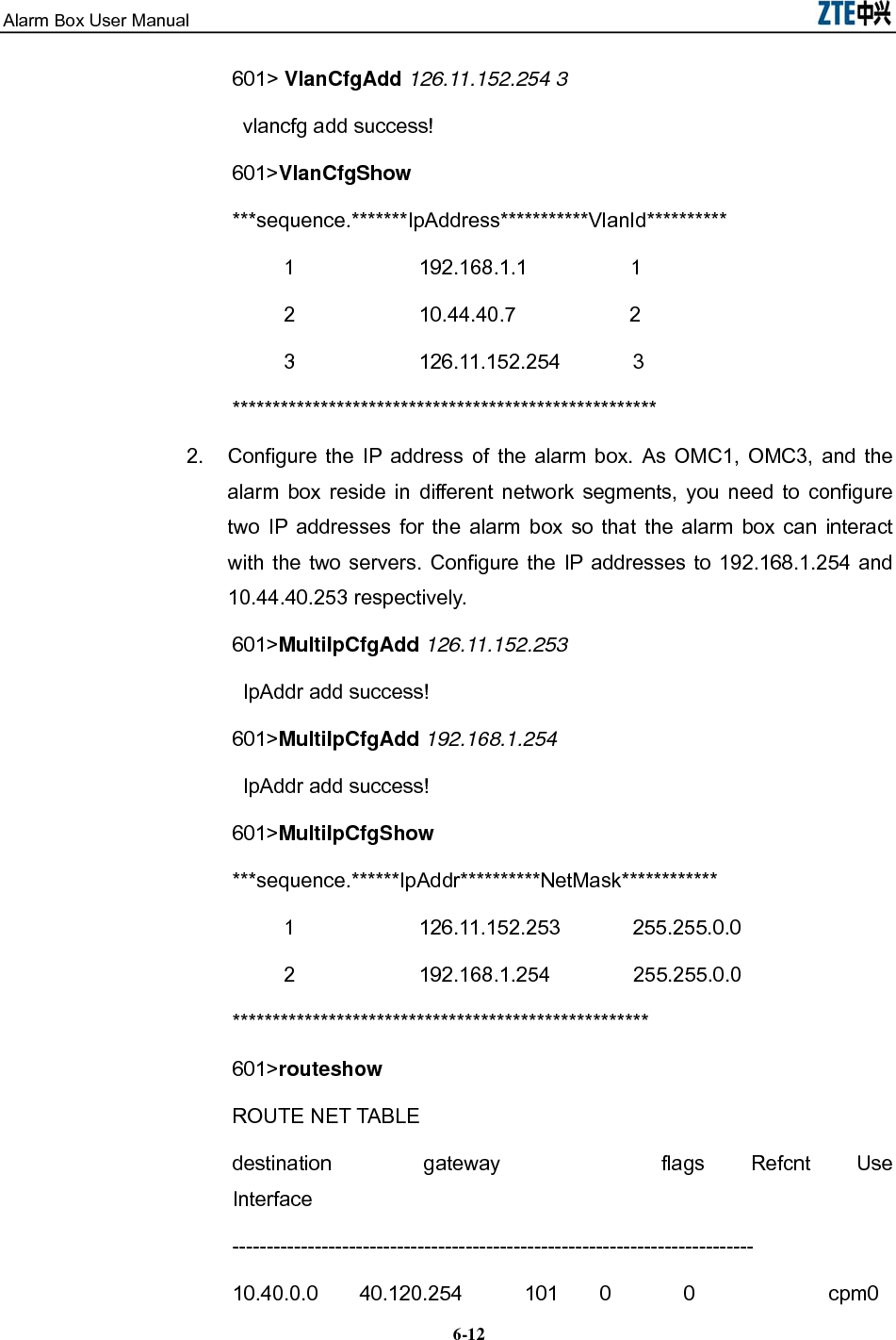
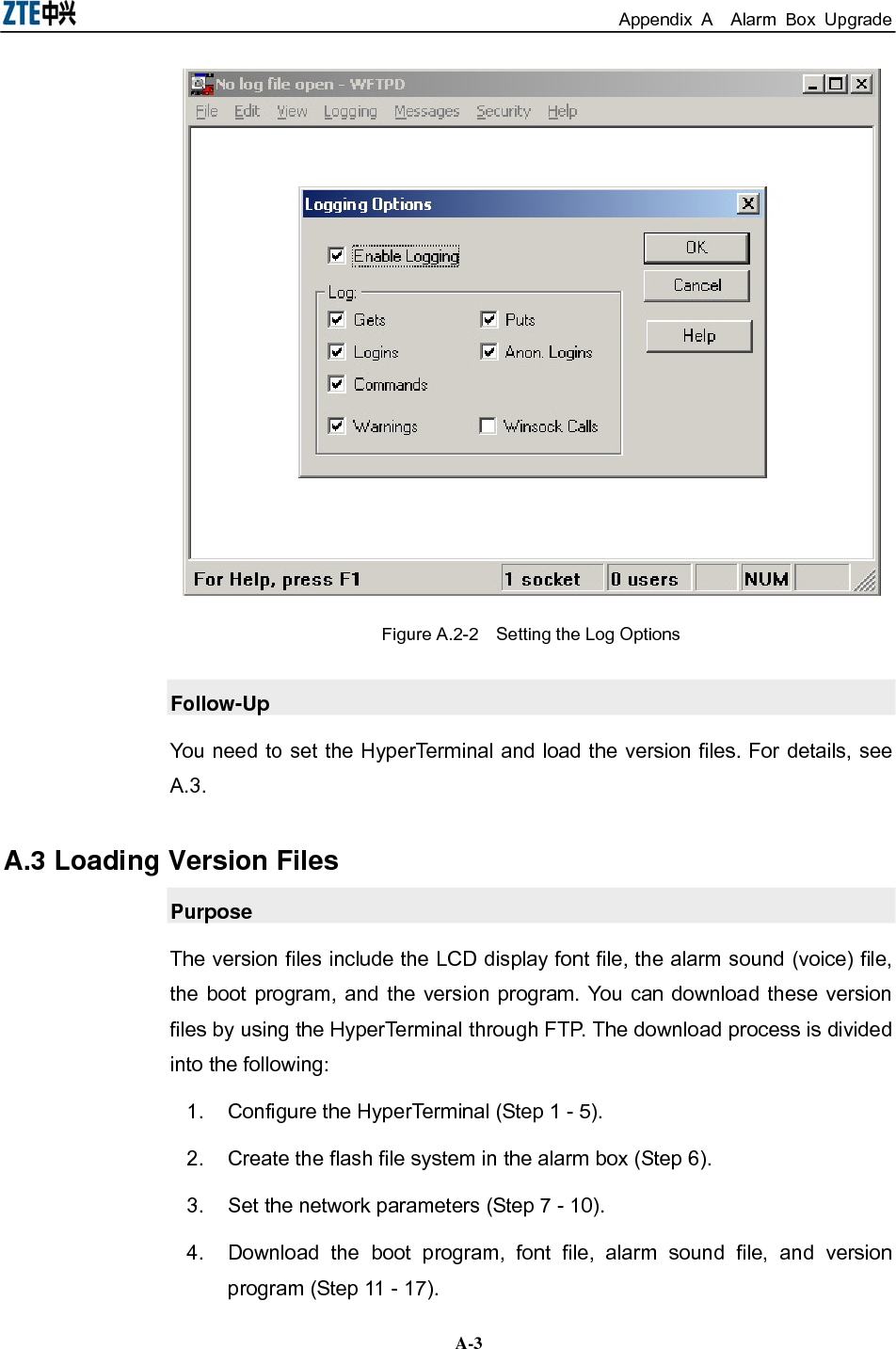
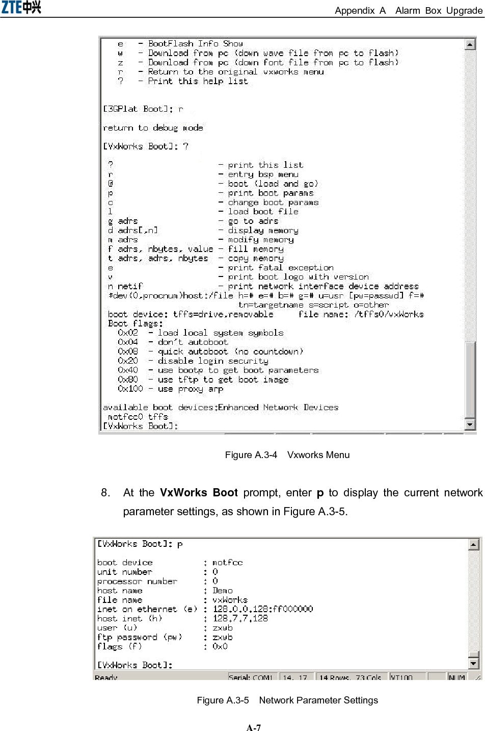
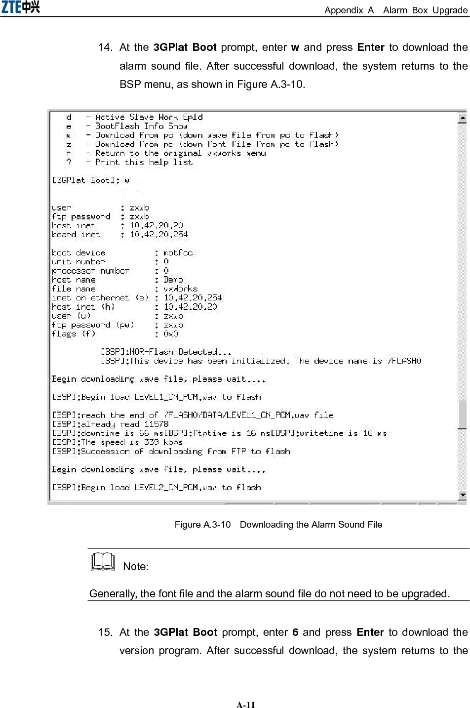
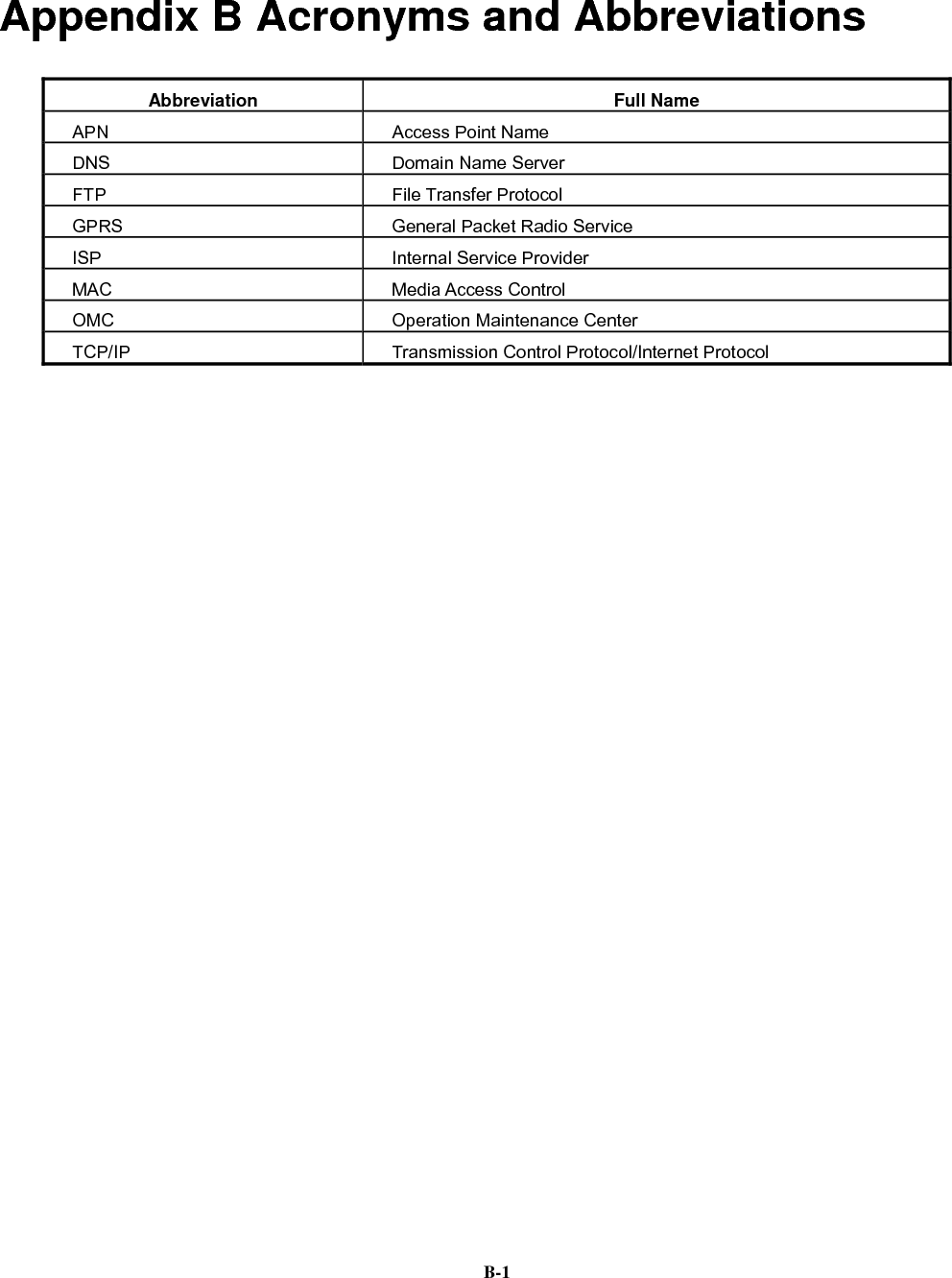
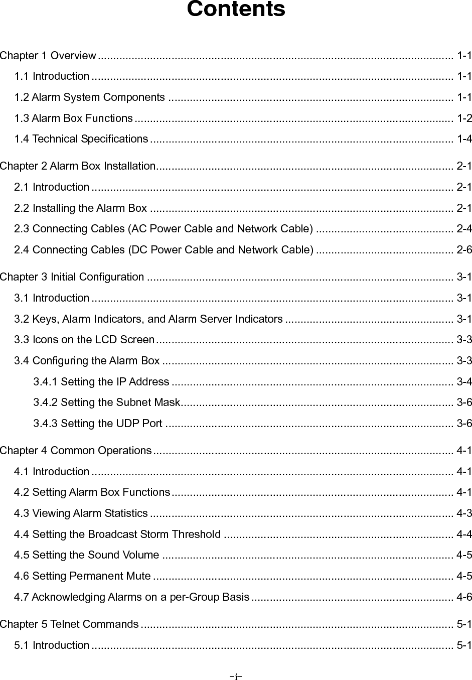
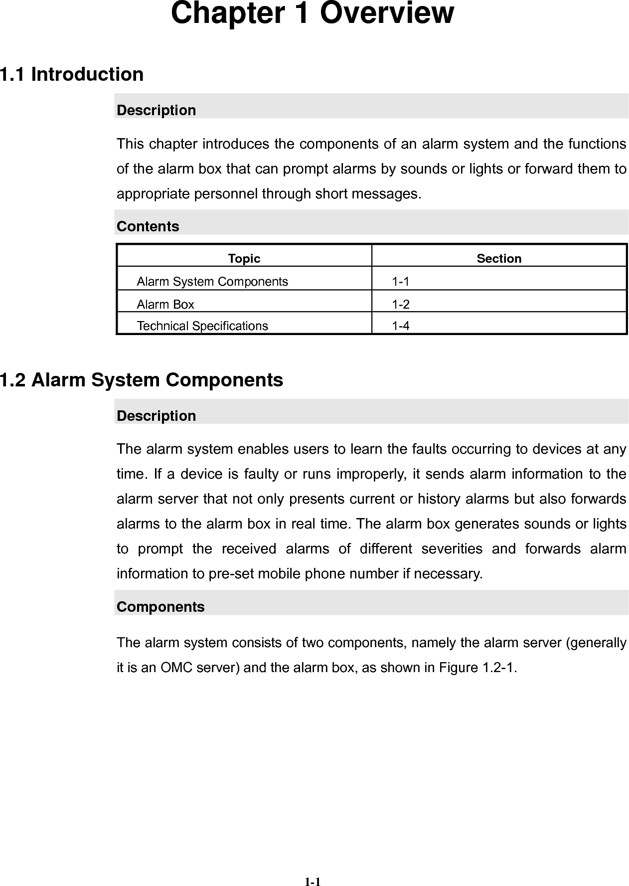
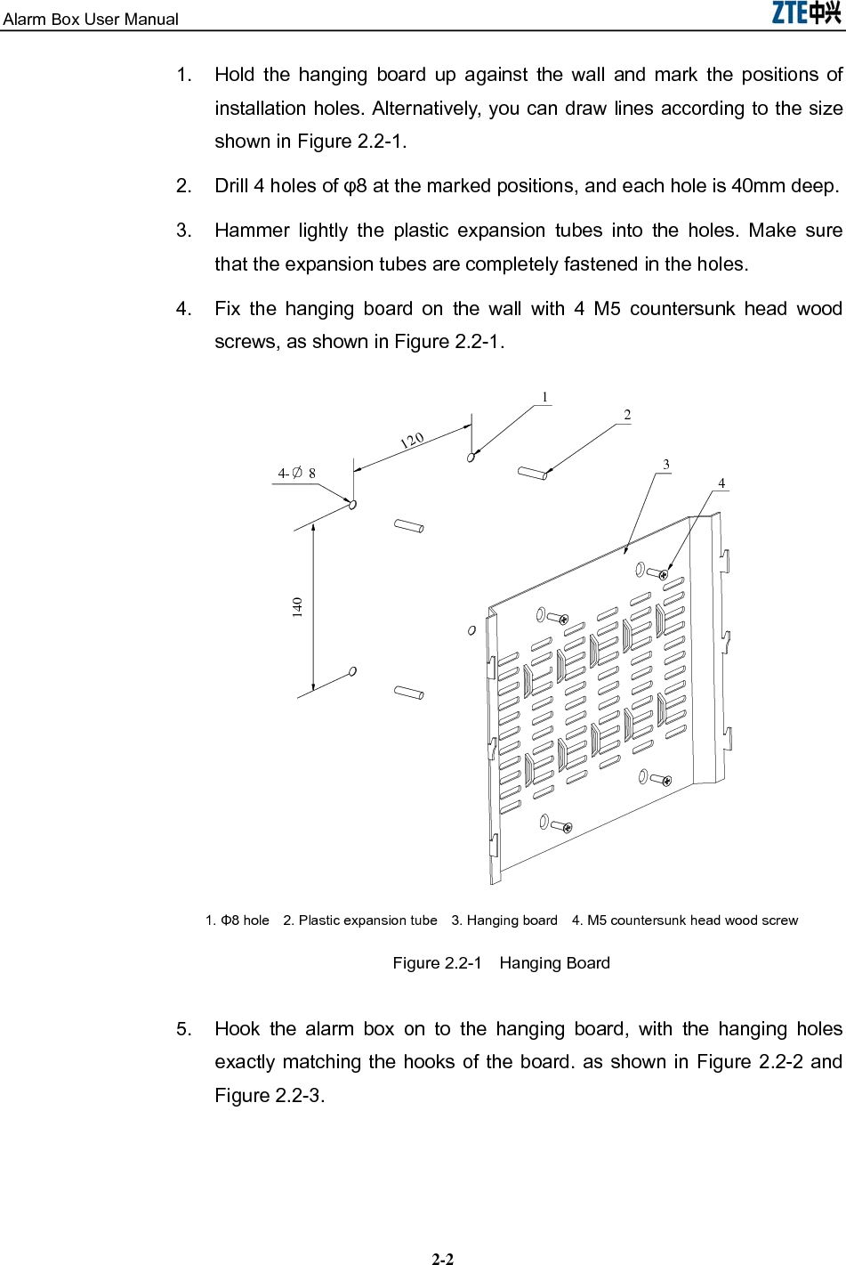
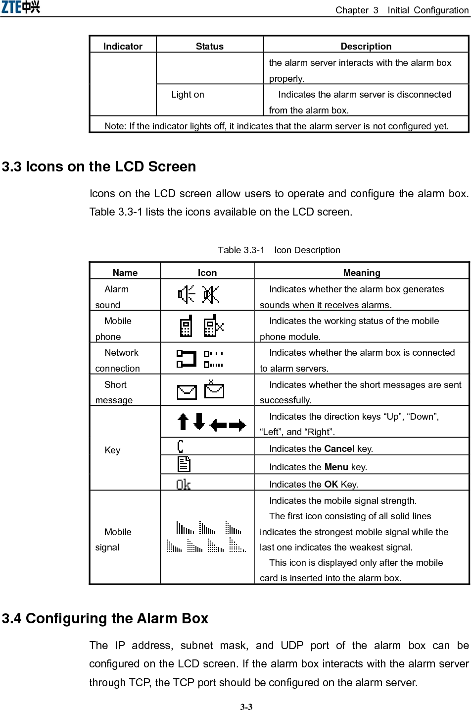
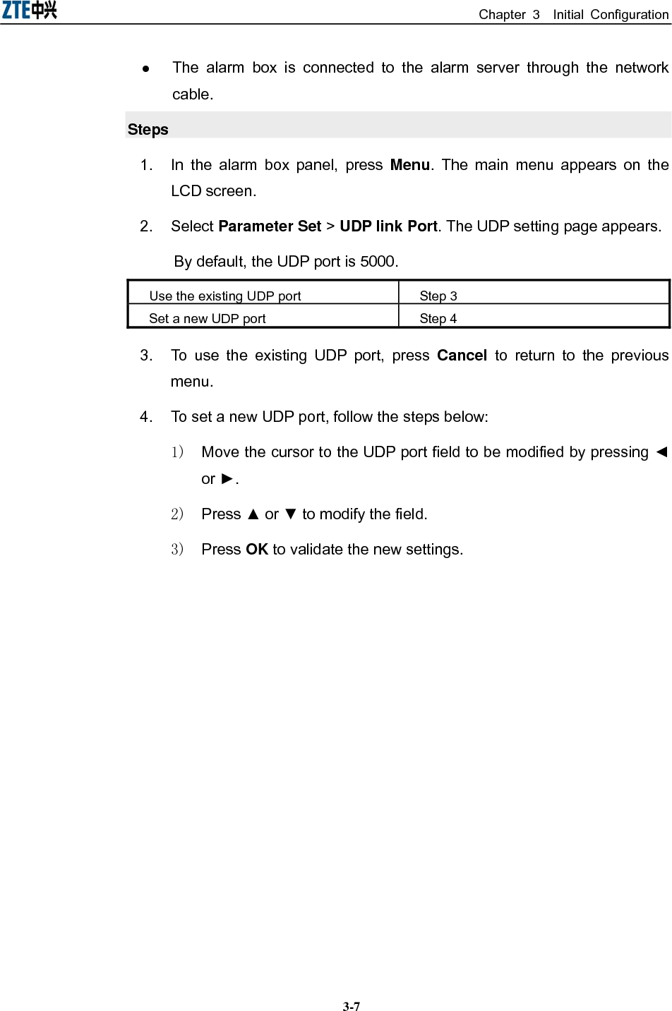
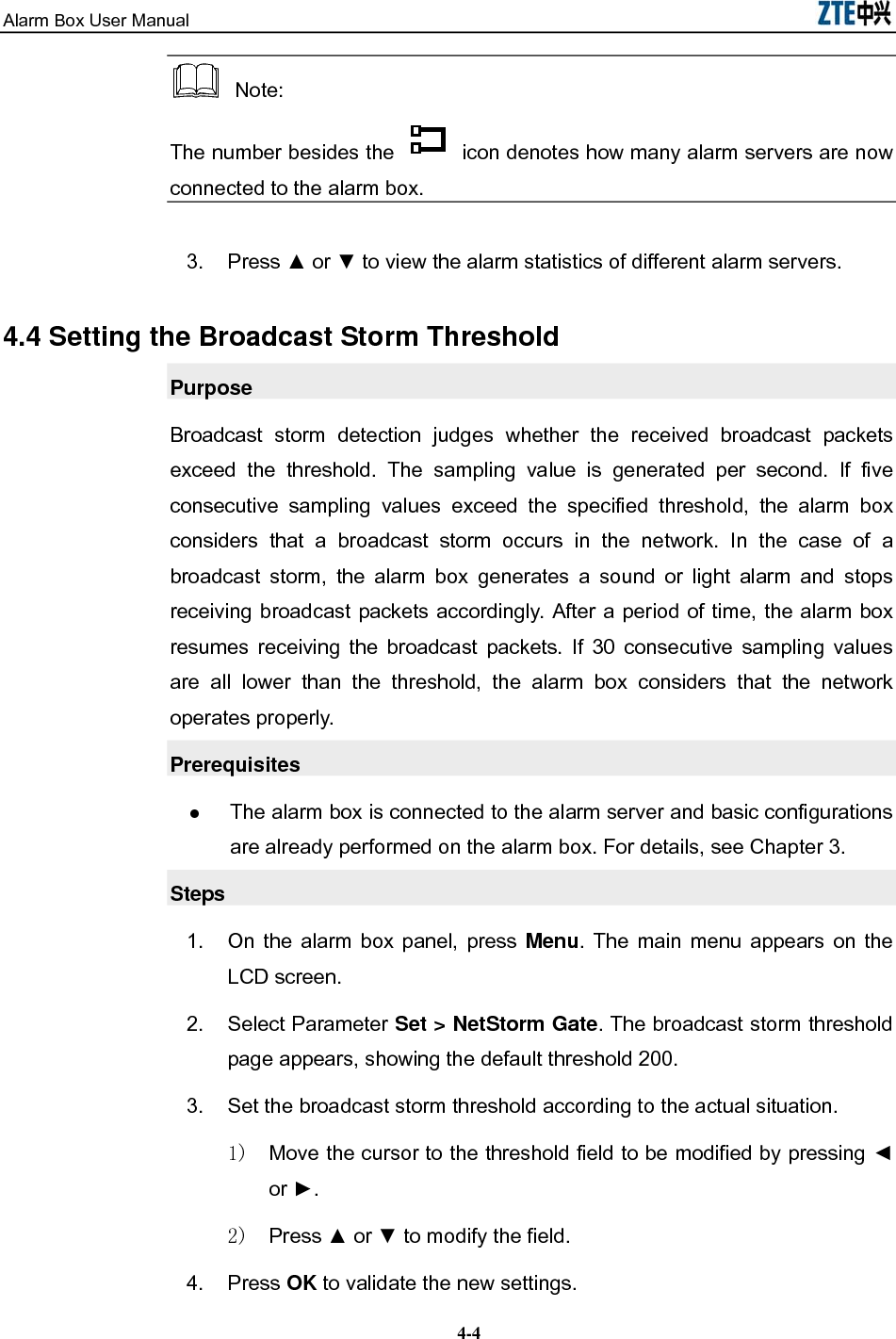
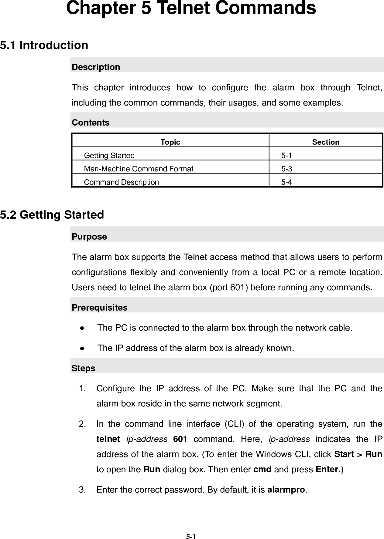
![Chapter 5 Telnet Commands 5-3Command Description VlanCfgDel [Sequence] Deletes VLAN configurations based on the sequence number of the configuration item. VlanCfgBatDel [VLAN ID] Deletes the VLAN configurations in batches based on the VLAN ID. MultiIpCfgShow Displays the IP addresses of the alarm box. MultiIpCfgAdd [IP Address] Adds an IP address to the alarm box. MultiIpCfgDel [Sequence] Deletes IP addresses of the alarm box based on the sequence number. Caution: The commands are case sensitive. 5. Configure the alarm box parameters by referring to the command descriptions. 5.3 Man-Machine Command Format The command format is as follows: Com-mand name Sub-co-mand name Parame-ter name 1 Para-meter 1 Parame-ter name 2 Para-meter 2 Parame-ter name n Para-meter n The items are separated by space. The command help information describes how to use the commands. Table 5.3-1 lists the conventions of the command format. Table 5.3-1 Command Format Conventions Conversions Description /* */ Indicates the note information that does need to be entered. Bold Indicates the commands or keywords. <Italic> Indicates the parameters to be configured. | Separates options and indicates to select one option from two or more options. [ ] Indicates keywords or parameters in it are optional. { } Indicates keywords or parameters in it are mandatory. {x|y|z} Indicates one of x, y, and z should be selected.](https://usermanual.wiki/ZTE/ALARMBOX/User-Guide-1233834-Page-41.png)
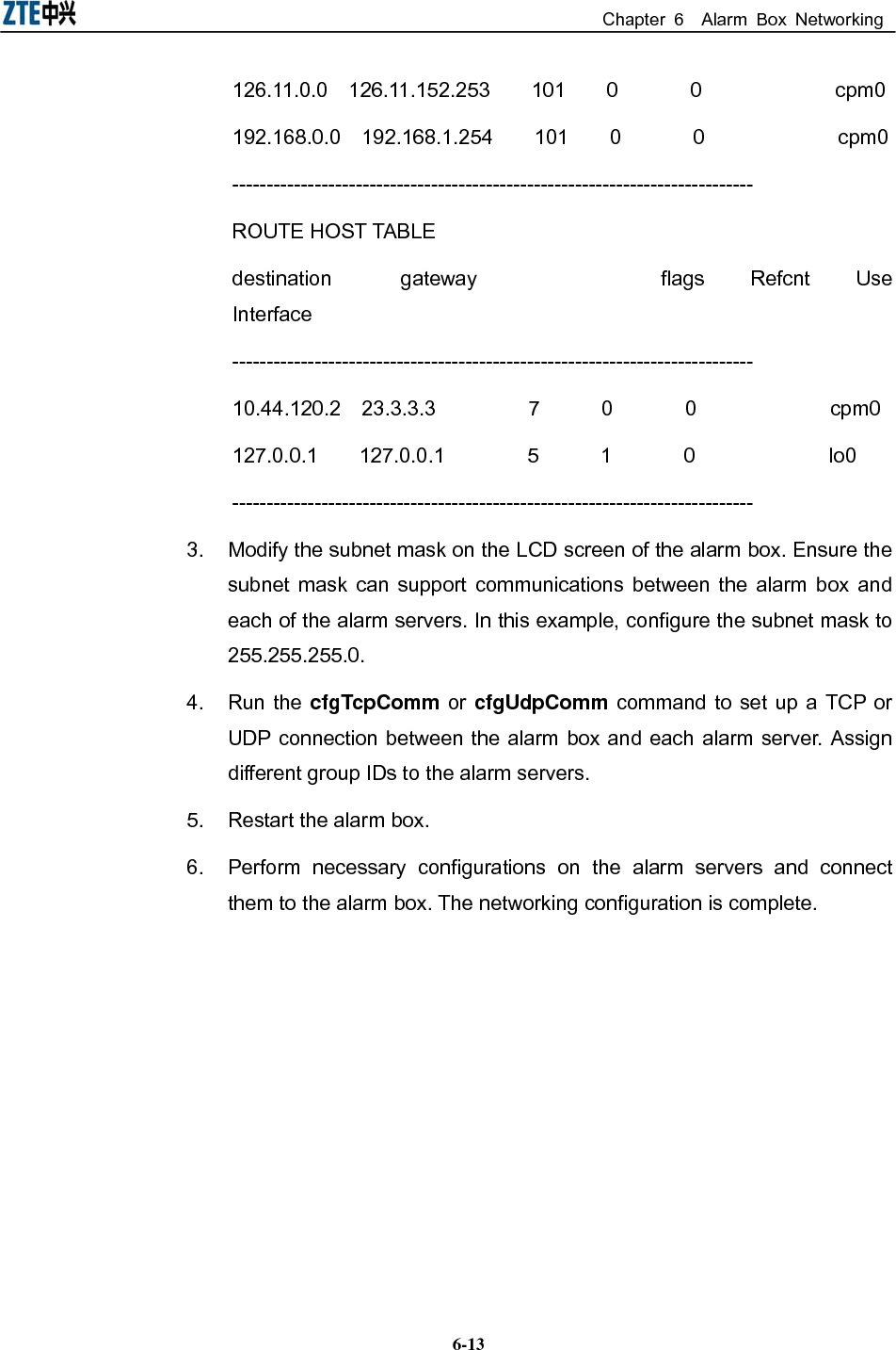
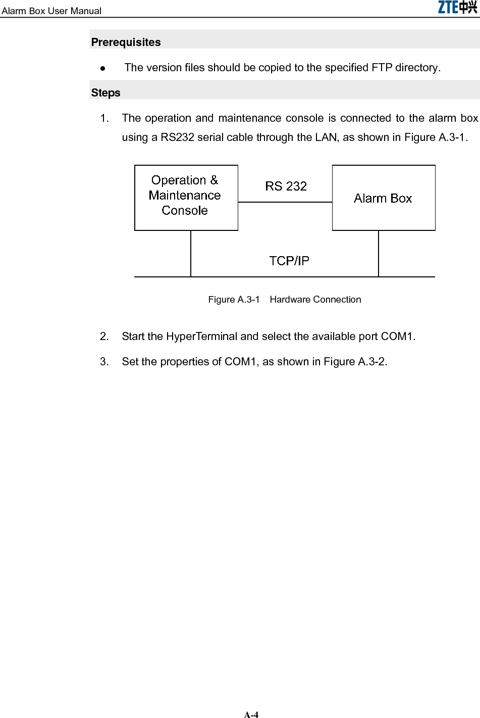
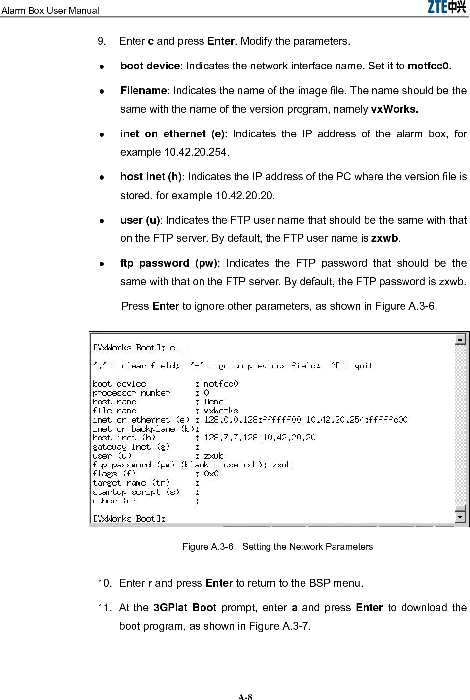
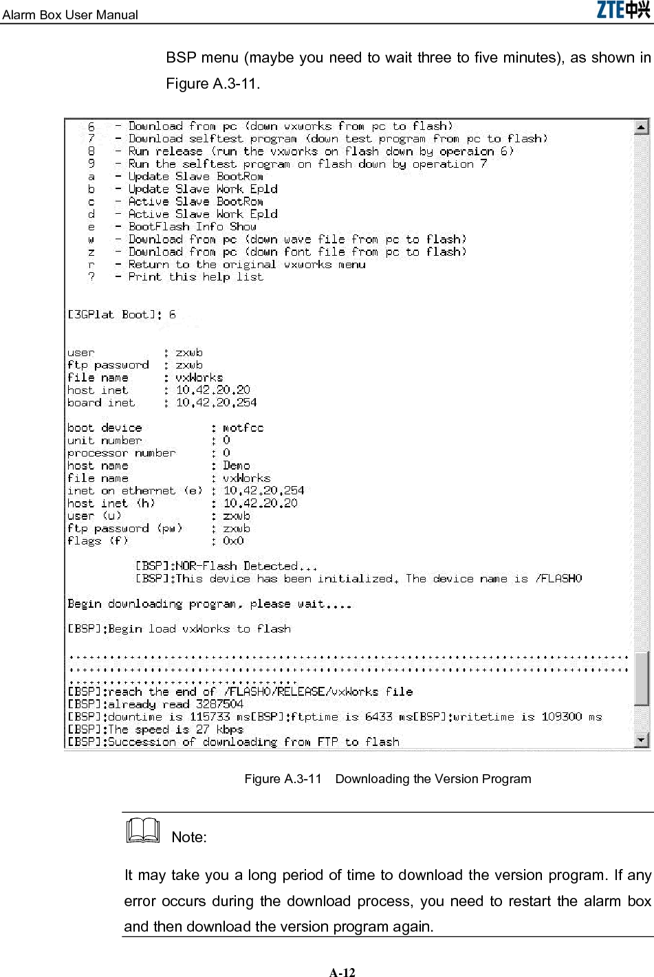
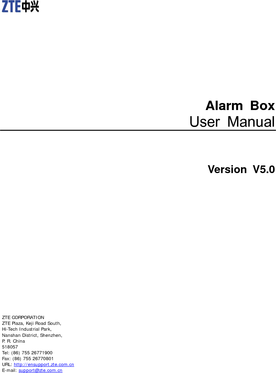
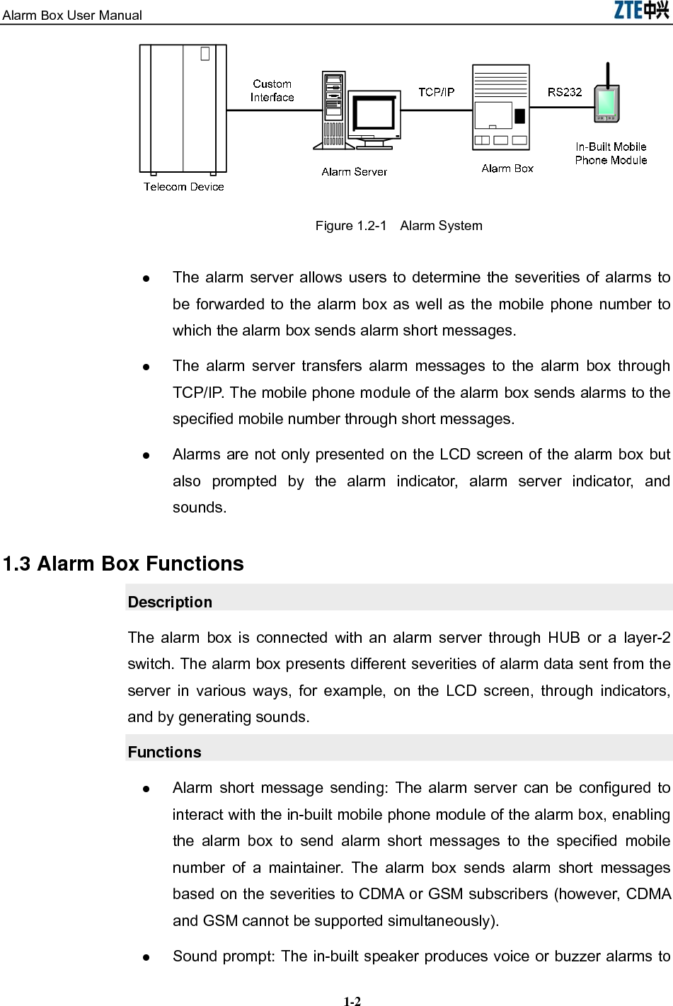
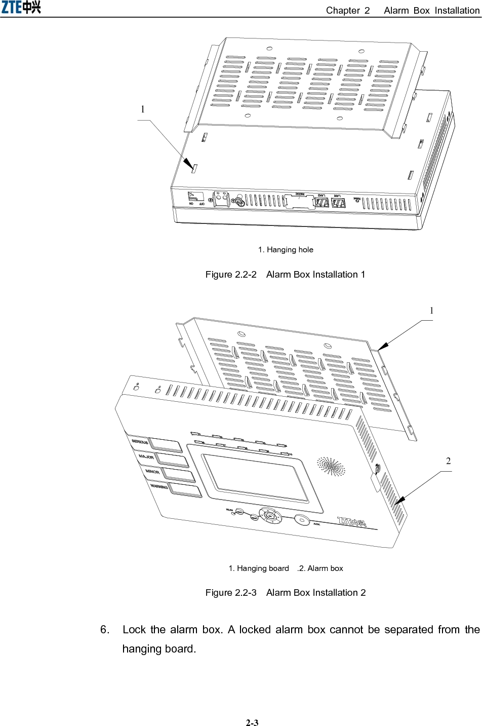
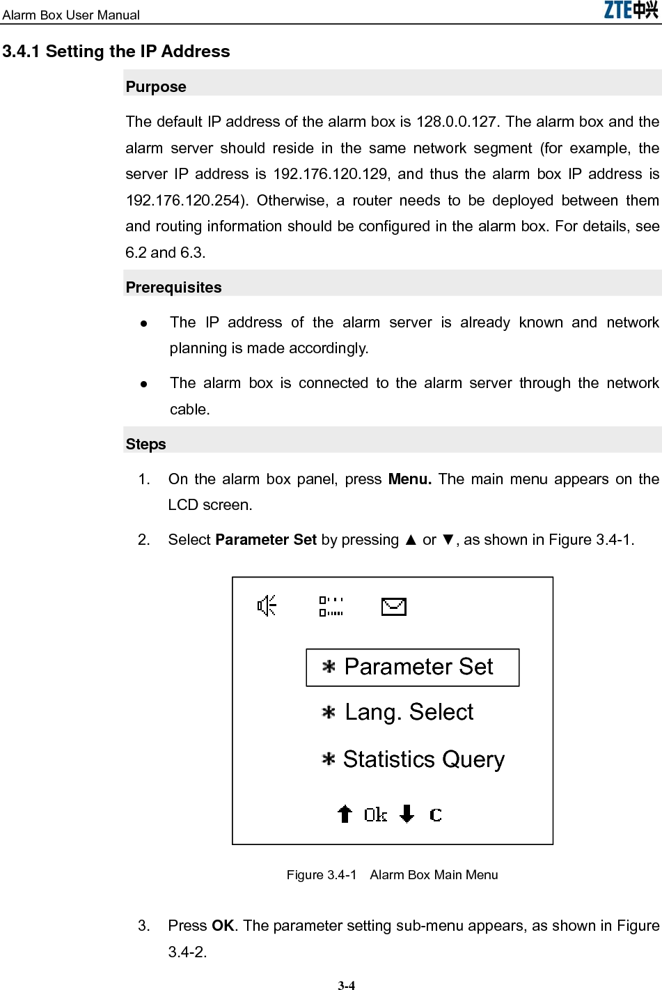
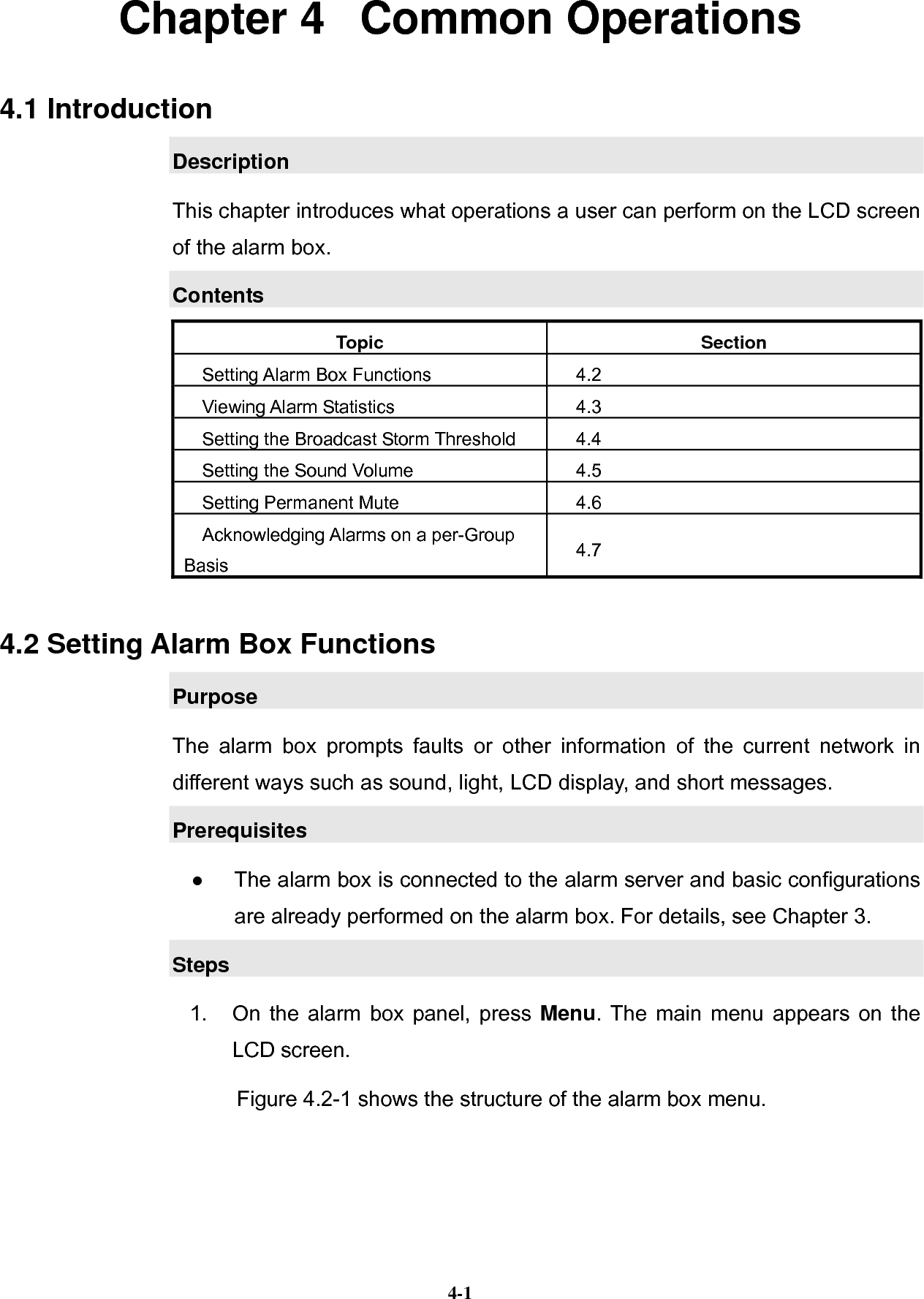
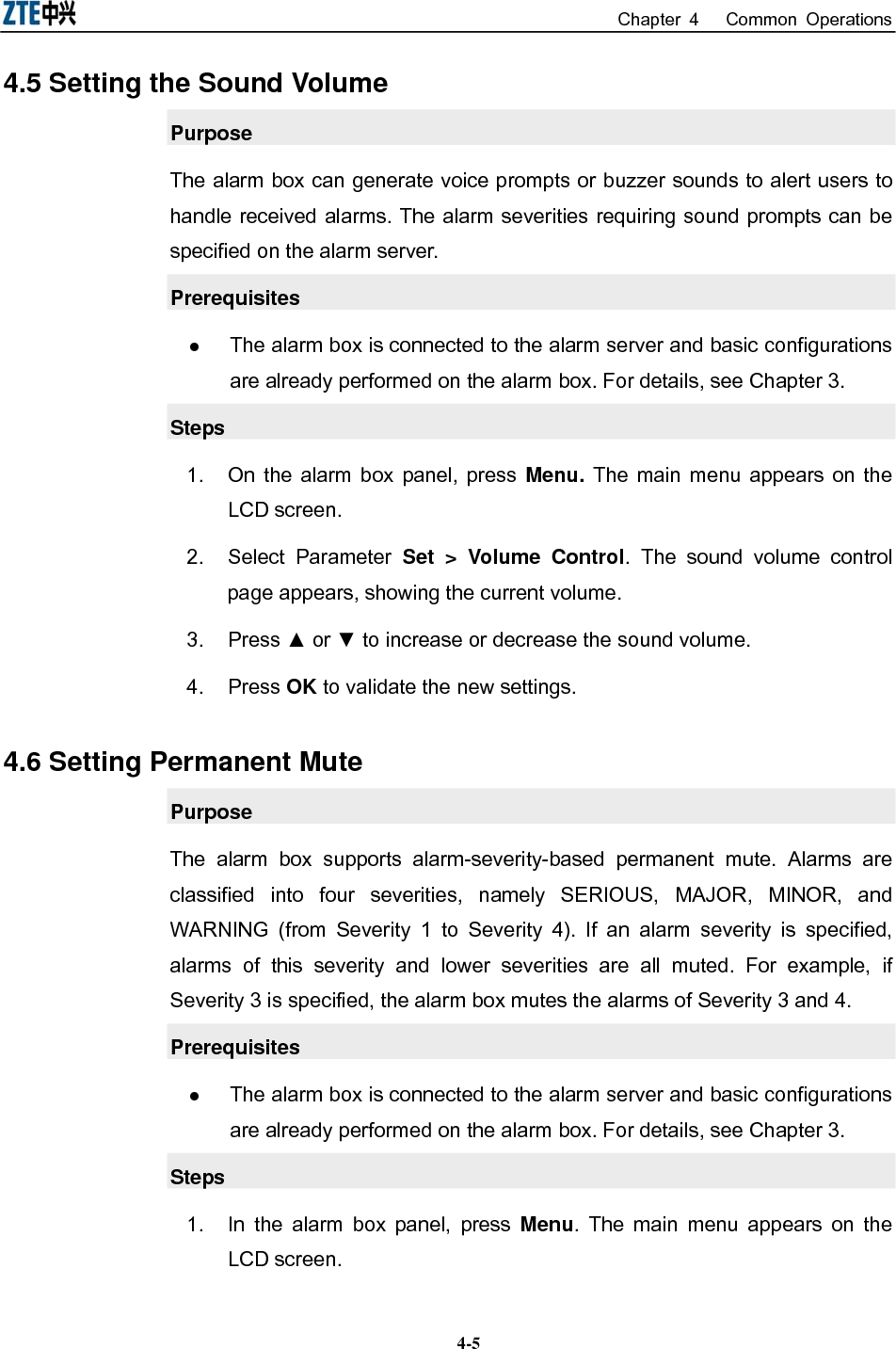
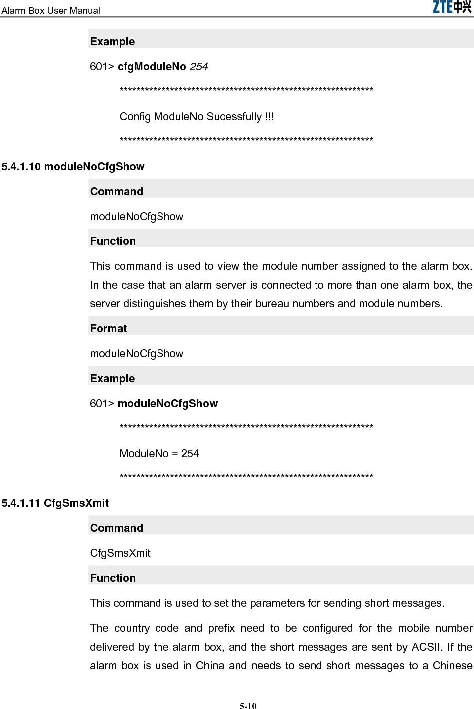
![Alarm Box User Manual 5-4Conversions Description [x{y|z}] Indicates the contents in the square brackets are optional. Moreover, if the contents in the square brackets are selected, either y or z should be used. 5.4 Command Description Description This section introduces the Telnet commands and their usages. These commands are mainly classified into three categories, namely basic commands, routing-related commands, and VLAN-related commands. Contents Topic Section Basic Commands 5-4 Routing-Related Commands 5-13 VLAN-Related Commands 5-17 5.4.1 Basic Commands 5.4.1.1 ping Command ping Function This command is used to check the connectivity and reachability. You can specify the number of the ping packets. Format ping [Dest] [numpackets] Parameter Description Parameter Description Dest Indicates the destination IP address. The ping command checks the connectivity between the local host and the destination. Numpackets Indicates the number of packets to be sent. By default, it is 3.](https://usermanual.wiki/ZTE/ALARMBOX/User-Guide-1233834-Page-42.png)
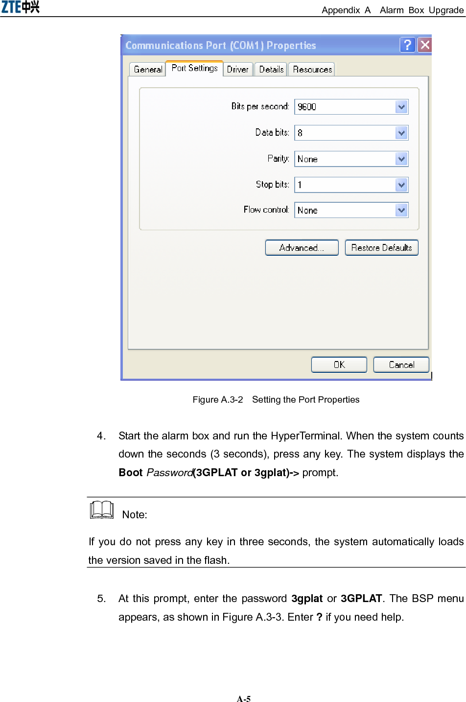
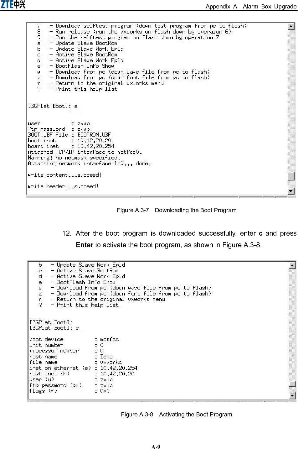
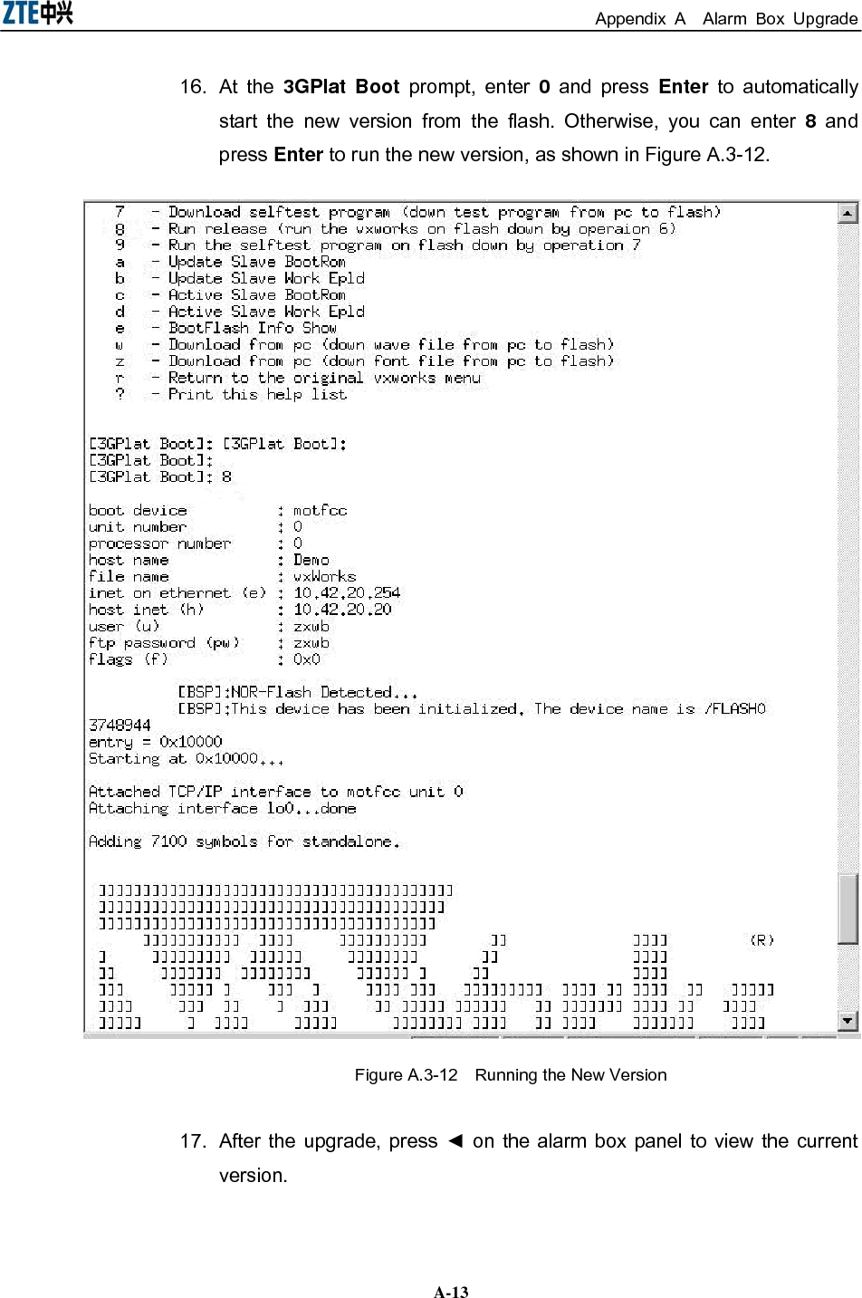
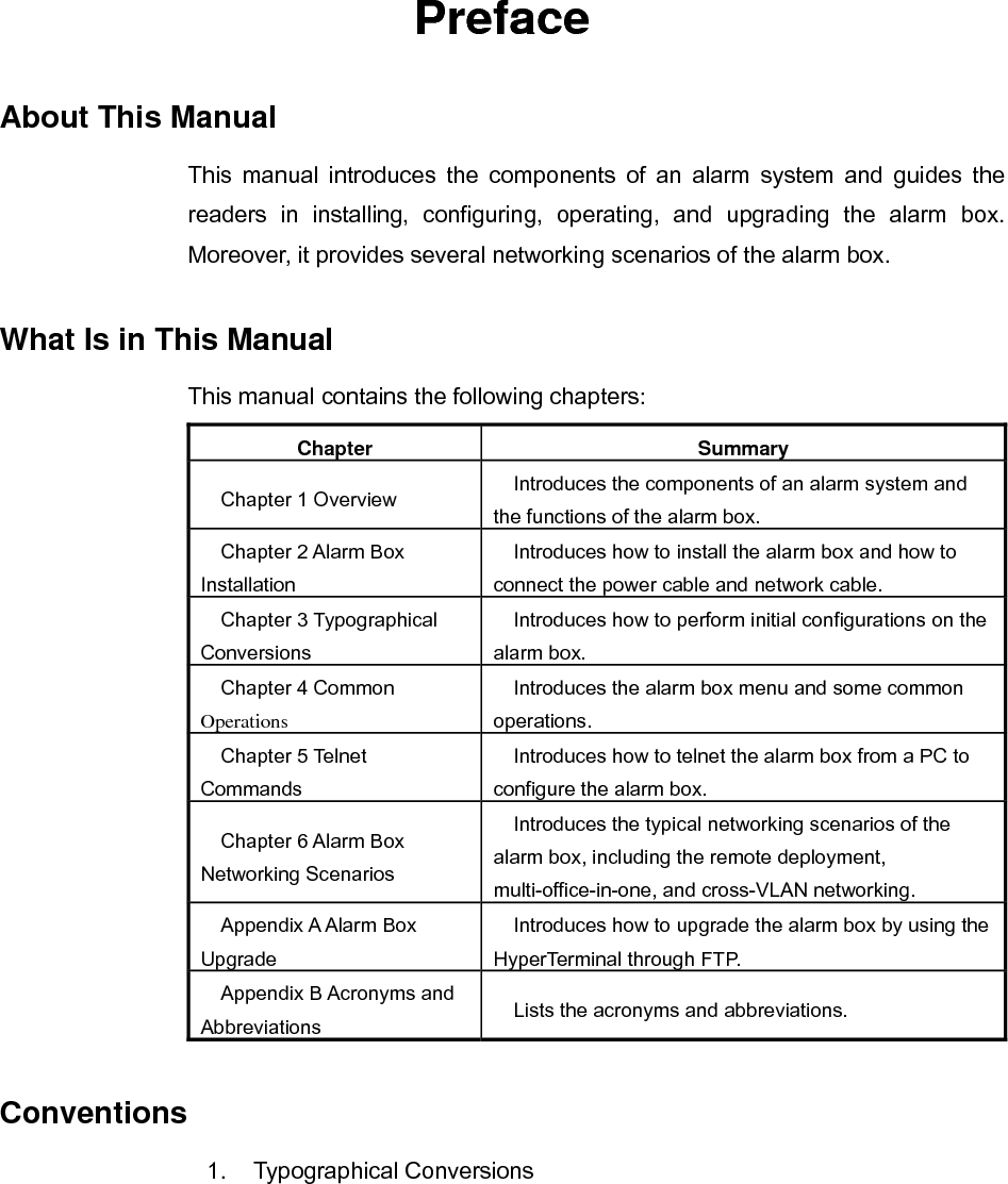
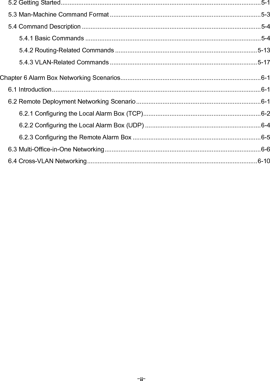
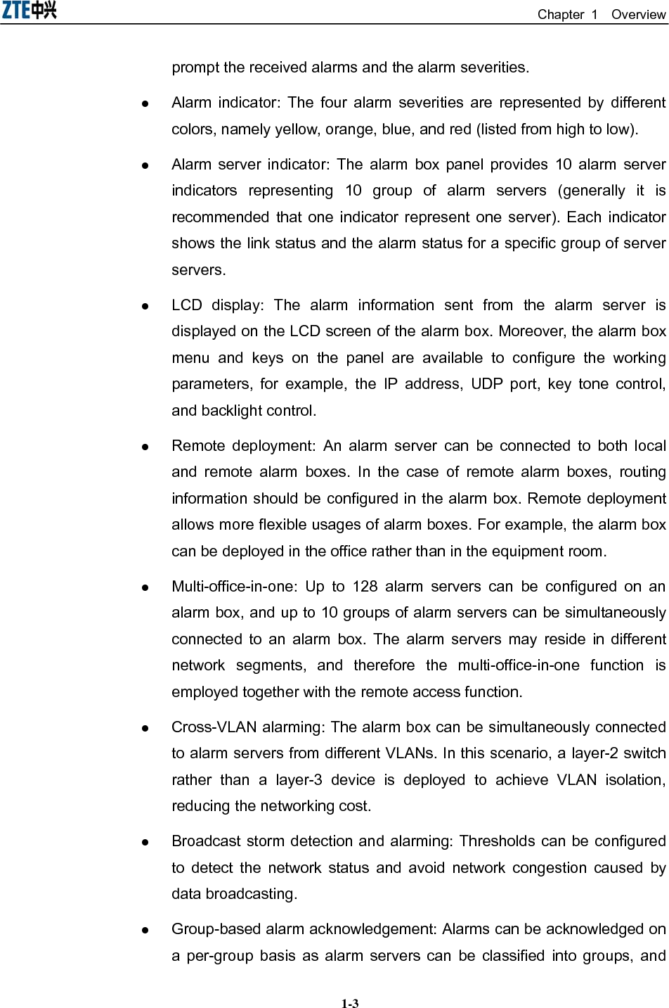
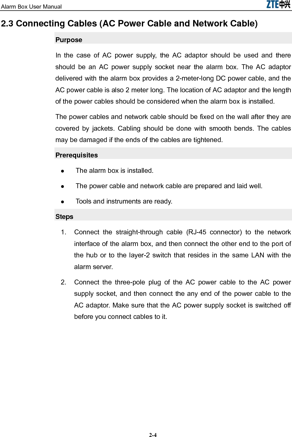
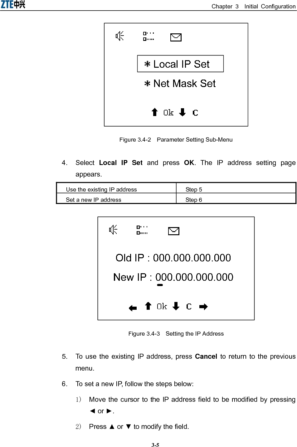
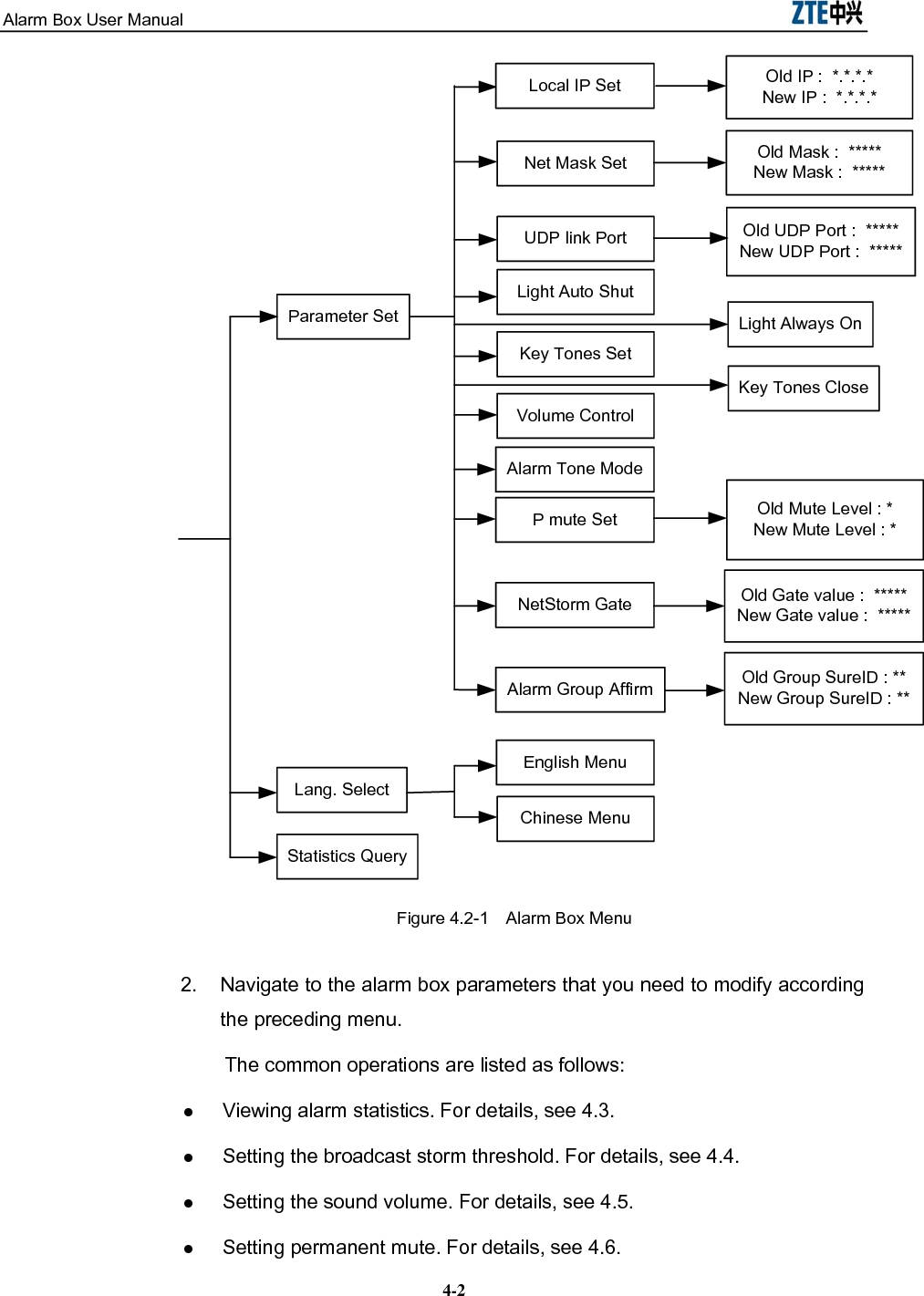
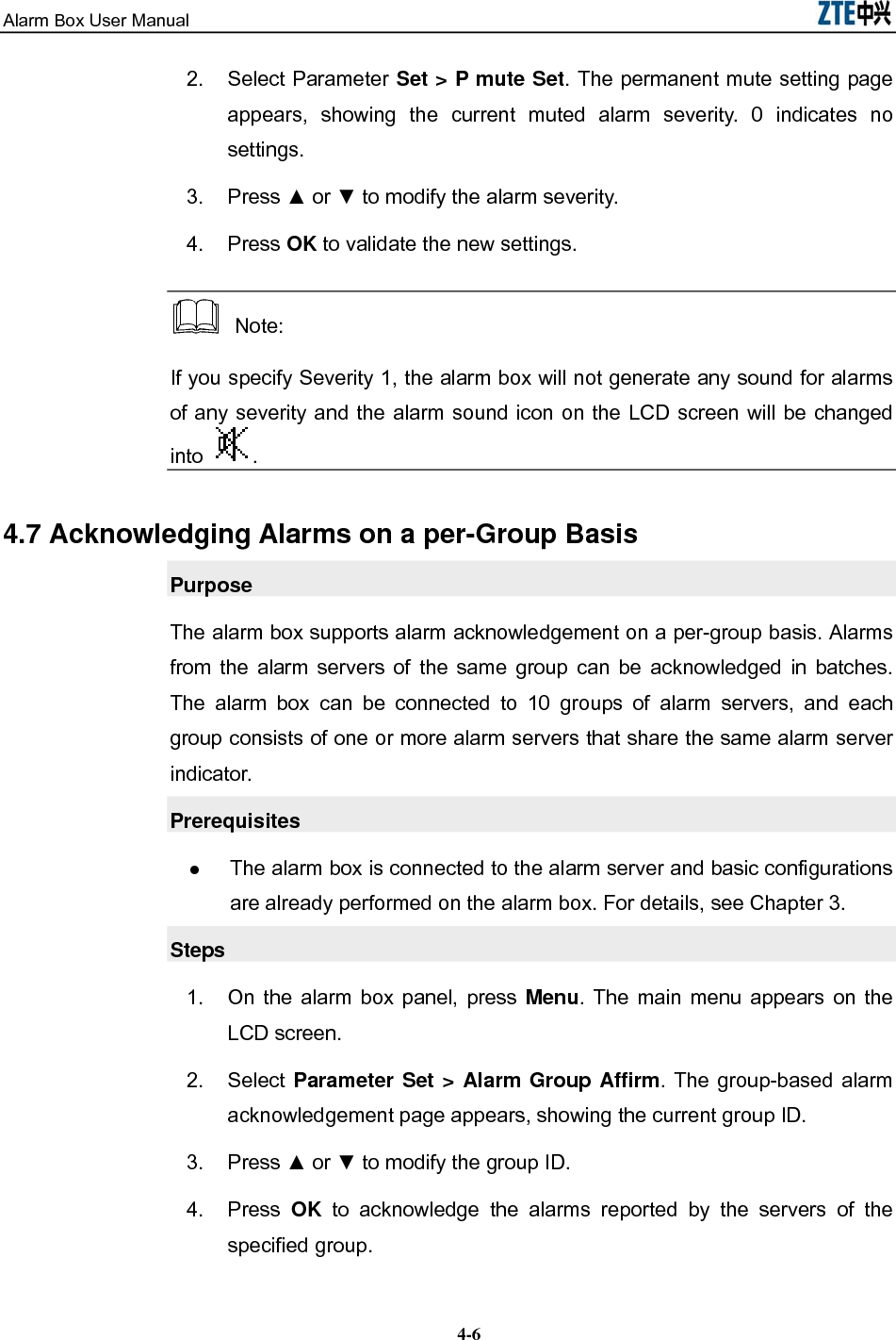
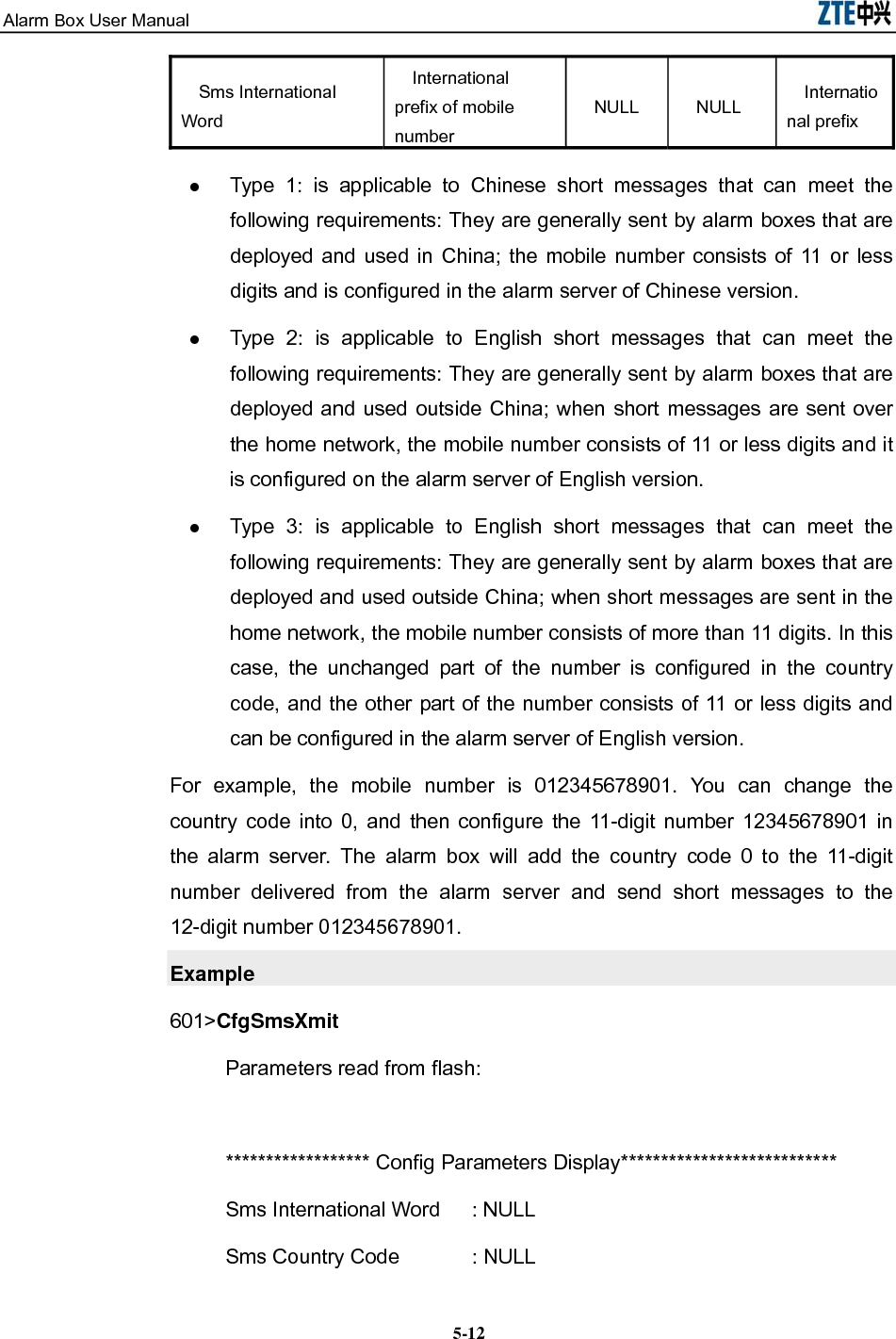
![Chapter 5 Telnet Commands 5-5Example 601>ping 10.41.32.28 5.4.1.2 clock Command clock Function This command is used to set the current system time. Format clock [Year] [Mon] [Day] [Week] [Hour] [Min] [Sec] Example 601>clock 2005 9 7 3 12 20 34 clock is adjust to 2005-9-7 Wed. 12.20.34 5.4.1.3 tcpCfgShow Command tcpCfgShow Function This command is used to view the TCP connection-related information, including the TCP port, the link status, the IP addresses of the alarm box and server, group ID, and so on. Format tcpCfgShow Example 601>tcpCfgShow ************************************************************ LocalIp = 10.42.20.254 (IP address of the alarm box) LocalMask = 255.255.255.0 (Subnet mask of the alarm box) ***********Sequence 0 :****************](https://usermanual.wiki/ZTE/ALARMBOX/User-Guide-1233834-Page-43.png)
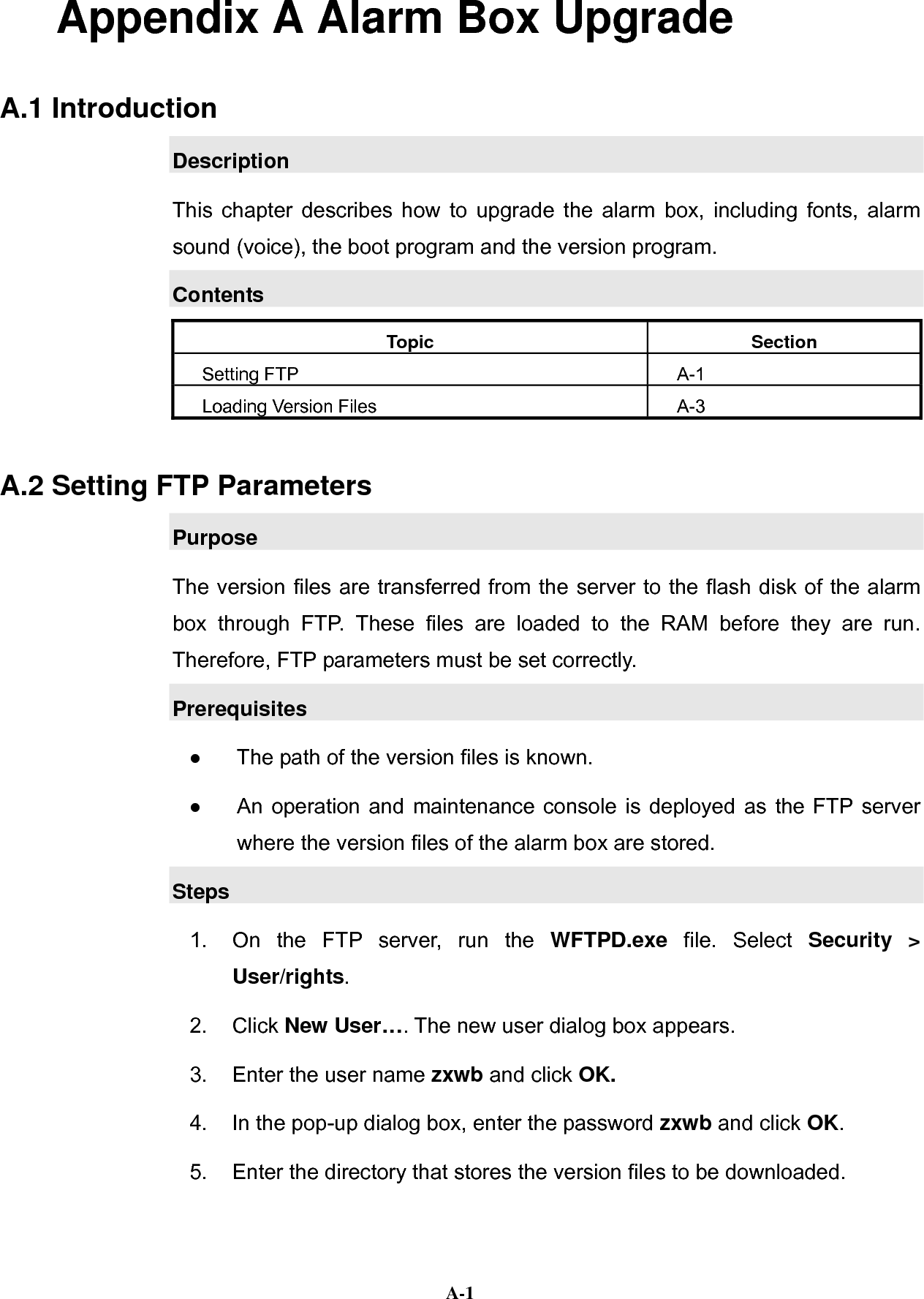
![Alarm Box User Manual 5-6Port0 = 5000 (TCP Port) ServerIp0 = 195.152.115.129 (IP address of the alarm server) Groupid0=1 (Group that the server belongs to) Link0State:Active (Link status) ************************************************************ 5.4.1.4 cfgTcpComm Command cfgTcpComm Function The alarm box can be simultaneously connected to 10 groups of alarm servers. If the alarm box interacts with an alarm server through TCP, you need to set up a TCP connection between the alarm box and the server by using the cfgTcpComm command. Format cfgTcpComm [Sequence] [Server IP] [Port] [Group ID] Parameter Description Parameter Description Sequence Indicates the sequence number of the alarm number. The value ranges from 0 to 63. Server IP Indicates the IP address of the alarm server. Port Indicates the TCP port configured on the alarm server. Group ID Indicates the ID of the group that the alarm server belongs to. The value ranges from 1 to 10. Example 601> cfgTcpComm 1 195.152.115.129 5000 1 ************************************************************ TcpServer1 Set succeed !!! ************************************************************](https://usermanual.wiki/ZTE/ALARMBOX/User-Guide-1233834-Page-44.png)
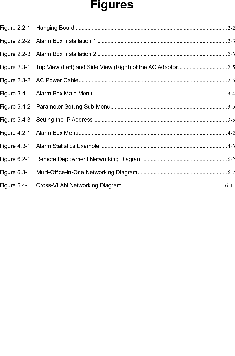
![Chapter 5 Telnet Commands 5-75.4.1.5 udpCfgShow Command udpCfgShow Function This command is used to view the UDP connection-related information, including the UDP port, the link status, the IP address of the alarm server, group ID, and so on. Format udpCfgShow Example 601>udpCfgShow ************************************************************ ***********Sequence 64 :**************** Port = 5000 (UDP port) ServerIp64 = 195.152.115.129 (IP address of the alarm server) Groupid64=0 (Group that the server belongs to) Link64State:Active (Link status) ************************************************************ 5.4.1.6 cfgUdpComm Command cfgUdpComm Function The alarm box can be simultaneously connected to 10 groups of alarm servers. If the alarm box interacts with an alarm server through UDP, you need to set up a UDP connection between the alarm box and the server by using the cfgUdpComm command. Format udpTcpComm [Sequence] [Server IP] [Group ID]](https://usermanual.wiki/ZTE/ALARMBOX/User-Guide-1233834-Page-45.png)
![Alarm Box User Manual 5-8Parameter Description Parameter Description Sequence Indicates the sequence number of the alarm number. The value ranges from 64 to 127. Server IP Indicates the IP address of the alarm server. Group ID Indicates the ID of the group that the alarm server belongs to. The value ranges from 1 to 10. Example 601>cfgUdpComm 64 195.152.115.128 1 ************************************************************ UdpServer1 Set succeed !!! ************************************************************ 5.4.1.7 cfgBureauNo Command cfgBureauNo Function This command is used to assign a bureau number to the alarm box. In the case that an alarm server is connected to more than one alarm box, the server distinguishes them by their bureau numbers and module numbers. Format cfgBureauNo [Bureau No] Parameter Description Parameter Description Bureau No Indicates the bureau number assigned to the alarm box. Example 601> cfgBureauNo 1 ************************************************************ Config BureauNo Sucessfully !!!](https://usermanual.wiki/ZTE/ALARMBOX/User-Guide-1233834-Page-46.png)
![Chapter 5 Telnet Commands 5-9************************************************************ 5.4.1.8 bureauNoCfgShow Command bureauNoCfgShow Function This command is used to view the bureau number assigned to the alarm box. In the case that an alarm server is connected to more than one alarm box, the server distinguishes them by their bureau numbers and module numbers. Format bureauNoCfgShow Example 601> bureauNoCfgShow ************************************************************ BureauNo=1 ************************************************************ 5.4.1.9 cfgModuleNo Command cfgModuleNo Function This command is used to assign a module number to the alarm box. In the case that an alarm server is connected to more than one alarm box, the server distinguishes them by their bureau numbers and module numbers. Format cfgModuleNo [Module No] Parameter Description Parameter Description Module No Indicates the module number assigned to the alarm box.](https://usermanual.wiki/ZTE/ALARMBOX/User-Guide-1233834-Page-47.png)
![Chapter 5 Telnet Commands 5-11mobile phone, then the country code and prefix need not be configured and the short messages are sent by Unicode. Run the CfgSmsXmit command at the command prompt of 601> to display the parameters of current configuration. 601> CfgSmsXmit This command displays the parameters of current configuration and shows “Change Parameters? [<CR> to cancel ,'y' or 'Y' to continue]” at the end of the list. 1. Follow the steps below to modify parameters: Enter Y or y and press Enter. Follow the prompt to modify each parameter. Enter the new value directly. If the current parameter needs no modification, press Enter. 2. Save the modifications After parameters are modified, the system displays the latest parameter list and shows “Save to flash? type 'y' or 'Y' to continue, other to quit!” at the end of the parameter list. Enter Y or y and press Enter. The settings of parameters are saved in the flash. Enter q to quit the current configuration process. Format CfgSmsXmit Parameter Description Parameter Description Parameter configuration recommended for commissioning Type 1* Type 2* Type 3* Sms Content Xmit Type Short message sending format Unicode Unicodeor ASCII ASCII Sms Country Code Country code before the mobile number NULL NULL Country code](https://usermanual.wiki/ZTE/ALARMBOX/User-Guide-1233834-Page-49.png)
![Chapter 5 Telnet Commands 5-13Sms Content Xmit Type : Unicode ********************************** end ******************************** Change Parameters? [<CR> to cancel ,'y' or 'Y' to continue] Y Input SMS International word? [<CR> to cancel,'c' to clear] + Input SMS Country Code? [<CR> to cancel,'c' to clear] 86 Change Sms Send Type? [<CR> to cancel,'0'--Unicode,'1'--ASCII] 0 Save to flash? type 'y'or 'Y' to continue,other to quit! Y 5.4.2 Routing-Related Commands 5.4.2.1 routeshow Command routeshow Function This command is used to view the current routing table. After you delete or add a route, it is recommended to run this command to view the routing table and check the modifications. Format routeshow Example 601>routeshow ROUTE NET TABLE destination gateway flags Refcnt Use Interface](https://usermanual.wiki/ZTE/ALARMBOX/User-Guide-1233834-Page-51.png)
![Alarm Box User Manual 5-14--------------------------------------------------------------------------- 10.0.0.0 10.41.32.254 101 0 0 cpm0 195.152.115.0 195.152.115.254 101 0 0 cpm0 --------------------------------------------------------------------------- ROUTE HOST TABLE destination gateway flags Refcnt Use Interface ---------------------------------------------------------------------------- 10.41.32.254 10.41.32.28 7 0 0 cpm0 127.0.0.1 127.0.0.1 5 1 0 lo0 ---------------------------------------------------------------------------- 5.4.2.2 routeadd Command routeadd Function This command is used to add a route. The added route, however, is not stored in the flash and is cleared upon restart of the alarm box. Format routeadd [Dest] [Gateway] Parameter Description Parameter Description Dest Indicates the destination IP address for which a route needs to be added. Gateway Indicates the gateway IP address. Example 601>routeadd 10.41.32.254 10.41.32.28 are sure add route 10.41.32.28 for 10.41.32.254 ...? [y] y add route 10.41.32.28 for 10.41.32.254 success !!! Follow-Up](https://usermanual.wiki/ZTE/ALARMBOX/User-Guide-1233834-Page-52.png)
![Chapter 5 Telnet Commands 5-15Run the routeshow command to view the routing table after you add a route. 5.4.2.3 routedelete Command routedelete Function This command is used to delete a route from the current routing table. Format routedelete [Dest] [Gateway] Parameter Description Parameter Description Dest Indicates the destination IP address for which the route needs to be deleted. Gateway Indicates the gateway IP address. Example 601>routedelete 10.41.32.254 10.41.32.28 are sure delete route 10.41.32.28 for 10.41.32.254 ...? [y] y delete route 10.41.32.28 for 10.41.32.254 success !!! Follow-Up Run the routeshow command to view the routing table after you delete a route. 5.4.2.4 routeFlashShow Command routeFlashShow Function This command is used to view the routing information saved in the flash. After the alarm box is powered on, it automatically loads the routing information. Format routeFlashShow](https://usermanual.wiki/ZTE/ALARMBOX/User-Guide-1233834-Page-53.png)
![Alarm Box User Manual 5-16Example 601>routeFlashShow ***No.*********destination*************gateway************ 1 10.41.32.254 10.41.32.28 ********************************************************** 5.4.2.5 routeSave Command routeSave Function This command is used to save routing information in the flash. After the alarm box is powered on, the saved routing information can be loaded from the flash to the alarm box. To add routing information to the flash, you can run the routeadd command. Format routeSave [Dest] [Gateway] Parameter Description Parameter Description Dest Indicates the destination IP address for which the route needs to be saved in the flash. Gateway Indicates the gateway IP address. Example 601>routeSave 10.41.32.254 10.41.32.28 route saved success! Follow-Up Run the routeFlashShow command to view the routing information saved in the flash. 5.4.2.6 routeErase Command](https://usermanual.wiki/ZTE/ALARMBOX/User-Guide-1233834-Page-54.png)
![Chapter 5 Telnet Commands 5-17routeErase Function This command is used to erase the routing information from the flash. Format routeErase [Sequence] Parameter Description Parameter Description Sequence Indicates the sequence number of the route saved in the flash. Example 601>routeErase 1 route erase success! Follow-Up Run the routeFlashShow command to view the routing information saved in the flash after you erase the routing information from the flash. 5.4.3 VLAN-Related Commands 5.4.3.1 VlanCfgShow Command VlanCfgShow Function This command is used to view all the VLAN configurations in the alarm box. Format VlanCfgShow Example 601>VlanCfgShow ***sequence.*******IpAddress***********VlanId********** 1 10.44.120.2 2](https://usermanual.wiki/ZTE/ALARMBOX/User-Guide-1233834-Page-55.png)
![Alarm Box User Manual 5-18 2 10.44.120.3 3 3 10.44.120.4 4 4 10.44.120.12 2 5 10.44.120.13 4094 ***************************************************** 5.4.3.2 VlanCfgAdd Command VlanCfgAdd Function This command is used to add VLAN configurations of alarm servers. Format VlanCfgAdd [Server IP] [VLAN ID] Parameter Description Parameter Description Server IP Indicates the IP address of the alarm server. VLAN ID Indicates the ID of the VLAN that the alarm server belongs to. The value cannot be 0 or 0xfff and cannot be greater than 0xfff. Example 601>VlanCfgAdd 10.44.120.2 2 vlancfg add success! Caution: Each IP address can be configured with one VLAN ID only. If multiple VLAN IDs are assigned to an IP address, the system prompts that adding VLAN IDs fails.](https://usermanual.wiki/ZTE/ALARMBOX/User-Guide-1233834-Page-56.png)
![Chapter 5 Telnet Commands 5-19Follow-Up Run the VlanCfgShow command to view current VLAN configurations after you configure VLAN IDs of the alarm servers. 5.4.3.3 VlanCfgDel Command VlanCfgDel Function This command is used to delete VLAN configurations of alarm servers according to the sequence number. Each VLAN configuration item in the alarm box is assigned a sequence number automatically when it is added to the alarm box. Format VlanCfgDel [Sequence] Parameter Description Parameter Description Sequence Indicates the sequence number of the VLAN configuration. Example 601>VlanCfgDel 2 VlanCfg delete Success! Follow-Up Run the VlanCfgShow command to view current VLAN configurations after you delete the VLAN configuration that has the specified sequence number. 5.4.3.4 VlanCfgBatDel Command VlanCfgBatDel Function This command is used to delete VLAN configurations of alarm servers in batches according to the VLAN ID.](https://usermanual.wiki/ZTE/ALARMBOX/User-Guide-1233834-Page-57.png)
![Alarm Box User Manual 5-20Format VlanCfgBatDel [VLAN ID] Parameter Description Parameter Description VLAN ID Indicates the ID of the VLAN that alarm servers belongs to. All the alarm servers belonging to the specified VLAN will be deleted. Example 601>VlanCfgBatDel 2 VlanCfg delete Success! Follow-Up Run the VlanCfgShow command to view current VLAN configurations after you delete the VLAN configurations that have the specified VLAN ID. 5.4.3.5 MultiIpCfgShow Command MultiIpCfgShow Function This command is used to view the IP configuration of the alarm box. Format MultiIpCfgShow Example 601>MultiIpCfgShow ***sequence.******IpAddr**********NetMask************ 1 10.44.10.254 255.0.0.0 2 128.16.11.254 255.0.0.0 3 192.168.1.254 255.0.0.0 ****************************************************](https://usermanual.wiki/ZTE/ALARMBOX/User-Guide-1233834-Page-58.png)
![Chapter 5 Telnet Commands 5-215.4.3.6 MultiIpCfgAdd Command MultiIpCfgAdd Function This command is used to configure the IP address of the alarm box that can simultaneously have multiple IP addresses that belong to different network segments but share the same subnet mask. Format MultiIpCfgAdd [IP Address] Parameter Description Parameter Description IP Address Indicates the IP address of the alarm box. Example 601>MultiIpCfgAdd 10.44.10.254 IpAddr add success! 601>MultiIpCfgAdd 128.16.11.254 IpAddr add success! 601>MultiIpCfgAdd 192.168.1.254 IpAddr add success! Caution: An IP address cannot be added repeatedly. If an IP address added using this command is the same with that configured on the LCD screen, the system prompts that adding the IP address fails. Follow-Up Run the MultiIpCfgShow command to view current IP configurations of the alarm box after you configure the IP address of the alarm box.](https://usermanual.wiki/ZTE/ALARMBOX/User-Guide-1233834-Page-59.png)
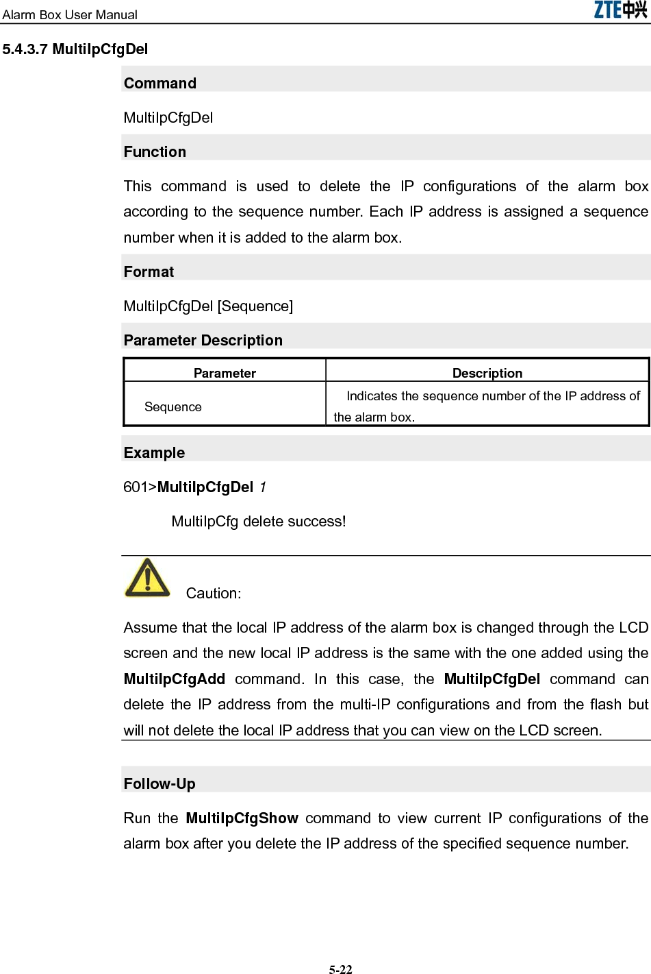
![Alarm Box User Manual 5-225.4.3.7 MultiIpCfgDel Command MultiIpCfgDel Function This command is used to delete the IP configurations of the alarm box according to the sequence number. Each IP address is assigned a sequence number when it is added to the alarm box. Format MultiIpCfgDel [Sequence] Parameter Description Parameter Description Sequence Indicates the sequence number of the IP address of the alarm box. Example 601>MultiIpCfgDel 1 MultiIpCfg delete success! Caution: Assume that the local IP address of the alarm box is changed through the LCD screen and the new local IP address is the same with the one added using the MultiIpCfgAdd command. In this case, the MultiIpCfgDel command can delete the IP address from the multi-IP configurations and from the flash but will not delete the local IP address that you can view on the LCD screen. Follow-Up Run the MultiIpCfgShow command to view current IP configurations of the alarm box after you delete the IP address of the specified sequence number.](https://usermanual.wiki/ZTE/ALARMBOX/User-Guide-1233834-Page-60.png)
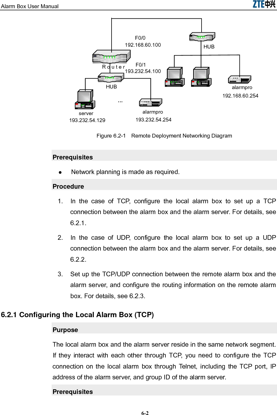
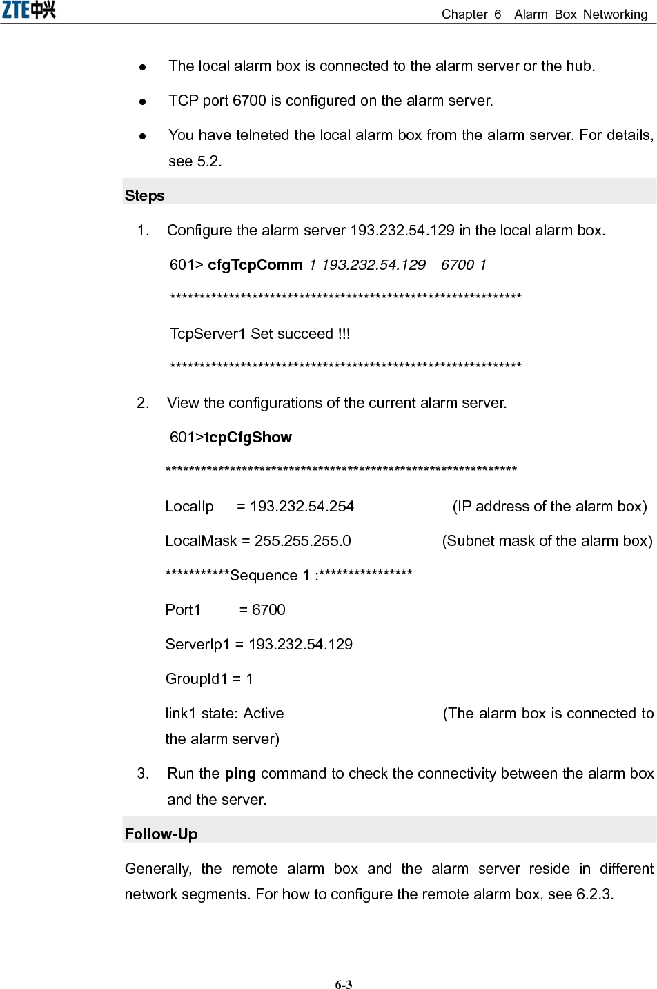
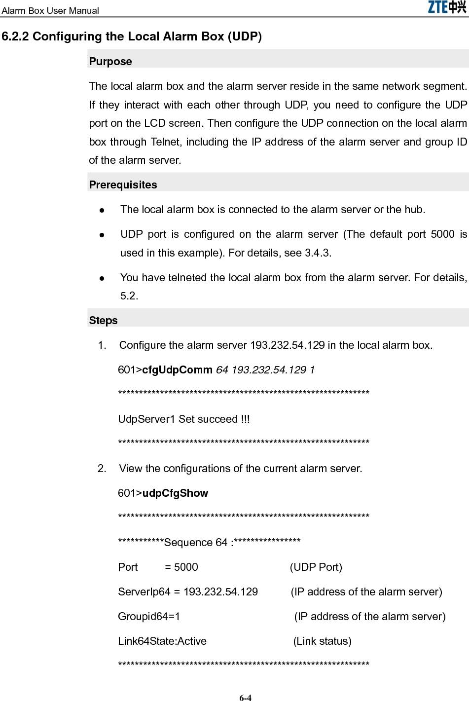
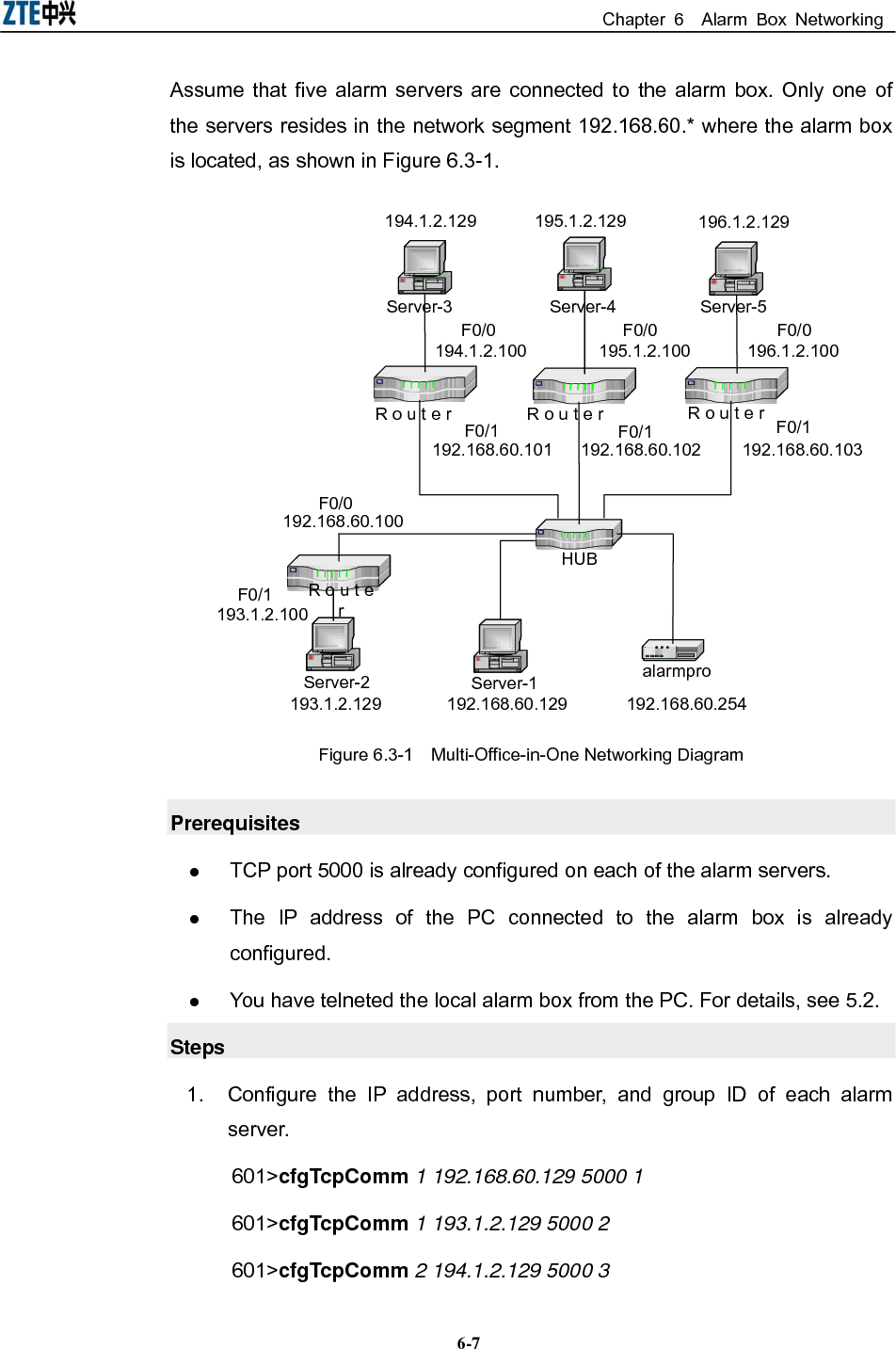
![Alarm Box User Manual 6-6601>cfgUdpComm 66 193.232.54.129 3 ************************************************************ UdpServer1 Set succeed !!! ************************************************************ 2. Check the routing information saved in the flash. 601>routeFlashShow 3. Add the necessary route from the alarm box to the router. 601>routeSave 193.232.54.129 192.168.60.100 4. Check if the routing information is added to the flash successfully. 601>routeFlashShow ***No.*********destination*************gateway***** 1 193.232.54.129 192.168.60.100 ************************************************* 5. Restart the alarm box. The routing information takes effect. 6. Telnet the alarm box from the alarm server, and then run the ping command to check the connectivity between the alarm box and the server. Follow-Up To delete the routing information, run the routeErase [Sequence] command. Here, sequence indicates the sequence number of the routing information saved in the flash. 6.3 Multi-Office-in-One Networking Purpose Multi-office-in-one means that up to 10 groups of alarm servers can be connected to an alarm box. The alarm servers may be located in different network segments. Therefore, remote deployment should be employed in the multi-office-in-one networking.](https://usermanual.wiki/ZTE/ALARMBOX/User-Guide-1233834-Page-66.png)