Users Manual

Alarm Box
User Manual
Version V5.0
ZTE CORPORATION
ZTE Plaza, Keji Road South,
Hi-Tech Industrial Park,
Nanshan District, Shenzhen,
P. R. China
518057
Tel: (86) 755 26771900
Fax: (86) 755 26770801
URL: http://ensupport.zte.com.cn
E-mail: support@zte.com.cn

LEGAL INFORMATION
Copyright © 2006 ZTE CORPORATION.
The contents of this document are protected by copyright laws and international treaties. Any reproduction or distribution of
this document or any portion of this document, in any form by any means, without the prior written consent of ZTE
CORPORATION is prohibited. Additionally, the contents of this document are protected by contractual confidentiality obligations.
All company, brand and product names are trade or service marks, or registered trade or service marks, of ZTE CORPORATION
or of their respective owners.
This document is provided “as is”, and all express, implied, or statutory warranties, representations or conditions are disclaimed,
including without limitation any implied warranty of merchantability, fitness for a particular purpose, title or non-infringement.
ZTE CORPORATION and its licensors shall not be liable for damages resulting from the use of or reliance on the information
contained herein.
ZTE CORPORATION or its licensors may have current or pending intellectual property rights or applications covering the subject
matter of this document. Except as expressly provided in any written license between ZTE CORPORATION and its licensee, the
user of this document shall not acquire any license to the subject matter herein.
ZTE CORPORATION reserves the right to upgrade or make technical change to this product without further notice.
Users may visit ZTE technical support website http://ensupport.zte.com.cn to inquire related information.
The ultimate right to interpret this product resides in ZTE CORPORATION.
Revision History
Revision No. Revision Date Revision Reason
R1.0 20091030-R1.0 First Edition
Serial Number:

Preface
About This Manual
This manual introduces the components of an alarm system and guides the
readers in installing, configuring, operating, and upgrading the alarm box.
Moreover, it provides several networking scenarios of the alarm box.
What Is in This Manual
This manual contains the following chapters:
Chapter Summary
Chapter 1 Overview Introduces the components of an alarm system and
the functions of the alarm box.
Chapter 2 Alarm Box
Installation
Introduces how to install the alarm box and how to
connect the power cable and network cable.
Chapter 3 Typographical
Conversions
Introduces how to perform initial configurations on the
alarm box.
Chapter 4 Common
Operations
Introduces the alarm box menu and some common
operations.
Chapter 5 Telnet
Commands
Introduces how to telnet the alarm box from a PC to
configure the alarm box.
Chapter 6 Alarm Box
Networking Scenarios
Introduces the typical networking scenarios of the
alarm box, including the remote deployment,
multi-office-in-one, and cross-VLAN networking.
Appendix A Alarm Box
Upgrade
Introduces how to upgrade the alarm box by using the
HyperTerminal through FTP.
Appendix B Acronyms and
Abbreviations Lists the acronyms and abbreviations.
Conventions
1. Typographical Conversions
2. Mouse Operation Conversions
Action Meaning
Click Refers to clicking the primary mouse button (usually the left
mouse button) once.
Double-click Refers to quickly clicking the primary mouse button (usually
the left mouse button) twice.
Right-click Refers to clicking the secondary mouse button (usually the
right mouse button) once.
Drag Refers to pressing and holding a mouse button and moving
the mouse.
Click Refers to clicking the primary mouse button (usually the left
mouse button) once.
Typeface Meaning
Bold Menus, menu options, function names, input
parameters, option button names, check boxes,
drop-down lists, dialog box names, window names.
Italic Variables for you supply values
Note: Provides additional information about a certain
topic.
Caution: Provides alerts about a certain topic. In this
situation, improper operations may result in equipment
damage or loss of data.
-i-
Contents
Chapter 1 Overview .................................................................................................................... 1-1
1.1 Introduction ...................................................................................................................... 1-1
1.2 Alarm System Components ............................................................................................. 1-1
1.3 Alarm Box Functions ........................................................................................................ 1-2
1.4 Technical Specifications ................................................................................................... 1-4
Chapter 2 Alarm Box Installation ................................................................................................. 2-1
2.1 Introduction ...................................................................................................................... 2-1
2.2 Installing the Alarm Box ................................................................................................... 2-1
2.3 Connecting Cables (AC Power Cable and Network Cable) ............................................. 2-4
2.4 Connecting Cables (DC Power Cable and Network Cable) ............................................. 2-6
Chapter 3 Initial Configuration .................................................................................................... 3-1
3.1 Introduction ...................................................................................................................... 3-1
3.2 Keys, Alarm Indicators, and Alarm Server Indicators ....................................................... 3-1
3.3 Icons on the LCD Screen ................................................................................................. 3-3
3.4 Configuring the Alarm Box ............................................................................................... 3-3
3.4.1 Setting the IP Address ............................................................................................ 3-4
3.4.2 Setting the Subnet Mask ......................................................................................... 3-6
3.4.3 Setting the UDP Port .............................................................................................. 3-6
Chapter 4 Common Operations .................................................................................................. 4-1
4.1 Introduction ...................................................................................................................... 4-1
4.2 Setting Alarm Box Functions ............................................................................................ 4-1
4.3 Viewing Alarm Statistics ................................................................................................... 4-3
4.4 Setting the Broadcast Storm Threshold ........................................................................... 4-4
4.5 Setting the Sound Volume ............................................................................................... 4-5
4.6 Setting Permanent Mute .................................................................................................. 4-5
4.7 Acknowledging Alarms on a per-Group Basis .................................................................. 4-6
Chapter 5 Telnet Commands ...................................................................................................... 5-1
5.1 Introduction ...................................................................................................................... 5-1
-ii-
5.2 Getting Started .................................................................................................................. 5-1
5.3 Man-Machine Command Format ...................................................................................... 5-3
5.4 Command Description ...................................................................................................... 5-4
5.4.1 Basic Commands .................................................................................................... 5-4
5.4.2 Routing-Related Commands ................................................................................. 5-13
5.4.3 VLAN-Related Commands .................................................................................... 5-17
Chapter 6 Alarm Box Networking Scenarios ................................................................................ 6-1
6.1 Introduction ....................................................................................................................... 6-1
6.2 Remote Deployment Networking Scenario ....................................................................... 6-1
6.2.1 Configuring the Local Alarm Box (TCP) ................................................................... 6-2
6.2.2 Configuring the Local Alarm Box (UDP) .................................................................. 6-4
6.2.3 Configuring the Remote Alarm Box ......................................................................... 6-5
6.3 Multi-Office-in-One Networking ......................................................................................... 6-6
6.4 Cross-VLAN Networking ................................................................................................. 6-10
-i-
Figures
Figure 2.2-1 Hanging Board .......................................................................................................... 2-2
Figure 2.2-2 Alarm Box Installation 1 .......................................................................................... 2-3
Figure 2.2-3 Alarm Box Installation 2 .......................................................................................... 2-3
Figure 2.3-1 Top View (Left) and Side View (Right) of the AC Adaptor .................................. 2-5
Figure 2.3-2 AC Power Cable ....................................................................................................... 2-5
Figure 3.4-1 Alarm Box Main Menu ............................................................................................. 3-4
Figure 3.4-2 Parameter Setting Sub-Menu ................................................................................. 3-5
Figure 3.4-3 Setting the IP Address ............................................................................................. 3-5
Figure 4.2-1 Alarm Box Menu ....................................................................................................... 4-2
Figure 4.3-1 Alarm Statistics Example ........................................................................................ 4-3
Figure 6.2-1 Remote Deployment Networking Diagram ........................................................... 6-2
Figure 6.3-1 Multi-Office-in-One Networking Diagram .............................................................. 6-7
Figure 6.4-1 Cross-VLAN Networking Diagram ....................................................................... 6-11
-i-
Tables
Table 2.4-1 DC Power Cable Parameters 2-6
Table 3.2-1 Key Functions 3-1
Table 3.2-2 Alarm Indicator Meanings 3-2
Table 3.2-3 Alarm Indicator Statuses 3-2
Table 3.2-4 Alarm Server Indicator Meanings, Link Statues, and Alarm Statuses 3-2
Table 3.3-1 Icon Description 3-3
Table 5.2-1 Command Description 5-2
Table 5.3-1 Command Format Convensions 5-3
1-1
Chapter 1 Overview
1.1 Introduction
Description
This chapter introduces the components of an alarm system and the functions
of the alarm box that can prompt alarms by sounds or lights or forward them to
appropriate personnel through short messages.
Contents
Topic Section
Alarm System Components 1-1
Alarm Box 1-2
Technical Specifications 1-4
1.2 Alarm System Components
Description
The alarm system enables users to learn the faults occurring to devices at any
time. If a device is faulty or runs improperly, it sends alarm information to the
alarm server that not only presents current or history alarms but also forwards
alarms to the alarm box in real time. The alarm box generates sounds or lights
to prompt the received alarms of different severities and forwards alarm
information to pre-set mobile phone number if necessary.
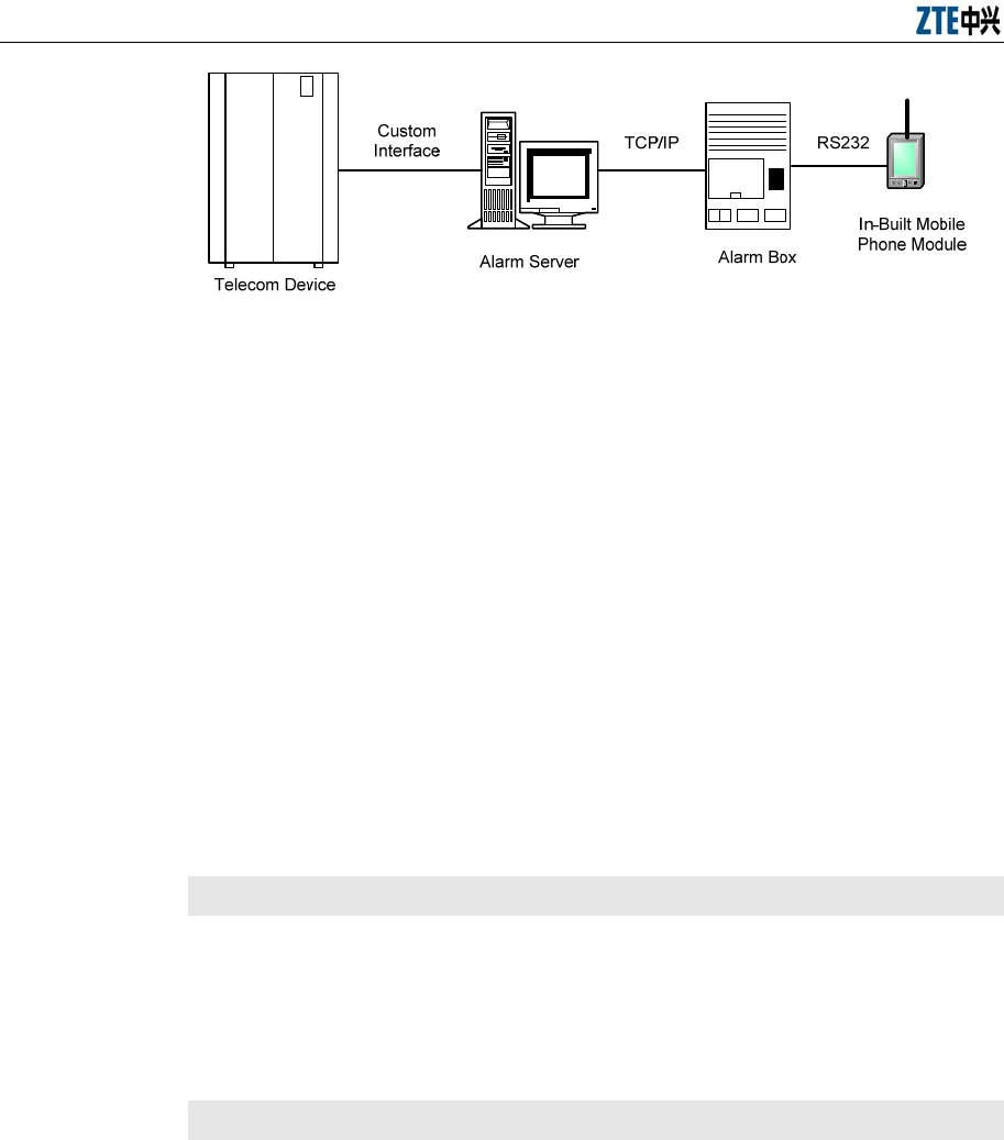
Components
The alarm system consists of two components, namely the alarm server (generally
it is an OMC server) and the alarm box, as shown in Figure 1.2-1.
Alarm Box User Manual
1-2
TCP/IP
告警服务器
告警箱内置的手
机模块
RS232自定义接口
告警箱
电信设备
Figure 1.2-1 Alarm System
The alarm server allows users to determine the severities of alarms to
be forwarded to the alarm box as well as the mobile phone number to
which the alarm box sends alarm short messages.
The alarm server transfers alarm messages to the alarm box through
TCP/IP. The mobile phone module of the alarm box sends alarms to the
specified mobile number through short messages.
Alarms are not only presented on the LCD screen of the alarm box but
also prompted by the alarm indicator, alarm server indicator, and
sounds.
1.3 Alarm Box Functions
Description
The alarm box is connected with an alarm server through HUB or a layer-2
switch. The alarm box presents different severities of alarm data sent from the
server in various ways, for example, on the LCD screen, through indicators,
and by generating sounds.
Functions
Alarm short message sending: The alarm server can be configured to
interact with the in-built mobile phone module of the alarm box, enabling
the alarm box to send alarm short messages to the specified mobile
number of a maintainer. The alarm box sends alarm short messages
based on the severities to CDMA or GSM subscribers (however, CDMA
and GSM cannot be supported simultaneously).
Sound prompt: The in-built speaker produces voice or buzzer alarms to

Chapter 1 Overview
1-3
prompt the received alarms and the alarm severities.
Alarm indicator: The four alarm severities are represented by different
colors, namely yellow, orange, blue, and red (listed from high to low).
Alarm server indicator: The alarm box panel provides 10 alarm server
indicators representing 10 group of alarm servers (generally it is
recommended that one indicator represent one server). Each indicator
shows the link status and the alarm status for a specific group of server
servers.
LCD display: The alarm information sent from the alarm server is
displayed on the LCD screen of the alarm box. Moreover, the alarm box
menu and keys on the panel are available to configure the working
parameters, for example, the IP address, UDP port, key tone control,
and backlight control.
Remote deployment: An alarm server can be connected to both local
and remote alarm boxes. In the case of remote alarm boxes, routing
information should be configured in the alarm box. Remote deployment
allows more flexible usages of alarm boxes. For example, the alarm box
can be deployed in the office rather than in the equipment room.
Multi-office-in-one: Up to 128 alarm servers can be configured on an
alarm box, and up to 10 groups of alarm servers can be simultaneously
connected to an alarm box. The alarm servers may reside in different
network segments, and therefore the multi-office-in-one function is
employed together with the remote access function.
Cross-VLAN alarming: The alarm box can be simultaneously connected
to alarm servers from different VLANs. In this scenario, a layer-2 switch
rather than a layer-3 device is deployed to achieve VLAN isolation,
reducing the networking cost.
Broadcast storm detection and alarming: Thresholds can be configured
to detect the network status and avoid network congestion caused by
data broadcasting.
Group-based alarm acknowledgement: Alarms can be acknowledged on
a per-group basis as alarm servers can be classified into groups, and

Alarm Box User Manual
1-4
each group of alarm servers is represented by an alarm server indicator.
Alarm statistics query: The alarm box can show the statistics of alarms
reported by each alarm server on the LCD screen.
Permanent mute: Alarm prompts can be muted based on the alarm
severity.
Remote access: The alarm box supports Telnet-based remote access.
Users can telnet the alarm box to configure relevant parameters by
using man-machine commands. The alarm box supports the
configurations concerning alarm servers, routing, VLAN, short message
transfer, system time, and so on.
1.4 Technical Specifications
Dimensions: 323mm×220mm×58mm (LxWxD)
Power supply: -48 V DC or 90 V - 264 V AC (an power adapter is required for
AC power)
Power: 40W
Interface: one RJ-45 network interface
Environmental temperature: 0 ℃- 45℃
2-1
Chapter 2 Alarm Box Installation
2.1 Introduction
Description
This chapter briefly introduces how to install the alarm box and how to connect
the power cable and the network cable. The alarm box should be placed in a
distinctive location for maintainers’ convenience.
The alarm box supports both AC and DC power supplies.
Contents
Topic Section
Installing the Alarm Box 2-1
Connecting Cables (AC Power Cable
and Network Cable) 2.3
Connecting Cables (DC Power Cable
and Network Cable) 2.4
2.2 Installing the Alarm Box
Purpose
The alarm box is installed in the control room or in the office. It presents
maintainers with alarms of different severities. The alarm box should be placed
in a distinctive location so that maintainers can easily notice the alarm prompts
or hear the alarm sounds. The following aspects should be taken into
considerations so as to install the alarm box at an appropriate height: the
actual situation of the project site, the length of the power cable, the location of
the AC adaptor, and the location of any other alarm box.
Prerequisites
Tools and instruments are ready.
The installation location of the alarm box is determined.
The hanging board is already uninstalled from the back of the alarm box.
Steps
Alarm Box User Manual
2-2
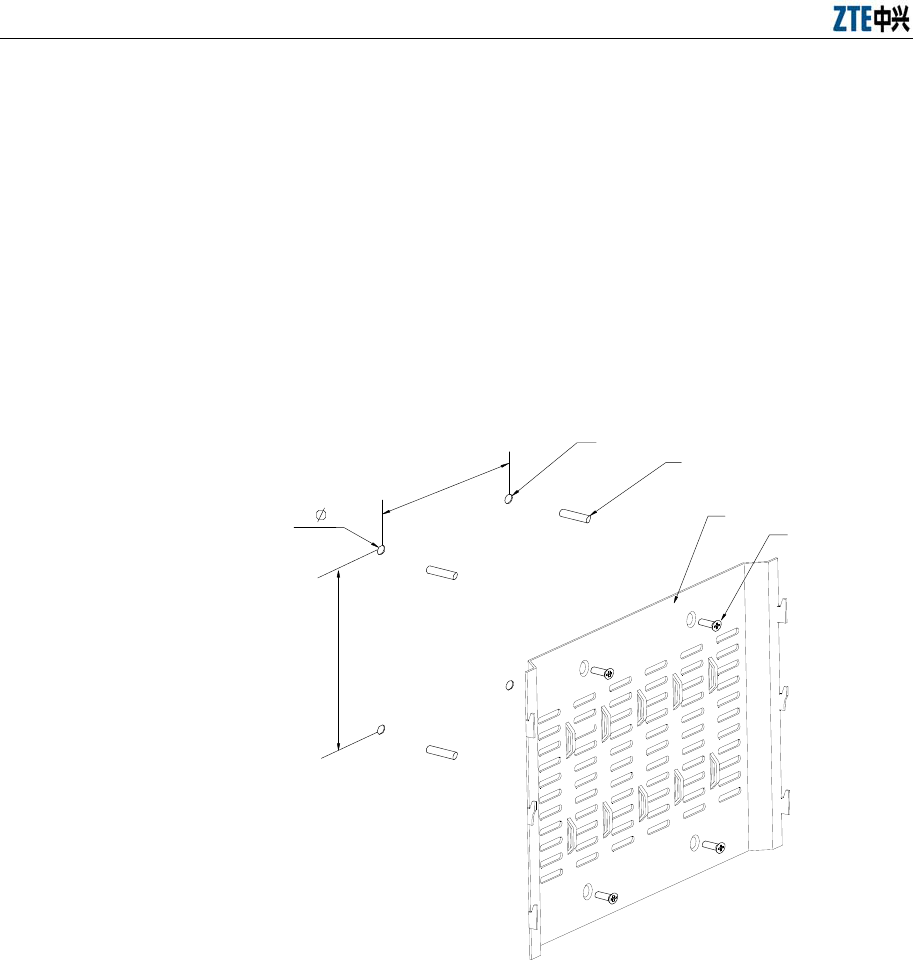
1. Hold the hanging board up against the wall and mark the positions of
installation holes. Alternatively, you can draw lines according to the size
shown in Figure 2.2-1.
2. Drill 4 holes of φ8 at the marked positions, and each hole is 40mm deep.
3. Hammer lightly the plastic expansion tubes into the holes. Make sure
that the expansion tubes are completely fastened in the holes.
4. Fix the hanging board on the wall with 4 M5 countersunk head wood
screws, as shown in Figure 2.2-1.
1
2
120
140
4- 8 3
4
1. Φ8 hole 2. Plastic expansion tube 3. Hanging board 4. M5 countersunk head wood screw
Figure 2.2-1 Hanging Board
5. Hook the alarm box on to the hanging board, with the hanging holes
exactly matching the hooks of the board. as shown in Figure 2.2-2 and
Figure 2.2-3.
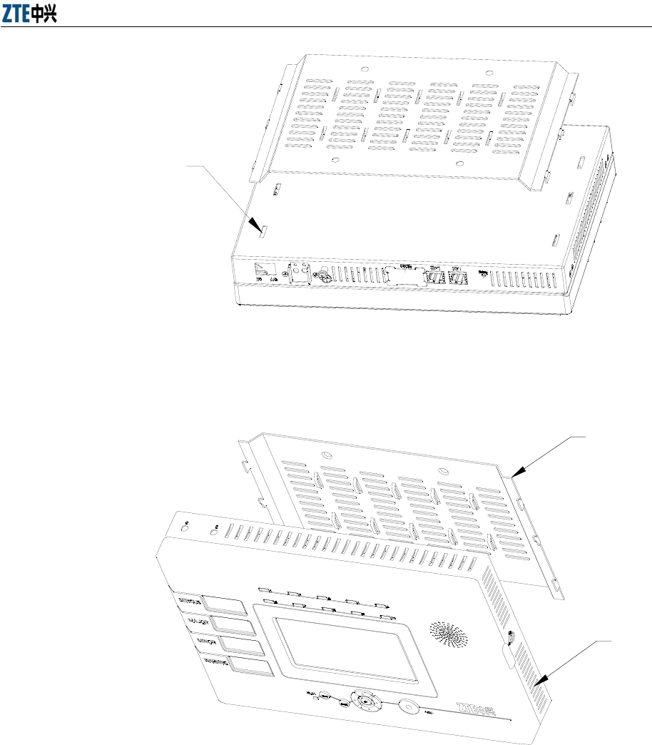
Chapter 2 Alarm Box Installation
2-3
1
1. Hanging hole
Figure 2.2-2 Alarm Box Installation 1
2
1
1. Hanging board .2. Alarm box
Figure 2.2-3 Alarm Box Installation 2
6. Lock the alarm box. A locked alarm box cannot be separated from the
hanging board.

Alarm Box User Manual
2-4
2.3 Connecting Cables (AC Power Cable and Network Cable)
Purpose
In the case of AC power supply, the AC adaptor should be used and there
should be an AC power supply socket near the alarm box. The AC adaptor
delivered with the alarm box provides a 2-meter-long DC power cable, and the
AC power cable is also 2 meter long. The location of AC adaptor and the length
of the power cables should be considered when the alarm box is installed.
The power cables and network cable should be fixed on the wall after they are
covered by jackets. Cabling should be done with smooth bends. The cables
may be damaged if the ends of the cables are tightened.
Prerequisites
The alarm box is installed.
The power cable and network cable are prepared and laid well.
Tools and instruments are ready.
Steps
1. Connect the straight-through cable (RJ-45 connector) to the network
interface of the alarm box, and then connect the other end to the port of
the hub or to the layer-2 switch that resides in the same LAN with the
alarm server.
2. Connect the three-pole plug of the AC power cable to the AC power
supply socket, and then connect the any end of the power cable to the
AC adaptor. Make sure that the AC power supply socket is switched off
before you connect cables to it.
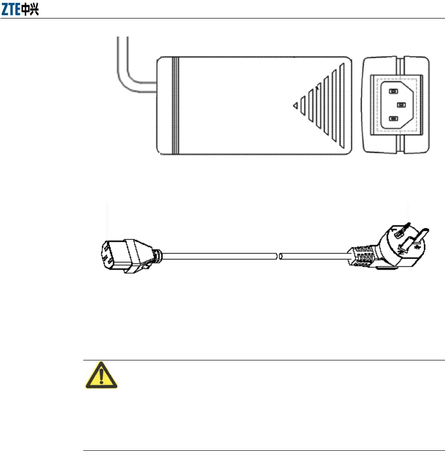
Chapter 2 Alarm Box Installation
2-5
Figure 2.3-1 Top View (Left) and Side View (Right) of the AC Adaptor
Figure 2.3-2 AC Power Cable
Caution:
The three-pole plug actually used may differ from that in the preceding figure
due to the different standards adapted by countries. Appropriate power cables
will be delivered with the alarm box; otherwise a junction board can be used.
3. Connect the DC power cable of the adaptor to the power supply terminal
that is in the right part of the bottom panel of the alarm box. Connect the
bare wire marked with GND to the -48VRTN terminal block of the power
supply terminal. Connect the other bare wire to the -48V terminal block.
Then fix the bare wires with in-built bolts.
4. According to the installation location of the alarm box and the layout of
the cables, install the PVC cable tray on the wall.
If the other ends of the cables need to be placed at the same place (for
example, inside the cabinet). Lay the PVC cable tray along the wall to
the wiring ladder and then to the cabinet (upper cabling method).
Alarm Box User Manual
2-6
Otherwise, lay the PVC cable tray along the wall to the floor, and then
lay the cables along the cable rack under the floor to the cabinet (down
cabling method where the cable tray may not be used in cabling under
the floor).
If the other ends of the cables need to be placed at the same place,
separate the cables in proper position. Moreover, put them into narrow
PVC cable trays, and lay them along the wall or along the cable racks
under the floor to the proper positions.
5. Put the power cables and the network cable into a bigger PVC cable tray.
After cabling is complete, close the top cover of the PVC cable tray.
Caution:
It may be unable to hide the AC adaptor somewhere. However, you can put it in
a safe place in the project site.
2.4 Connecting Cables (DC Power Cable and Network Cable)
Purpose
The alarm box can be connected to the DC power supply available by using
the 3-meter-long DC power cable delivered with the alarm box or a self-made
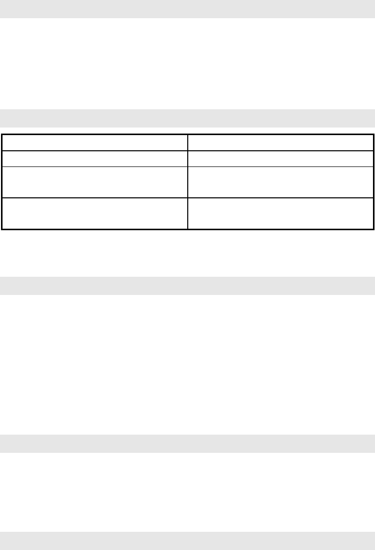
cable. The parameters of the self-made cable should comply with or be higher
than those of the delivered cable, as shown in Table 2.4-1.
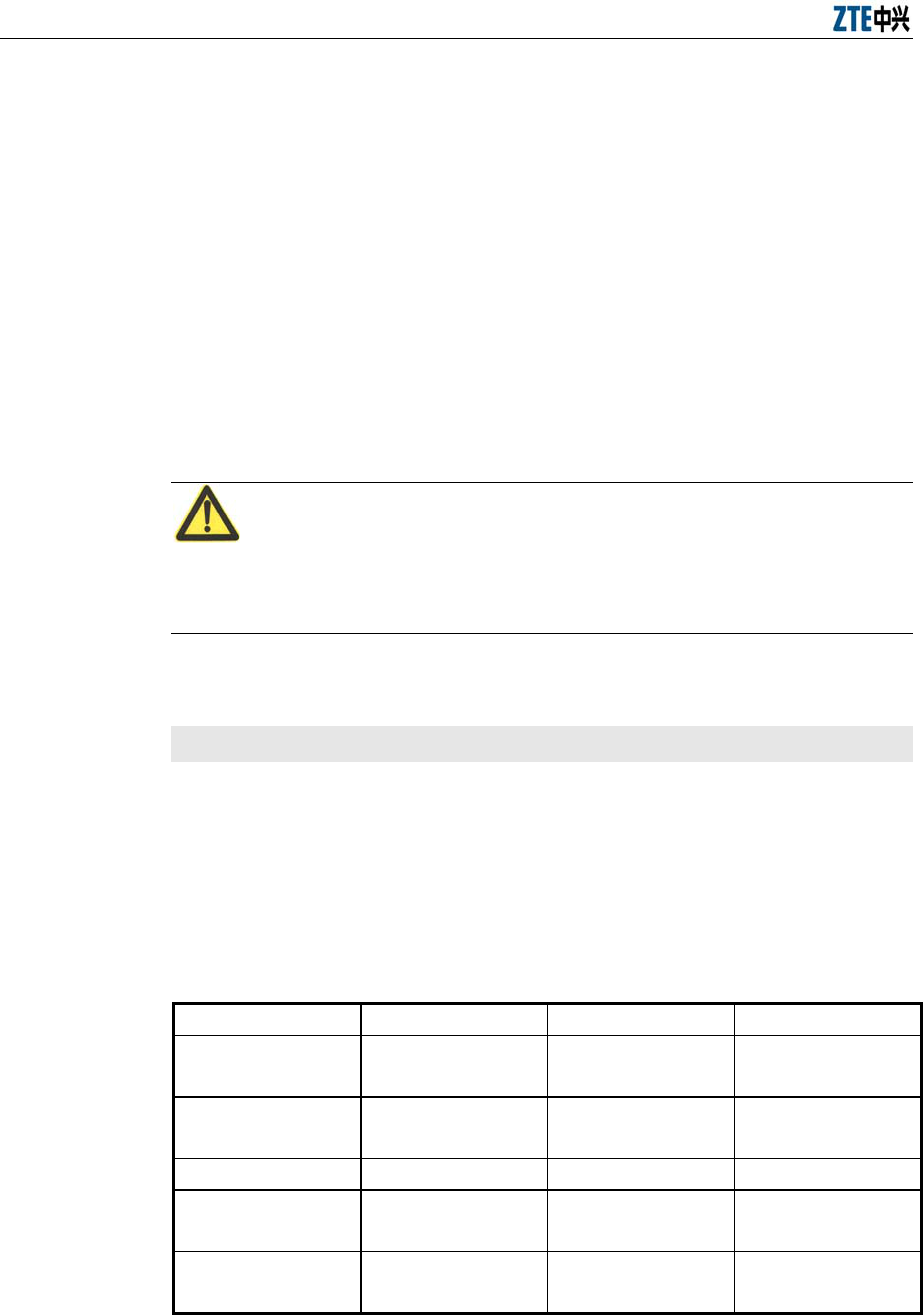
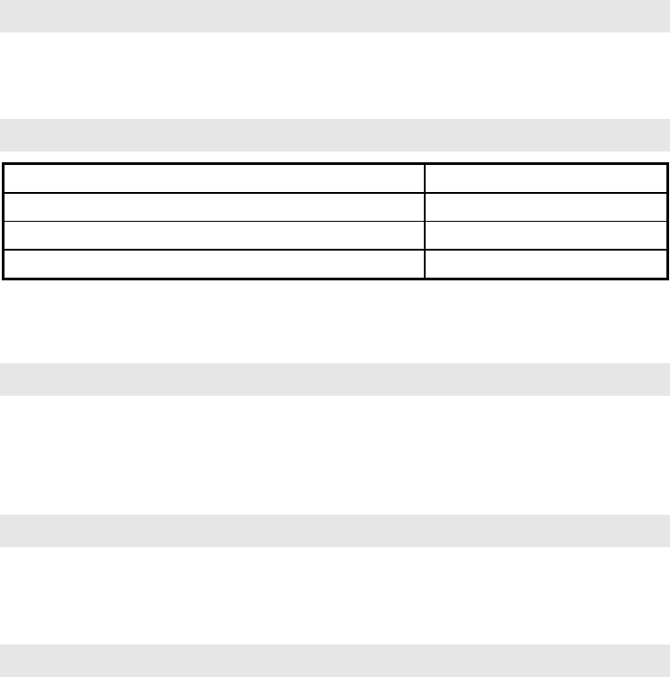
Table 2.4-1 DC Power Cable Parameters
Parameter Value Parameter Value
Nominal
cross-sectional area 1mm2 Jacket thickness 0.87mm
Outer diameter 1.3mm Outer diameter of
the jacket 6.94mm
Isolation thickness 0.65mm Rated voltage 300/500V
Outer insulation
diameter 2.6mm Critical
temperature 70℃
The maximum DC
resistance at 20℃ 20Ω/km N/A N/A

Chapter 2 Alarm Box Installation
2-7
The power cable and network cable should be fixed on the wall after they are
covered by jackets. Cabling should be done with smooth bends. The cables
may be damaged if the ends of the cables are tightened.
Prerequisites
The alarm box is installed.
The power cable and network cable are prepared and laid well.
Tools and instruments are ready.
Steps
1. Connect the straight-through cable (RJ-45 connector) to the network
interface of the alarm box, and then connect the other end to the port of
the hub or the layer-2 switch that resides in the same LAN with the alarm
server.
2. Connect the DC power cable to the power supply terminal that is in the
right part of the bottom panel of the alarm box. Connect a wire (generally
it is a black wire) to the -48VRTN terminal block of the power supply
terminal. Connect the other wire (generally it is a blue one) to the -48V
terminal block. Then fix the wires with in-built bolts. Make sure that the
other end of the power cable is connected to the DC power supply
correctly.
3. According to the installation location of the alarm box and the layout of
the cables, install the PVC cable tray on the wall.
If the other ends of the cables need to be placed at the same place (for
example, inside the cabinet). Lay the PVC cable tray along the wall to
the wiring ladder and then to the cabinet (upper cabling method).
Otherwise, lay the PVC cable tray along the wall to the floor, and then
lay the cables along the cable rack under the floor to the cabinet (down
cabling method where the cable tray may not be used in cabling under
the floor)..
If the other ends of the cables need to be placed at the same place,
separate the cables in proper position. Moreover, put them into narrow
PVC cable trays, and lay them along the wall or along the cable racks
under the floor to the proper positions.

Alarm Box User Manual
2-8
4. Put the power cables and the network cable into a bigger PVC cable tray.
After cabling is complete, close the top cover of the PVC cable tray.
3-1
Chapter 3 Initial Configuration
3.1 Introduction
Description
This chapter introduces the initial settings of the alarm box and alarm servers.
For example, the alarm box allows users to configure its IP address and port as
well as IP addresses of alarm servers through its LCD screen; users can set
the alarm forwarding parameters on alarm servers.
Contents
Topic Section
Keys, Alarm Indicators, and Alarm Server
Indicators 3.2
Icons on the LCD Screen 3.3
Configuring the Alarm Box 3.4
3.2 Keys, Alarm Indicators, and Alarm Server Indicators
Keys
Users can press keys on the alarm box to view alarm information or configure
settings on the LCD screen. Table 3.2-1 describes the functions provided by
the keys.
Table 3.2-1 Key Functions
Key Function
Cancel Returns to the previous menu.
OK Confirms the operation result.
Menu Opens the main menu.
ACK Acknowledges the alarms reported by alarm servers.
▲▼ Moves the cursor up or down on the menu or modify the parameter
values, such as the IP address and UDP port.
◄ ► Moves the cursor left or right.
Reset Resets the alarm box.
Alarm Box User Manual
3-2
Alarm Indicators
The alarm box panel provides 4 alarm indicators representing 4 different
severities of alarm information. Table 3.2-2 and Table 3.2-3 lists the meanings
and statuses of the indicators respectively.
Table 3.2-2 Alarm Indicator Meanings
Alarm Indicator Description
SERIOUS Red
Indicates the critical alarms (Severity 1).
MAJOR Blue
Indicates the major alarms (Severity 2).
MINOR Orange
Indicates the minor alarms (Severity 3).
WARNING Yell ow
Indicates the warning alarms (Severity 4).
Table 3.2-3 Alarm Indicator Statuses
Status Description
Blink Indicates alarms are generated but not acknowledged yet.
Light on Indicates alarms are generated and acknowledged.
Light off Indicates no alarm.
Alarm Server Indicators
The alarm box panel provides 10 alarm server indicators representing 10
groups of alarm servers connected to the alarm box. Each indicator shows the
link status and alarm status. Table 3.2-4 lists the meanings, the link statuses,
and alarm statues represented by the indicators.
Table 3.2-4 Alarm Server Indicator Meanings, Link Statues, and Alarm Statuses
Indicator Status Description
Red
Blink Indicates new alarms are generated but not
acknowledged yet.
Light on Indicates new alarms are generated and
acknowledged.
Yellow Blink Indicates no alarm is generated recently and
Chapter 3 Initial Configuration
3-3
Indicator Status Description
the alarm server interacts with the alarm box
properly.
Light on Indicates the alarm server is disconnected
from the alarm box.
Note: If the indicator lights off, it indicates that the alarm server is not configured yet.
3.3 Icons on the LCD Screen
Icons on the LCD screen allow users to operate and configure the alarm box.
Table 3.3-1 lists the icons available on the LCD screen.
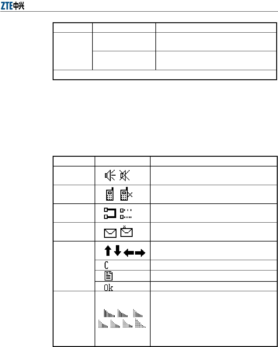
Table 3.3-1 Icon Description
Name Icon Meaning
Alarm
sound
Indicates whether the alarm box generates
sounds when it receives alarms.
Mobile
phone
Indicates the working status of the mobile
phone module.
Network
connection
Indicates whether the alarm box is connected
to alarm servers.
Short
message
Indicates whether the short messages are sent
successfully.
Key
Indicates the direction keys “Up”, “Down”,
“Left”, and “Right”.
Indicates the Cancel key.
Indicates the Menu key.
Indicates the OK Key.
Mobile
signal
Indicates the mobile signal strength.
The first icon consisting of all solid lines
indicates the strongest mobile signal while the
last one indicates the weakest signal.
This icon is displayed only after the mobile
card is inserted into the alarm box.
3.4 Configuring the Alarm Box
The IP address, subnet mask, and UDP port of the alarm box can be
configured on the LCD screen. If the alarm box interacts with the alarm server
through TCP, the TCP port should be configured on the alarm server.
Alarm Box User Manual
3-4
3.4.1 Setting the IP Address
Purpose
The default IP address of the alarm box is 128.0.0.127. The alarm box and the
alarm server should reside in the same network segment (for example, the
server IP address is 192.176.120.129, and thus the alarm box IP address is
192.176.120.254). Otherwise, a router needs to be deployed between them
and routing information should be configured in the alarm box. For details, see
6.2 and 6.3.
Prerequisites
The IP address of the alarm server is already known and network
planning is made accordingly.
The alarm box is connected to the alarm server through the network
cable.
Steps
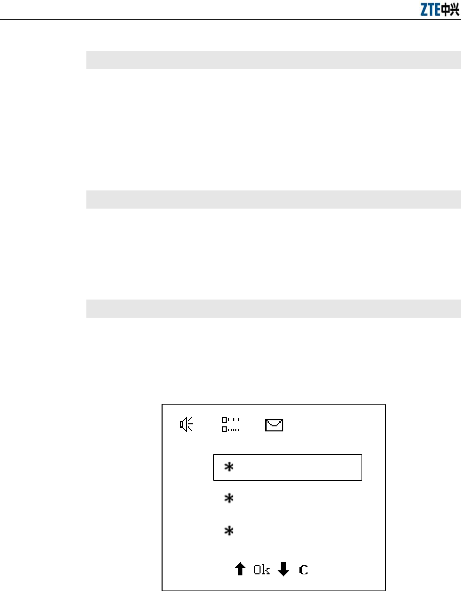
1. On the alarm box panel, press Menu. The main menu appears on the
LCD screen.
2. Select Parameter Set by pressing ▲ or ▼, as shown in Figure 3.4-1.
Parameter Set
Lang. Select
Statistics Query
Figure 3.4-1 Alarm Box Main Menu
3. Press OK. The parameter setting sub-menu appears, as shown in Figure
3.4-2.
Chapter 3 Initial Configuration
3-5
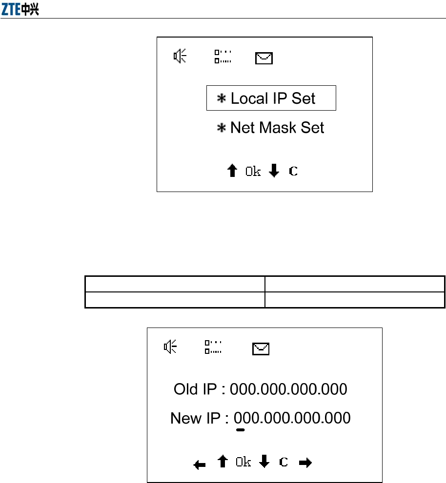
Figure 3.4-2 Parameter Setting Sub-Menu
4. Select Local IP Set and press OK. The IP address setting page
appears.
Use the existing IP address Step 5
Set a new IP address Step 6
Figure 3.4-3 Setting the IP Address
5. To use the existing IP address, press Cancel to return to the previous
menu.
6. To set a new IP, follow the steps below:
1) Move the cursor to the IP address field to be modified by pressing
◄ or ►.
2) Press ▲ or ▼ to modify the field.
Alarm Box User Manual
3-6
3) Press OK to validate the new settings.
3.4.2 Setting the Subnet Mask
Purpose
The subnet mask of the alarm box needs to be configured. The default value is
255.0.0.0.
Prerequisites
The alarm box is connected to the alarm server through the network
cable.
Steps
1. On the alarm box panel, press Menu. The main menu appears on the
LCD screen.
2. Select Parameter Set > Net Mask Set. The subnet mask setting page
appears.
By default, the subnet mask is 5000.
Use the existing subnet mask Step 3
Set a new subnet mask Step 4
3. To use the existing subnet mask, press Cancel to return to the previous
menu.
4. To set a new subnet mask, follow the steps below:
1) Move the cursor to the subnet mask field to be modified by pressing
◄ or ►.
2) Press ▲ or ▼ to modify the field.
3) Press OK to validate the new settings.
3.4.3 Setting the UDP Port
Purpose
The UDP port needs to be configured on the alarm box if the alarm box
interacts with the alarm server through UDP. The default UDP port is 5000.
Prerequisites

Chapter 3 Initial Configuration
3-7
The alarm box is connected to the alarm server through the network
cable.
Steps
1. In the alarm box panel, press Menu. The main menu appears on the
LCD screen.
2. Select Parameter Set > UDP link Port. The UDP setting page appears.
By default, the UDP port is 5000.
Use the existing UDP port Step 3
Set a new UDP port Step 4
3. To use the existing UDP port, press Cancel to return to the previous
menu.
4. To set a new UDP port, follow the steps below:
1) Move the cursor to the UDP port field to be modified by pressing ◄
or ►.
2) Press ▲ or ▼ to modify the field.
3) Press OK to validate the new settings.
4-1
Chapter 4 Common Operations
4.1 Introduction
Description
This chapter introduces what operations a user can perform on the LCD screen
of the alarm box.
Contents
Topic Section
Setting Alarm Box Functions 4.2
Viewing Alarm Statistics 4.3
Setting the Broadcast Storm Threshold 4.4
Setting the Sound Volume 4.5
Setting Permanent Mute 4.6
Acknowledging Alarms on a per-Group
Basis 4.7
4.2 Setting Alarm Box Functions
Purpose
The alarm box prompts faults or other information of the current network in
different ways such as sound, light, LCD display, and short messages.
Prerequisites
The alarm box is connected to the alarm server and basic configurations
are already performed on the alarm box. For details, see Chapter 3.
Steps
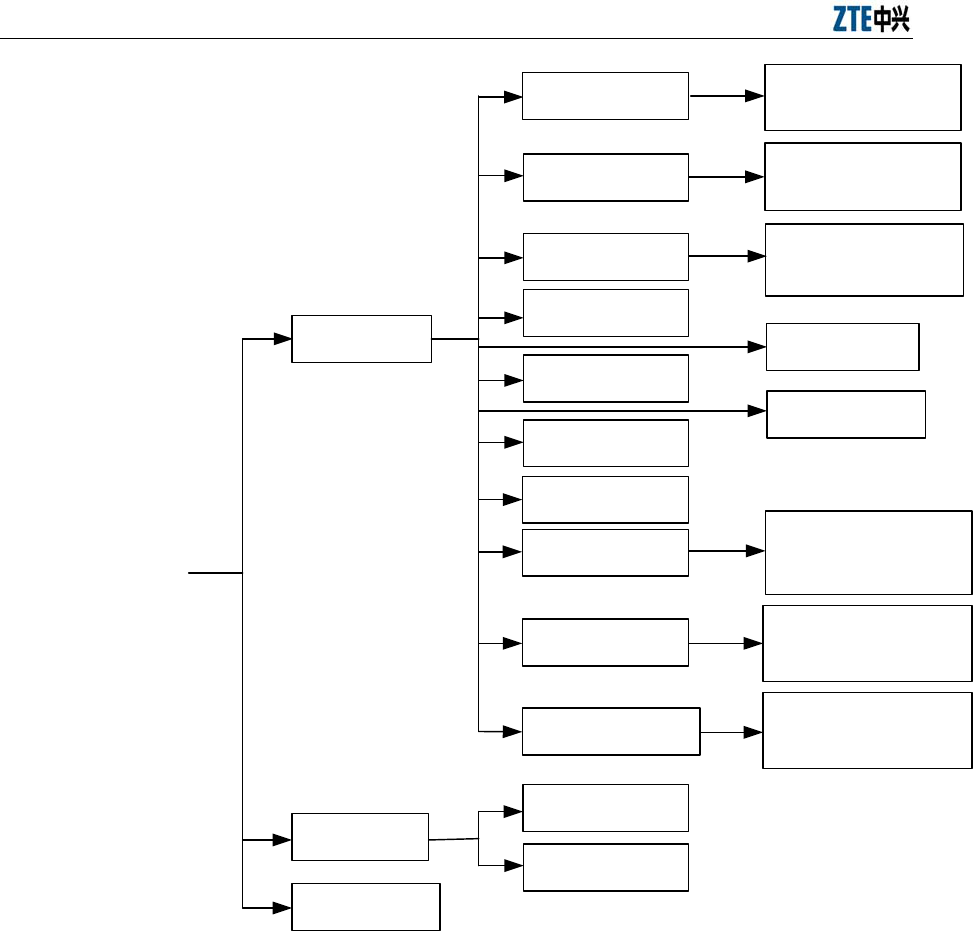
1. On the alarm box panel, press Menu. The main menu appears on the
LCD screen.
Figure 4.2-1 shows the structure of the alarm box menu.
Alarm Box User Manual
4-2
Parameter Set
Lang. Select
Net Mask Set
English Menu
Chinese Menu
Old Mask : *****
New Mask : *****
UDP link Port Old UDP Port : *****
New UDP Port : *****
Key Tones Set
Key Tones Close
Light Auto Shut
Light Always On
Volume Control
Statistics Query
Local IP Set Old IP : *.*.*.*
New IP : *.*.*.*
Alarm Tone Mode
P mute Set
Alarm Group Affirm
NetStorm Gate Old Gate value : *****
New Gate value : *****
Old Mute Level : *
New Mute Level : *
Old Group SureID : **
New Group SureID : **
Figure 4.2-1 Alarm Box Menu
2. Navigate to the alarm box parameters that you need to modify according
the preceding menu.
The common operations are listed as follows:
Viewing alarm statistics. For details, see 4.3.
Setting the broadcast storm threshold. For details, see 4.4.
Setting the sound volume. For details, see 4.5.
Setting permanent mute. For details, see 4.6.
Chapter 4 Common Operations
4-3
Acknowledging alarms on a per-group basis. For details, see 4.7.
3. Press OK to validate the new settings.
4.3 Viewing Alarm Statistics
Purpose
The alarm box can make statistics of received alarms and display the statistics
on the LCD screen.
Prerequisites
The alarm box is connected to the alarm server and basic configurations
are already performed on the alarm box. For details, see Chapter 3.
Steps
1. On the alarm box panel, press Menu. The main menu appears on the
LCD screen.
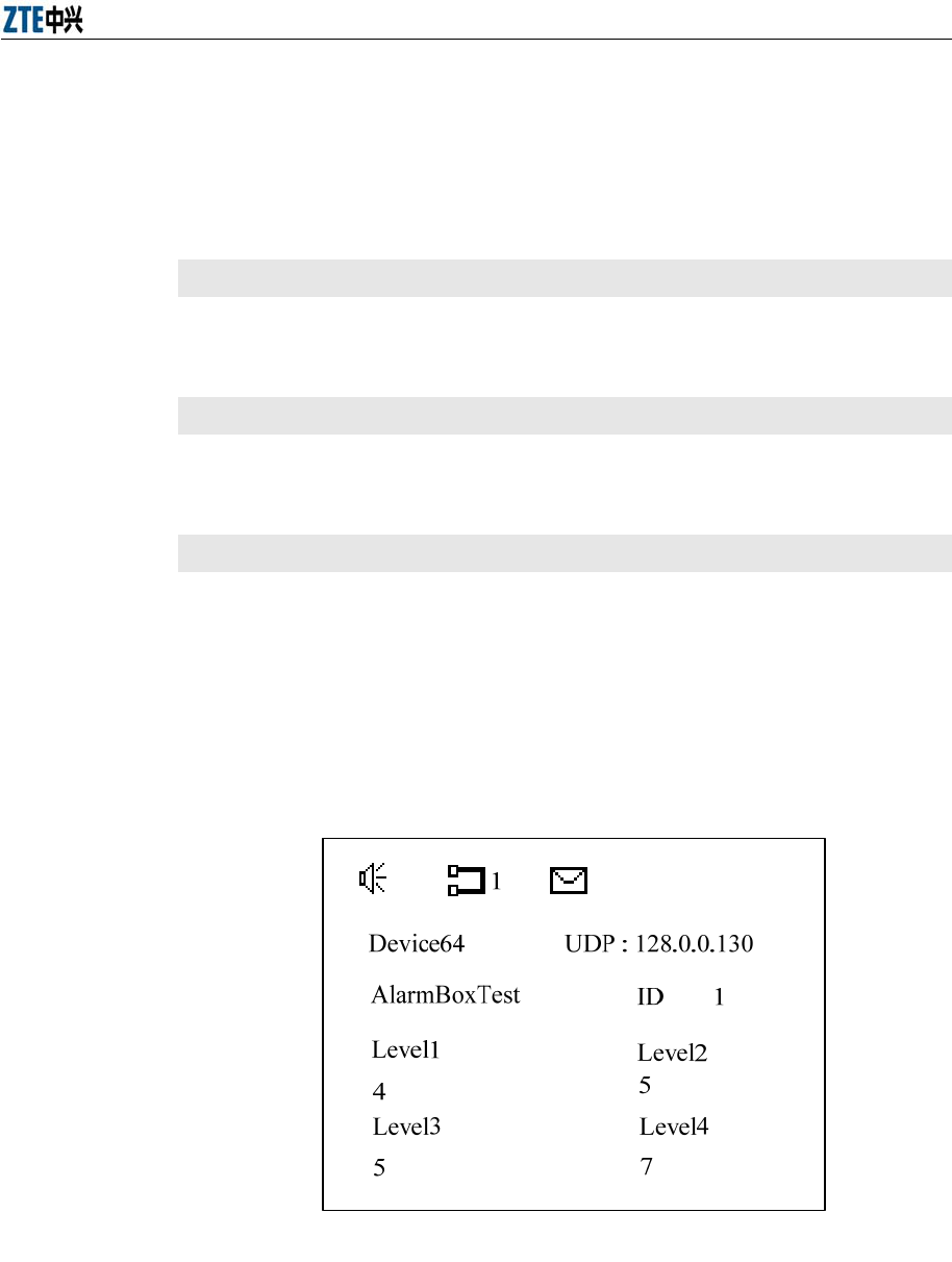
2. Select Statistics Query and press OK to view the latest alarm statistics.
If no statistics is generated, the system prompts “No Statistics Data!
Push C to Return!” Figure 4.3-1 shows an example of the alarm
statistics.
Figure 4.3-1 Alarm Statistics Example
Alarm Box User Manual
4-4
Note:
The number besides the icon denotes how many alarm servers are now
connected to the alarm box.
3. Press ▲ or ▼ to view the alarm statistics of different alarm servers.
4.4 Setting the Broadcast Storm Threshold
Purpose
Broadcast storm detection judges whether the received broadcast packets
exceed the threshold. The sampling value is generated per second. If five
consecutive sampling values exceed the specified threshold, the alarm box
considers that a broadcast storm occurs in the network. In the case of a
broadcast storm, the alarm box generates a sound or light alarm and stops
receiving broadcast packets accordingly. After a period of time, the alarm box
resumes receiving the broadcast packets. If 30 consecutive sampling values
are all lower than the threshold, the alarm box considers that the network
operates properly.
Prerequisites
The alarm box is connected to the alarm server and basic configurations
are already performed on the alarm box. For details, see Chapter 3.
Steps
1. On the alarm box panel, press Menu. The main menu appears on the
LCD screen.
2. Select Parameter Set > NetStorm Gate. The broadcast storm threshold
page appears, showing the default threshold 200.
3. Set the broadcast storm threshold according to the actual situation.
1) Move the cursor to the threshold field to be modified by pressing ◄
or ►.
2) Press ▲ or ▼ to modify the field.
4. Press OK to validate the new settings.

Chapter 4 Common Operations
4-5
4.5 Setting the Sound Volume
Purpose
The alarm box can generate voice prompts or buzzer sounds to alert users to
handle received alarms. The alarm severities requiring sound prompts can be
specified on the alarm server.
Prerequisites
The alarm box is connected to the alarm server and basic configurations
are already performed on the alarm box. For details, see Chapter 3.
Steps
1. On the alarm box panel, press Menu. The main menu appears on the
LCD screen.
2. Select Parameter Set > Volume Control. The sound volume control
page appears, showing the current volume.
3. Press ▲ or ▼ to increase or decrease the sound volume.
4. Press OK to validate the new settings.
4.6 Setting Permanent Mute
Purpose
The alarm box supports alarm-severity-based permanent mute. Alarms are
classified into four severities, namely SERIOUS, MAJOR, MINOR, and
WARNING (from Severity 1 to Severity 4). If an alarm severity is specified,
alarms of this severity and lower severities are all muted. For example, if
Severity 3 is specified, the alarm box mutes the alarms of Severity 3 and 4.
Prerequisites
The alarm box is connected to the alarm server and basic configurations
are already performed on the alarm box. For details, see Chapter 3.
Steps
1. In the alarm box panel, press Menu. The main menu appears on the
LCD screen.
Alarm Box User Manual
4-6
2. Select Parameter Set > P mute Set. The permanent mute setting page
appears, showing the current muted alarm severity. 0 indicates no
settings.
3. Press ▲ or ▼ to modify the alarm severity.
4. Press OK to validate the new settings.
Note:
If you specify Severity 1, the alarm box will not generate any sound for alarms
of any severity and the alarm sound icon on the LCD screen will be changed
into .
4.7 Acknowledging Alarms on a per-Group Basis
Purpose
The alarm box supports alarm acknowledgement on a per-group basis. Alarms
from the alarm servers of the same group can be acknowledged in batches.
The alarm box can be connected to 10 groups of alarm servers, and each
group consists of one or more alarm servers that share the same alarm server
indicator.
Prerequisites
The alarm box is connected to the alarm server and basic configurations
are already performed on the alarm box. For details, see Chapter 3.
Steps
1. On the alarm box panel, press Menu. The main menu appears on the
LCD screen.
2. Select Parameter Set > Alarm Group Affirm. The group-based alarm
acknowledgement page appears, showing the current group ID.
3. Press ▲ or ▼ to modify the group ID.
4. Press OK to acknowledge the alarms reported by the servers of the
specified group.

Chapter 4 Common Operations
4-7
Note:
When you see indicators blinking or hear the alarm sounds, you can also press
the ACK key on alarm box panel to acknowledge the alarms.
5-1
Chapter 5 Telnet Commands
5.1 Introduction
Description
This chapter introduces how to configure the alarm box through Telnet,
including the common commands, their usages, and some examples.
Contents
Topic Section
Getting Started 5-1
Man-Machine Command Format 5-3
Command Description 5-4
5.2 Getting Started
Purpose
The alarm box supports the Telnet access method that allows users to perform
configurations flexibly and conveniently from a local PC or a remote location.
Users need to telnet the alarm box (port 601) before running any commands.
Prerequisites
The PC is connected to the alarm box through the network cable.
The IP address of the alarm box is already known.
Steps
1. Configure the IP address of the PC. Make sure that the PC and the
alarm box reside in the same network segment.
2. In the command line interface (CLI) of the operating system, run the
telnet ip-address 601 command. Here, ip-address indicates the IP
address of the alarm box. (To enter the Windows CLI, click Start > Run
to open the Run dialog box. Then enter cmd and press Enter.)
3. Enter the correct password. By default, it is alarmpro.

Alarm Box User Manual
5-2
4. To view the command list, enter ? and press Enter. Table 5.2-1 lists the
commonly used commands.
Table 5.2-1 Command Description
Command Description
Basic Commands
? Lists available commands provided by the
alarm box.
exit Enables users to log off.
ping [Dest] [numpackets] Sends the ping packets.
Clock [Year] [Mon] [Day] [Week]
[Hour] [Min] [Sec] Sets the current time.
tcpCfgShow Displays the TCP connection-related
information.
cfgTcpComm [Sequence] [Server
IP] [Port] [Group ID]
Sets up a TCP connection with the alarm
server.
udpCfgShow Displays the UDP connection-related
information.
cfgUdpComm [Sequence] [Server
IP] [Group ID]
Sets up a UDP connection with the alarm
server.
cfgBureauNo [Bureau No] Sets the bureau number of the alarm box.
bureaNoCfgShow [Module No] Displays the bureau number of the alarm box.
cfgModuleNo Sets the module number of the alarm box.
moduleNoCfgShow Displays the module number of the alarm box.
CfgSmsXmit Set the parameters for sending short
messages.
Routing-Related Commands
routeshow Displays the current routing table.
routeadd [Dest] [Gateway] Adds routing information to the routing table.
routedelete [Dest] [Gateway] Deletes routing information from the routing
table.
routeFlashShow Displays the routing information saved in the
flash.
routeSave [Dest] [Gateway] Saves routing information in the flash.
routeErase [Sequence] Erases routing information from the flash.
VLAN-Related Commands
VlanCfgShow Displays all the VLAN configurations of the
alarm box.
VlanCfgAdd [Server IP] [VLAN ID] Adds VLAN configurations.
Chapter 5 Telnet Commands
5-3
Command Description
VlanCfgDel [Sequence] Deletes VLAN configurations based on the
sequence number of the configuration item.
VlanCfgBatDel [VLAN ID] Deletes the VLAN configurations in batches
based on the VLAN ID.
MultiIpCfgShow Displays the IP addresses of the alarm box.
MultiIpCfgAdd [IP Address] Adds an IP address to the alarm box.
MultiIpCfgDel [Sequence] Deletes IP addresses of the alarm box based
on the sequence number.
Caution:
The commands are case sensitive.
5. Configure the alarm box parameters by referring to the command
descriptions.
5.3 Man-Machine Command Format
The command format is as follows:
Com-
mand
name
Sub-co-
mand
name
Parame-
ter
name 1
Para-
meter
1
Parame-
ter
name 2
Para-
meter
2
Parame-
ter
name n
Para-
meter
n
The items are separated by space.
The command help information describes how to use the commands. Table
5.3-1 lists the conventions of the command format.
Table 5.3-1 Command Format Conventions
Conversions Description
/* */ Indicates the note information that does need to be entered.
Bold Indicates the commands or keywords.
<Italic> Indicates the parameters to be configured.
| Separates options and indicates to select one option from two or more
options.
[ ] Indicates keywords or parameters in it are optional.
{ } Indicates keywords or parameters in it are mandatory.
{x|y|z} Indicates one of x, y, and z should be selected.
Alarm Box User Manual
5-4
Conversions Description
[x{y|z}]
Indicates the contents in the square brackets are optional. Moreover, if
the contents in the square brackets are selected, either y or z should be
used.
5.4 Command Description
Description
This section introduces the Telnet commands and their usages. These
commands are mainly classified into three categories, namely basic commands,
routing-related commands, and VLAN-related commands.
Contents
Topic Section
Basic Commands 5-4
Routing-Related Commands 5-13
VLAN-Related Commands 5-17
5.4.1 Basic Commands
5.4.1.1 ping
Command
ping
Function
This command is used to check the connectivity and reachability. You can
specify the number of the ping packets.
Format
ping [Dest] [numpackets]
Parameter Description
Parameter Description
Dest
Indicates the destination IP address. The ping
command checks the connectivity between the local
host and the destination.
Numpackets Indicates the number of packets to be sent. By
default, it is 3.

Chapter 5 Telnet Commands
5-5
Example
601>ping 10.41.32.28
5.4.1.2 clock
Command
clock
Function
This command is used to set the current system time.
Format
clock [Year] [Mon] [Day] [Week] [Hour] [Min] [Sec]
Example
601>clock 2005 9 7 3 12 20 34
clock is adjust to 2005-9-7 Wed. 12.20.34
5.4.1.3 tcpCfgShow
Command
tcpCfgShow
Function
This command is used to view the TCP connection-related information,
including the TCP port, the link status, the IP addresses of the alarm box and
server, group ID, and so on.
Format
tcpCfgShow
Example
601>tcpCfgShow
************************************************************
LocalIp = 10.42.20.254 (IP address of the alarm box)
LocalMask = 255.255.255.0 (Subnet mask of the alarm box)
***********Sequence 0 :****************
Alarm Box User Manual
5-6
Port0 = 5000 (TCP Port)
ServerIp0 = 195.152.115.129 (IP address of the alarm server)
Groupid0=1 (Group that the server belongs to)
Link0State:Active (Link status)
************************************************************
5.4.1.4 cfgTcpComm
Command
cfgTcpComm
Function
The alarm box can be simultaneously connected to 10 groups of alarm servers.
If the alarm box interacts with an alarm server through TCP, you need to set up
a TCP connection between the alarm box and the server by using the
cfgTcpComm command.
Format
cfgTcpComm [Sequence] [Server IP] [Port] [Group ID]
Parameter Description
Parameter Description
Sequence Indicates the sequence number of the alarm
number. The value ranges from 0 to 63.
Server IP Indicates the IP address of the alarm server.
Port Indicates the TCP port configured on the alarm
server.
Group ID Indicates the ID of the group that the alarm server
belongs to. The value ranges from 1 to 10.
Example
601> cfgTcpComm 1 195.152.115.129 5000 1
************************************************************
TcpServer1 Set succeed !!!
************************************************************

Chapter 5 Telnet Commands
5-7
5.4.1.5 udpCfgShow
Command
udpCfgShow
Function
This command is used to view the UDP connection-related information,
including the UDP port, the link status, the IP address of the alarm server,
group ID, and so on.
Format
udpCfgShow
Example
601>udpCfgShow
************************************************************
***********Sequence 64 :****************
Port = 5000 (UDP port)
ServerIp64 = 195.152.115.129 (IP address of the alarm server)
Groupid64=0 (Group that the server belongs to)
Link64State:Active (Link status)
************************************************************
5.4.1.6 cfgUdpComm
Command
cfgUdpComm
Function
The alarm box can be simultaneously connected to 10 groups of alarm servers.
If the alarm box interacts with an alarm server through UDP, you need to set up
a UDP connection between the alarm box and the server by using the
cfgUdpComm command.
Format
udpTcpComm [Sequence] [Server IP] [Group ID]
Alarm Box User Manual
5-8
Parameter Description
Parameter Description
Sequence Indicates the sequence number of the alarm
number. The value ranges from 64 to 127.
Server IP Indicates the IP address of the alarm server.
Group ID Indicates the ID of the group that the alarm server
belongs to. The value ranges from 1 to 10.
Example
601>cfgUdpComm 64 195.152.115.128 1
************************************************************
UdpServer1 Set succeed !!!
************************************************************
5.4.1.7 cfgBureauNo
Command
cfgBureauNo
Function
This command is used to assign a bureau number to the alarm box. In the case
that an alarm server is connected to more than one alarm box, the server
distinguishes them by their bureau numbers and module numbers.
Format
cfgBureauNo [Bureau No]
Parameter Description
Parameter Description
Bureau No Indicates the bureau number assigned to the alarm
box.
Example
601> cfgBureauNo 1
************************************************************
Config BureauNo Sucessfully !!!
Chapter 5 Telnet Commands
5-9
************************************************************
5.4.1.8 bureauNoCfgShow
Command
bureauNoCfgShow
Function
This command is used to view the bureau number assigned to the alarm box.
In the case that an alarm server is connected to more than one alarm box, the
server distinguishes them by their bureau numbers and module numbers.
Format
bureauNoCfgShow
Example
601> bureauNoCfgShow
************************************************************
BureauNo=1
************************************************************
5.4.1.9 cfgModuleNo
Command
cfgModuleNo
Function
This command is used to assign a module number to the alarm box. In the
case that an alarm server is connected to more than one alarm box, the server
distinguishes them by their bureau numbers and module numbers.
Format
cfgModuleNo [Module No]
Parameter Description
Parameter Description
Module No Indicates the module number assigned to the alarm
box.

Alarm Box User Manual
5-10
Example
601> cfgModuleNo 254
************************************************************
Config ModuleNo Sucessfully !!!
************************************************************
5.4.1.10 moduleNoCfgShow
Command
moduleNoCfgShow
Function
This command is used to view the module number assigned to the alarm box.
In the case that an alarm server is connected to more than one alarm box, the
server distinguishes them by their bureau numbers and module numbers.
Format
moduleNoCfgShow
Example
601> moduleNoCfgShow
************************************************************
ModuleNo = 254
************************************************************
5.4.1.11 CfgSmsXmit
Command
CfgSmsXmit
Function
This command is used to set the parameters for sending short messages.
The country code and prefix need to be configured for the mobile number
delivered by the alarm box, and the short messages are sent by ACSII. If the
alarm box is used in China and needs to send short messages to a Chinese

Chapter 5 Telnet Commands
5-11
mobile phone, then the country code and prefix need not be configured and the
short messages are sent by Unicode.
Run the CfgSmsXmit command at the command prompt of 601> to display the
parameters of current configuration.
601> CfgSmsXmit
This command displays the parameters of current configuration and
shows “Change Parameters? [<CR> to cancel ,'y' or 'Y' to continue]” at
the end of the list.
1. Follow the steps below to modify parameters:
Enter Y or y and press Enter. Follow the prompt to modify each
parameter. Enter the new value directly.
If the current parameter needs no modification, press Enter.
2. Save the modifications
After parameters are modified, the system displays the latest parameter
list and shows “Save to flash? type 'y' or 'Y' to continue, other to quit!” at
the end of the parameter list.
Enter Y or y and press Enter. The settings of parameters are saved in
the flash.
Enter q to quit the current configuration process.
Format
CfgSmsXmit
Parameter Description
Parameter Description
Parameter configuration
recommended for commissioning
Type 1* Type 2* Type 3*
Sms Content Xmit
Type
Short message
sending format
Unicod
e
Unicode
or ASCII ASCII
Sms Country Code
Country code
before the mobile
number
NULL NULL Country
code
Alarm Box User Manual
5-12
Sms International
Word
International
prefix of mobile
number
NULL NULL Internatio
nal prefix
Type 1: is applicable to Chinese short messages that can meet the
following requirements: They are generally sent by alarm boxes that are
deployed and used in China; the mobile number consists of 11 or less
digits and is configured in the alarm server of Chinese version.
Type 2: is applicable to English short messages that can meet the
following requirements: They are generally sent by alarm boxes that are
deployed and used outside China; when short messages are sent over
the home network, the mobile number consists of 11 or less digits and it
is configured on the alarm server of English version.
Type 3: is applicable to English short messages that can meet the
following requirements: They are generally sent by alarm boxes that are
deployed and used outside China; when short messages are sent in the
home network, the mobile number consists of more than 11 digits. In this
case, the unchanged part of the number is configured in the country
code, and the other part of the number consists of 11 or less digits and
can be configured in the alarm server of English version.
For example, the mobile number is 012345678901. You can change the
country code into 0, and then configure the 11-digit number 12345678901 in
the alarm server. The alarm box will add the country code 0 to the 11-digit
number delivered from the alarm server and send short messages to the
12-digit number 012345678901.
Example
601>CfgSmsXmit
Parameters read from flash:
****************** Config Parameters Display***************************
Sms International Word : NULL
Sms Country Code : NULL

Chapter 5 Telnet Commands
5-13
Sms Content Xmit Type : Unicode
********************************** end ********************************
Change Parameters? [<CR> to cancel ,'y' or 'Y' to continue]
Y
Input SMS International word? [<CR> to cancel,'c' to clear]
+
Input SMS Country Code? [<CR> to cancel,'c' to clear]
86
Change Sms Send Type? [<CR> to cancel,'0'--Unicode,'1'--ASCII]
0
Save to flash? type 'y'or 'Y' to continue,other to quit!
Y
5.4.2 Routing-Related Commands
5.4.2.1 routeshow
Command
routeshow
Function
This command is used to view the current routing table. After you delete or add
a route, it is recommended to run this command to view the routing table and
check the modifications.
Format
routeshow
Example
601>routeshow
ROUTE NET TABLE
destination gateway flags Refcnt Use Interface
Alarm Box User Manual
5-14
---------------------------------------------------------------------------
10.0.0.0 10.41.32.254 101 0 0 cpm0
195.152.115.0 195.152.115.254 101 0 0 cpm0
---------------------------------------------------------------------------
ROUTE HOST TABLE
destination gateway flags Refcnt Use Interface
----------------------------------------------------------------------------
10.41.32.254 10.41.32.28 7 0 0 cpm0
127.0.0.1 127.0.0.1 5 1 0 lo0
----------------------------------------------------------------------------
5.4.2.2 routeadd
Command
routeadd
Function
This command is used to add a route. The added route, however, is not stored
in the flash and is cleared upon restart of the alarm box.
Format
routeadd [Dest] [Gateway]
Parameter Description
Parameter Description
Dest Indicates the destination IP address for which a
route needs to be added.
Gateway Indicates the gateway IP address.
Example
601>routeadd 10.41.32.254 10.41.32.28
are sure add route 10.41.32.28 for 10.41.32.254 ...? [y] y
add route 10.41.32.28 for 10.41.32.254 success !!!
Follow-Up
Chapter 5 Telnet Commands
5-15
Run the routeshow command to view the routing table after you add a route.
5.4.2.3 routedelete
Command
routedelete
Function
This command is used to delete a route from the current routing table.
Format
routedelete [Dest] [Gateway]
Parameter Description
Parameter Description
Dest Indicates the destination IP address for which the
route needs to be deleted.
Gateway Indicates the gateway IP address.
Example
601>routedelete 10.41.32.254 10.41.32.28
are sure delete route 10.41.32.28 for 10.41.32.254 ...? [y] y
delete route 10.41.32.28 for 10.41.32.254 success !!!
Follow-Up
Run the routeshow command to view the routing table after you delete a
route.
5.4.2.4 routeFlashShow
Command
routeFlashShow
Function
This command is used to view the routing information saved in the flash. After
the alarm box is powered on, it automatically loads the routing information.
Format
routeFlashShow
Alarm Box User Manual
5-16
Example
601>routeFlashShow
***No.*********destination*************gateway************
1 10.41.32.254 10.41.32.28
**********************************************************
5.4.2.5 routeSave
Command
routeSave
Function
This command is used to save routing information in the flash. After the alarm
box is powered on, the saved routing information can be loaded from the flash
to the alarm box. To add routing information to the flash, you can run the
routeadd command.
Format
routeSave [Dest] [Gateway]
Parameter Description
Parameter Description
Dest Indicates the destination IP address for which the
route needs to be saved in the flash.
Gateway Indicates the gateway IP address.
Example
601>routeSave 10.41.32.254 10.41.32.28
route saved success!
Follow-Up
Run the routeFlashShow command to view the routing information saved in
the flash.
5.4.2.6 routeErase
Command
Chapter 5 Telnet Commands
5-17
routeErase
Function
This command is used to erase the routing information from the flash.
Format
routeErase [Sequence]
Parameter Description
Parameter Description
Sequence Indicates the sequence number of the route saved
in the flash.
Example
601>routeErase 1
route erase success!
Follow-Up
Run the routeFlashShow command to view the routing information saved in
the flash after you erase the routing information from the flash.
5.4.3 VLAN-Related Commands
5.4.3.1 VlanCfgShow
Command
VlanCfgShow
Function
This command is used to view all the VLAN configurations in the alarm box.
Format
VlanCfgShow
Example
601>VlanCfgShow
***sequence.*******IpAddress***********VlanId**********
1 10.44.120.2 2
Alarm Box User Manual
5-18
2 10.44.120.3 3
3 10.44.120.4 4
4 10.44.120.12 2
5 10.44.120.13 4094
*****************************************************
5.4.3.2 VlanCfgAdd
Command
VlanCfgAdd
Function
This command is used to add VLAN configurations of alarm servers.
Format
VlanCfgAdd [Server IP] [VLAN ID]
Parameter Description
Parameter Description
Server IP Indicates the IP address of the alarm server.
VLAN ID
Indicates the ID of the VLAN that the alarm server
belongs to. The value cannot be 0 or 0xfff and
cannot be greater than 0xfff.
Example
601>VlanCfgAdd 10.44.120.2 2
vlancfg add success!
Caution:
Each IP address can be configured with one VLAN ID only. If multiple VLAN
IDs are assigned to an IP address, the system prompts that adding VLAN IDs
fails.
Chapter 5 Telnet Commands
5-19
Follow-Up
Run the VlanCfgShow command to view current VLAN configurations after
you configure VLAN IDs of the alarm servers.
5.4.3.3 VlanCfgDel
Command
VlanCfgDel
Function
This command is used to delete VLAN configurations of alarm servers
according to the sequence number. Each VLAN configuration item in the alarm
box is assigned a sequence number automatically when it is added to the
alarm box.
Format
VlanCfgDel [Sequence]
Parameter Description
Parameter Description
Sequence Indicates the sequence number of the VLAN
configuration.
Example
601>VlanCfgDel 2
VlanCfg delete Success!
Follow-Up
Run the VlanCfgShow command to view current VLAN configurations after
you delete the VLAN configuration that has the specified sequence number.
5.4.3.4 VlanCfgBatDel
Command
VlanCfgBatDel
Function
This command is used to delete VLAN configurations of alarm servers in
batches according to the VLAN ID.

Alarm Box User Manual
5-20
Format
VlanCfgBatDel [VLAN ID]
Parameter Description
Parameter Description
VLAN ID
Indicates the ID of the VLAN that alarm servers
belongs to. All the alarm servers belonging to the
specified VLAN will be deleted.
Example
601>VlanCfgBatDel 2
VlanCfg delete Success!
Follow-Up
Run the VlanCfgShow command to view current VLAN configurations after
you delete the VLAN configurations that have the specified VLAN ID.
5.4.3.5 MultiIpCfgShow
Command
MultiIpCfgShow
Function
This command is used to view the IP configuration of the alarm box.
Format
MultiIpCfgShow
Example
601>MultiIpCfgShow
***sequence.******IpAddr**********NetMask************
1 10.44.10.254 255.0.0.0
2 128.16.11.254 255.0.0.0
3 192.168.1.254 255.0.0.0
****************************************************
Chapter 5 Telnet Commands
5-21
5.4.3.6 MultiIpCfgAdd
Command
MultiIpCfgAdd
Function
This command is used to configure the IP address of the alarm box that can
simultaneously have multiple IP addresses that belong to different network
segments but share the same subnet mask.
Format
MultiIpCfgAdd [IP Address]
Parameter Description
Parameter Description
IP Address Indicates the IP address of the alarm box.
Example
601>MultiIpCfgAdd 10.44.10.254
IpAddr add success!
601>MultiIpCfgAdd 128.16.11.254
IpAddr add success!
601>MultiIpCfgAdd 192.168.1.254
IpAddr add success!
Caution:
An IP address cannot be added repeatedly. If an IP address added using this
command is the same with that configured on the LCD screen, the system
prompts that adding the IP address fails.
Follow-Up
Run the MultiIpCfgShow command to view current IP configurations of the
alarm box after you configure the IP address of the alarm box.
Alarm Box User Manual
5-22
5.4.3.7 MultiIpCfgDel
Command
MultiIpCfgDel
Function
This command is used to delete the IP configurations of the alarm box
according to the sequence number. Each IP address is assigned a sequence
number when it is added to the alarm box.
Format
MultiIpCfgDel [Sequence]
Parameter Description
Parameter Description
Sequence Indicates the sequence number of the IP address of
the alarm box.
Example
601>MultiIpCfgDel 1
MultiIpCfg delete success!
Caution:
Assume that the local IP address of the alarm box is changed through the LCD
screen and the new local IP address is the same with the one added using the
MultiIpCfgAdd command. In this case, the MultiIpCfgDel command can
delete the IP address from the multi-IP configurations and from the flash but
will not delete the local IP address that you can view on the LCD screen.
Follow-Up
Run the MultiIpCfgShow command to view current IP configurations of the
alarm box after you delete the IP address of the specified sequence number.
6-1
Chapter 6 Alarm Box Networking
Scenarios
6.1 Introduction
Description
This chapter introduces the networking scenarios of the alarm box, including
the remote deployment, multi-office-in-one, and cross-VLAN alarming. An
alarm box can be simultaneously connected to more than on alarm server, and
vice versa. The alarm box and the alarm server can reside in the same network
segment or different ones. Moreover, an alarm box can be connected to alarm
servers from different VLANs.
Contents
Topic Section
Remote Deployment Networking 6.2
Multi-Office-in-One 6.3
Cross-VLAN Networking 6.4
6.2 Remote Deployment Networking Scenario
Purpose
In remote deployment, the alarm box and the alarm server reside in different
network segments. Remote deployment enables an alarm server to connect to
not only local alarm boxes (the server and alarm boxes reside in the same
network segment) but also remote ones. In the case of a remote alarm box,
routing information needs to be configured on the alarm box.
For example, the alarm server 193.232.54.129 resides in the 193.232.54.*
segment. The remote alarm box resides in the 192.168.60.* segment. Both
segments are connected to each other through Router, as shown in Figure
6.2-1.
Alarm Box User Manual
6-2
R o u t e r
server
alarmpro
…
…
1
93.232.54.129
F0/1
193.232.54.100
F0/0
192.168.60.100
192.168.60.254
HUB
alarmpro
…
193.232.54.254
HUB
Figure 6.2-1 Remote Deployment Networking Diagram
Prerequisites
Network planning is made as required.
Procedure
1. In the case of TCP, configure the local alarm box to set up a TCP
connection between the alarm box and the alarm server. For details, see
6.2.1.
2. In the case of UDP, configure the local alarm box to set up a UDP
connection between the alarm box and the alarm server. For details, see
6.2.2.
3. Set up the TCP/UDP connection between the remote alarm box and the
alarm server, and configure the routing information on the remote alarm
box. For details, see 6.2.3.
6.2.1 Configuring the Local Alarm Box (TCP)
Purpose
The local alarm box and the alarm server reside in the same network segment.
If they interact with each other through TCP, you need to configure the TCP
connection on the local alarm box through Telnet, including the TCP port, IP
address of the alarm server, and group ID of the alarm server.
Prerequisites

Chapter 6 Alarm Box Networking
6-3
The local alarm box is connected to the alarm server or the hub.
TCP port 6700 is configured on the alarm server.
You have telneted the local alarm box from the alarm server. For details,
see 5.2.
Steps
1. Configure the alarm server 193.232.54.129 in the local alarm box.
601> cfgTcpComm 1 193.232.54.129 6700 1
************************************************************
TcpServer1 Set succeed !!!
************************************************************
2. View the configurations of the current alarm server.
601>tcpCfgShow
************************************************************
LocalIp = 193.232.54.254 (IP address of the alarm box)
LocalMask = 255.255.255.0 (Subnet mask of the alarm box)
***********Sequence 1 :****************
Port1 = 6700
ServerIp1 = 193.232.54.129
GroupId1 = 1
link1 state: Active (The alarm box is connected to
the alarm server)
3. Run the ping command to check the connectivity between the alarm box
and the server.
Follow-Up
Generally, the remote alarm box and the alarm server reside in different
network segments. For how to configure the remote alarm box, see 6.2.3.

Alarm Box User Manual
6-4
6.2.2 Configuring the Local Alarm Box (UDP)
Purpose
The local alarm box and the alarm server reside in the same network segment.
If they interact with each other through UDP, you need to configure the UDP
port on the LCD screen. Then configure the UDP connection on the local alarm
box through Telnet, including the IP address of the alarm server and group ID
of the alarm server.
Prerequisites
The local alarm box is connected to the alarm server or the hub.
UDP port is configured on the alarm server (The default port 5000 is
used in this example). For details, see 3.4.3.
You have telneted the local alarm box from the alarm server. For details,
5.2.
Steps
1. Configure the alarm server 193.232.54.129 in the local alarm box.
601>cfgUdpComm 64 193.232.54.129 1
************************************************************
UdpServer1 Set succeed !!!
************************************************************
2. View the configurations of the current alarm server.
601>udpCfgShow
************************************************************
***********Sequence 64 :****************
Port = 5000 (UDP Port)
ServerIp64 = 193.232.54.129 (IP address of the alarm server)
Groupid64=1 (IP address of the alarm server)
Link64State:Active (Link status)
************************************************************

Chapter 6 Alarm Box Networking
6-5
3. Run the ping command to check the connectivity between the alarm box
and the server.
Follow-Up
Generally, the remote alarm box and the alarm server reside in different
network segments. For how to configure the remote alarm box, see 6.2.3.
6.2.3 Configuring the Remote Alarm Box
Purpose
You need to telnet the alarm box from a PC that resides in the same network
segment with the alarm box. Then configure the TCP or UDP connection on the
alarm box. Moreover, routing information should be configured on the alarm
server. The routing information can be saved in the flash so that it will not be
cleared upon restart of the alarm box.
Prerequisites
The IP address of the PC connected to the alarm box is already
configured.
TCP port 6700 is configured on the alarm server if the alarm server
interacts with the alarm box through TCP.
UPD port is configured on the alarm box if the alarm server interacts with
the alarm box through UDP. The default port 5000 is used in this
example.
You have telneted the alarm box from the PC. For details, see 5.2.
Steps
1. Configure the alarm server 193.232.54.129 in the alarm box.
In the case of TCP, run the following command:
601> cfgTcpComm 3 193.232.54.129 6700 3
************************************************************
TcpServer1 Set succeed !!!
************************************************************
In the case of UDP, run the following command:

Alarm Box User Manual
6-6
601>cfgUdpComm 66 193.232.54.129 3
************************************************************
UdpServer1 Set succeed !!!
************************************************************
2. Check the routing information saved in the flash.
601>routeFlashShow
3. Add the necessary route from the alarm box to the router.
601>routeSave 193.232.54.129 192.168.60.100
4. Check if the routing information is added to the flash successfully.
601>routeFlashShow
***No.*********destination*************gateway*****
1 193.232.54.129 192.168.60.100
*************************************************
5. Restart the alarm box. The routing information takes effect.
6. Telnet the alarm box from the alarm server, and then run the ping
command to check the connectivity between the alarm box and the
server.
Follow-Up
To delete the routing information, run the routeErase [Sequence] command.
Here, sequence indicates the sequence number of the routing information
saved in the flash.
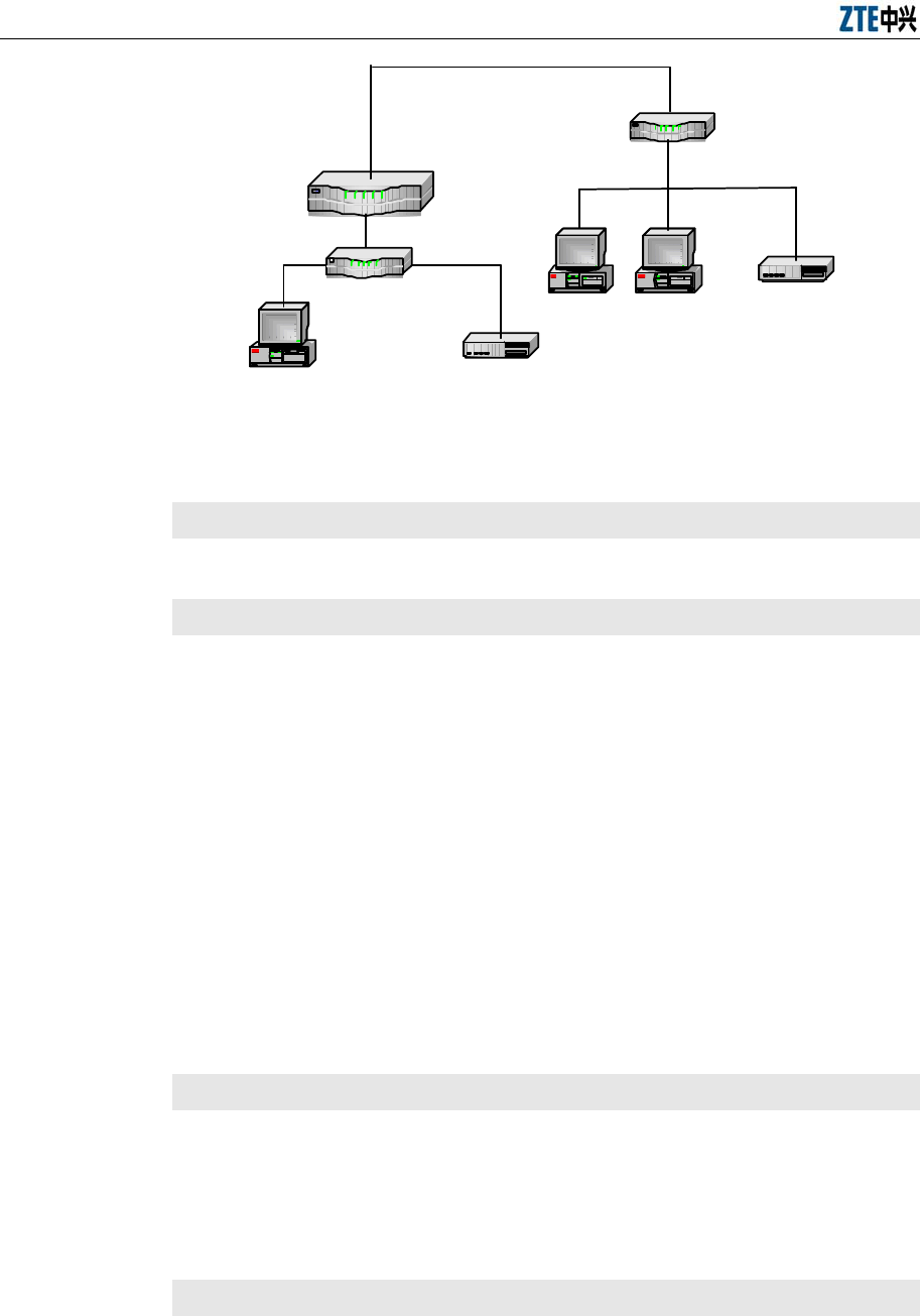
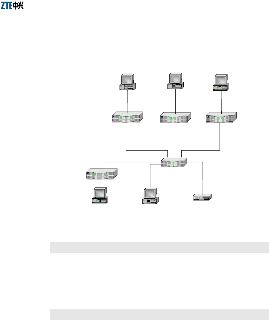
6.3 Multi-Office-in-One Networking
Purpose
Multi-office-in-one means that up to 10 groups of alarm servers can be
connected to an alarm box. The alarm servers may be located in different
network segments. Therefore, remote deployment should be employed in the
multi-office-in-one networking.
Chapter 6 Alarm Box Networking
6-7
Assume that five alarm servers are connected to the alarm box. Only one of
the servers resides in the network segment 192.168.60.* where the alarm box
is located, as shown in Figure 6.3-1.
R o u t e
r
Server-2 alarmpro
Server-1
…
193.1.2.129
F0/1
193.1.2.100
F0/0
192.168.60.100
192.168.60.254
HUB
R o u t e r
192.168.60.129
Server-4
195.1.2.129
F0/0
195.1.2.100
F0/1
192.168.60.102
R o u t e r
Server-3
194.1.2.129
F0/0
194.1.2.100
F0/1
192.168.60.101
R o u t e r
Server-5
196.1.2.129
F0/0
196.1.2.100
F0/1
192.168.60.103
Figure 6.3-1 Multi-Office-in-One Networking Diagram
Prerequisites
TCP port 5000 is already configured on each of the alarm servers.
The IP address of the PC connected to the alarm box is already
configured.
You have telneted the local alarm box from the PC. For details, see 5.2.
Steps
1. Configure the IP address, port number, and group ID of each alarm
server.
601>cfgTcpComm 1 192.168.60.129 5000 1
601>cfgTcpComm 1 193.1.2.129 5000 2
601>cfgTcpComm 2 194.1.2.129 5000 3

Alarm Box User Manual
6-8
601>cfgTcpComm 3 195.1.2.129 5000 4
601>cfgTcpComm 4 196.1.2.129 5000 5
Note:
If the alarm box interacts with alarm servers through UDP, run the
cfgUdpComm command to configure the UDP connection. For details, see
5.4.1.6.
2. View the configurations of the alarm servers.
601>tcpCfgShow
************************************************************
LocalIp = 192.168.60.254 (IP address of the alarm box)
LocalMask = 255.255.255.0 (Subnet mask of the alarm box)
***********Sequence 1 :****************
Port1 = 5000
ServerIp1 = 192.168.60.129
GroupId1 = 1
link1 state: Active (The alarm box is connected to
the first alarm box)
***********Sequence2 :****************
Port2 = 5000
ServerIp2 = 193.1.2.129
GroupId2 = 2
link2 state: Break (The alarm box cannot interact with the
second alarm server as the route to the server is not configured yet)
***********Sequence 3 :****************
Port3 = 5000
ServerIp3 = 194.1.2.129

Chapter 6 Alarm Box Networking
6-9
GroupId3 = 3
link3 state: Break
***********Sequence 4 :****************
Port4 = 5000
ServerIp4 = 195.1.2.129
GroupId4 = 4
link4 state: Break
***********Sequence 5 :****************
Port5 = 5000
ServerIp5 = 196.1.2.129
GroupId5 = 5
link5 state: Break
************************************************************
3. Configure the routing information for the second to fifth servers.
601>routeSave 193.1.2.129 192.168.60.100
601>routeSave 194.1.2.129 192.168.60.101
601>routeSave 195.1.2.129 192.168.60.102
601>routeSave 196.1.2.129 192.168.60.103
4. Check if the routing information is saved successfully in the flash.
601>routeFlashShow
***sequence.******destination**********gateway************
1 193.1.2.129 192.168.60.100
2 194.1.2.129 192.168.60.101
3 195.1.2.129 192.168.60.102
4 196.1.2.129 192.168.60.103
**********************************************************

Alarm Box User Manual
6-10
5. Restart the alarm box. The routing information takes effect.
6. Telnet the alarm box from the alarm server, and then run the ping
command to check the connectivity between the alarm box and the
server.
6.4 Cross-VLAN Networking
Purpose
The alarm box can interact with alarm servers in different VLANs through a
layer-2 switch, isolating the servers from each other.
Assume that the following three alarm servers are connected to the alarm box:
Server 192.168.1.1
Server 10.44.40.7
Server 126.11.152.6
Moreover, the local IP of the alarm box is configured to 10.44.40.254 and the
alarm box is connected to the trunk interface of the layer-2 switch, as shown in
Figure 6.4-1.
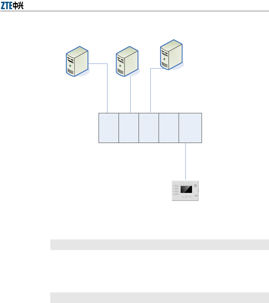
Chapter 6 Alarm Box Networking
6-11
VLAN1 VLAN2 VLAN3 ... TRUNKLayer-2 Switch
OMC1
(192.168.1.1)
OMC2
(10.44.40.7)
OMC3
(126.11.152.254)
Alarm Box
(10.44.40.254)
VLAN tags are
removed when
packets go through
the ports to alarm
servers
Trunk interface belonging to
multiple VLANs
Packets going through it to
alarm box are labeled with
VLAN tags
Figure 6.4-1 Cross-VLAN Networking Diagram
Prerequisites
The IP address of the PC connected to the alarm box is already
configured.
You have telneted the alarm box from the PC. For details, see 5.2.
Steps
1. Perform the VLAN configurations on the alarm box: Configure the VLAN
ID of each alarm server.
601> VlanCfgAdd 192.168.1.1 1
vlancfg add success!
601> VlanCfgAdd 10.44.40.7 2
vlancfg add success!

Alarm Box User Manual
6-12
601> VlanCfgAdd 126.11.152.254 3
vlancfg add success!
601>VlanCfgShow
***sequence.*******IpAddress***********VlanId**********
1 192.168.1.1 1
2 10.44.40.7 2
3 126.11.152.254 3
*****************************************************
2. Configure the IP address of the alarm box. As OMC1, OMC3, and the
alarm box reside in different network segments, you need to configure
two IP addresses for the alarm box so that the alarm box can interact
with the two servers. Configure the IP addresses to 192.168.1.254 and
10.44.40.253 respectively.
601>MultiIpCfgAdd 126.11.152.253
IpAddr add success!
601>MultiIpCfgAdd 192.168.1.254
IpAddr add success!
601>MultiIpCfgShow
***sequence.******IpAddr**********NetMask************
1 126.11.152.253 255.255.0.0
2 192.168.1.254 255.255.0.0
****************************************************
601>routeshow
ROUTE NET TABLE
destination gateway flags Refcnt Use
Interface
----------------------------------------------------------------------------
10.40.0.0 40.120.254 101 0 0 cpm0

Chapter 6 Alarm Box Networking
6-13
126.11.0.0 126.11.152.253 101 0 0 cpm0
192.168.0.0 192.168.1.254 101 0 0 cpm0
----------------------------------------------------------------------------
ROUTE HOST TABLE
destination gateway flags Refcnt Use
Interface
----------------------------------------------------------------------------
10.44.120.2 23.3.3.3 7 0 0 cpm0
127.0.0.1 127.0.0.1 5 1 0 lo0
----------------------------------------------------------------------------
3. Modify the subnet mask on the LCD screen of the alarm box. Ensure the
subnet mask can support communications between the alarm box and
each of the alarm servers. In this example, configure the subnet mask to
255.255.255.0.
4. Run the cfgTcpComm or cfgUdpComm command to set up a TCP or
UDP connection between the alarm box and each alarm server. Assign
different group IDs to the alarm servers.
5. Restart the alarm box.
6. Perform necessary configurations on the alarm servers and connect
them to the alarm box. The networking configuration is complete.
A-1
Appendix A Alarm Box Upgrade
A.1 Introduction
Description
This chapter describes how to upgrade the alarm box, including fonts, alarm
sound (voice), the boot program and the version program.
Contents
Topic Section
Setting FTP A-1
Loading Version Files A-3
A.2 Setting FTP Parameters
Purpose
The version files are transferred from the server to the flash disk of the alarm
box through FTP. These files are loaded to the RAM before they are run.
Therefore, FTP parameters must be set correctly.
Prerequisites
The path of the version files is known.
An operation and maintenance console is deployed as the FTP server
where the version files of the alarm box are stored.
Steps
1. On the FTP server, run the WFTPD.exe file. Select Security >
User/rights.
2. Click New User…. The new user dialog box appears.
3. Enter the user name zxwb and click OK.
4. In the pop-up dialog box, enter the password zxwb and click OK.
5. Enter the directory that stores the version files to be downloaded.
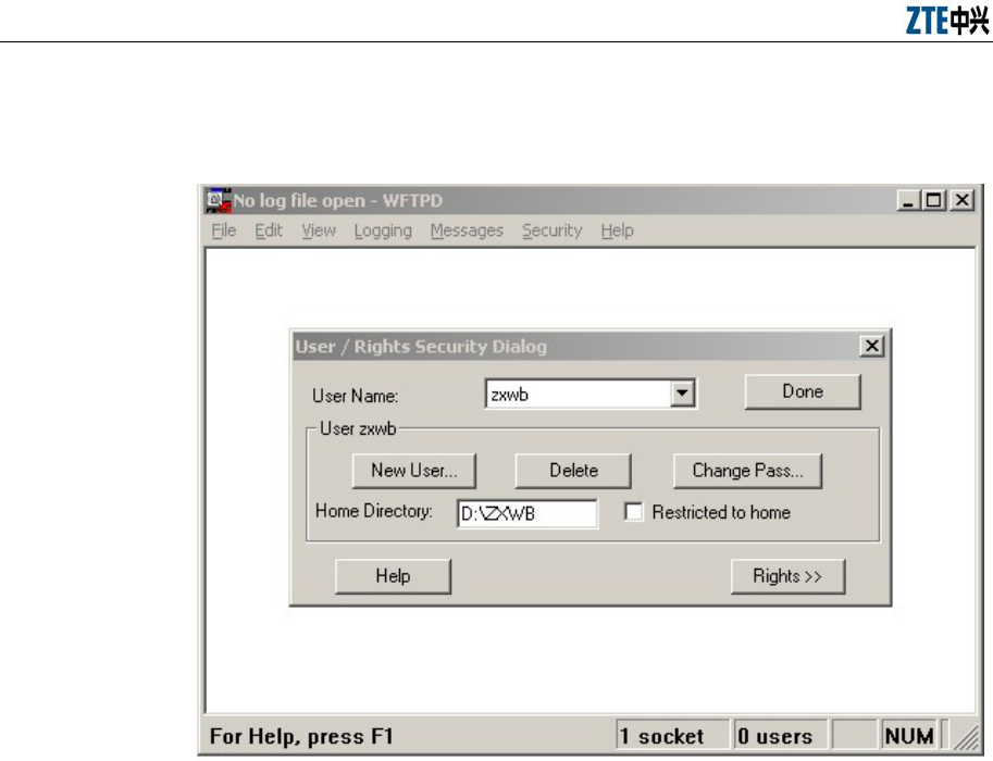
Alarm Box User Manual
A-2
For example, the D:\ZXWB directory includes the font file, the version
program, the boot program, and the voice file, as shown in Figure A.2-1.
Figure A.2-1 Setting the Path of Files to Be Downloaded
6. Click Done to complete the settings of the new user and file path.
7. Select Logging > logging Options, and then select all the options, as
shown in Figure A.2-2. The download status can be displayed during the
download process.
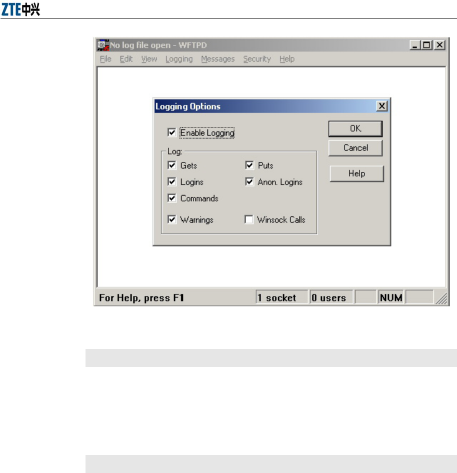
Appendix A Alarm Box Upgrade
A-3
Figure A.2-2 Setting the Log Options
Follow-Up
You need to set the HyperTerminal and load the version files. For details, see
A.3.
A.3 Loading Version Files
Purpose
The version files include the LCD display font file, the alarm sound (voice) file,
the boot program, and the version program. You can download these version
files by using the HyperTerminal through FTP. The download process is divided
into the following:
1. Configure the HyperTerminal (Step 1 - 5).
2. Create the flash file system in the alarm box (Step 6).
3. Set the network parameters (Step 7 - 10).
4. Download the boot program, font file, alarm sound file, and version
program (Step 11 - 17).
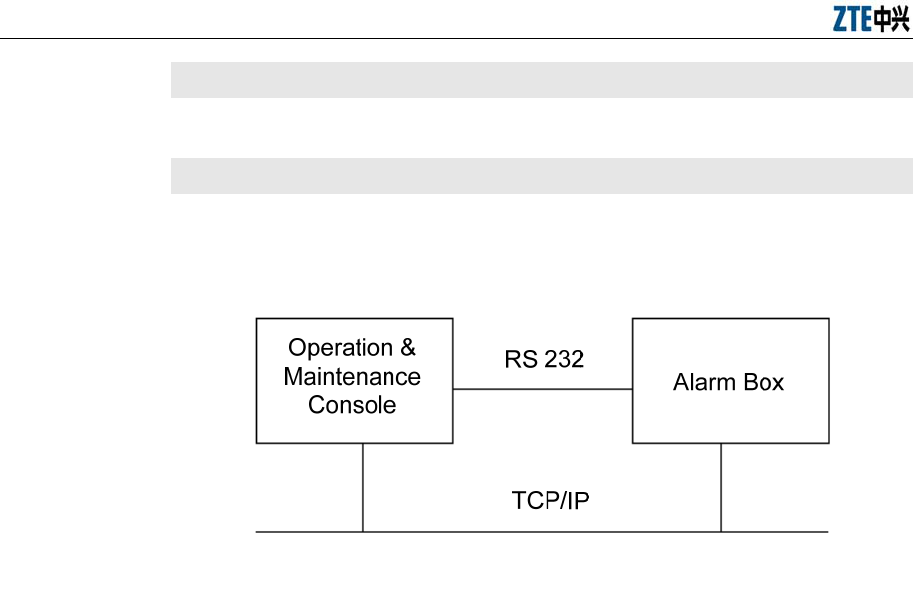
Alarm Box User Manual
A-4
Prerequisites
The version files should be copied to the specified FTP directory.
Steps
1. The operation and maintenance console is connected to the alarm box
using a RS232 serial cable through the LAN, as shown in Figure A.3-1.
Figure A.3-1 Hardware Connection
2. Start the HyperTerminal and select the available port COM1.
3. Set the properties of COM1, as shown in Figure A.3-2.
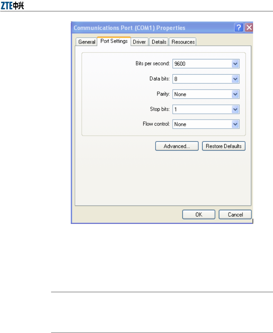
Appendix A Alarm Box Upgrade
A-5
Figure A.3-2 Setting the Port Properties
4. Start the alarm box and run the HyperTerminal. When the system counts
down the seconds (3 seconds), press any key. The system displays the
Boot Password(3GPLAT or 3gplat)-> prompt.
Note:
If you do not press any key in three seconds, the system automatically loads
the version saved in the flash.
5. At this prompt, enter the password 3gplat or 3GPLAT. The BSP menu
appears, as shown in Figure A.3-3. Enter ? if you need help.
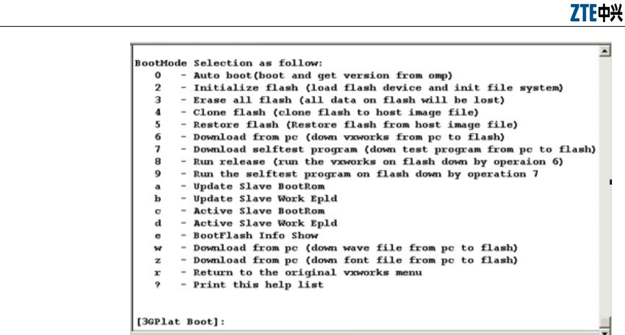
Alarm Box User Manual
A-6
Figure A.3-3 HyperTerminal Interface
6. If the software version of the alarm box is upgraded from a lower version
to V5.0, you need to format the flash to create a file system.
1) Enter 3 to erase the files saved in the flash.
2) Enter 2 to initialize the flash.
7. At the 3GPlat Boot prompt, enter r and press Enter. The system
displays the Vxworks Boot prompt, as shown in Figure A.3-4.
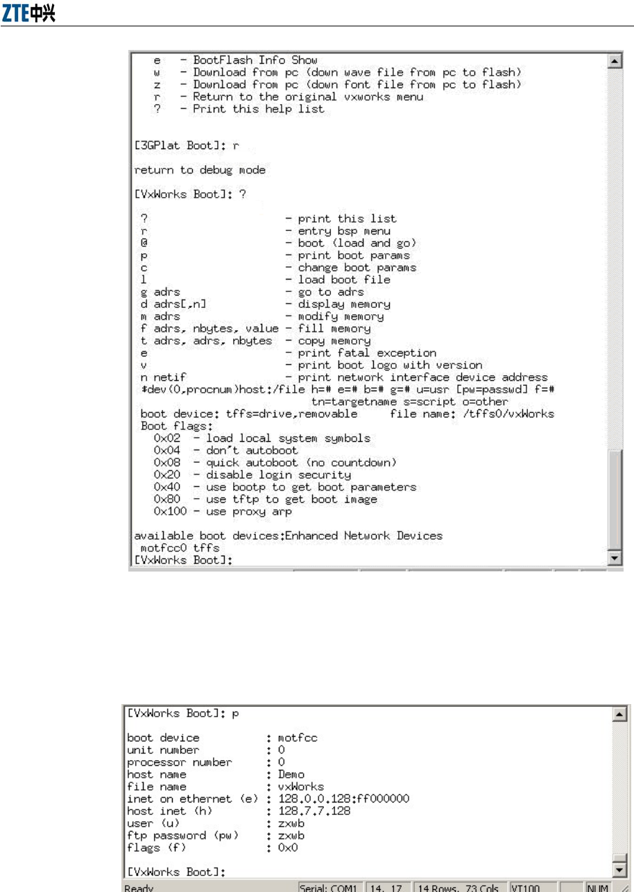
Appendix A Alarm Box Upgrade
A-7
Figure A.3-4 Vxworks Menu
8. At the VxWorks Boot prompt, enter p to display the current network
parameter settings, as shown in Figure A.3-5.
Figure A.3-5 Network Parameter Settings
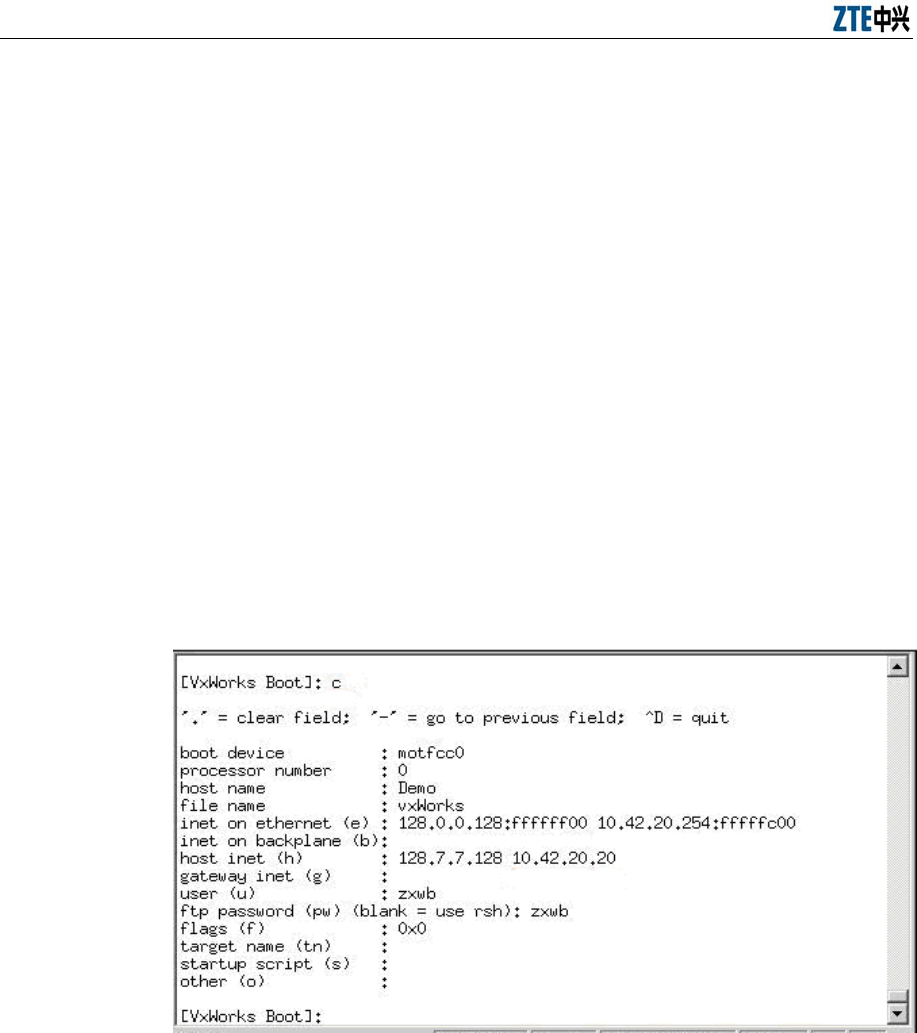
Alarm Box User Manual
A-8
9. Enter c and press Enter. Modify the parameters.
boot device: Indicates the network interface name. Set it to motfcc0.
Filename: Indicates the name of the image file. The name should be the
same with the name of the version program, namely vxWorks.
inet on ethernet (e): Indicates the IP address of the alarm box, for
example 10.42.20.254.
host inet (h): Indicates the IP address of the PC where the version file is
stored, for example 10.42.20.20.
user (u): Indicates the FTP user name that should be the same with that
on the FTP server. By default, the FTP user name is zxwb.
ftp password (pw): Indicates the FTP password that should be the
same with that on the FTP server. By default, the FTP password is zxwb.
Press Enter to ignore other parameters, as shown in Figure A.3-6.
Figure A.3-6 Setting the Network Parameters
10. Enter r and press Enter to return to the BSP menu.
11. At the 3GPlat Boot prompt, enter a and press Enter to download the
boot program, as shown in Figure A.3-7.
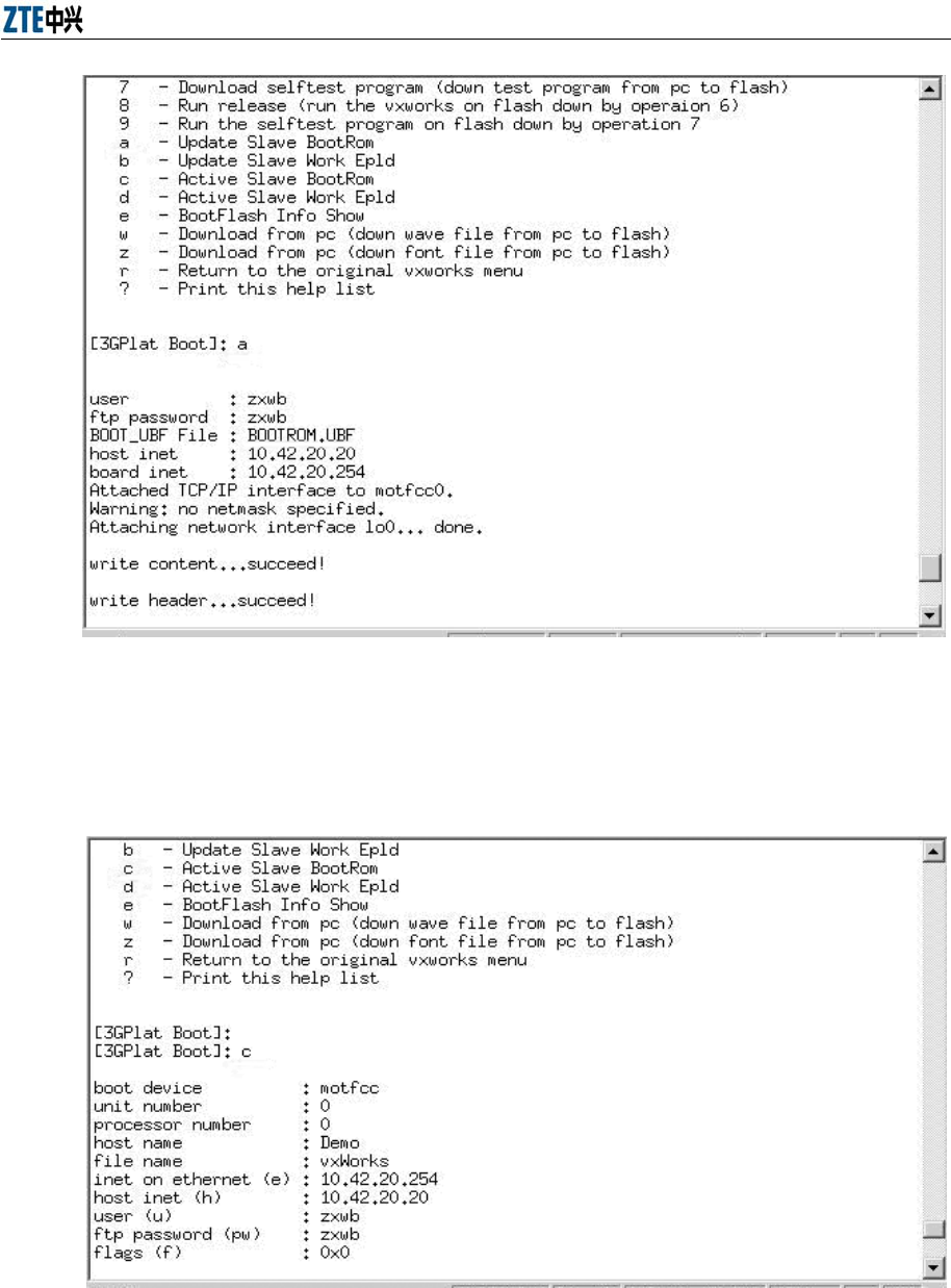
Appendix A Alarm Box Upgrade
A-9
Figure A.3-7 Downloading the Boot Program
12. After the boot program is downloaded successfully, enter c and press
Enter to activate the boot program, as shown in Figure A.3-8.
Figure A.3-8 Activating the Boot Program
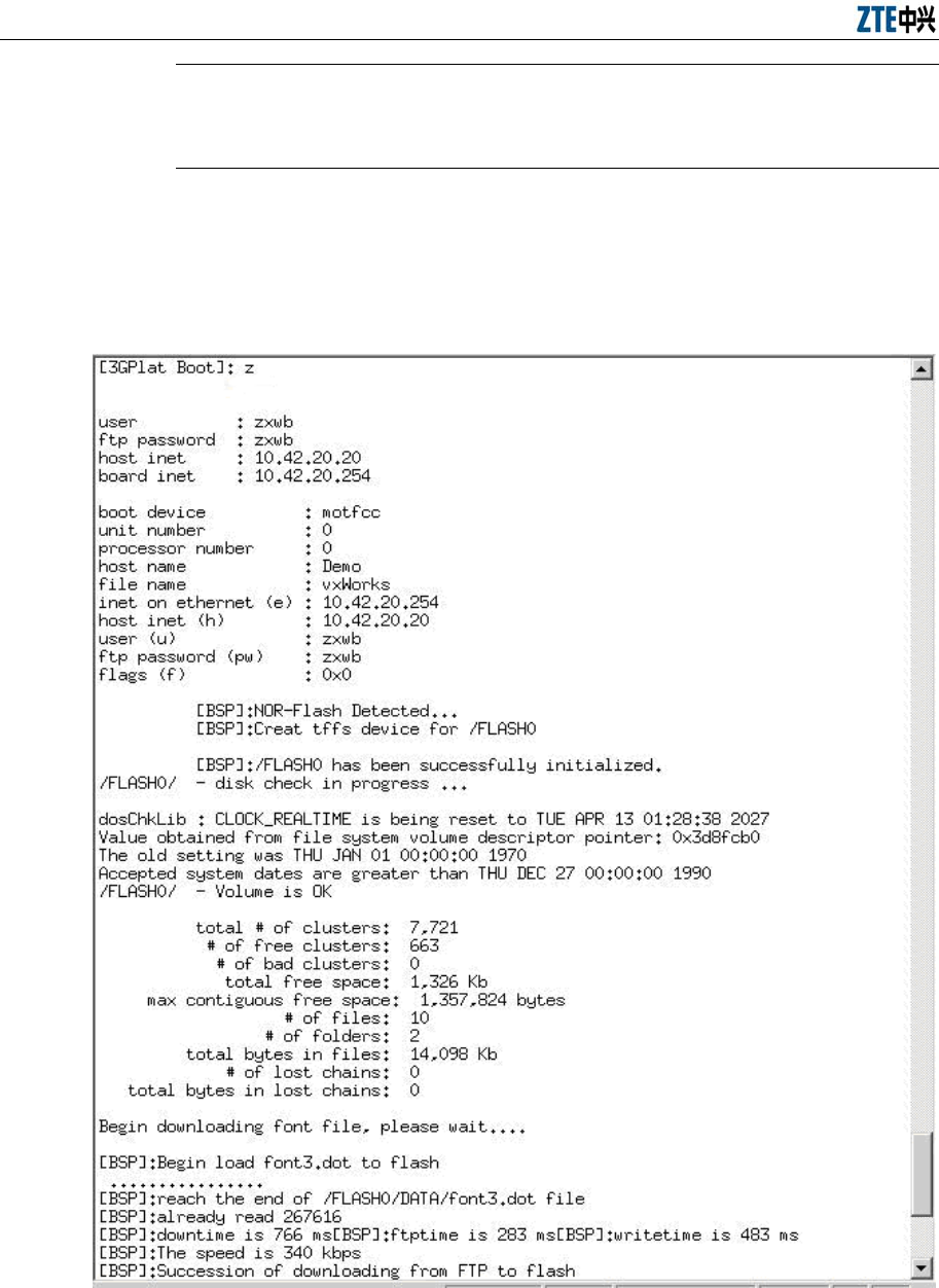
Alarm Box User Manual
A-10
Note:
The boot program can be run only after you restart the alarm box.
13. At the 3GPlat Boot prompt, enter z and press Enter to download the
font file. After successful download, the system returns to the BSP menu,
as shown in Figure A.3-9.
Figure A.3-9 Downloading the Font File
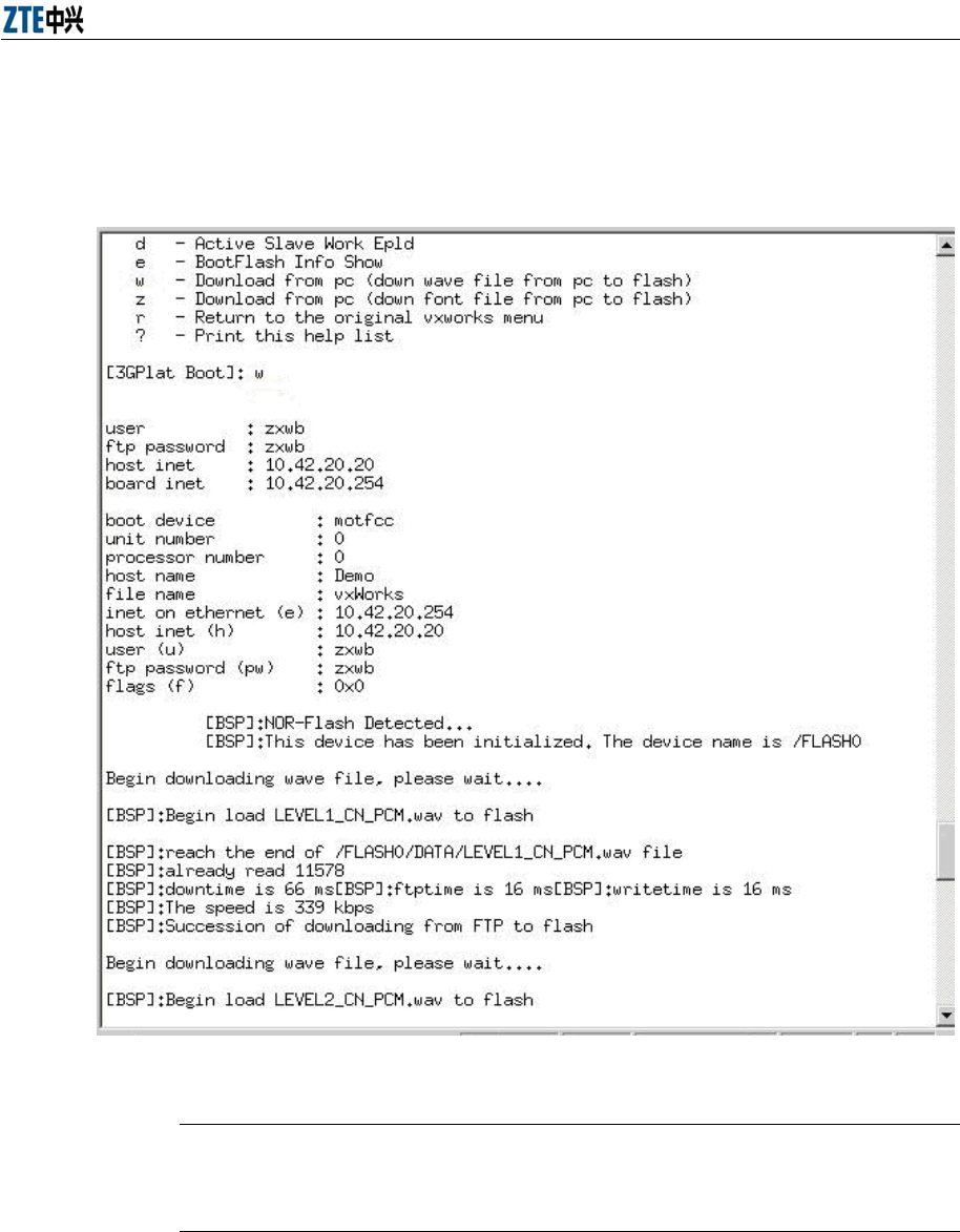
Appendix A Alarm Box Upgrade
A-11
14. At the 3GPlat Boot prompt, enter w and press Enter to download the
alarm sound file. After successful download, the system returns to the
BSP menu, as shown in Figure A.3-10.
Figure A.3-10 Downloading the Alarm Sound File
Note:
Generally, the font file and the alarm sound file do not need to be upgraded.
15. At the 3GPlat Boot prompt, enter 6 and press Enter to download the
version program. After successful download, the system returns to the
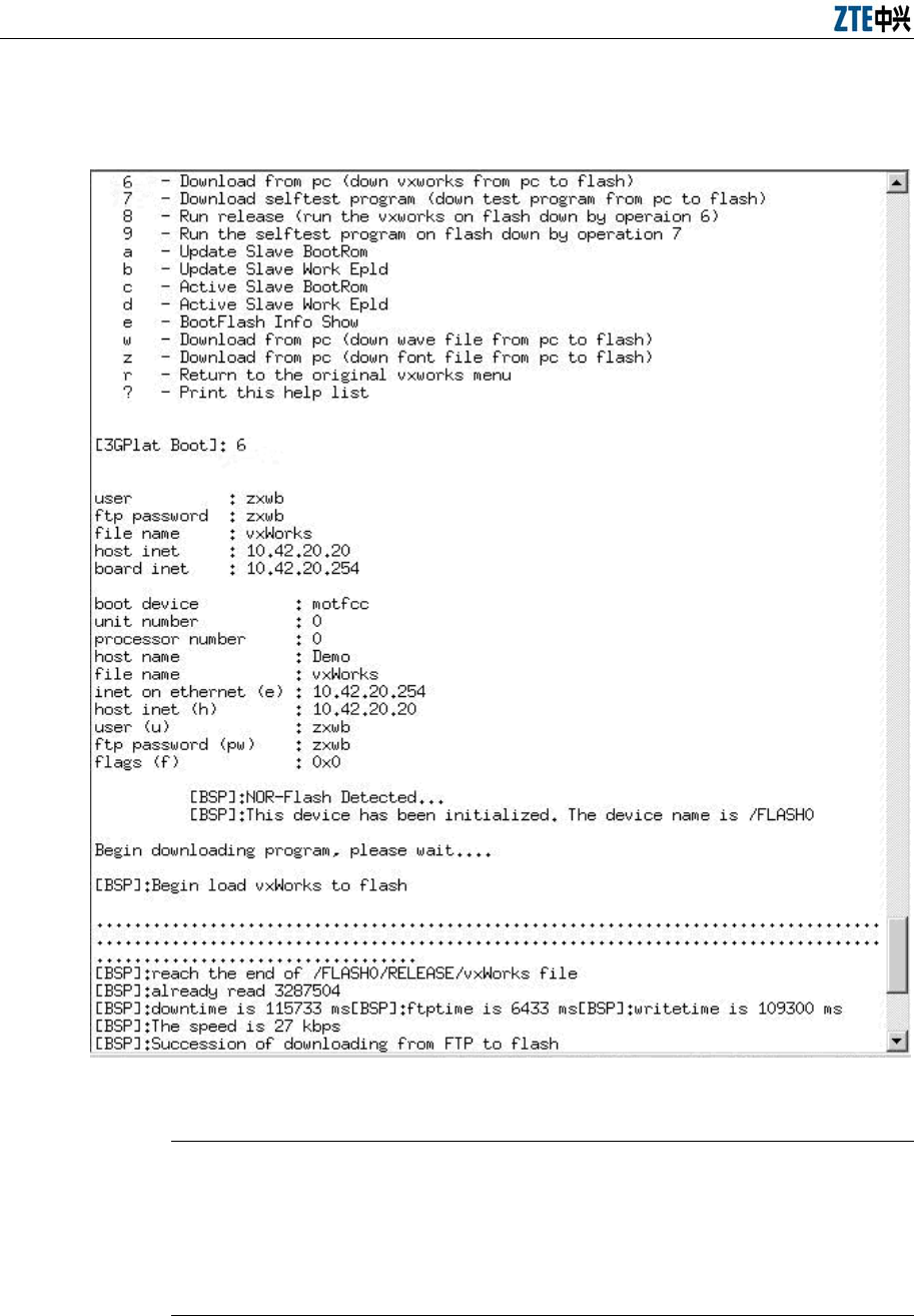
Alarm Box User Manual
A-12
BSP menu (maybe you need to wait three to five minutes), as shown in
Figure A.3-11.
Figure A.3-11 Downloading the Version Program
Note:
It may take you a long period of time to download the version program. If any
error occurs during the download process, you need to restart the alarm box
and then download the version program again.
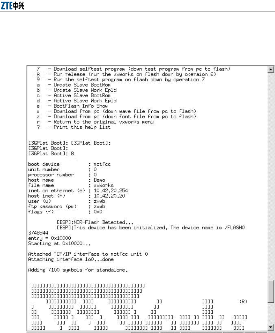
Appendix A Alarm Box Upgrade
A-13
16. At the 3GPlat Boot prompt, enter 0 and press Enter to automatically
start the new version from the flash. Otherwise, you can enter 8 and
press Enter to run the new version, as shown in Figure A.3-12.
Figure A.3-12 Running the New Version
17. After the upgrade, press ◄ on the alarm box panel to view the current
version.

Alarm Box User Manual
A-14
Caution:
Assume that the boot program is already upgraded to v5.0. If you need to
upgrade any one of boot, version, sound, and font, you do not need to format
the flash. You can refer to the preceding steps related to the file that you need
to download. The downloaded file overwrites the old one in the flash.
RF exposure information: To maintain compliance with FCC RF exposure
requirements, use handset that maintain a 20cm separation distance between the user's
body and the host.
MPE limit for RF exposure at prediction frequency is 0.558mW/cm2 for GSM850MHz
and 1mW/cm2 for GSM1900MHz. The MPE for GSM850MHz is 0.46 mW/cm2 and
0.421mW/cm2 for GSM1900MHz. It satisfy RF exposure compliance.
This device complies with part 15 of the FCC rules. Operation is subject to the
following two conditions: (1) this device may not cause harmful interference, and (2)
this device must accept any interference received, including interference that may
cause undesired operation.

B-1
Appendix B Acronyms and Abbreviations
Abbreviation Full Name
APN Access Point Name
DNS Domain Name Server
FTP File Transfer Protocol
GPRS General Packet Radio Service
ISP Internal Service Provider
MAC Media Access Control
OMC Operation Maintenance Center
TCP/IP Transmission Control Protocol/Internet Protocol