ZTE C196 CDMA Remote Radio Unit User Manual
ZTE Corporation CDMA Remote Radio Unit
UserManual.wiki
>
ZTE
>
C196 User Manual
User Manual
Navigation menu
Upload a User Manual
Namespaces
Wiki Guide
HTML
PDF
Info
Views
User Manual
Discussion / Help
Navigation

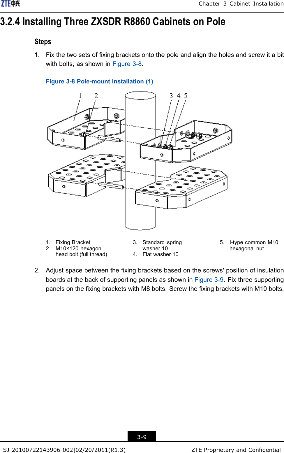
![FCC&ICSTATEMENTThisdevicecomplieswithpart15oftheFCCRules.Operationissubjecttothefollowingtwoconditions:1.Thisdevicemaynotcauseharmfulinterference.2.Thisdevicemustacceptanyinterferencereceived,includinginterferencethatmaycauseundesiredoperation.ThisClass[A]digitalapparatuscomplieswithCanadianICES-003.Note:Workingwiththeequipmentwhileinoperation,mayexposethetechniciantoRFelectromagneticeldsthatexceedFCCrulesforhumanexposure.VisittheFCCwebsiteatwww.fcc.gov/oet/rfsafetytolearnmoreabouttheeffectsofexposuretoRFelectromagneticelds.Changesormodicationstothisunitnotexpresslyapprovedbythepartyresponsibleforcompliancewillvoidtheuser’sauthoritytooperatetheequipment.AnychangetotheequipmentwillvoidFCCandICgrant.ThisequipmenthasbeentestedandfoundtocomplywiththelimitsforaClassAdigitaldevice,pursuanttotheFCCandICRules.Thisequipmentgenerates,usesandcanradiateradiofrequencyenergyand,ifnotinstalledandusedinaccordancewiththeinstructions,maycauseharmfulinterferencetoradiocommunications.However,thereisnoguaranteethatinterferencewillnotoccurinaparticularinstallation.I](https://usermanual.wiki/ZTE/C196/User-Guide-1506221-Page-5.png)