User Manual

ZXSDRR8860
CDMARemoteRadioUnit-8860
InstallationManual
ZTECORPORATION
NO.55,Hi-techRoadSouth,ShenZhen,P .R.China
Postcode:518057
Tel:+86-755-26771900
Fax:+86-755-26770801
URL:http://ensupport.zte.com.cn
E-mail:support@zte.com.cn

LEGALINFORMATION
Copyright©2011ZTECORPORATION.
Thecontentsofthisdocumentareprotectedbycopyrightlawsandinternationaltreaties.Anyreproductionor
distributionofthisdocumentoranyportionofthisdocument,inanyformbyanymeans,withoutthepriorwritten
consentofZTECORPORATIONisprohibited.Additionally,thecontentsofthisdocumentareprotectedby
contractualcondentialityobligations.
Allcompany,brandandproductnamesaretradeorservicemarks,orregisteredtradeorservicemarks,ofZTE
CORPORATIONoroftheirrespectiveowners.
Thisdocumentisprovided“asis”,andallexpress,implied,orstatutorywarranties,representationsorconditions
aredisclaimed,includingwithoutlimitationanyimpliedwarrantyofmerchantability,tnessforaparticularpurpose,
titleornon-infringement.ZTECORPORATIONanditslicensorsshallnotbeliablefordamagesresultingfromthe
useoforrelianceontheinformationcontainedherein.
ZTECORPORATIONoritslicensorsmayhavecurrentorpendingintellectualpropertyrightsorapplications
coveringthesubjectmatterofthisdocument.ExceptasexpresslyprovidedinanywrittenlicensebetweenZTE
CORPORATIONanditslicensee,theuserofthisdocumentshallnotacquireanylicensetothesubjectmatter
herein.
ZTECORPORATIONreservestherighttoupgradeormaketechnicalchangetothisproductwithoutfurthernotice.
UsersmayvisitZTEtechnicalsupportwebsitehttp://ensupport.zte.com.cntoinquirerelatedinformation.
TheultimaterighttointerpretthisproductresidesinZTECORPORATION.
RevisionHistory
RevisionNo.RevisionDateRevisionReason
R1.008/30/2010FirstEdition
R1.112/30/2010ModifyStylesheetDropthecontentofinstallingWaveTrapDrop
thecontentofinstallingSunshield
R1.201/20/2011Waterproofprocessingmustbeperformedonalltheoutdoor
metalconnectorsoftheRRUs.
R1.302/20/2011AddinstallingPIMDCDroptheFloorStand-mountedInstallation
ModeDroptheSimpliedCabinetIntegratedInstallationMode
SerialNumber:SJ-20100722143906-002
PublishingDate:02/20/2011(R1.3)

DeclarationofRoHS
Compliance
Tominimizetheenvironmentalimpactandtakemoreresponsibilitytotheearthwelive,
thisdocumentshallserveasformaldeclarationthatZXSDRR8860manufacturedby
ZTECORPORATIONareincompliancewiththeDirective2002/95/ECoftheEuropean
Parliament-RoHS(RestrictionofHazardousSubstances)withrespecttothefollowing
substances:
lLead(Pb)
lMercury(Hg)
lCadmium(Cd)
lHexavalentChromium(Cr(VI))
lPolyBrominatedBiphenyls(PBB’s)
lPolyBrominatedDiphenylEthers(PBDE’s)
…
TheZXSDRR8860manufacturedbyZTECORPORATIONmeettherequirementsofEU2002/95/EC;
however,someassembliesarecustomizedtoclientspecications.Additionofspecialized,
customer-speciedmaterialsorprocesseswhichdonotmeettherequirementsofEU2002/95/EC
maynegateRoHScomplianceoftheassembly.T oguaranteecomplianceoftheassembly,the
needforcompliantproductmustbecommunicatedtoZTECORPORATIONinwrittenform.This
declarationisissuedbasedonourcurrentlevelofknowledge.Sinceconditionsofuseareoutside
ourcontrol,ZTECORPORATIONmakesnowarranties,expressorimplied,andassumesnoliability
inconnectionwiththeuseofthisinformation.
I

II

FCC&ICSTATEMENT
Thisdevicecomplieswithpart15oftheFCCRules.Operationissubjecttothefollowing
twoconditions:
1.Thisdevicemaynotcauseharmfulinterference.
2.Thisdevicemustacceptanyinterferencereceived,includinginterferencethatmay
causeundesiredoperation.
ThisClass[A]digitalapparatuscomplieswithCanadianICES-003.
Note:
Workingwiththeequipmentwhileinoperation,mayexposethetechniciantoRF
electromagneticeldsthatexceedFCCrulesforhumanexposure.VisittheFCC
websiteatwww.fcc.gov/oet/rfsafetytolearnmoreabouttheeffectsofexposuretoRF
electromagneticelds.
Changesormodicationstothisunitnotexpresslyapprovedbythepartyresponsiblefor
compliancewillvoidtheuser’sauthoritytooperatetheequipment.Anychangetothe
equipmentwillvoidFCCandICgrant.
ThisequipmenthasbeentestedandfoundtocomplywiththelimitsforaClassAdigital
device,pursuanttotheFCCandICRules.Thisequipmentgenerates,usesandcan
radiateradiofrequencyenergyand,ifnotinstalledandusedinaccordancewiththe
instructions,maycauseharmfulinterferencetoradiocommunications.However,thereis
noguaranteethatinterferencewillnotoccurinaparticularinstallation.
I

II

RFExposureInformationfor
PMR
TheproductgeneratesRFelectromagneticenergyduringtransmitmode.
Thisradioisdesignedforandclassiedas“OccupationalUseOnly”,meaningitmust
beusedonlyduringthecourseofemploymentbyindividualsawareofthehazards,and
thewaystominimizesuchhazards.ThisradioisNOTintendedforusebythe“General
Population”inanuncontrolledenvironment.
ThisradiohasbeentestedandcomplieswiththeFCCRFexposurelimitsfor“Occupational
UseOnly”.
Inaddition,theproductcomplieswiththefollowingStandardsandGuidelineswithregard
toRFenergyandelectromagneticenergylevelsandevaluationofsuchlevelsforexposure
tohumans:
1.FCCOETBulletin65Edition97-01SupplementC,EvaluatingCompliancewithFCC
GuidelinesforHumanExposuretoRadioFrequencyElectromagneticFields.
2.tAmericanNationalStandardsInstitute(C95.1-1992),IEEEStandardforSafetyLevels
withRespecttoHumanExposuretoRadioFrequencyElectromagneticFields,3kHz
to300GHz.
3.AmericanNationalStandardsInstitute(C95.3-1992),IEEERecommendedPractice
fortheMeasurementofPotentiallyHazardousElectromagneticFields–RFand
Microwave.
4.Thefollowingaccessoriesareauthorizedforusewiththisproduct.Useofaccessories
otherthanthose(listedintheinstruction)speciedmayresultinRFexposurelevels
exceedingtheFCCrequirementsforwirelessRFexposure.
I

II

AboutThisManual
Purpose
ZXSDRR8860isanoutdoorremoteRFunit.ComposinganintegratedBTS,ZXSDR
R8860andZXSDRR8860implementwirelesstransmissionwithincoverageareas,control
ofwirelesschannelaswellascommunicationwithBSC.
Thismanualprovidesbasicinstallationguideforengineeringpersonnelwhoperform
ZXSDRR8860hardwareinstallation.Atthesametime,itservesforthereference
materialforthepersonnelresponsibleforoperationandmaintenance.
IntendedAudience
Thisdocumentisintendedforengineersandtechnicianswhoperformoperationactivities
ZXSDRR8860.
lEngineeringtechnicians
lEquipmentinstallationengineers
lEquipmentcommissioningengineers
PrerequisiteSkillandKnowledge
Tousethisdocumenteffectively,usersshouldhaveageneralunderstandingofZXSDR
R8860equipmentanditscomponents.Familiaritywiththefollowingishelpful:
lZXSDRR8860hardwarestructure
lBasicsoftwareknowledge
WhatisinThisManual
Thismanualcontainsthefollowingchapters:
ChapterSummary
Chapter1SafetyDescriptionDescribessafetyprecautionsduringZXSDRR8860installation
oroperationmaintenanceaswellasmeaningsofvarioussafety
symbols.
Chapter2Installation
Overview
DescribestheZXSDRR8860installationowsandinstallation
precautions.
Chapter3CabinetInstallationDescribesfourinstallationmodesofZXSDRR8860cabinetand
installationsituations.
Chapter4ExternalCable
Installation
DescribestheinstallationmethodsofvariousZXSDRR8860external
cables.
Chapter5MainAntenna
FeederSystemInstallation
DescribestheinstallationowsandinstallationmethodsofZXSDR
R8860mainantennafeedersystem.
I

ChapterSummary
Chapter6Hardware
InstallationInspection
Describestheinspectionmethodsofcabinetandcablesafter
installationcompletion.
Chapter7PoweronandoffDescribesthemethodsandprecautionsofZXSDRR8860power
onandoff.
Conventions
ZTEdocumentsemploythefollowingtypographicalconventions.
TypefaceMeaning
ItalicsReferencestootherManualsanddocuments.
“Quotes”Linksonscreens.
BoldMenus,menuoptions,functionnames,inputelds,radiobuttonnames,check
boxes,drop-downlists,dialogboxnames,windownames.
CAPSKeysonthekeyboardandbuttonsonscreensandcompanyname.
Note:Providesadditionalinformationaboutacertaintopic.
Checkpoint:Indicatesthataparticularstepneedstobecheckedbefore
proceedingfurther.
Tip:Indicatesasuggestionorhinttomakethingseasierormoreproductive
forthereader.
Mouseoperationconventionsarelistedasfollows:
TypefaceMeaning
ClickReferstoclickingtheprimarymousebutton(usuallytheleftmousebutton)once.
Double-clickReferstoquicklyclickingtheprimarymousebutton(usuallytheleftmousebutton)
twice.
Right-clickReferstoclickingthesecondarymousebutton(usuallytherightmousebutton)
once.
II

Contents
DeclarationofRoHSCompliance.................................................................I
FCC&ICSTATEMENT...................................................................................I
RFExposureInformationforPMR................................................................I
AboutThisManual.........................................................................................I
Chapter1SafetyDescription....................................................................1-1
1.1SafetySpecicationsGuide................................................................................1-1
1.2SafetySymbols..................................................................................................1-2
1.3SafetyInstructions..............................................................................................1-3
Chapter2InstallationOverview................................................................2-1
2.1ComponentstobeInstalled.................................................................................2-1
2.2InstallationFlow.................................................................................................2-1
2.3InstallationPreparation.......................................................................................2-2
2.3.1EngineeringConditionInspection..............................................................2-2
2.3.2T oolsandInstrumentsPreparation............................................................2-4
2.3.3On-siteDocuments..................................................................................2-9
2.3.4UnpackingAcceptance...........................................................................2-10
Chapter3CabinetInstallation...................................................................3-1
3.1EngineeringIndices............................................................................................3-1
3.2Pole-mountedInstallationMode..........................................................................3-2
3.2.1ComponentsUsedinPole-mountInstallation.............................................3-2
3.2.2InstallingSingleCabinetonPole(Pole–Mount).........................................3-5
3.2.3InstallingTwoZXSDRR8860Pole-mountCabinets....................................3-6
3.2.4InstallingThreeZXSDRR8860CabinetsonPole.......................................3-9
3.3Wall-mountedInstallationMode..........................................................................3-11
3.3.1ComponentsUsedinWall-MountInstallation............................................3-11
3.3.2InstallingCabinetonWall(Wall-Mount)....................................................3-12
Chapter4ExternalCableInstallation.......................................................4-1
4.1ExternalCableLayout........................................................................................4-1
4.2ExternalCableInstallationFlow..........................................................................4-2
4.3Specicationsof1+3+3WaterproofProcessingwithPlasterandTape...................4-4
4.4InstallingPowerCable........................................................................................4-6
4.5InstallingGroundingCable..................................................................................4-7
I

4.6InstallingFiberbetweenBBUandRRU................................................................4-9
4.7InstallingFiberbetweenRRUandRRU.............................................................4-10
4.8InstallingEnvironmentMonitoringCable............................................................4-12
4.9InstallingAISGControlCable............................................................................4-13
4.10InstallingFrequencyPointExtensionCable......................................................4-14
4.11InstallingJumper............................................................................................4-15
4.12InstallingPIMDC............................................................................................4-16
4.12.1PIMDCechnicalIndices........................................................................4-16
4.12.2PIMDCAppearance..............................................................................4-17
4.12.3PIMDCInstallationDescription..............................................................4-18
Chapter5MainAntennaFeederSystemInstallation..............................5-1
5.1MainAntennaFeederSystemStructure...............................................................5-1
5.2MainAntennaFeederSystemInstallationPreparation..........................................5-7
5.3MainAntennaFeederSystemInstallationFlow....................................................5-8
5.4AntennaInstallation............................................................................................5-9
5.4.1AntennaInstallationTechnicalSpecications..............................................5-9
5.4.2AntennaInstallationPosition...................................................................5-10
5.4.3InstallingDirectionalAntenna.................................................................5-10
5.4.4InstallingOmniAntenna.........................................................................5-13
5.4.5ConnectingJumperandAntenna............................................................5-14
5.5FeederInstallation............................................................................................5-15
5.5.1FeederCuttingPrinciple.........................................................................5-15
5.5.2InstallingFeederonT opofBuilding.........................................................5-16
5.5.3InstallingFeederonT ower......................................................................5-18
5.5.4FeederLayoutPrinciples........................................................................5-19
5.5.5FixingMainFeeder.................................................................................5-20
5.5.6FeederGroundingPrinciple....................................................................5-20
5.5.7InstallingFeederGroundingClips............................................................5-22
5.5.8ConnectingJumperandFeeder..............................................................5-25
5.6InstallingFeederHermetic-window....................................................................5-25
5.7FeederIndoorIngoing......................................................................................5-27
5.7.1FeederIndoorArrangementPrinciple......................................................5-27
5.7.2LeadingMainFeederintoRoom.............................................................5-28
5.7.3InstallingTop-equipmentJumper.............................................................5-30
5.8PerformingAntennaFeederSystemTest...........................................................5-31
5.9PerformingOutdoor-ConnectorWaterproofProcessing.......................................5-32
5.10PerformingFeederHermetic-windowWaterproofProcessing............................5-36
II

5.11ChassisJumperInstallationDescription...........................................................5-39
5.12VSWRTest....................................................................................................5-40
Chapter6HardwareInstallationInspection.............................................6-1
6.1CheckingCabinetInstallation..............................................................................6-1
6.2CheckingCableInstallation.................................................................................6-1
6.2.1CablesInstallationGeneralSpecication...................................................6-1
6.2.2PowerandGroundingCablesInstallationCheck........................................6-3
6.2.3OpticalFiberInstallationCheck.................................................................6-4
6.3CheckingMainAntennaSystemInstallation.........................................................6-4
Chapter7Poweronandoff.......................................................................7-1
7.1PoweronPreparation.........................................................................................7-1
7.2PowerON..........................................................................................................7-1
7.3PowerOFF........................................................................................................7-2
AppendixACabinet-combinedInstallation............................................A-1
A.1ComponentsUsedinCabinet-combiningInstallation............................................A-1
A.2PerformingCabinet-combination.........................................................................A-2
AppendixBCascadingCabinetInstallation...........................................B-1
B.1ComponentsUsedinCascadingInstallation........................................................B-1
B.2PerformingCabinetCascading...........................................................................B-2
AppendixCOAU........................................................................................C-1
C.1OAUAppearanceandInterface..........................................................................C-1
C.2InstallingOAUinPole-mountMode.....................................................................C-2
C.3InstallationOAUinWall-mountMode..................................................................C-9
C.4InstallingOAUCable........................................................................................C-12
AppendixDOLP48-2.................................................................................D-1
D.1OLP48-2TechnicalIndices.................................................................................D-1
D.2OLP48-2AppearanceandInterface....................................................................D-1
D.3OLP48-2InstallationDescription.........................................................................D-3
AppendixEILP48-3....................................................................................E-1
E.1ILP48-3TechnicalIndices...................................................................................E-1
E.2ILP48-3AppearanceandInterface......................................................................E-2
E.3ILP48-3InstallationDescription...........................................................................E-3
AppendixFACLightningArrester...........................................................F-1
F.1ACLightningTechnicalIndices............................................................................F-1
F.2ACLightningAppearanceandInterface...............................................................F-2
F.3ACLightningInstallationDescription....................................................................F-3
III

F.4InstallingShieldedGroundingKit........................................................................F-7
AppendixGPDM.......................................................................................G-1
G.1PDMAppearanceandInterface.........................................................................G-1
G.2InstallingPDM..................................................................................................G-1
Figures.............................................................................................................I
Tables.............................................................................................................V
Glossary.......................................................................................................VII
IV
Chapter1
SafetyDescription
TableofContents
SafetySpecicationsGuide........................................................................................1-1
SafetySymbols..........................................................................................................1-2
SafetyInstructions......................................................................................................1-3
1.1SafetySpecificationsGuide
Thesesafetyinstructionsmustbeconsideredassupplementaryforlocalsafety
regulations.Theprioritymustbegiventolocalsafetyregulationsifthereisanyconict
betweenthetwo.
Themaintenancepersonnelmusthavetheknowledgeofsafetyoperationsand
maintenancewithrequiredqualicationandtechnicalbackground.
Warning!
Thisdevicecomplieswithpart15oftheFCCRules.Operationissubjecttothefollowing
twoconditions:
lThisdevicemaynotcauseharmfulinterference.
lThisdevicemustacceptanyinterferencereceived,includinginterferencethatmay
causeundesiredoperation.
Changesormodicationsnotexpresslyapprovedbythepartyresponsibleforcompliance
couldvoidtheuser'sauthoritytooperatetheequipment.
TheequipmentisintendedforinstallationinRESTRICTEDACCESSLOCATIONS.
Alltheoperationandmaintenancepersonnelmustfollowthesafetyprecautionsand
instructionsprovidedbyZTECorporationtoavoidanyaccident.
Note:
ZTECorporationdoesnotbearanyliabilitiesincurredbecauseofviolationofthe
universalsafetyoperationrequirements,orviolationofsafetystandardsfordesigning,
manufacturingandusingtheequipment.
1-1
SJ-20100722143906-002|02/20/2011(R1.3)ZTEProprietaryandCondential
ZXSDRR8860InstallationManual
FCCRadiationExposureStatement:
ThisequipmentcomplieswithFCCradiationexposurelimitssetforthforanuncontrolled
environment.Thisequipmentshouldbeinstalledandoperatedwithminimumdistance4m
betweentheradiator&yourbody.
1.2SafetySymbols
Table1-1listssafetysymbols.Theyaretoprompttheuserofthesafetyprecautionstobe
observedduringZXSDRR8860operationandmaintenance.
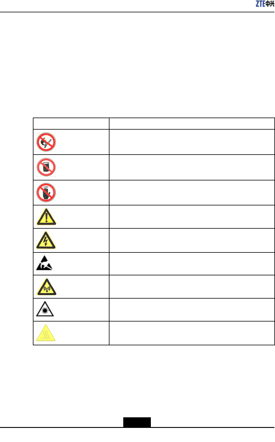
Table1-1SafetySymbolsDescription
SafetySymbolsMeaning
Nosmoking:Smokingisforbidden
Noammables:Noammablescanbestored.
Notouching:Donottouch.
Universalalertingsymbol:Generalsafetyattentions.
Electricshock:Riskofelectricshock.
Electrostatic:Thedevicemaybesensitivetostaticelectricity.
Microwave:Bewareofstrongelectromagneticeld.
Laser:Bewareofstronglaserbeam.
Scald:Bewareofscald.
Amongstthesesafetysymbols,theuniversalalarmsymbolsareclassiedintothreelevels:
danger,warning,andcaution.Theformatsandmeaningsofthethreelevelsaredescribed
asbelow:
1-2
SJ-20100722143906-002|02/20/2011(R1.3)ZTEProprietaryandCondential
Chapter1SafetyDescription
Danger!
Indicatesapotentiallyhazardoussituationwhich,ifnotavoided,willresultindeathor
seriousinjuryofpeople,orequipmentdamagesandbreakdown.
Warning!
Indicatesapotentiallyhazardoussituationwhich,ifnotavoided,couldresultindeathor
seriousinjury.
Caution!
Indicatesapotentiallyhazardoussituationwhich,ifnotavoided,couldresultinserious
injuries,equipmentdamagesorinterruptionofpartservices.
1.3SafetyInstructions
Thissectiondescribesthesafetyinstructionsrelatedtoelectricalsafety,antistatic,heavy
objectsandmodules.
ElectricalSafetyInstructions
Thefollowingaretheelectricalsafetyinstructionsabouttools,highvoltage,powercables,
holesandlightning:
lTools
Usespecialtoolsratherthancommontoolsforhigh-voltageandACoperations.
lHighVoltage
Danger!
Highvoltageishazardous.Directorindirectcontactwithhighvoltageormainsupply
usingawetobjectcouldresultindeath.
àStrictlyfollowlocalsafetyrulestoinstallACpowerdevices.
àInstallationstaffmustbequaliedforperforminghigh-voltageandACoperations.
1-3
SJ-20100722143906-002|02/20/2011(R1.3)ZTEProprietaryandCondential
ZXSDRR8860InstallationManual
àDonotwearanywatch,handchain,bracelet,ringoranyotherconductiveobjects
duringsuchoperations.
àPreventmoisturefromaccumulatingontheequipmentduringoperationsina
dampenvironment.
lPowerCable
Warning!
Neverinstalloruninstallpowercableswhiletheyarelive.Otherwise,thepowercable,
whencontactingaconductor,mayresultinsparksorelectricarccausingareoreven
damagetoeyes.
àMakesureofshuttingoffpowersupplybeforeinstallingordisconnectingapower
cable.
àBeforeconnectingthepowercable,makesurethattheconnectingcableandits
labelareappropriatefortheactualinstallationrequirements.
lDrillingHoles
Warning!
Itisnotallowedtodrillchassisholeswithoutpermission.
àUnqualieddrillingcoulddamagewiringandcablesinsidethechassis.
Additionally,metalpiecesinsidethechassiscreatedbythedrillingcouldresult
inashortcircuit.Useinsulationprotectionglovesandrstmovecablesinsidea
chassisawaywhendrillingisnecessaryonachassis.
àProtecteyesduringdrillingasdustoryingdebrismaydamageeyes.
àCleananydebrisintimeafterdrilling.
lLightning
Danger!
Donotperformhigh-voltage,AC,irontowerormastoperationsinathunderstorm.
Thunderstormswouldgiverisetoastrongelectromagneticeldintheatmosphere.
Therefore,theequipmentmustbegroundedandprotectedintimeagainstlightning
strikes.
1-4
SJ-20100722143906-002|02/20/2011(R1.3)ZTEProprietaryandCondential
Chapter1SafetyDescription
AntistaticSafetyInstructions
Caution!
Staticelectricityproducedbyhumanbodycandamagestatic-sensitivecomponentson
circuitboard,suchaslarge-scaleintegratedcircuits.
lFrictioncausedbyhumanbodyactivitiesistherootcauseofelectrostaticcharge
accumulation.Staticvoltagecarriedbyahumanbodyinadryenvironmentcanbe
upto30kV,andcanremainthereforalongtime.Anoperatorwithstaticelectricity
maydischargeelectricitythroughacomponentwhenhe/shetouchestheconductor
andcausingdamage.
lWearanantistaticwriststrap(theotherendofwriststrapmustbewellgrounded)
beforetouchingtheequipmentorholdingaplug-inboard,circuitboard,Integrated
Circuit(IC)chiporotherdevices,topreventhumanstaticelectricityfromdamaging
sensitivecomponents.
lTheantistaticwriststrapusedmustbesubjecttoregularcheck.Donotreplacethe
cableofanantistaticwriststrapwithanyothercables.
lDonotcontactstatic-sensitivemoduleswithanyobjectthateasilygeneratesstatic
electricity.Forexample,frictionofpackagebag,transferboxandtransferbeltmade
frominsulationplasticmaycausestaticelectricityoncomponents.Dischargeofstatic
electricitymaydamagecomponentswhentheycontactahumanbodyortheground.
lModulesshouldonlycontactmaterialssuchasanantistaticbag.Keepmodulesin
antistaticbagsduringstorageandtransportation.
lDischargestaticelectricityofthetestdevicebeforeuse,thatis,groundthetestdevice
rst.
lDonotplacethemodulenearastrongDCmagneticeld,suchasthecathode-ray
tubeofamonitor.Keepthemoduleatleast10cmaway.
HoistingHeavyObjects
Warning!
Whenhoistingheavyobjects,ensurethatnobodyisstandingorwalkingunderthehoisted
object.
lEnsurethehoistercanmeethoistingrequirementswhendisassemblingheavy
equipment,ormovingandreplacingequipment.
lTheinstallationpersonnelmustbedulytrainedandqualiedforhoistingoperations.
lHoistingtoolsmustbeinspectedandcompletebeforeservice.
1-5
SJ-20100722143906-002|02/20/2011(R1.3)ZTEProprietaryandCondential

ZXSDRR8860InstallationManual
lMakesurethathoistingtoolsarexedrmlyonasufcientlysecuredobjectorwall
beforethehoistingoperation.
lGivebrieforalinstructionsduringhoistingoperationstopreventanymishap.
Unplugging/PluggingaModule
lNeverplugamodulewithexcessiveforce,toensurethatthepinsonthebackplane
donotgetdeformed.
lPlugthemodulerightintotheslotandmakesuremodulecircuitfacesdonotcontact
eachotherlestanyshortcircuitmayoccur.
lKeephandsoffthemodulecircuit,components,connectorsandcabletroughwhen
holdingamodule.
RackMountSafetyInstructions
RackMountInstructions-Thefollowingorsimilarrack-mountinstructionsareincluded
withtheinstallationinstructions:
lElevatedOperatingAmbient-Ifinstalledinaclosedormulti-unitrackassembly,the
operatingambienttemperatureoftherackenvironmentmaybegreaterthanroom
ambient.Therefore,considerationshouldbegiventoinstallingtheequipmentinan
environmentcompatiblewiththemaximumambienttemperature(Tma)speciedby
themanufacturer.
lReducedAirFlow-Installationoftheequipmentinarackshouldbesuchthatthe
amountofairowrequiredforsafeoperationoftheequipmentisnotcompromised.
lMechanicalLoading-Mountingoftheequipmentintherackshouldbesuchthata
hazardousconditionisnotachievedduetounevenmechanicalloading.
lCircuitOverloading-Considerationshouldbegiventotheconnectionofthe
equipmenttothesupplycircuitandtheeffectthatoverloadingofthecircuitsmight
haveonovercurrentprotectionandsupplywiring.Appropriateconsiderationof
equipmentnameplateratingsshouldbeusedwhenaddressingthisconcern.
lReliableEarthing-Reliableearthingofrack-mountedequipmentshouldbe
maintained.Particularattentionshouldbegiventosupplyconnectionsotherthan
directconnectionstothebranchcircuit(e.g.useofpowerstrips).
OtherSafetyInstructions
Note:
Donotperformmaintenanceordebuggingindependently,unlessaqualiedpersonis
present.
lPerformanairtighttestbeforeRRUdelivery,andprohibitdisassemblingtheRRUon
site.
1-6
SJ-20100722143906-002|02/20/2011(R1.3)ZTEProprietaryandCondential

Chapter1SafetyDescription
lReplacinganypartsormakinganychangestotheequipmentmightresultinan
unexpecteddanger.Therefore,besurenottoreplaceanypartsorperformany
changestotheequipmentunlessauthorizedotherwise.
lDuetothatRRUisinhightemperatureduringrunning,theRRUshouldbeinstalled
insomeregionsoutofoperators'reachorstrictlyrestricted.
lContactZTEofceifyouhaveanyquestion,toensureyoursafety.
1-7
SJ-20100722143906-002|02/20/2011(R1.3)ZTEProprietaryandCondential

ZXSDRR8860InstallationManual
Thispageintentionallyleftblank.
1-8
SJ-20100722143906-002|02/20/2011(R1.3)ZTEProprietaryandCondential

Chapter2
InstallationOverview
TableofContents
ComponentstobeInstalled........................................................................................2-1
InstallationFlow.........................................................................................................2-1
InstallationPreparation...............................................................................................2-2
2.1ComponentstobeInstalled
ForZXSDRR8860,thefollowingcomponentswillbeinstalled:
lZXSDRR8860cabinetandcomponents
Note:
Theinnercablesandfunctionalmodules/boardsinthecabinetarealreadyinstalled
beforeequipmentdelivery.
lSunshield(usedfortheoutdoorZXSDRR8860installation)
lCables
lAntennafeedersystemincludingantenna,jumpersandfeeder
2.2InstallationFlow
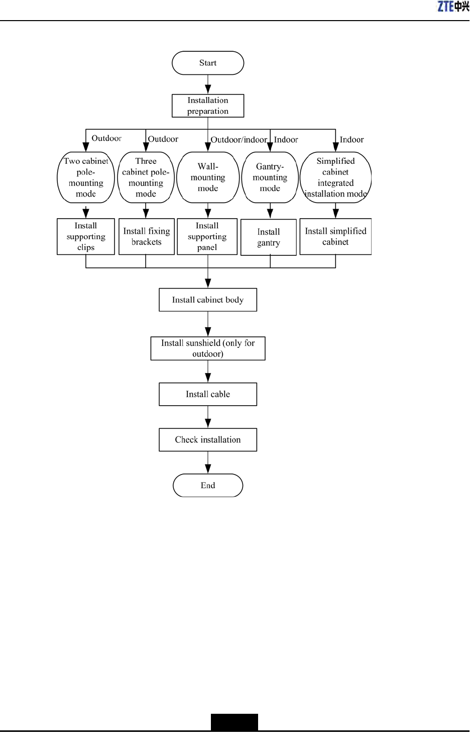
TheinstallationowofZXSDRR8860isdemonstratedinFigure2-1.However,itisnot
requiredtostrictlyfollowthestepsshowedinthisow.Theactualinstallationprocedures
dependontherequirementsonsite.
2-1
SJ-20100722143906-002|02/20/2011(R1.3)ZTEProprietaryandCondential
ZXSDRR8860InstallationManual
Figure2-1InstallationFlow
2.3InstallationPreparation
2.3.1EngineeringConditionInspection
Beforeinstallingdevices,followtherequirementsofEnvironmentAcceptanceReportand
checkinstallationenvironment.Thefollowingcontentisjustasareference.
InstallationPositionInspection
ZXSDRR8860installationpositionshouldaccordwiththerequirementsofengineering
design,thespeciedrequirementsasfollows:
lAvoiddusty,harmful-gasorexplosive-goodsenvironment;
2-2
SJ-20100722143906-002|02/20/2011(R1.3)ZTEProprietaryandCondential

Chapter2InstallationOverview
lAvoidtheplaceswithbigshockorstrongnoise;
lFarawaysubstation;
lFarawaypollutionsource;
lAvoidanindustrialboilerandheatingboiler;
lFarawayhigh-powerwirelessinterferencesource.
TemperatureandHumidityInspection
ZXSDRR8860temperatureandhumidityinworkenvironmentshouldmeetthe
requirements,asshownin
PowerSupplyInspection
TherequirementsofZXSDRR8860powersupplyaredescribedasfollows.
1.DCpowersupply:ZXSDRR8860is–48VDCpowersupplyandthevoltageofpower
supplyis–40VDC~–57VDC.
2.IndirectACpowersupply:adoptanoutdoorACunit(OAU);theOAUcanprovide220V
ACpowersupplyforoneZXSDRB8200C100andoneZXSDRR8860atthesame
time.
LightningInspection
TheZXSDRR8860lightningrequirementsaredescribedasfollows.
lOutdoorInstallation
1.ForDCpowersupply,congureanoutdoorDClightningboxOLP48-2.Ifthe
DCpowerisexportedfromtheequipmentroom,thelengthofpowercableis
morethan10m(lessthan50m)andtheoutputendofindoorDCpowerisnot
conguredwithB-levelorabovelightningdevices,itisrequiredtocongurean
indoorDClightningboxILP48–3intheequipmentroom.
2.ForindirectACpowersupply,itisrequiredtocongureanAClightningbox
(ZXPCScombinedarrester).
lForindoorinstallation,ifthepowercableisdistributedoutdoors,congurethepower
lightningboxaccordingtotheconditionsofoutdoorinstallation.
GroundingInspection
ZXSDRR8860adoptsanassociatedgroundingmode.Thevalueofgroundingresistance
isnotmorethan5ohm.
OtherInspections
1.ThecorollarydevicesorcomponentsshouldaccordwiththerequirementsofZXSDR
R8860engineeringdesigndrawing.
2.ThetransmissiondevicesinterconnectedwithBBUshouldhavebeenprepared.
2-3
SJ-20100722143906-002|02/20/2011(R1.3)ZTEProprietaryandCondential
ZXSDRR8860InstallationManual
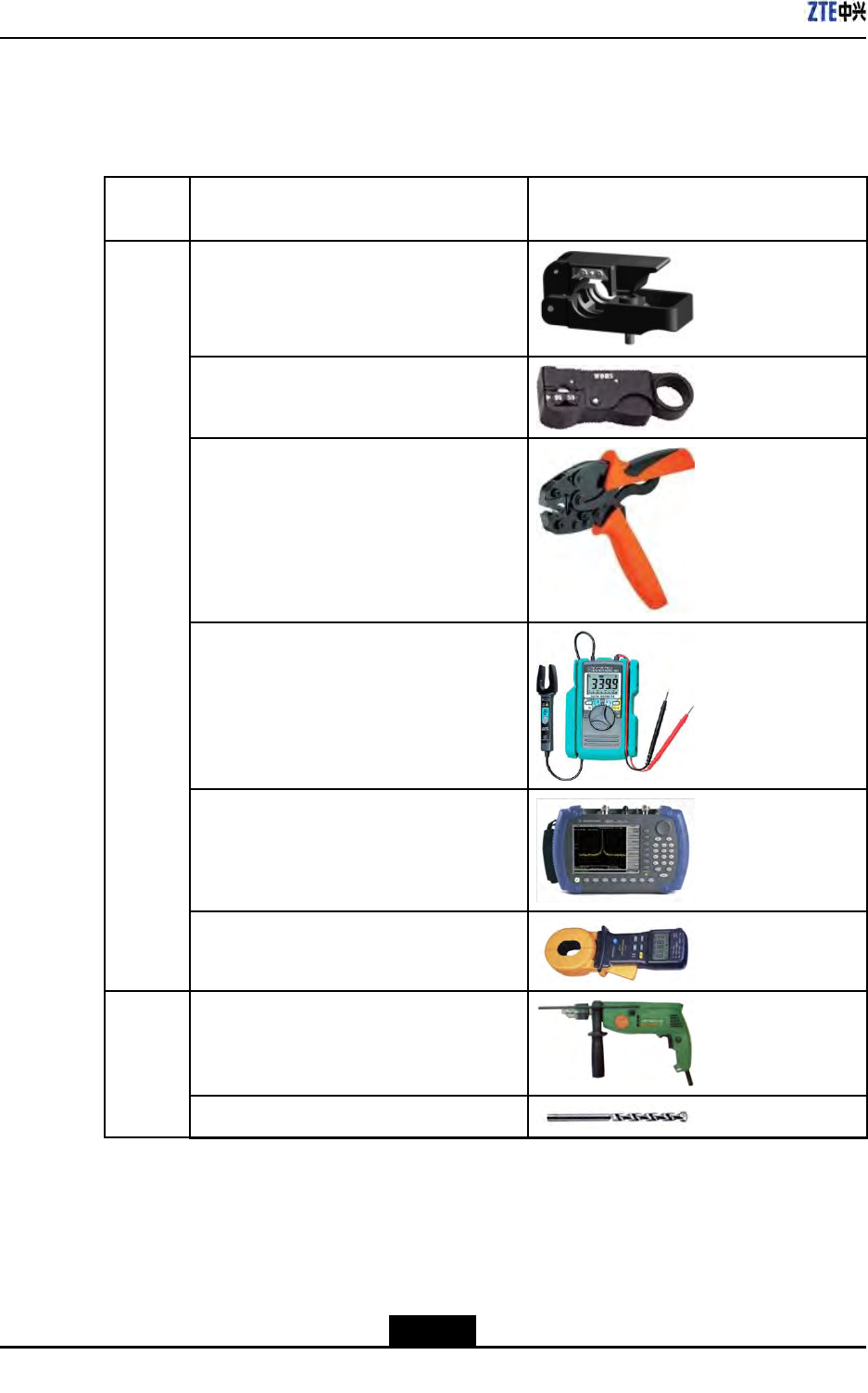
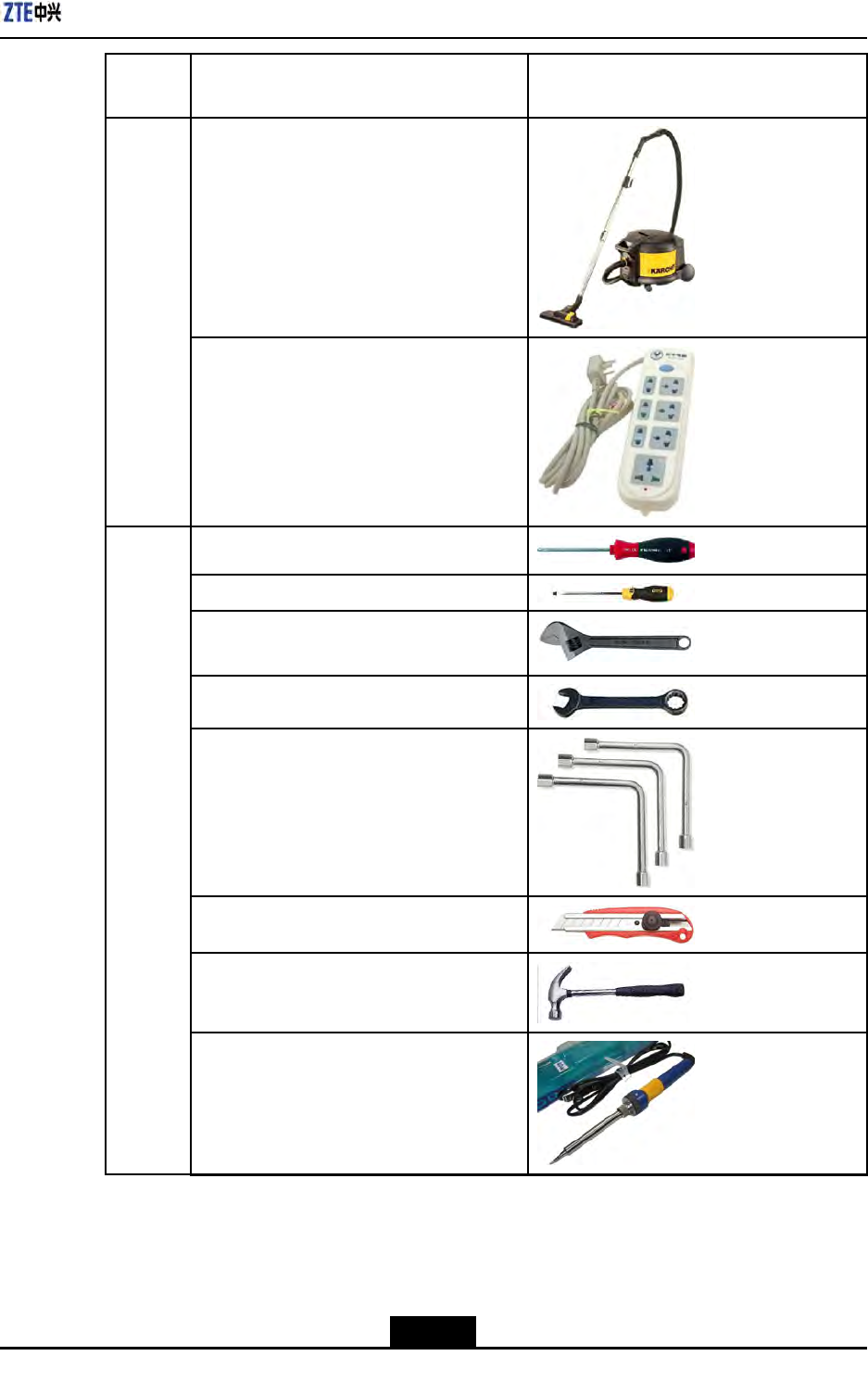
2.3.2ToolsandInstrumentsPreparation
Table2-1showstoolsandmeterslistrequiredduringinstallation.
Table2-1ToolandMeterList
Cate-
goryNameExample
Onefeederconnectorknife
One75Ωcoaxialcablestripper
Onemulti-functionalcrimpingpliers
Onemultimeter
Onestandingwaveratiotester
Special-
purpose
tools
Oneearthresistancetester
Oneelectricpercussiondrill
Severalauxiliarypercussiondrillbits
Punch-
ingtools
2-4
SJ-20100722143906-002|02/20/2011(R1.3)ZTEProprietaryandCondential
Chapter2InstallationOverview
Cate-
goryNameExample
Onevacuumcleaner
Powerconnectorboard(providingatleast3
two-phasesocketsand3three-phasesock-
ets,withthecurrentcapacitylargerthan15
A)
Crossscrewdrivers(4”,6”and8”each)
Flatheadscrewdrivers(4”,6”and8”each)
Adjustablewrenches(6”,8”,10”and12”
each)
Dual-purposewrenches(17”and19”each)
Onesetofsocketwrenches
Onepaperknife
5kgnailhammer
One300Wironandone40Wiron
General-
purpose
tools
2-5
SJ-20100722143906-002|02/20/2011(R1.3)ZTEProprietaryandCondential
ZXSDRR8860InstallationManual
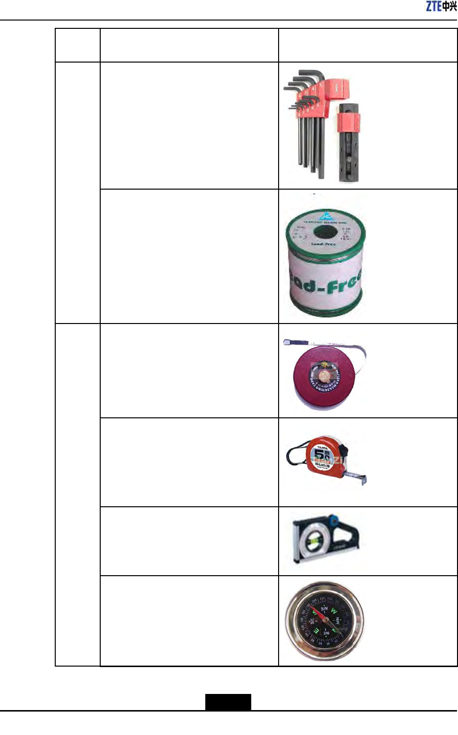
Cate-
goryNameExample
Onesetofinner-hexagonwrench
Solderwires
One50m(164feet)tapemeasure
One5m(16feet)steeltape
Oneangleinstrument
Onecompass
Mea-
sure-
ment
tools
2-6
SJ-20100722143906-002|02/20/2011(R1.3)ZTEProprietaryandCondential
Chapter2InstallationOverview
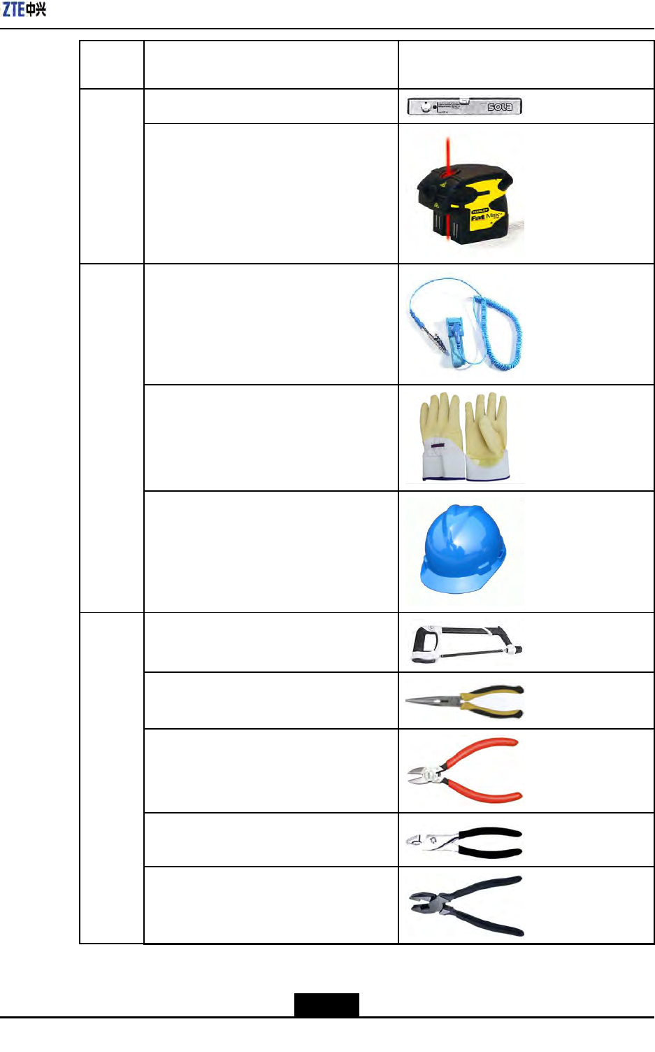
Cate-
goryNameExample
Onelevelbar
Oneplumb
Antistaticwriststrap
slip-proofgloves
Protec-
tiontools
Safetyhelmet
Onehacksaw(withseveralsawblades)
Onepairofsharp-nosepliers(8″)
Onepairofdiagonalpliers(8″)
Onepairofround-nosepliers(8″)
Onepairofvices(8″)
Clamp
tools
2-7
SJ-20100722143906-002|02/20/2011(R1.3)ZTEProprietaryandCondential
ZXSDRR8860InstallationManual
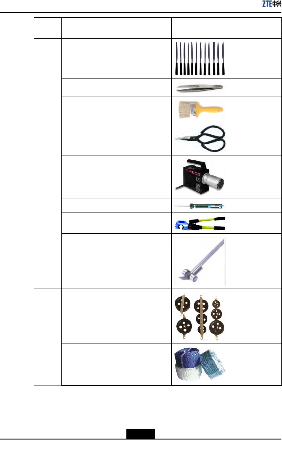
Cate-
goryNameExample
Onesetofneedleles(medium-sized)
Nippers
Onepaintbrush
Onepairofscissors
Onehotairblower
Onesolderremovaltool
Onehydrauliccrimper
Onecrowbar
Pulleyset
Rope
Auxiliary
tools
2-8
SJ-20100722143906-002|02/20/2011(R1.3)ZTEProprietaryandCondential
Chapter2InstallationOverview
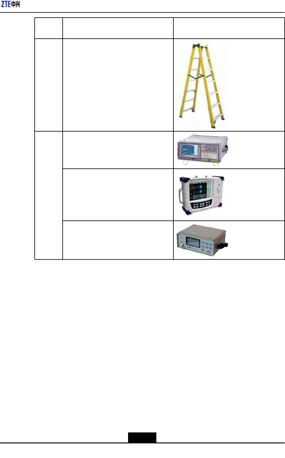
Cate-
goryNameExample
Ladder
Spectrumanalyzer(requiredincertainspe-
cialcases)
BTStester
Meters
Fieldstrengthtester(requiredincertainspe-
cialcases)
2.3.3On-siteDocuments
ZXSDRR8860installationneedsthefollowingtechnicaldocumentstobeready.
lZXSDRR8860EngineeringExplorationReport
lZXSDRR8860EnvironmentAcceptanceReport
ZXSDRR8860manualkitincludes:
lZXSDRR8860CommissioningandCongurationManual
lZXSDRR8860OperationandMaintenanceManual
lZXSDRR8860TechnicalManual
2-9
SJ-20100722143906-002|02/20/2011(R1.3)ZTEProprietaryandCondential

ZXSDRR8860InstallationManual
2.3.4UnpackingAcceptance
2.3.4.1CountingGoods
Context
Therepresentativeofcustomerandtheprojectsupervisormustbepresentonsitewhen
countingreceivedgoods.Ifeitherpartyisnotpresent,transportermustberesponsiblefor
theintactnessofthegoods.
Steps
1.ChecktheDeliveryChecklistofZTECorporation.Checkthetotalnumberofthegoods
andtheintactnessofthepackingboxes.Checkthepackinglisttoseeiftheplaceof
arrivalistheactualinstallationplace.Ifthegoodsareintact,unpackandinspectthem.
Note:
Itisrecommendedtounpackthegoodsabout30minutesafterreceipt,becausethere
isapossibilityofmoisturecontentduetotemperaturevariations.
2.Theequipmentinspectionlistandunpackingacceptancereportarepresentinthe
rstpackingcarton.Firstly,openrstthepackingcartonandtakeouttheUnpacking
AcceptanceReporttocheckwhetherthegoodsreceivedareinaccordancewiththe
inspectionlist.
3.Duringthecountingandunpackinginspectionprocess,ifanymaterialisfoundshort,
orgoodsdamaged,llintheUnpackingAcceptanceFeedbackTableandcontactZTE
promptly.
–EndofSteps–
2.3.4.2CrateUnpacking
Prerequisites
Preparetheappropriatetoolssuchasstraightscrewdriver,pliers,andcrowbar.
Context
Performthefollowingstepstoopenthecrate:
Steps
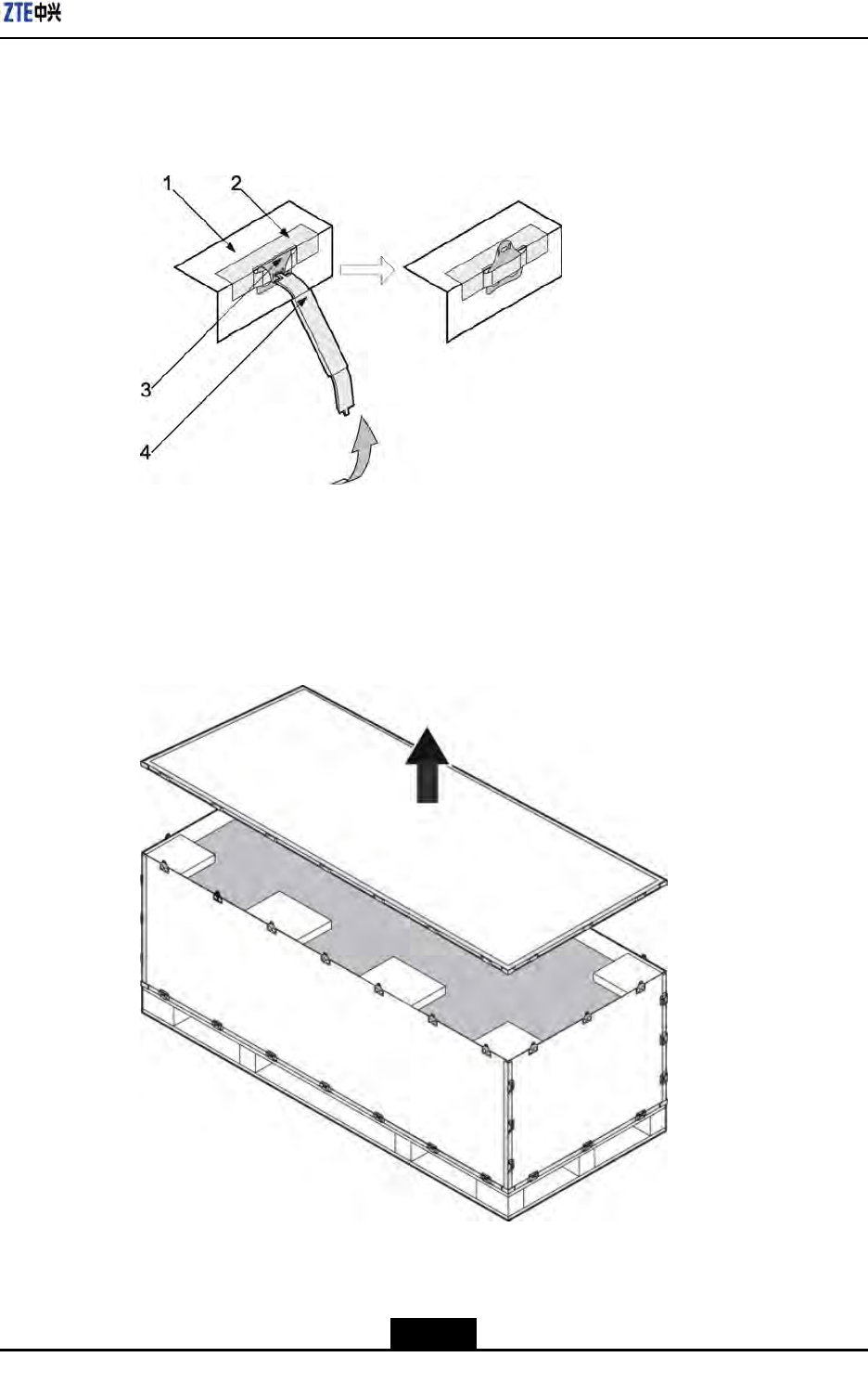
1.Insertaatheadscrewdriverornailhammerintothemetallatchofthecoverboardof
thecrate,andmovetheatheadscrewdriverornailhammertoloosentheironsheet.
2-10
SJ-20100722143906-002|02/20/2011(R1.3)ZTEProprietaryandCondential
Chapter2InstallationOverview
Thenusethecrowbarorpincerstoputthemetallatchinthestraightdirection,as
showninFigure2-2.
Figure2-2PuttingtheMentalLatchinStraightDirection
1.Mentalsheet
2.Coverboard
3.Mentallatch4.Flatheadscrewdriver
ornailhammer
2.Usethetoolstoputallthemetallatchesonthecoverboardofthecrate,andthen
removethecoverboardofthecrate,asshowninFigure2-3.
Figure2-3RemovingCoverBoard
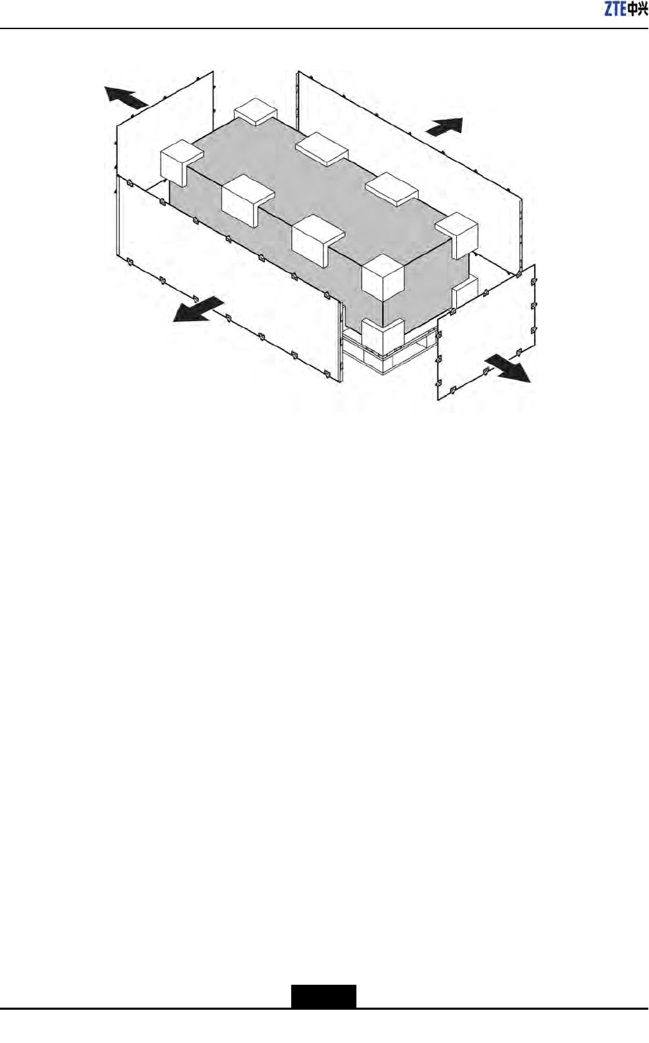
3.Puttheothermetallatchesonthefoursidesofthecrate,removetheboardsandtake
outtheequipmentfromthecrate,asshowninFigure2-4.
2-11
SJ-20100722143906-002|02/20/2011(R1.3)ZTEProprietaryandCondential
ZXSDRR8860InstallationManual
Figure2-4RemovingOtherBoards
–EndofSteps–
2.3.4.3CartonUnpacking
Prerequisites
Preparetheappropriatetoolssuchasstraightscrewdriver,diagonalpliers,andpaperknife.
Context
Performthefollowingstepstounpackthecarton:
Steps
1.Usediagonalplierstocutpackingstraps.
2.Useapaperknifetocutadhesivetapealongtheslitsoncartoncover,avoiddamaging
goodsinside.
3.Openthecarton,andremovethefoamboard.
4.Checkthegoodswithinthecarton.
5.Takeouttheantistaticpackingbag.
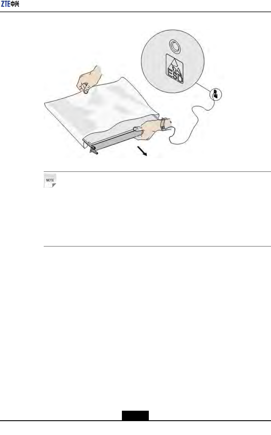
6.Opentheantistaticpackingbagtotakeouttheelectronicequipmentcomponents,as
showninFigure2-5.
2-12
SJ-20100722143906-002|02/20/2011(R1.3)ZTEProprietaryandCondential
Chapter2InstallationOverview
Figure2-5TakingOutComponentwithanAntistaticWristStrap
Note:
lAvoiddamagingtheantistaticbag(Itcanbeusedinthefutureforstorageofspare
parts)duringunpacking.
lWhiletheequipmentismovedtoahotteranddamperplace,waitfor30minutes
beforeunpackingtheequipment.Otherwise,moisturemaycondenseonthe
surfaceoftheequipmentandcausedamage.
lProperlydisposeofrecycledesiccants.
–EndofSteps–
2.3.4.4GoodsAcceptanceandHandover
Context
Performthisprocedureforacceptinggoods,andhandingthemovertooperators.
Steps
1.Acceptance
Basedonthename,categoryandnumbermentionedontheshippinglist,carefully
checkthegoodspiecebypiece.Makesurethatallgoodsmeetthefollowing
conditions:
a.Thereisnobubbly,peeling,nickandlthmarkonthesurfaceofthechassis.
b.Theoilpaintonthechassissurfaceisintact.
c.Allclampingscrewsaretightandintact.
2-13
SJ-20100722143906-002|02/20/2011(R1.3)ZTEProprietaryandCondential

ZXSDRR8860InstallationManual
d.Allcomponentsareproperlyinstalledinposition.
e.Theinspectedgoodsareplacedbycategory.
2.Handover
Aftercompletingtheunpackingprocedure,representativeofcustomerandproject
supervisorshouldapproveandsigntheUnpackingforInspectionReport.Bothparties
shouldhaveacopyofUnpackingforInspectionReport.
–EndofSteps–
2-14
SJ-20100722143906-002|02/20/2011(R1.3)ZTEProprietaryandCondential

Chapter3
CabinetInstallation
TableofContents
EngineeringIndices....................................................................................................3-1
Pole-mountedInstallationMode.................................................................................3-2
Wall-mountedInstallationMode................................................................................3-11
3.1EngineeringIndices
Table3-1describestheengineeringindicesofZXSDRR8860.
Table3-1ZXSDRR8860EngineeringIndices
ItemIndices
OverallDimensionWidthxHeightxDepth:320mmx500mmx172mm
UpperEnclosureDimensionWidthxHeightxDepth:320mmx370mmx72mm
LowerEnclosureDimensionWidthxHeightxDepth:320mmx500mmx100mm
Weight<22kg
Power-48VDC;-40V~-57V
220VAC:150V~285V/45Hz~65Hz(viaexternal
AC-to-DCconversionlightningbox)
WorkTemperature-40℃to55℃-40℉to131℉
WorkHumidity5%RH~95%RH
PowerConsumptionofNormalWork
Under-48VDCPowerSupply
l1Carrier
àOutputPower:20W/C/S
àPowerConsumption:160W
l2Carrier
àOutputPower:20W/C/S
àPowerConsumption:200W
l3Carrier
àOutputPower:20W/C/S
àPowerConsumption:250W
3-1
SJ-20100722143906-002|02/20/2011(R1.3)ZTEProprietaryandCondential
ZXSDRR8860InstallationManual
ThetechnicalindicesoftheindoorDClightningbox,exempliedby
JD40K085C20H2–K1Z,arelistedinT able3-2,whichissubjecttotheactualeld
technicalspecicationsforpracticalapplication.
Table3-2JD40K085C20H2–K1ZDCLightningBoxTechnicalIndices
ItemIndex
DimensionsWidthxHeightxDepth:400mmx450mmx100mm(The
heightoftopcoverboxlockexcluded)
NominalWorkingVoltage–48V
InstallationModeIndoorwall-mountinstallation
WorkingTemperature-5℃to70℃
WorkingHumidity≤95%RH
ThetechnicalindicesoftheexternalAC-to-DCconversionlightningbox,exempliedby
GPAD501M54-1A,arelistedinTable3-3,whichissubjecttotheactualeldtechnical
specicationsforpracticalapplication.
Table3-3GPAD501M54-1AExternalAC-to-DCConversionLightningBoxTechnical
Indices
ItemIndex
DimensionsWidthxHeightxDepth:217mmx288mmx127mm
Weight4.65kg
InputVoltageMin.value:150V
Typicalvalue:220V
Max.value:285V
InputFrequencyMin.value:45Hz
Typicalvalue:50Hz
Max.value:65Hz
InstallationModePole-mountandwall-mountinstallation
WorkingTemperature-40℃+65℃
WorkingHumidity5%95%
3.2Pole-mountedInstallationMode
3.2.1ComponentsUsedinPole-mountInstallation
Themaincomponentsusedinpole-mountinstallationinclude:
lPoleanchorclampcomponents;
lPolexingbracketcomponents.
3-2
SJ-20100722143906-002|02/20/2011(R1.3)ZTEProprietaryandCondential

Chapter3CabinetInstallation
Thepoleanchorclampcomponentsareusedforpole-mountinstallationofoneortwo
ZXSDRR8860s.Thepolexingbracketcomponentsareusedforpole-mountinstallation
ofthreeZXSDRR8860s.
Themainpoleanchorclampcomponentsusedinpole-mountinstallationforsingleZXSDR
R8860arelistedinTable3-4
Table3-4MainComponentList1
NameQuantity
Shortanchorclamp2
Longanchorclamp2
Standardspringwasher104
M10×120hexagonheadbolt(fullthread)4
I-typecommonM10hexagonalnut4
Flatwasher104
Standardspringwasher84
M8×40hexagonheadbolt4
Bigwasher84
Themainpoleanchorclampcomponentsusedinpole-mountinstallationfortwoZXSDR
R8860arelistedinT able3-5
Table3-5MainComponentList2
NameQuantity
Longanchorclamp4
Standardspringwasher104
M10×120hexagonheadbolt(fullthread)4
M10×80hexagonheadbolt(fullthread)4
I-typecommonM10hexagonalnut4
Flatwasher104
Standardspringwasher88
M8×40Hexagonheadbolt8
Bigwasher88
Themainpolexingbracketcomponentsusedinpole-mountinstallationforthreeZXSDR
R8860arelistedinTable3-6
3-3
SJ-20100722143906-002|02/20/2011(R1.3)ZTEProprietaryandCondential
ZXSDRR8860InstallationManual
Table3-6MainComponentList3
NameQuantity
Polexingbracket4
Standardspringwasher104
M10×120hexagonheadbolt(fullthread)4
I-typecommonM10hexagonalnut4
Flatwasher104
Standardspringwasher812
M8×40hexagonheadbolt12
Bigwasher812
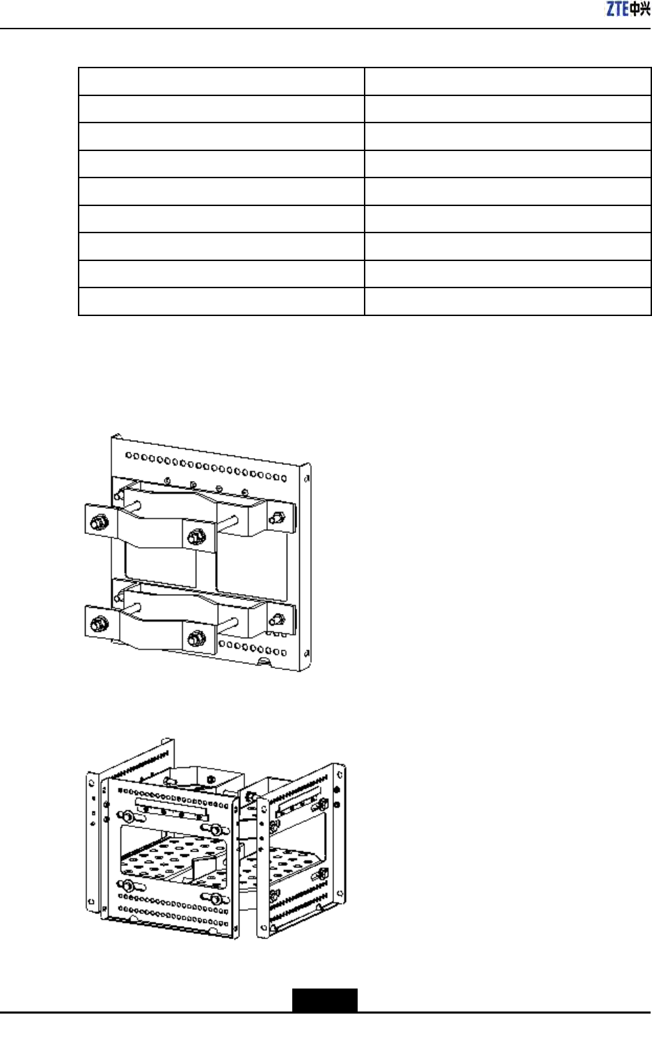
Figure3-1illustratespoleanchorclampcomponents.Figure3-2illustratespolexing
bracketcomponents.
Figure3-1PoleAnchorClampComponents
Figure3-2PoleFixingBracketComponents
3-4
SJ-20100722143906-002|02/20/2011(R1.3)ZTEProprietaryandCondential
Chapter3CabinetInstallation
Note:
ThepoleanchorclampcomponentsshowninFigure3-1isadoptedinonepole-mount
installation.Thepoleanchorclampcomponentsusedintwopole-mountinstallationonly
changestwoshortanchorclampsintotwolonganchorclamps,thespeciclistdescribed
inT able3-5
3.2.2InstallingSingleCabinetonPole(Pole–Mount)
Context
ThistopicdescribesthemethodtoxasingleZXSDRR8860cabinetonapole.
Steps
1.Installpoleanchorclampcomponents.
a.Fixanchorclampsontothepole,andaligntheanchorclampholesandscrewthe
boltsabit;
b.Adjustthespacebetweentheclipsbasedonthescrew'spositionofsupporting
panel,andxthesupportingpanelontheclipswithM8boltsandtightenitproperly;
c.ScrewdownM10boltstightly.
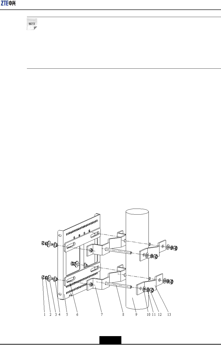
Figure3-3illustratestheinstallationofanchorclampcomponents.
Figure3-3Pole-MountInstallation(1)
1.M8×40hexagonhead
bolt
2.Standardspring
washer
3.Bigflatwasher
4.Insulationflange
3-5
SJ-20100722143906-002|02/20/2011(R1.3)ZTEProprietaryandCondential
ZXSDRR8860InstallationManual
5.Supportingpanel
6.Insulationboard
7.Longanchorclamp
8.M10×120hexagon
headbolt(fullthread)
9.Pole
10.Flatwasher
11.Standardspring
washer
12.I-typecommonM10
hexagonalnut
13.Shortanchorclamp
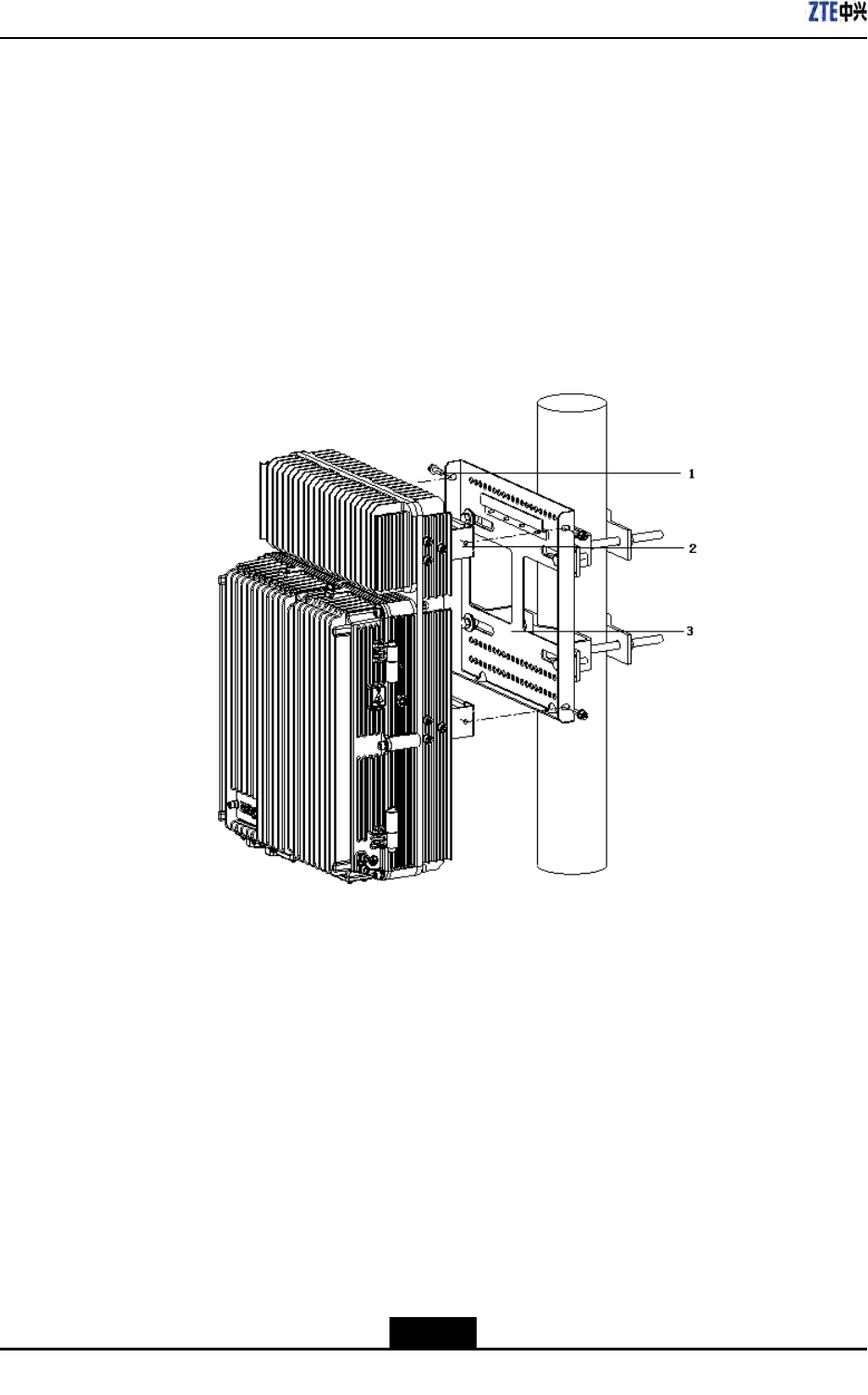
2.MounttheZXSDRR8860cabinetonthesupportingpanelandfastenthecabinetwith
fourM6X20hexagonsocketcapscrewsasshowninFigure3-4
Figure3-4Pole-MountInstallation(2)
1.M6Screw2.Retainingboard3.Supportingpanel
–EndofSteps–
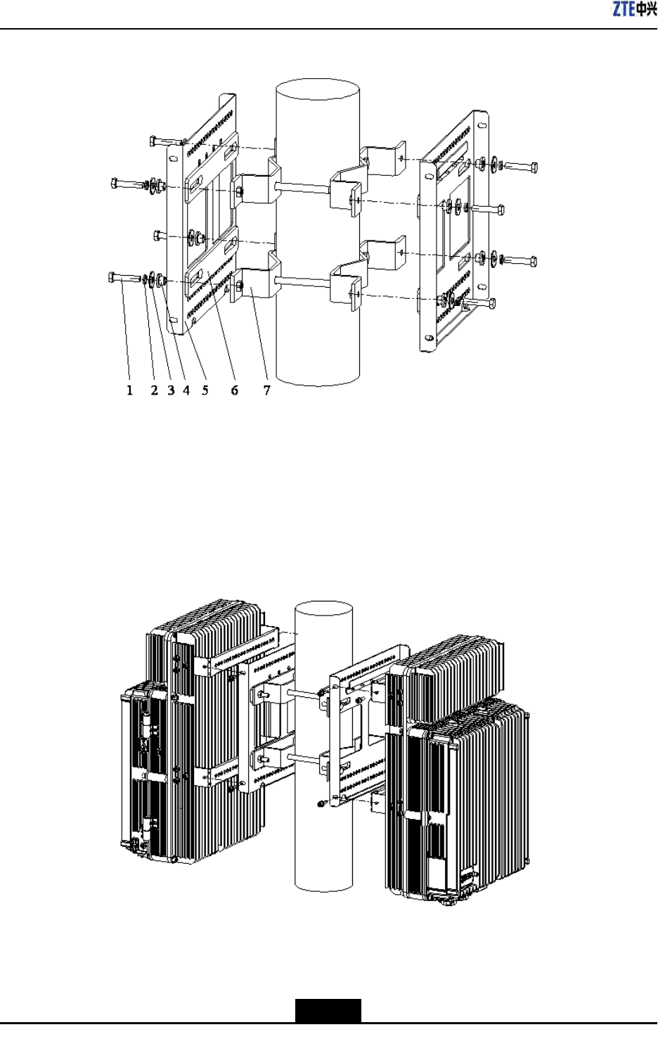
3.2.3InstallingTwoZXSDRR8860Pole-mountCabinets
Steps
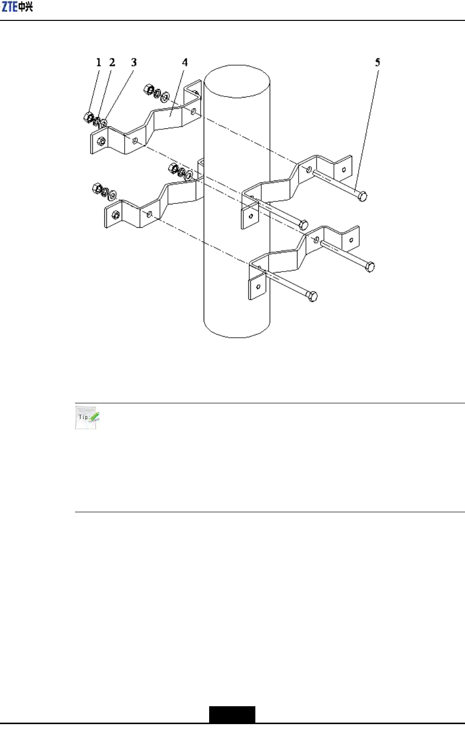
1.Fixanchorclampsbacktobackontothepole,andaligntheholesandscrewdowna
bitwithbolts.Adjustspacebetweenanchorclampsbasedonthescrews'positionof
supportingpanelasshowninFigure3-5.
3-6
SJ-20100722143906-002|02/20/2011(R1.3)ZTEProprietaryandCondential
Chapter3CabinetInstallation
Figure3-5Pole-mountInstallation(1)
1.I-typecommonM10
hexagonalnut
2.Standardspring
washer10
3.Bigflatwasher10
4.Longanchorclamp
5.M10×120hexagon
headbolt(fullthread)
Tip:
DuringtwoZXSDRR8860cabinetinstallation,thesuggestedpolediameteris60to
120mmandtherearetwokindsofboltlengths:
lUsetheboltoflength80mmforpolediameterof60mmto90mm;
lUsetheboltoflength120mmforpolediameterof90mmto120mm.
2.FixtwosupportingpanelsontheanchorclampwithM8boltsandscrewM10bolts
tightly,asshowninFigure3-6.
3-7
SJ-20100722143906-002|02/20/2011(R1.3)ZTEProprietaryandCondential
ZXSDRR8860InstallationManual
Figure3-6Pole-mountInstallation(2)
1.M8×40Hexagonhead
bolt
2.Standardspring
washer8
3.Bigflatwasher8
4.Insulationflange
5.Supportingpanel
6.Insulationboard
7.Longanchorclamp
3.MountthetwoZXSDRR8860cabinetsonthesupportingpanelandfastenthecabinet
withfourM6×20hexagonsocketcapscrewsasshowninFigure3-7.
Figure3-7Pole-mountInstallation(3)
–EndofSteps–
3-8
SJ-20100722143906-002|02/20/2011(R1.3)ZTEProprietaryandCondential
Chapter3CabinetInstallation
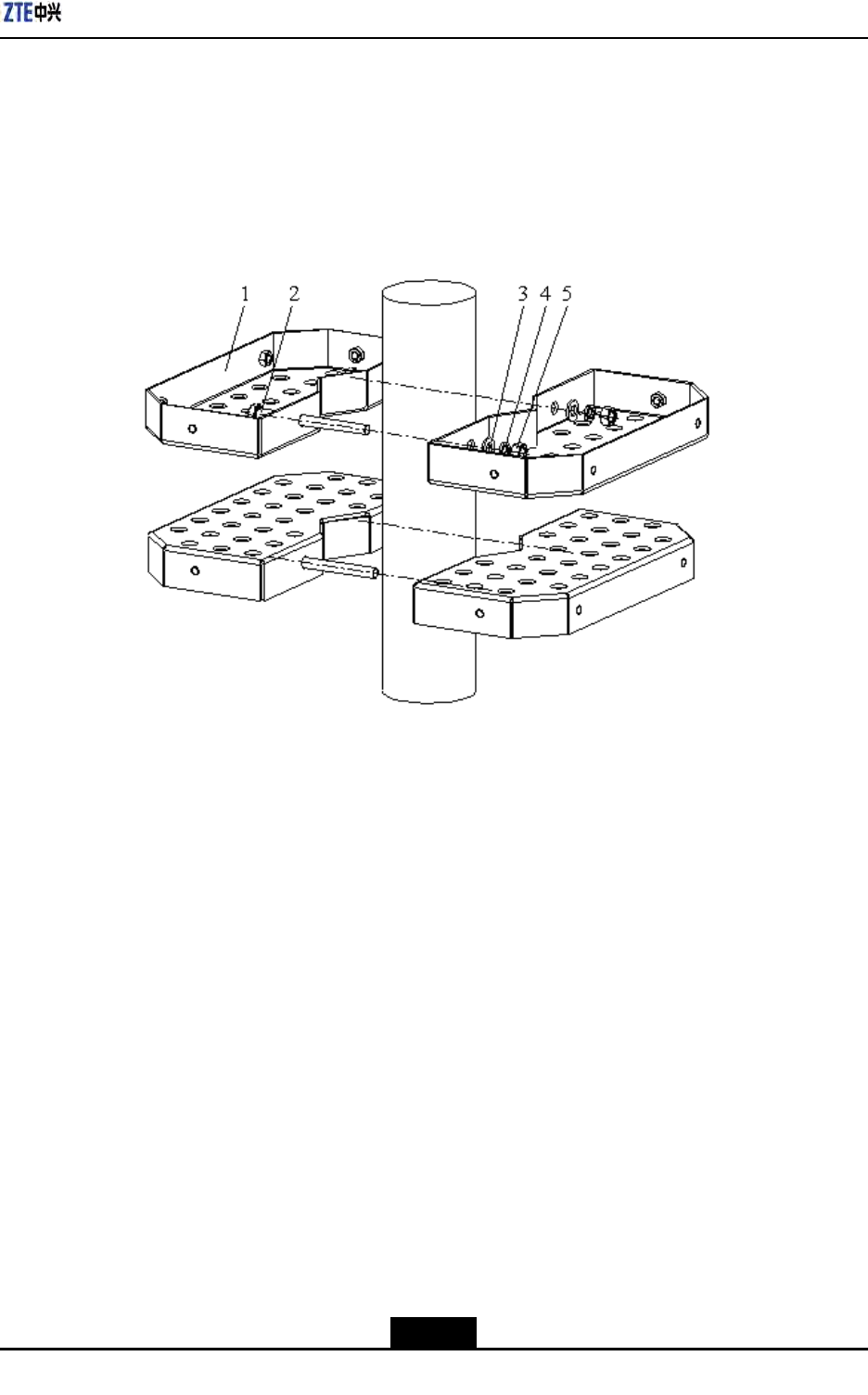
3.2.4InstallingThreeZXSDRR8860CabinetsonPole
Steps
1.Fixthetwosetsofxingbracketsontothepoleandaligntheholesandscrewitabit
withbolts,asshowninFigure3-8.
Figure3-8Pole-mountInstallation(1)
1.FixingBracket
2.M10×120hexagon
headbolt(fullthread)
3.Standardspring
washer10
4.Flatwasher10
5.I-typecommonM10
hexagonalnut
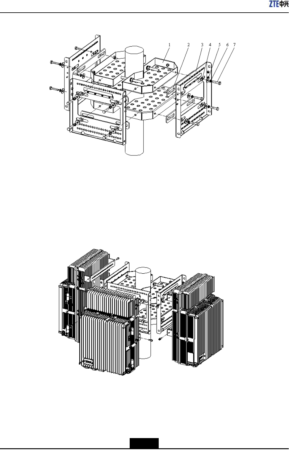
2.Adjustspacebetweenthexingbracketsbasedonthescrews'positionofinsulation
boardsatthebackofsupportingpanelsasshowninFigure3-9.Fixthreesupporting
panelsonthexingbracketswithM8bolts.ScrewthexingbracketswithM10bolts.
3-9
SJ-20100722143906-002|02/20/2011(R1.3)ZTEProprietaryandCondential
ZXSDRR8860InstallationManual
Figure3-9Pole-mountInstallation(2)
1.Fixingbracket
2.Insulationboard
3.Supportingpanel
4.Insulationflange
5.Bigflatwasher8
6.Standardspring
washer8
7.M8×40Hexagonhead
bolt
3.MounttheZXSDRR8860cabinetsonthesupportingpanelsandfastenthecabinets
withM6×20hexagonsocketcapscrewsasshowninFigure3-10.
Figure3-10Pole-mountInstallation(3)
3-10
SJ-20100722143906-002|02/20/2011(R1.3)ZTEProprietaryandCondential
Chapter3CabinetInstallation
Tip:
Thesidewithoutxingbracketcanbelocatedalongthewall.
–EndofSteps–
3.3Wall-mountedInstallationMode
3.3.1ComponentsUsedinWall-MountInstallation
Thecomponentsusedinwall-mountinstallationarelistedinT able3-7
Table3-7MainComponents
NameQuantity
Supportingpanel1
Drilltemplate1
M8×80expansionbolt4
Bigwasher84
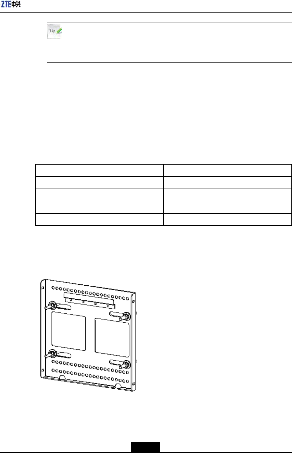
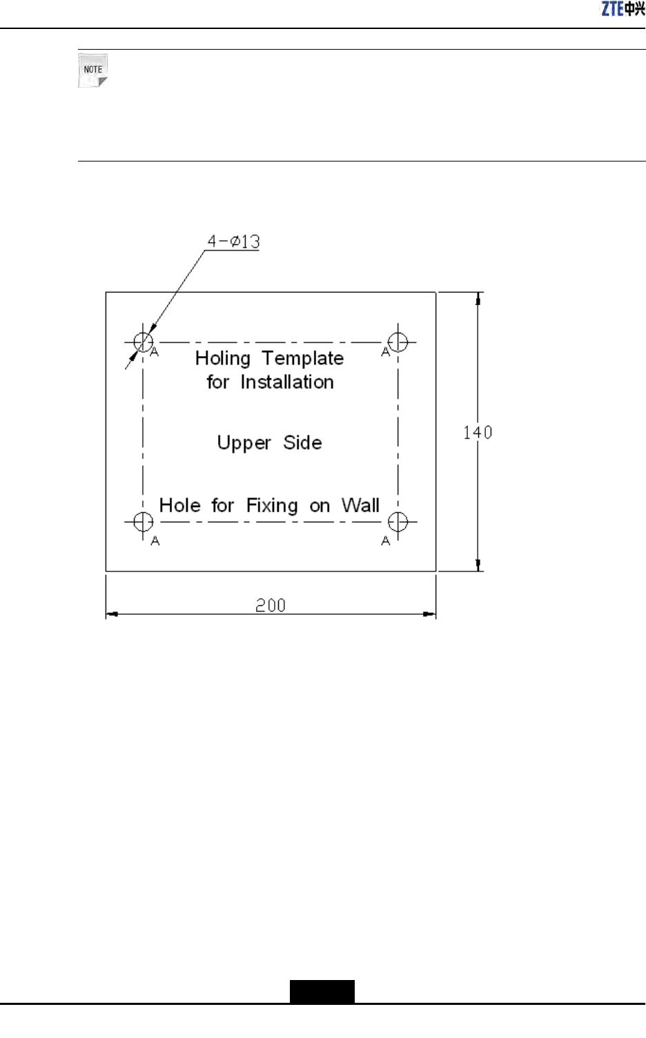
ThesupportingpanelisshowninFigure3-11.Theholemarkingdesigntemplateisshown
inFigure3-12.
Figure3-11SupportingPanel
3-11
SJ-20100722143906-002|02/20/2011(R1.3)ZTEProprietaryandCondential
ZXSDRR8860InstallationManual
Note:
Thesupportingpanel,asthecommoncomponentinZXSDRR8860installation,isused
inthewall-mount,pole-mountandgantry-mountinstallationmodes.
Figure3-12HoleMarkingDesignTemplate(Unit:mm)
3.3.2InstallingCabinetonWall(Wall-Mount)
Context
Figure3-13illustratesthespacerequirement(Unit:mm)forwall-mountinstallation.
3-12
SJ-20100722143906-002|02/20/2011(R1.3)ZTEProprietaryandCondential
Chapter3CabinetInstallation
Figure3-13SpaceRequirementforWall-mountInstallation(Unit:mm)
Steps
1.Firstlymarktheholepositionsonthewallwithholedesigntemplate.Drillthemarked
pointsabout60mmwithpercussivedrillandinstalltheexpansionbolts.
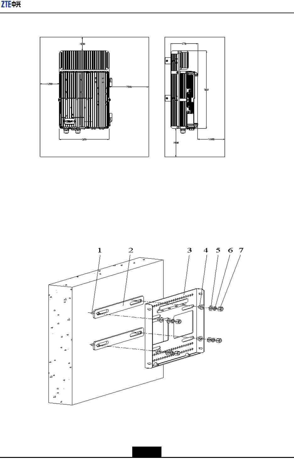
2.FixthesupportingpanelonthewallwithboltsasshowninFigure3-14
Figure3-14SupportingPanelInstallationonWall
1.M8×80expansionbolt
2.Insulationboard
3.Supportingpanel
4.Insulationflange
5.Bigflatwasher8
6.Standardspringmat8
7.M8nut
3-13
SJ-20100722143906-002|02/20/2011(R1.3)ZTEProprietaryandCondential
ZXSDRR8860InstallationManual
l
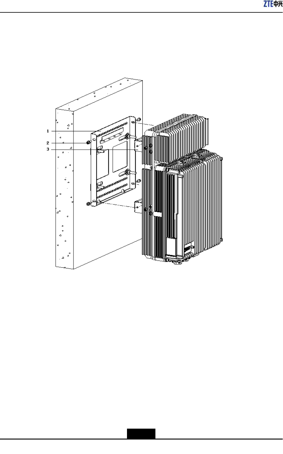
3.MounttheZXSDRR8860cabinetontothesupportingpanel,andfastenthecabinet
withfourM6X20hexagonsocketcapscrewsasshowninFigure3-15.
Figure3-15MountingCabinet
1.Supportingpanel2.M6safeguardscrew3.Retainingboard
–EndofSteps–
3-14
SJ-20100722143906-002|02/20/2011(R1.3)ZTEProprietaryandCondential

Chapter4
ExternalCableInstallation
TableofContents
ExternalCableLayout................................................................................................4-1
ExternalCableInstallationFlow.................................................................................4-2
Specicationsof1+3+3WaterproofProcessingwithPlasterandTape.......................4-4
InstallingPowerCable................................................................................................4-6
InstallingGroundingCable.........................................................................................4-7
InstallingFiberbetweenBBUandRRU......................................................................4-9
InstallingFiberbetweenRRUandRRU....................................................................4-10
InstallingEnvironmentMonitoringCable...................................................................4-12
InstallingAISGControlCable...................................................................................4-13
InstallingFrequencyPointExtensionCable..............................................................4-14
InstallingJumper......................................................................................................4-15
InstallingPIMDC......................................................................................................4-16
4.1ExternalCableLayout
TheconnectionrelationshipofZXSDRR8860externalcablesisdescribedinT able4-1.
Table4-1ZXSDRR8860ExternalCableConnectionRelationship
NameConnectionRelationshipDescription
PowercableConnectstheZXSDR
R8860powerinterface(DCIN)
tothepowersupplyequipment
interface
Oneendistheaviationplugand
theotherendisreservedfor
powercablemadeonsite.The
lengthofcableisbasedonthe
engineeringsurvey.
GroundingcableConnectsoneZXSDR
R8860groundbolttothe
copperbar
Thegroundingcableismade
upofstrandsofame-retardant
wire.Thecrosssectionalarea
ofZXSDRR8860grounding
cableis10mm2.Thecolorof
groundingcableisyellowand
green.Copperlugsarecrimped
atbothendsoftheZXSDR
R8860groundingcable.
4-1
SJ-20100722143906-002|02/20/2011(R1.3)ZTEProprietaryandCondential

ZXSDRR8860InstallationManual
NameConnectionRelationshipDescription
OpticalFiberTherearetwotypesofZXSDR
R8860ber:BBUconnection
/ZXSDRR8860cascading.
TherearetwotypesofZXSDR
R8860opticalber:oneusedin
BBUconnectionandtheother
usedincascadingbetween
ZXSDRR8860s.
EnvironmentmonitoringcableConnectstheZXSDR
R8860environmentmonitoring
interfaceMONtotheexternal
monitoringcomponentsorthe
drycontact.
Aendoftheenvironment
monitoringcableisPINdesign.
Bend,with3mlengthintotal,
needsmakingbasedonthe
on-siteengineering.
AISGcontrolcableConnectstheZXSDR
R8860debugginginterface
(AISG)tothecontrolinterfaceof
electrical-adjustmentantenna.
AISGisusedforcontrolofthe
electrical-adjustmentantenna.
Frequencypointextension
cable
InterconnectstheZXSDRR8860
RXin/RXoutinterfaces.
Thefrequencypointextension
cableusuallyadoptsthenished
1/2″jumperwith2mlength.The
jumpercanbeself-madebased
onthereal-timeconditionon
site.
AandBendsofjumperareN
connectors(male).
Antenna,feederandjumperConnectstheZXSDRR8860to
themainfeeder.
TheRFjumperusuallyadopts
thenished1/2″jumperwith
2mlength.Thejumpercan
beself-madebasedonthe
real-timeconditiononsite.
TheendofjumperisN
connector(male)andtheother
endisDINconnector(female).
4.2ExternalCableInstallationFlow
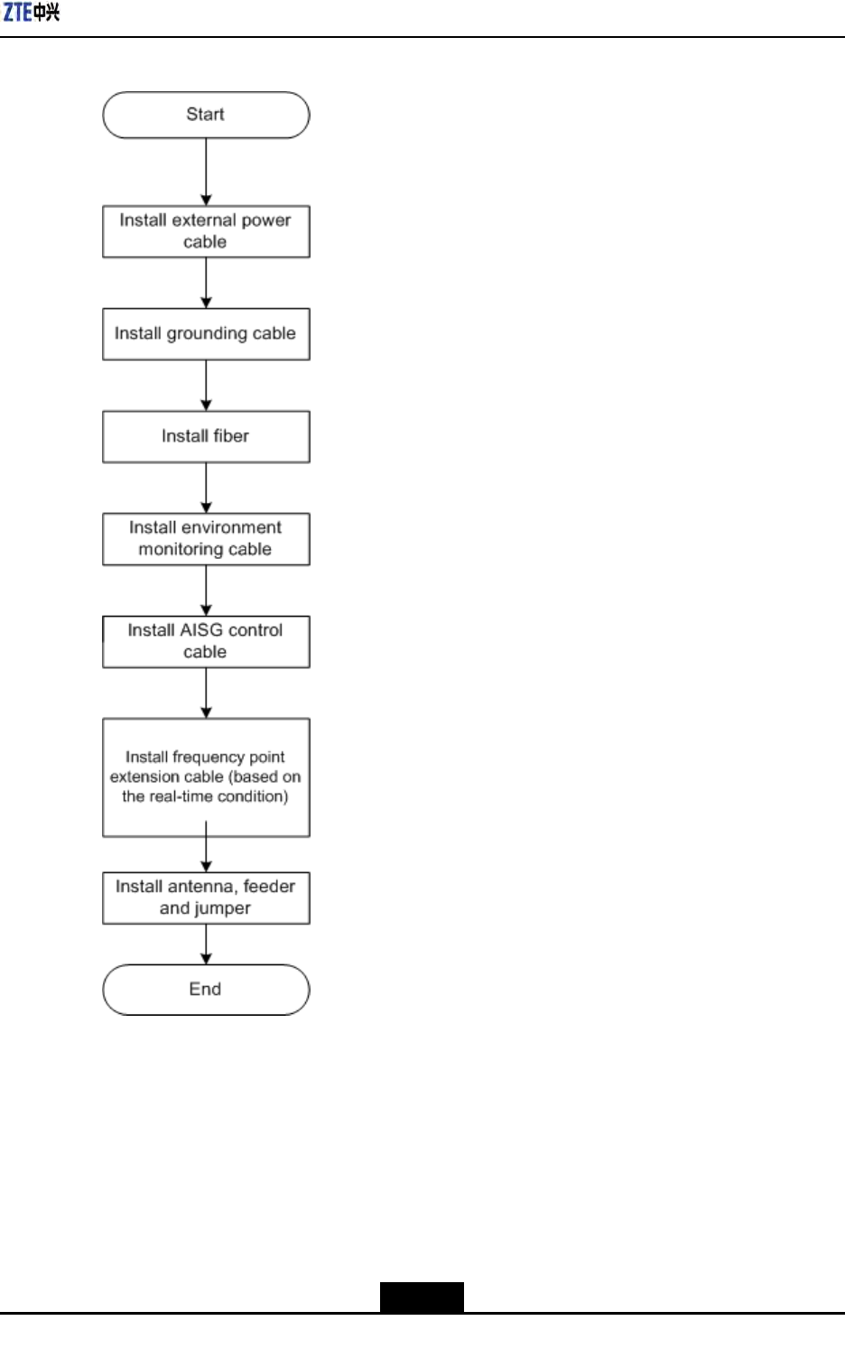
Figure4-1liststheinstallationowofexternalcable.Thisowcanbeadjustedbasedon
thereal-timecondition.
4-2
SJ-20100722143906-002|02/20/2011(R1.3)ZTEProprietaryandCondential
Chapter4ExternalCableInstallation
Figure4-1ExternalCableInstallationFlow
4-3
SJ-20100722143906-002|02/20/2011(R1.3)ZTEProprietaryandCondential
ZXSDRR8860InstallationManual
4.3Specificationsof1+3+3WaterproofProcessing
withPlasterandTape
Overview
Waterproofprocessingmustbeperformedonalltheoutdoormetalconnectorsofthe
RRUs.Theconnectorsinclude:thegroundingcableconnector,feederconnector,optical
berconnector,powercableconnector,anddrycontactconnectingcableconnector.
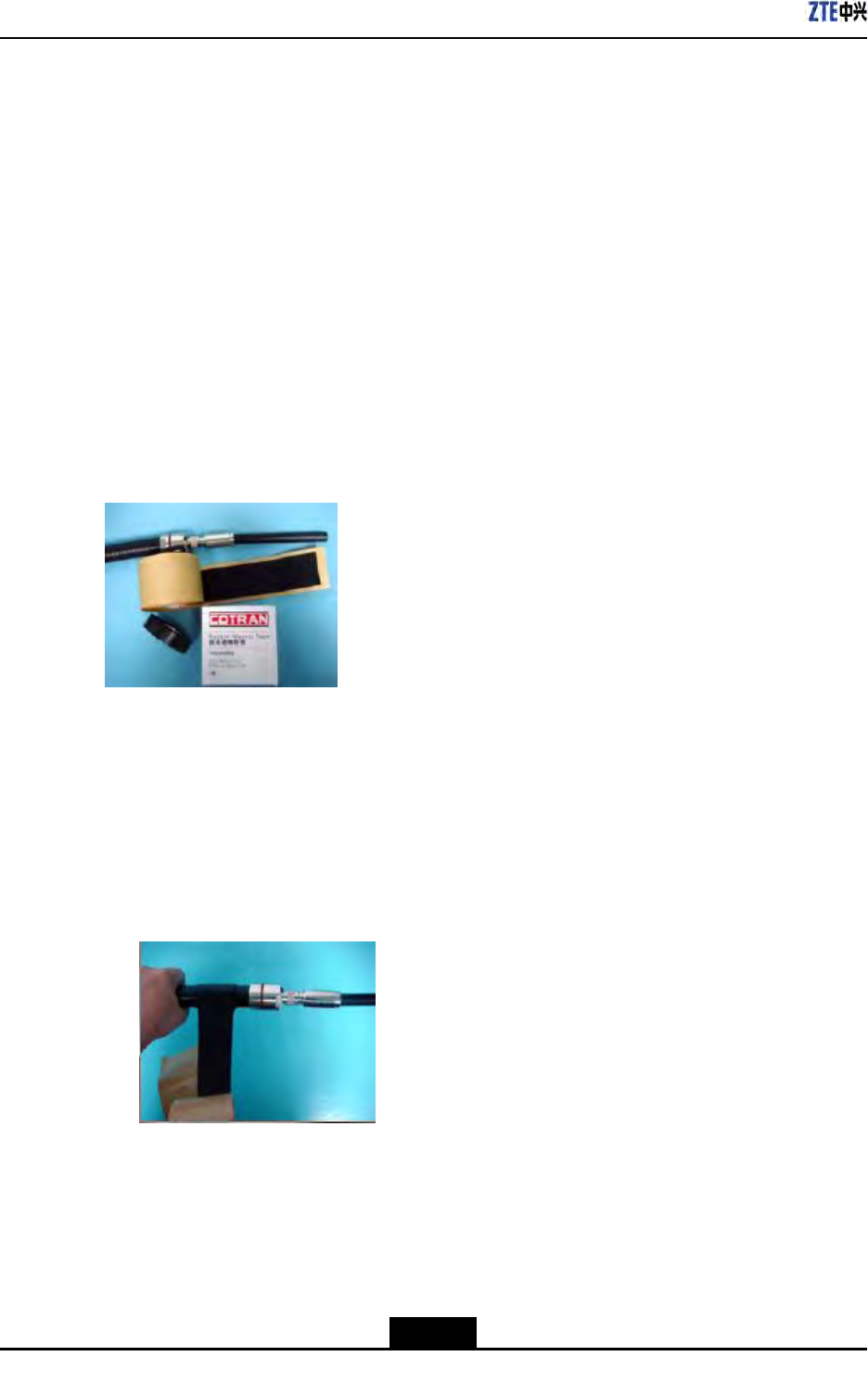
In1+3+3plasterandtapewaterproofprocessing,thewaterproongself-adhesive
insulatedtape(plasterforshort)+electricalinsulatedtape(tapeforshort)+UV-stabilized
cablefastenersontwoendsareadopted.Thisis1+3+3waterproofprocessing,namely,
1layeroftape+3layersofplaster+3layersoftape.Figure4-2showstheplasterand
tape.
Figure4-2AppearanceofthePlasterandTape
OperationProcedure
1.Cleantheconnectorsandthepartofthecablesurfacesthatistobesealed.
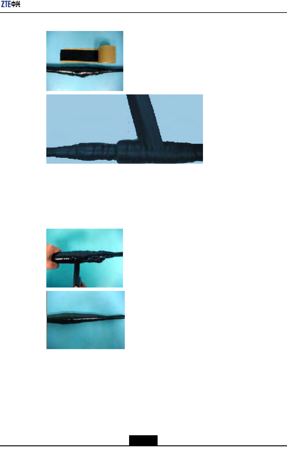
2.Tosimplifyremovalofthe1+3+3waterproofmaterialasawholeinfuturemaintenance,
wrapalayeroftapewiththestrengthofunwrappingthetapefrombottomtotop,
overlappingeachturn50percent,asshowninFigure4-3.
Figure4-3WrappingaLayerofTape
3.Unwraptheplaster,andpeelthepaperbacking.Then,extendtheplastertooneto
twotimestheoriginalsize,facethestickyside(fromwhichsidethepaperbackingis
removed)totheconnectororcable,andthenapplythreelayersofplaster,frombottom
totop,fromtoptobottom,andfrombottomtotop.Overlapeachturn50percent.Use
yourngerstomoldtheplastersothattheplasterbetweenthreelayersiswellbond,
asshowninFigure4-4.
4-4
SJ-20100722143906-002|02/20/2011(R1.3)ZTEProprietaryandCondential
Chapter4ExternalCableInstallation
Figure4-4WrappingThreeLayerofPlaster
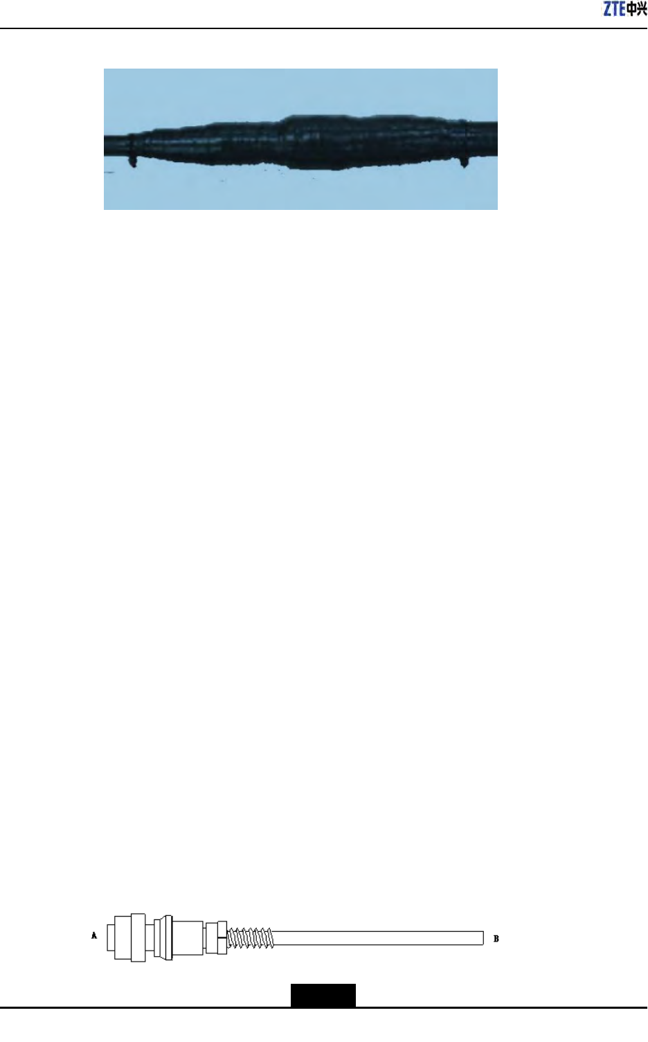
4.Withthestrengthofunwrappingthetape,wrapthreelayersoftape,frombottomto
top,fromtoptobottom,andfrombottomtotop,overlappingeachturn50percent.Use
yourngerstomoldthetapesothattheplasterandtapearewellbond,asshownin
Figure4-5.
Figure4-5WrappingaLayerofTape
5.Onthetwoend,tightlybindUV-stabilizedcablefastenerstothetape(underwhich
thereareplasterlayers)topreventremovalofthetape,asshowninFigure4-6.
4-5
SJ-20100722143906-002|02/20/2011(R1.3)ZTEProprietaryandCondential
ZXSDRR8860InstallationManual
Figure4-6BindingCableFasteners
Note
1.Wrapthetapewiththestrengthofunwrappingthetape(thatis,thestrengthofnaturally
unwrappingthetape).Thetapeshouldnotbeextended.
2.Extendtheplastertoonetotwotimestheoriginalsizewhilewrapping.
3.Overlapeachturnofthetapeandplasteratleast50percent.
4.Thedirectionsoftheplasterandtapeshouldbethesame.Thedirectionmustbegood
forfasteningthescrew.Thispreventsshrinkoftheextendedplasterfromloosening
theconnector.
5.Onthetwoends,overlaptheplasterandtapeforoneturn(whenchangingthe
wrappingdirection).
6.Afterwrapping,useyourngerstomoldtheplastersothattheplasterbetweenthe
layersiswellbond.
7.Thewrappinglengthofthetapemustbe(about10mm)longerthanthatofplaster,
especiallyonthecableend.Ensurethattheplasterisoverthetapesothatthe1+3+3
waterproofmaterialcanberemovedasawholeinfuturemaintenancewithcables
undamaged.
8.Afterwrapping,cuttheplasterandtapewiththescissorsorknife.Donotbreakthe
plasterortapedirectlywithyourhands.
9.Bindthecablefastenerstothetape(underwhichthereareplasterlayers)toprevent
removalofthetapeorshrinkoftheplasterifthecablefastenersareloosened.
4.4InstallingPowerCable
Context
TheZXSDRR8860cabinetadopts-48VDC/220VACpowersupply.EndAistheaviation
plugandEndBisreservedforself-madepowercableonsite.Thelengthofpowercable
isaccordingtotheengineeringsurvey.
ZXSDRR8860Figure4-7showsthestructureofpowercable.
Figure4-7PowerCablestructure
4-6
SJ-20100722143906-002|02/20/2011(R1.3)ZTEProprietaryandCondential

Chapter4ExternalCableInstallation
TheACandDCpowercablesarethesameinappearancebutdifferentincorecolorand
quantity,asdescribedinT able4-2andT able4-3.
Table4-2ColorandSpecicationofDCPowerCable
ColorSpecication
Blue-48V
Black-48VGND
Table4-3ColorandSpecicationofACPowerCable
ColorSpecication
BlueN
BlackorKellyPE
BrownL
Steps
1.ConnectEndAofpowercablewithDC/ACINinterfacelocatedatthebottomof
ZXSDRR8860.
2.StriptheprotectivecoatofEndBandconnectitwiththeDC/ACinputpowersource
accordingtocolorsoftheinsidecorecable.
3.MakewaterproofprotectionofEndB.
4.Attachlabelsatbothendsofthepowercable.
5.Fixthepowercable.
6.Performingoutdoorconnectorwaterproofprocessing,referto4.3Specicationsof
1+3+3WaterproofProcessingwithPlasterandT ape.
–EndofSteps–
4.5InstallingGroundingCable
Context
Thegroundingcableismadeupofstrandsofame-retardantwire.Thecrosssectional
areaofZXSDRR8860groundingcableis10mm2.Thecolorofgroundingcableisyellow
andgreen.CopperlugsarecrimpedatbothendsoftheZXSDRR8860groundingcable,
asshowninFigure4-8.
4-7
SJ-20100722143906-002|02/20/2011(R1.3)ZTEProprietaryandCondential
ZXSDRR8860InstallationManual
Figure4-8GroundingCableStructure
Steps
1.CoverandxacopperlugontheagroundingboltoftheZXSDRR8860cabinet,as
showninFigure4-9.
Figure4-9ZXSDRR8860GroundingBolt
1.Groundingbolt
2.Connecttheothercopperlugtotheearth-networkingcopperbarandxitwithabolt,
asshowninFigure4-10.
4-8
SJ-20100722143906-002|02/20/2011(R1.3)ZTEProprietaryandCondential
Chapter4ExternalCableInstallation
Figure4-10Earth-networkCopperBar(Unit:mm)
3.Attachthelabelonthegroundingcable.
4.Measurethegroundingresistanceandmakesureitlessthan5Ω.
5.Performingoutdoorconnectorwaterproofprocessing,referto4.3Specicationsof
1+3+3WaterproofProcessingwithPlasterandT ape.
–EndofSteps–
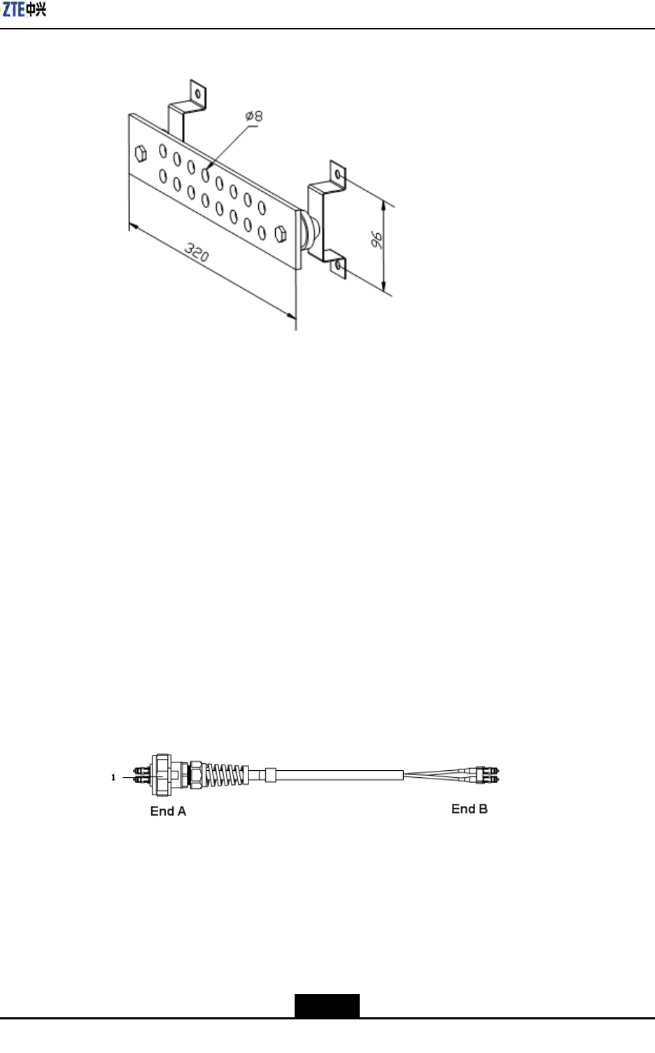
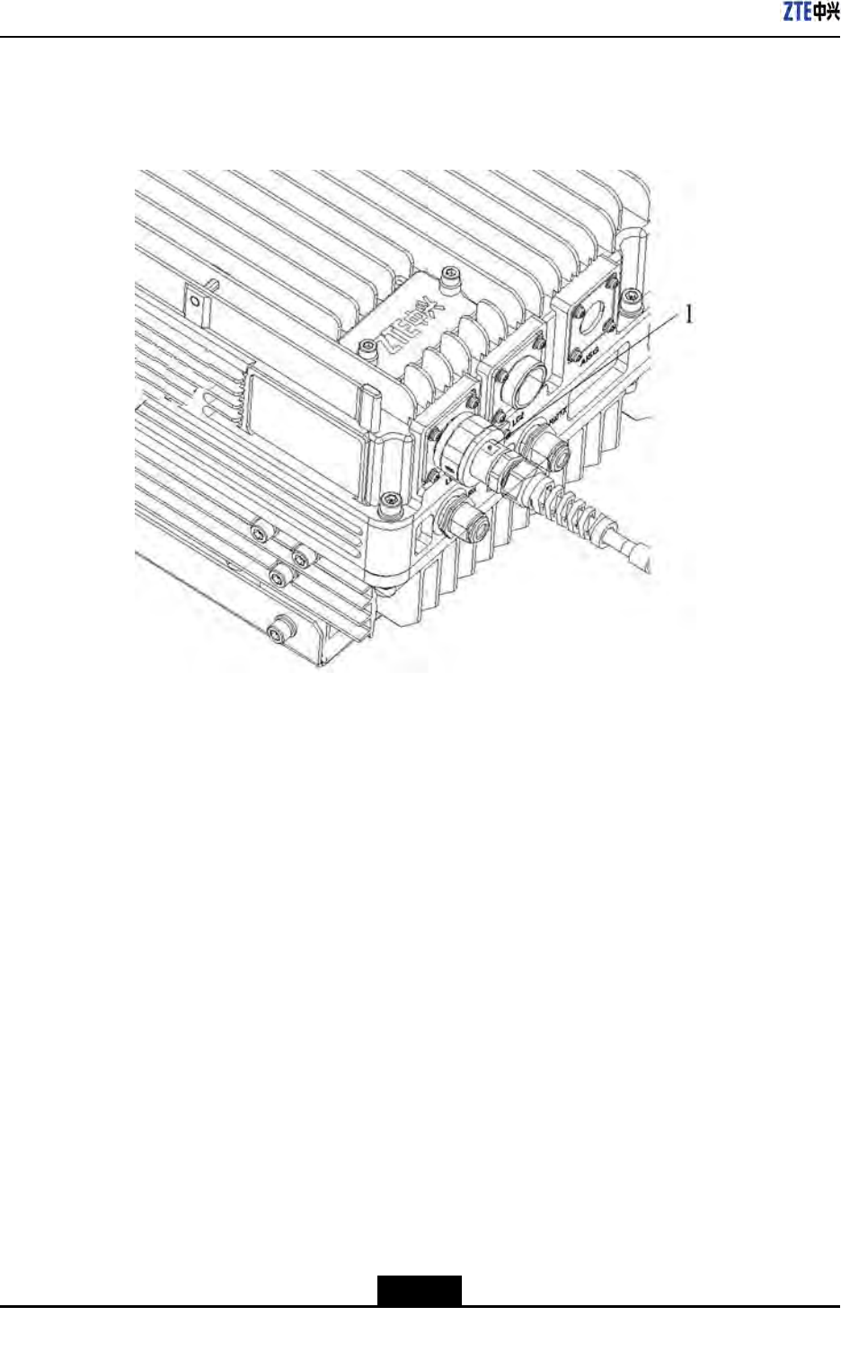
4.6InstallingFiberbetweenBBUandRRU
Prerequisites
TheZXSDRR8860cabinetmustbeinstalledandxedsuccessfully.
Context
Figure4-11showsberconnectionbetweenZXSDRR8860andBBU.
Figure4-11FiberConnectionbetweenZXSDRR8860andBBU
1.OutdoorSealComponent
WhileconnectingaBBUtoZXSDRR8860,makesurethatthebasebandRFberinterface
(LC1/2)oftheZXSDRR8860isconnectedtotheopticalinterfaceconnectoroftheBBU.
Steps
1.Attachlabelsatbothendsoftheber.
4-9
SJ-20100722143906-002|02/20/2011(R1.3)ZTEProprietaryandCondential
ZXSDRR8860InstallationManual
2.AdjustthesideofEndAwiththecolormarkandinserttheZXSDRR8860ber
interface,andscrewdownthenuts,asshowninFigure4-12
Figure4-12OpticalFiberInstallation
1.Colormark
3.ConnectEndAofthebertothebasebandRFberinterface(LC1/2)oftheZXSDR
R8860.
4.ConnectEndBoftheber,whichisaDLCconnector,totheBBUopticalconnector.
5.ScrewdowntheoutdoorsealcomponentatEndAforwaterproong.
6.Performingoutdoorconnectorwaterproofprocessing,referto4.3Specicationsof
1+3+3WaterproofProcessingwithPlasterandT ape.
–EndofSteps–
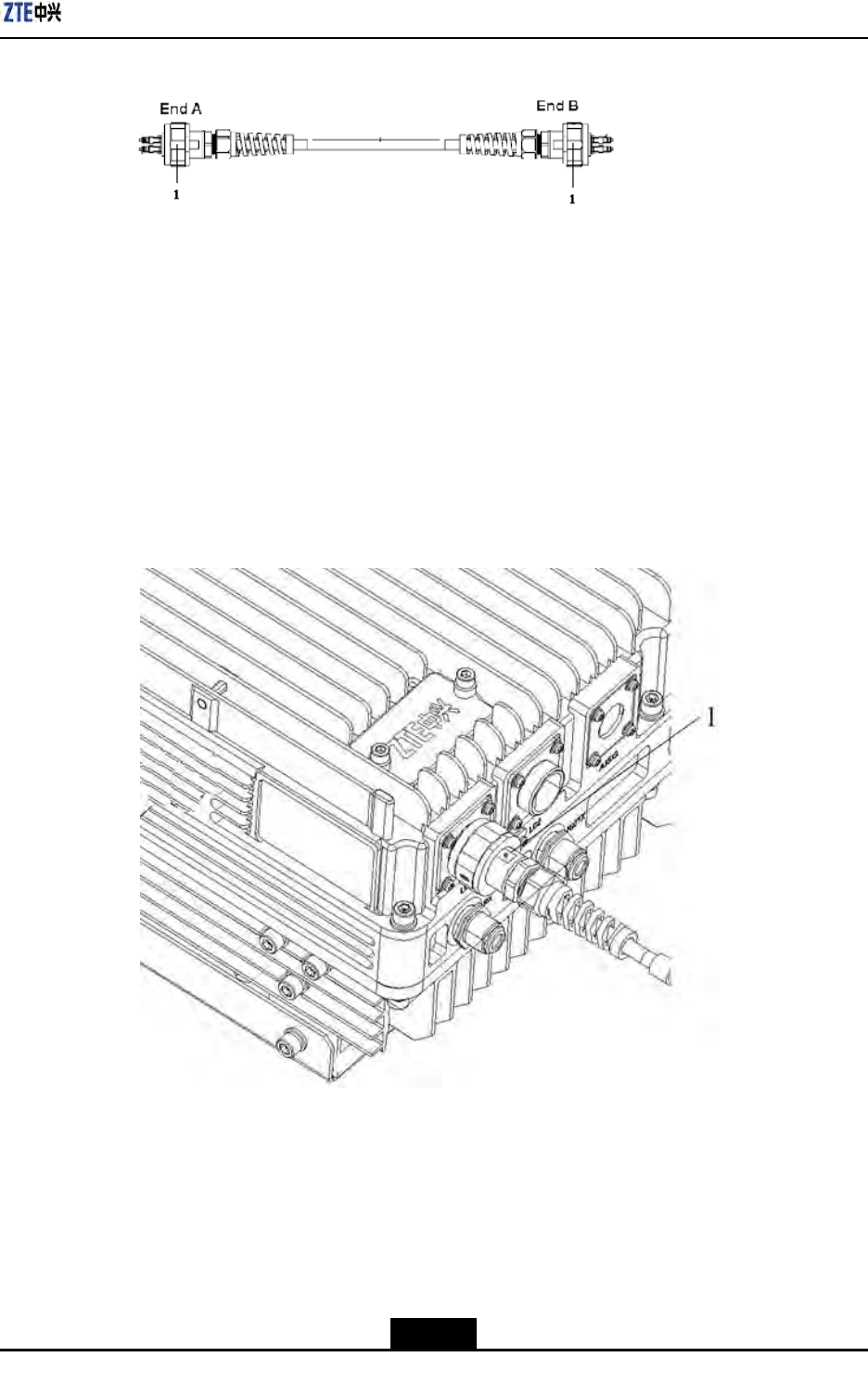
4.7InstallingFiberbetweenRRUandRRU
Prerequisites
ThecascadingZXSDRR8860cabinetsmustbeinstalledandxedsuccessfully.
Context
Figure4-13showsberconnectionbetweenZXSDRR8860s.
4-10
SJ-20100722143906-002|02/20/2011(R1.3)ZTEProprietaryandCondential
Chapter4ExternalCableInstallation
Figure4-13FiberConnectionbetweenZXSDRR8860s
1.OutdoorSealComponent
WhileinterconnectingtheZXSDRR8860s,makesurethatthetwobasebandRFber
interfaces(LC1/2)oftheZXSDRR8860areconnected.
Steps
1.Attachlabelsatbothendsoftheopticalber.
2.AdjustthesideofEndAwiththecolormarkandinserttheZXSDRR8860ber
interface,andscrewdownthenuts,asshowninFigure4-14.
Figure4-14OpticalFiberInstallation
1.Colormark
3.ConnectEndAoftheopticalbertothebasebandRFberinterface(LC1/2)ofthe
ZXSDRR8860.
4.ConnectEndBoftheopticalbertotheotherbasebandRFberinterface(LC1/2)of
theZXSDRR8860.
5.ScrewdowntheoutdoorsealcomponentatEndAforwaterproong.
4-11
SJ-20100722143906-002|02/20/2011(R1.3)ZTEProprietaryandCondential
ZXSDRR8860InstallationManual
6.Performingoutdoorconnectorwaterproofprocessing,referto4.3Specicationsof
1+3+3WaterproofProcessingwithPlasterandT ape.
–EndofSteps–
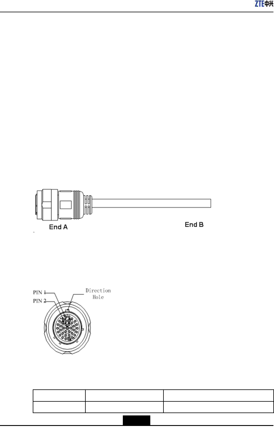
4.8InstallingEnvironmentMonitoringCable
Prerequisites
TheZXSDRR8860cabinetmustbeinstalledandxedsuccessfully.
Context
Theenvironmentmonitoringcableprovidesa485interface,usedforZXSDRR8860
environmentmonitoring.Inaddition,thecablealsoprovidesfourextensionaccessesfor
externaldrycontactmonitoring.
EndAisthe37PINconnector,andEndBismadebyon-siteengineering.Thetotallength
is3m.Figure4-15showstheappearanceofenvironmentmonitoringcable.
Figure4-15EnvironmentMonitoringCable
Theconnector,connectingtheenvironmentmonitoringcabletotheZXSDRR8860,
adopts37–coreaviationjack.TheconnectoraccordswiththeGJB599specication.The
connectorappearanceisasshowninFigure4-16
Figure4-16AviationJackAppearance
Table4-4describestheconnectorpins.
Table4-4CablePinDescription
PinCore-CableColorSignalDescription
15/16Whiteandblue/blueDrycontact4-/+
4-12
SJ-20100722143906-002|02/20/2011(R1.3)ZTEProprietaryandCondential
Chapter4ExternalCableInstallation
PinCore-CableColorSignalDescription
17/18Whiteandorange/orangeDrycontact3-/+
19/20Whiteandgreen/greenDrycontact2-/+
21/22Whiteandbrown/brownDrycontact1-/+
23/24Redandblue/blueRS485receive
25/26Redandorange/orangeRS485transmit
Steps
1.ConnectEndAtotheMONinterfacelocatedatthebottomofZXSDRR8860.
2.ConnectEndBwithexternalmonitoringdevicesordrycontacts.
3.AttachthelabelatEndB.
4.Performingoutdoorconnectorwaterproofprocessing,referto4.3Specicationsof
1+3+3WaterproofProcessingwithPlasterandT ape.
–EndofSteps–
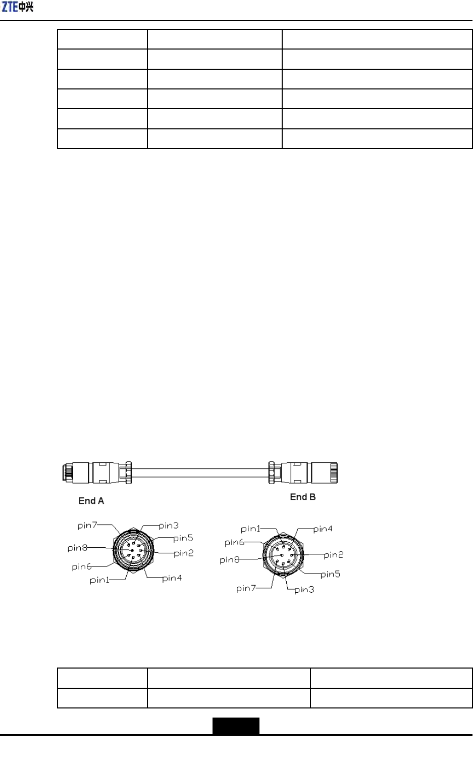
4.9InstallingAISGControlCable
Context
TheAISGcontrolcableisusedforcontroloftheelectricaladjustmentantenna.
Figure4-17showsthestructureoftheAISGcontrolcable.
Figure4-17AISGControlCableStructure
Table4-5describestheserialNo.meaningofAISGcontrolcable.
Table4-5AISGControlCableDescription
SerialNo.NameMeaning
1TRX_ANT_485_+RS485+
4-13
SJ-20100722143906-002|02/20/2011(R1.3)ZTEProprietaryandCondential
ZXSDRR8860InstallationManual
SerialNo.NameMeaning
2TRX_ANT_485_-RS485-
3,4TRX_ANT_28V28V
5,6TRX_ANT_28VGND28VGND
7,8NCNull
Steps
1.ConnectEndAtotheZXSDRR8860debugginginterface(AISG)andscrewdownthe
bolt;
2.ConnectEndBtothecontrolinterfaceofelectricaladjustmentantennaandscrew
downthebolt.
3.Performingoutdoorconnectorwaterproofprocessing,referto4.3Specicationsof
1+3+3WaterproofProcessingwithPlasterandT ape.
–EndofSteps–
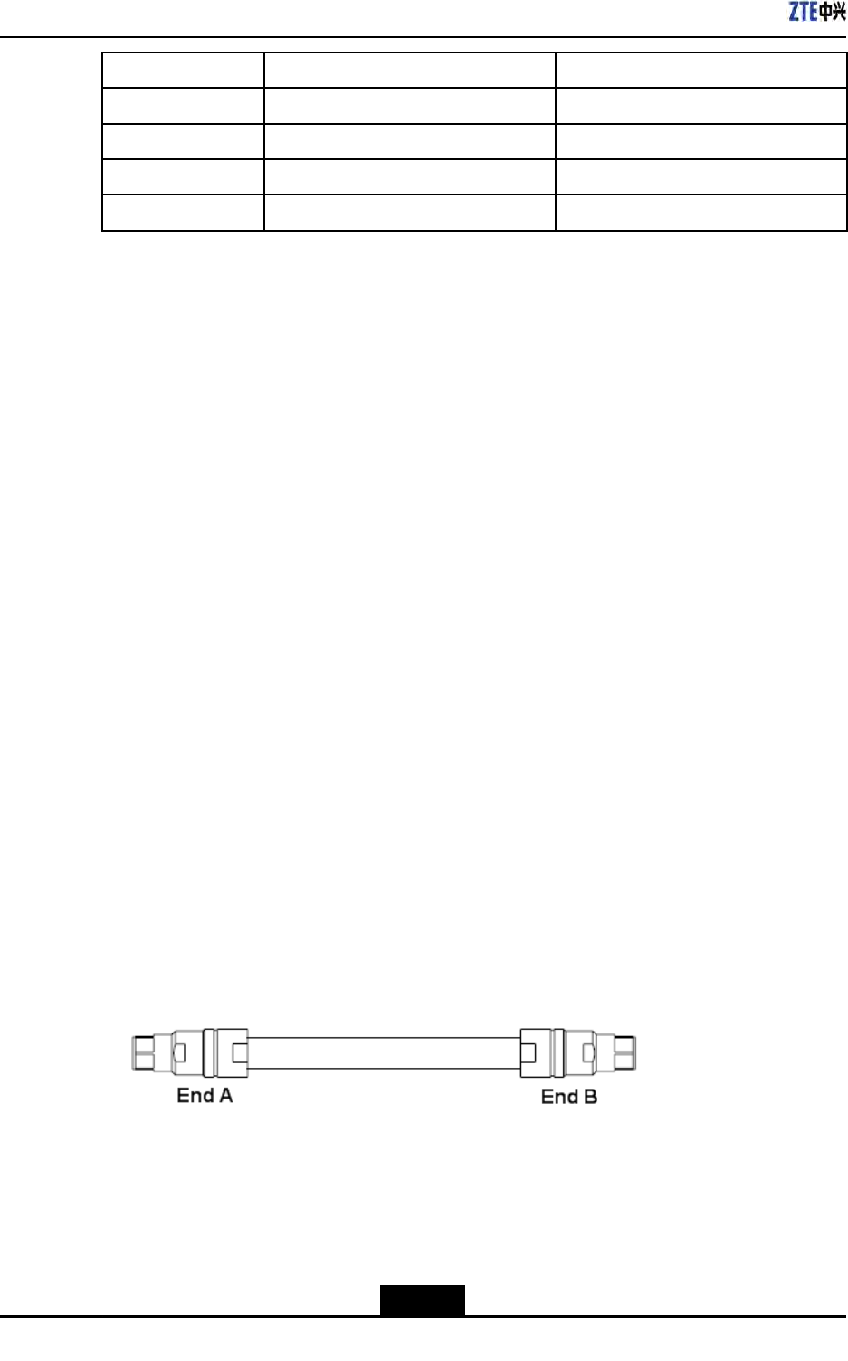
4.10InstallingFrequencyPointExtensionCable
Prerequisites
ThetwoZXSDRR8860cabinetstobecombinedmustbeinstalledandxedsuccessfully.
Context
Afterthecombinationofcabinets,theZXSDRR8860cansupport8carriersectorsatmost.
ThetwoZXSDRR8860cabinetsareconnectedthroughtheirconnectinginterfacessuchas
RXinandRXoutbytwofrequencypointextensioncables.Figure4-18showsthestructure
ofthefrequencypointcable.EndAandEndBareNconnectors(male).
The2M1/2″jumperisoftenusedforthefrequencypointextensioncable.Itmaybe
preparedonsiteifnecessary.
Figure4-18FrequencyPointExtensionCable
Steps
1.ConnectEndAofthefrequencypointextensioncabletothefrequencypointextension
interfaceRXINofoneZXSDRR8860;
4-14
SJ-20100722143906-002|02/20/2011(R1.3)ZTEProprietaryandCondential
Chapter4ExternalCableInstallation
2.ConnectEndBtoRXoutoftheotherZXSDRR8860;
3.ConnecttheremainingRXin/RXoutinterfacesofthetwocombinedcabinetswiththe
otherfrequencypointextensioncable.
4.Performingoutdoorconnectorwaterproofprocessing,referto4.3Specicationsof
1+3+3WaterproofProcessingwithPlasterandT ape.
–EndofSteps–
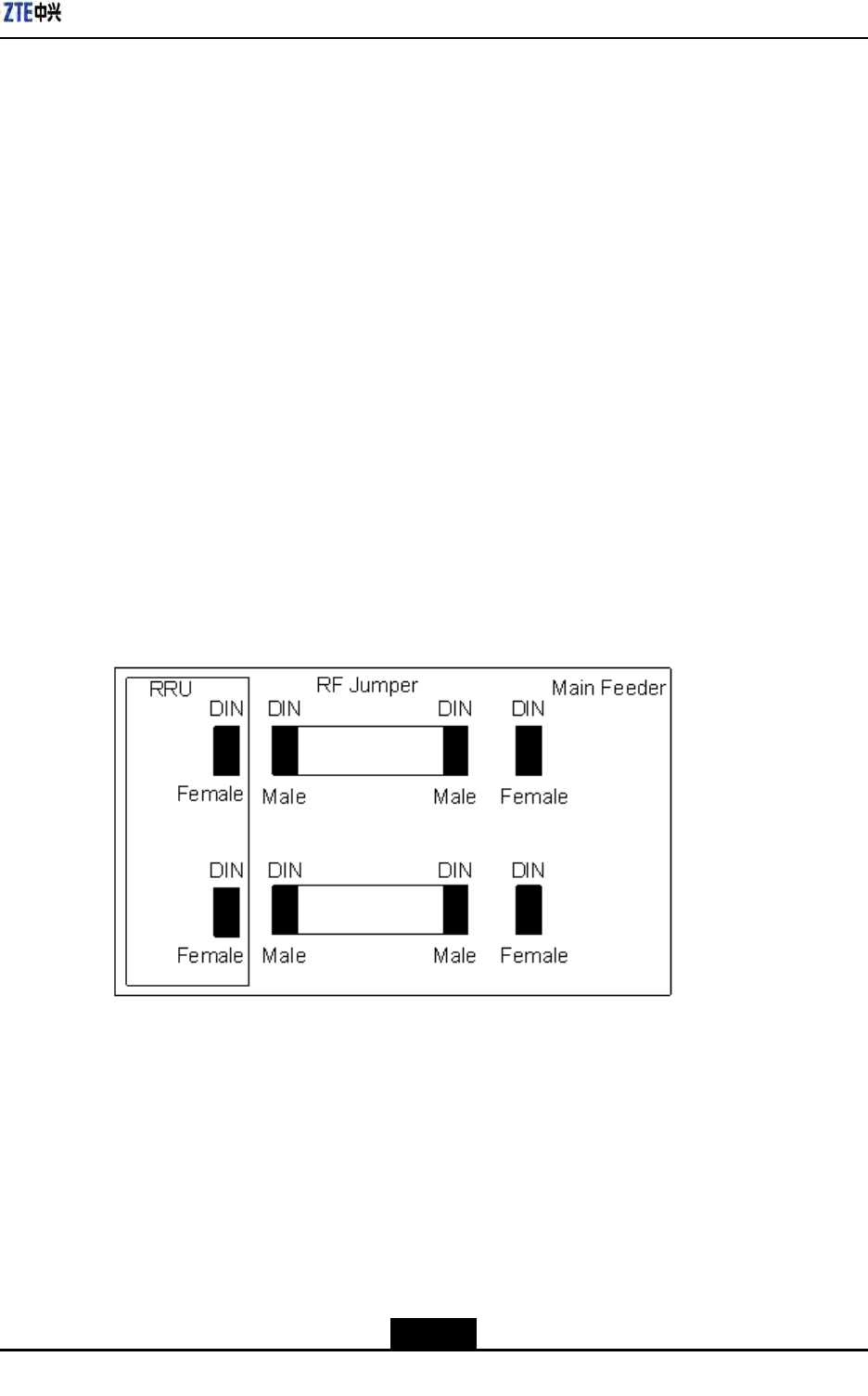
4.11InstallingJumper
Context
OneendofRFjumperconnectswiththemainfeederandtheotherendconnectswiththe
antennafeederinterfaceofZXSDRR8860cabinet.BeforeinstallingtheRFjumper,the
mainfeederisinstalled.
TheRFjumperadoptsthe1/2″jumperwitha2mlength.Thejumpercanalsobeself-made
accordingtotheon-sitecondition.
TheinstallationpositionofRFjumperisasshowninFigure4-19.
Figure4-19RFJumperInstallation
PerformthefollowingstepstoinstalltheRFjumper.
Steps
1.ConnecttheDINconnector(male)ofRFjumperwiththeDINconnector(female)of
mainfeeder.
2.ConnecttheDINconnector(male)ofRFjumperwiththeDINconnector(female)of
ZXSDRR8860cabinet.
3.SealtheconnectorswithwaterproofadhesivetapesandPVCtapes.
4-15
SJ-20100722143906-002|02/20/2011(R1.3)ZTEProprietaryandCondential

ZXSDRR8860InstallationManual
4.Performingoutdoorconnectorwaterproofprocessing,referto4.3Specicationsof
1+3+3WaterproofProcessingwithPlasterandT ape.
–EndofSteps–
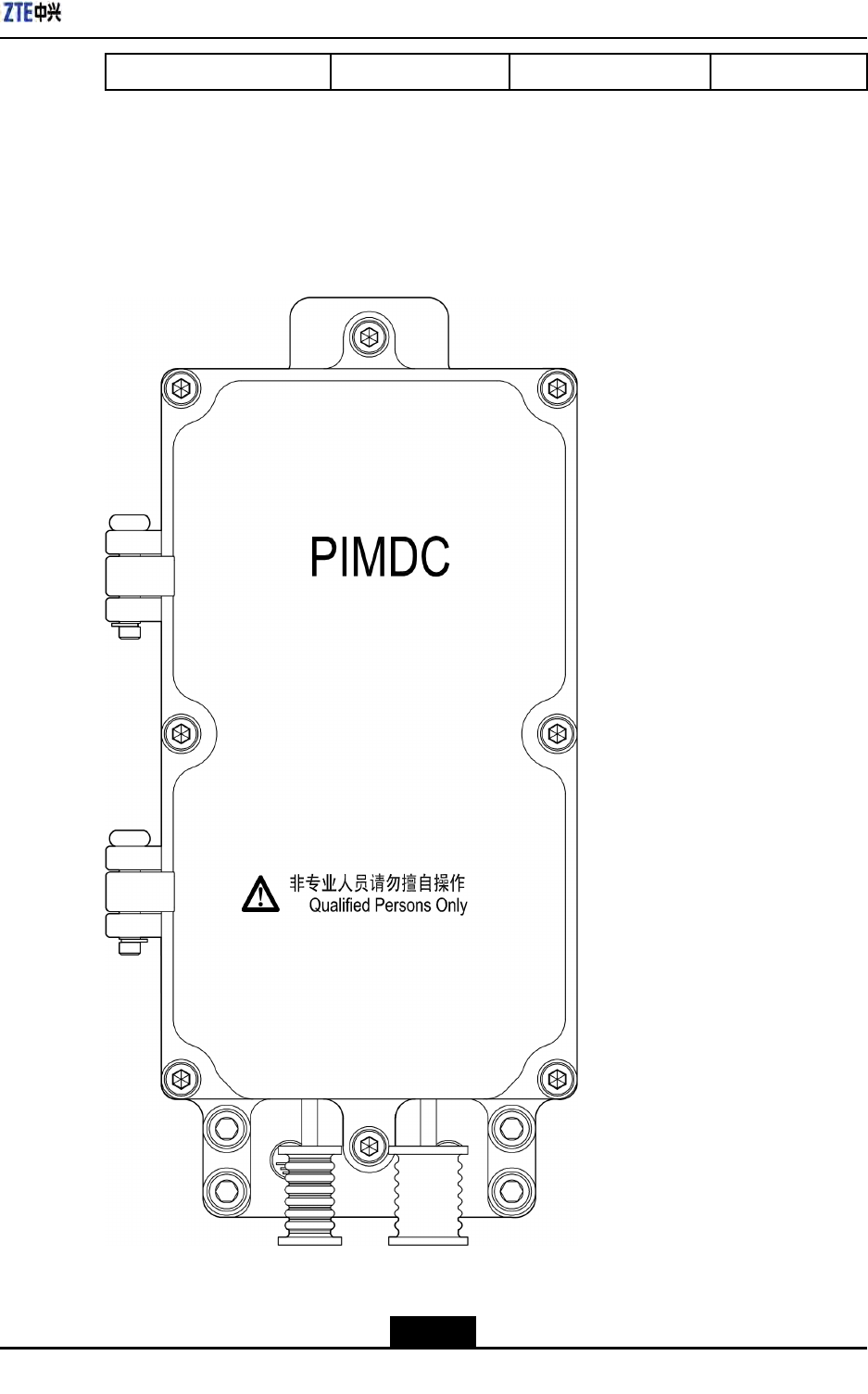
4.12InstallingPIMDC
4.12.1PIMDCechnicalIndices
TheoutdoorDClightningbox(PIMDC)isusedforsurgeprotectionofZXSDRR8860.The
followingdescribesitscharacters:
lBreaksawayfromthepowersupplysystempermanentlytoavoidshortcircuitin
electricnetworkwhenmalfunctionedorfailed.
lAdoptsspecialvoltage-sensitivemoduleswithovercurrentandoverheatprotection,
highsurgecurrentandlowresidualvoltage.
lEquipsremotesignallingalarminterface.(Theremotedrycontactisnormallyclosed
atnormalcondition.Whensomepartsfailedorpoweriscutedoff,theremote
signallingdrycontactturnstobenormallyopenfromnormallyclosed.)
lTheenclosureismadeofaluminumdie-castingmetalanditsprotectiondegree
reachesthedemandofIP55.Itcanbeinstalledoutdoorforlongtermuseandhas
goodameretardance.
EngineeringTechnicalIndices
Table4-6describestheengineeringtechnicalindicesofPIMDC.
Table4-6EngineeringTechnicalIndicesofPIMDC
NominalOperatingVolt-
ageUnDC-48VConnectionTypeInSeries
Max.ContinuousOperat-
ingVoltageUcDC-75VProtectionModel
Differentialand
CommonMode
NominalDischargeCur-
rentIn8/20μs20kAResponseTime≤25ns
Max.DischargeCurrent
Imax8/20μs40kA
LeadAreaClampedby
thePowerConnecting
Terminal2.5mm210mm2
ProtectionLevelUpIn≤180V
LeadAreaClampedby
DryContactTerminal0.15mm21.3mm2
RatedLoadCurrentIL18AOperatingTemperature-40℃+70℃
LoadSideImpactCapacity
8/20μs8kAOperatingHumidity109525oC
Enclosure
Die-castingAlu-
minumSprayPaintAltitude≤3000m
4-16
SJ-20100722143906-002|02/20/2011(R1.3)ZTEProprietaryandCondential
ZXSDRR8860InstallationManual
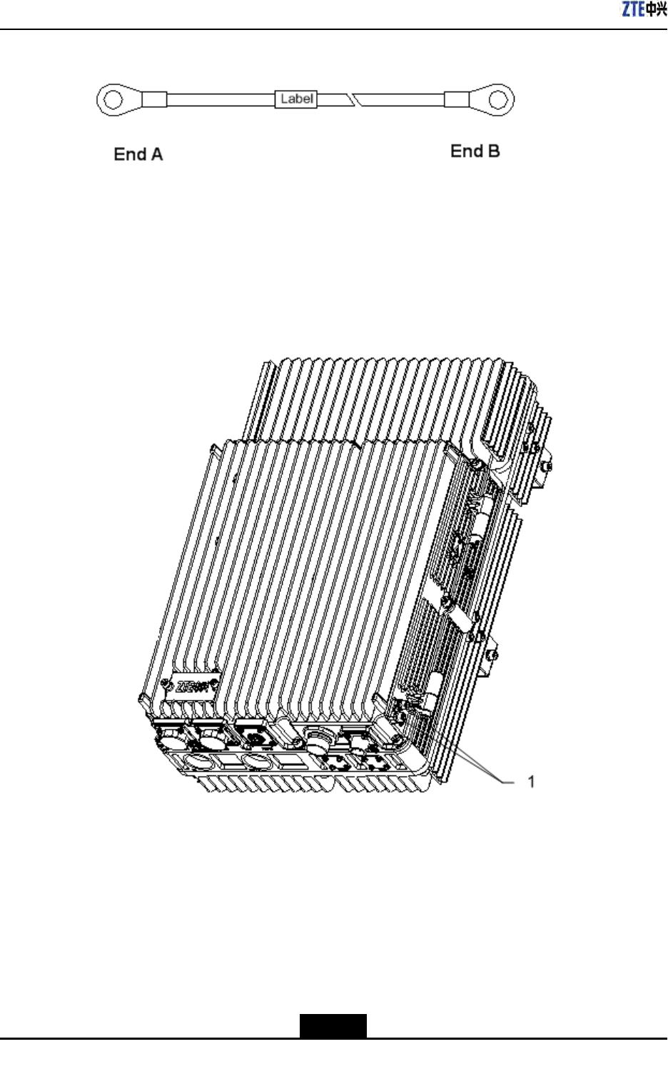
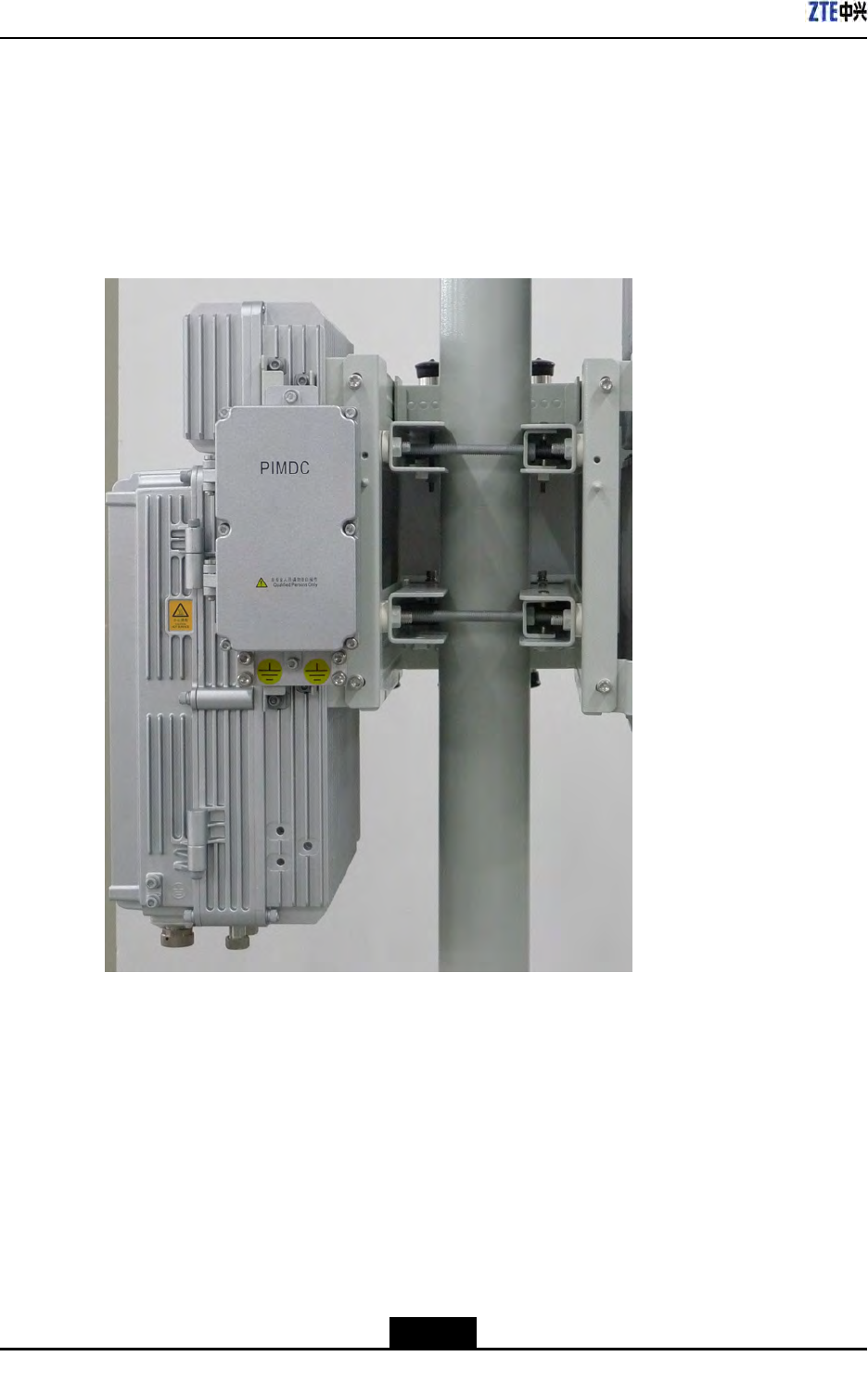
4.12.3PIMDCInstallationDescription
Inatallation
FastenthePIMDCononesideoftheZXSDRR8860mountingbracketusingtwoscrews,
asshowninFigure4-21.
Figure4-21InstallingPIMDC
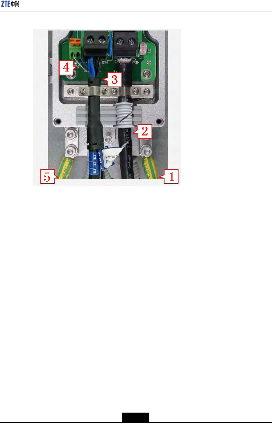
ConnectingCables
OpenPIMDCcabinet,ConnectthePIMDCcables,asshowninFigure4-22.
4-18
SJ-20100722143906-002|02/20/2011(R1.3)ZTEProprietaryandCondential
Chapter4ExternalCableInstallation
Figure4-22PIMDCConnection
1.Groundcablebetweenthe
PIMDCandtheRRU
2.Inputpowercableofthe
PIMDC
3.Inputpowercableofthe
RRU
4.Drycontactcable
5.GroundcableofthePIMDC
1.ConnectgroundcableofthePIMDC,thegroundcableofthePIMDCisshowninFigure
4-22"5".
2.ConnecttheA-endtothe"InputSide"ofthePIMDCthroughthewaterproofplastic
ring:connectthebluecableto-48Vportandconnecttheblackcableto-48VRTNport
(theinputpowercableofthePIMDCisshowninFigure4-22"2".)
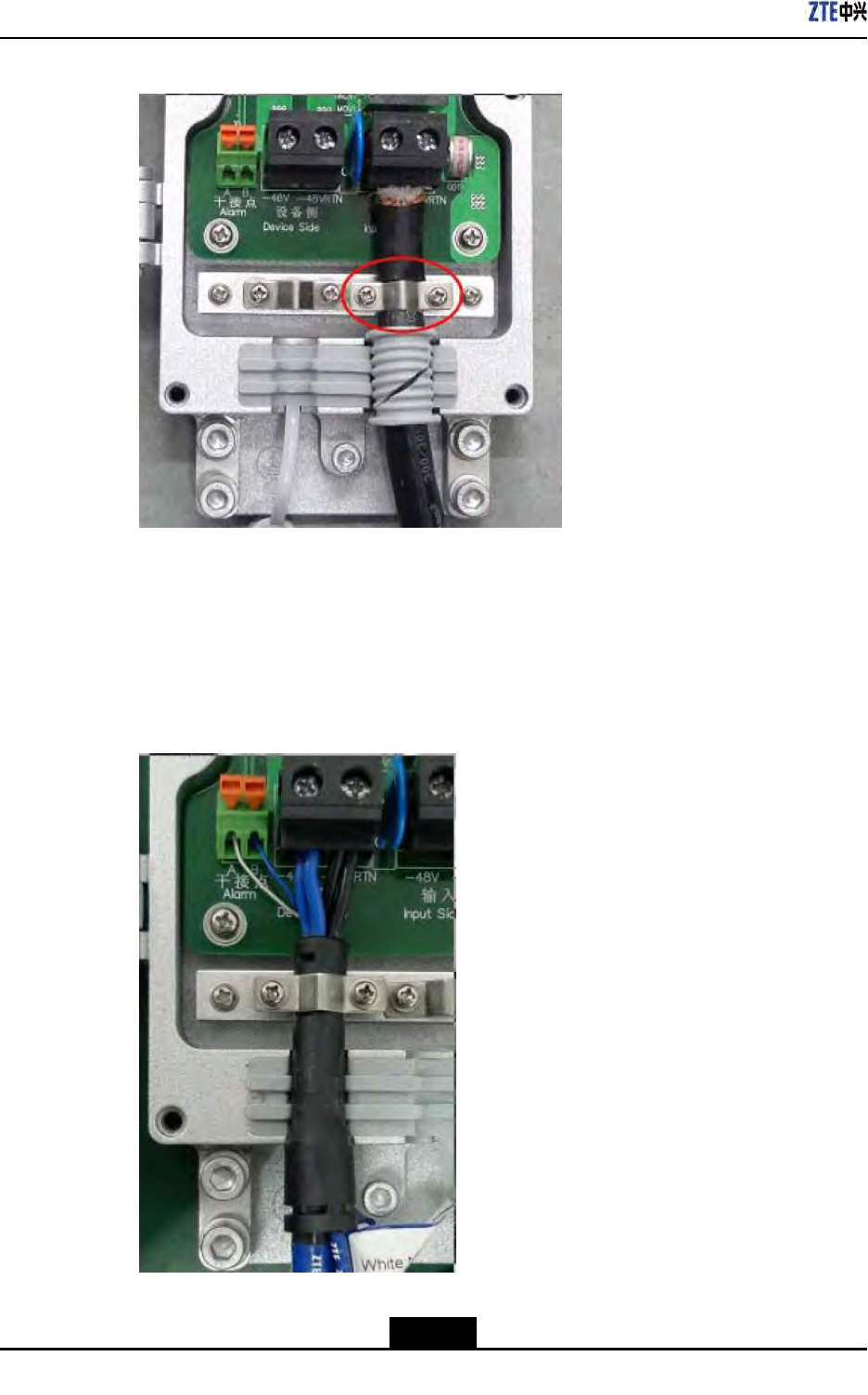
3.Fastenthepowercablewithalatch.Note:Thislatchshouldstaycontactwiththe
shieldedlayerofthepowercable,asshowninFigure4-23.
4-19
SJ-20100722143906-002|02/20/2011(R1.3)ZTEProprietaryandCondential
ZXSDRR8860InstallationManual
Figure4-23ConnectPowerInputCable
4.ConnecttheA-endoftheoutputpowercable(asshowninFigure4-22"3".)tothe
devicesideonthePIMDC:connectthebluecableto-48Vportandconnecttheblack
cableto-48VRTNport,asshowninFigure4-24.
5.Connectthewhiteandbluedrycontactcables(asshowninFigure4-22"4".)tothe
"Alarm"ports,asshowninFigure4-24.
Figure4-24ConnectingOutputPowerCableandDryContactCables
4-20
SJ-20100722143906-002|02/20/2011(R1.3)ZTEProprietaryandCondential


ZXSDRR8860InstallationManual
Thispageintentionallyleftblank.
4-22
SJ-20100722143906-002|02/20/2011(R1.3)ZTEProprietaryandCondential

Chapter5
MainAntennaFeederSystem
Installation
TableofContents
MainAntennaFeederSystemStructure.....................................................................5-1
MainAntennaFeederSystemInstallationPreparation...............................................5-7
MainAntennaFeederSystemInstallationFlow..........................................................5-8
AntennaInstallation....................................................................................................5-9
FeederInstallation....................................................................................................5-15
InstallingFeederHermetic-window...........................................................................5-25
FeederIndoorIngoing..............................................................................................5-27
PerformingAntennaFeederSystemTest.................................................................5-31
PerformingOutdoor-ConnectorWaterproofProcessing............................................5-32
PerformingFeederHermetic-windowWaterproofProcessing...................................5-36
ChassisJumperInstallationDescription...................................................................5-39
VSWRTest...............................................................................................................5-40
5.1MainAntennaFeederSystemStructure
ThetypicalcongurationsofZXSDRR8860mainantennafeedersystemdescribedbelow
includes:
lZXSDRR8860conguredwithcommonantenna
lZXSDRR8860conguredwithcommonantennaandAISGdualtoweramplier
lZXSDRR8860conguredwithelectricallytunedantenna(1)
lZXSDRR8860conguredwithelectricallytunedantenna(2)
lZXSDRR8860conguredwithelectricallytunedantenna,AISGdualtoweramplier
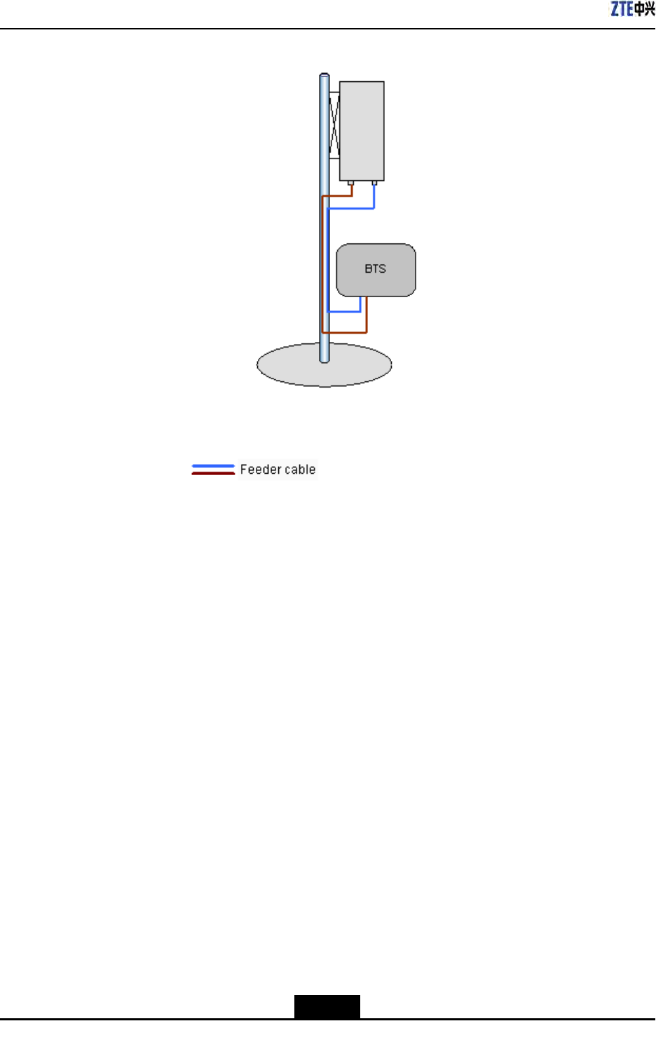
ZXSDRR8860conguredwithcommonantenna
Inthisconguration,generallyZXSDRR8860installationpositionisnearantennaand
theyareallinstalledonthebuildingtop.ZXSDRR8860isconnectedtotheantennaby
1/2″feederdirectly,occasionally5/4″or7/8″feederisadopted,asshowninFigure5-1.
5-1
SJ-20100722143906-002|02/20/2011(R1.3)ZTEProprietaryandCondential
ZXSDRR8860InstallationManual
Figure5-1ZXSDRR8860ConguredwithCommonAntenna
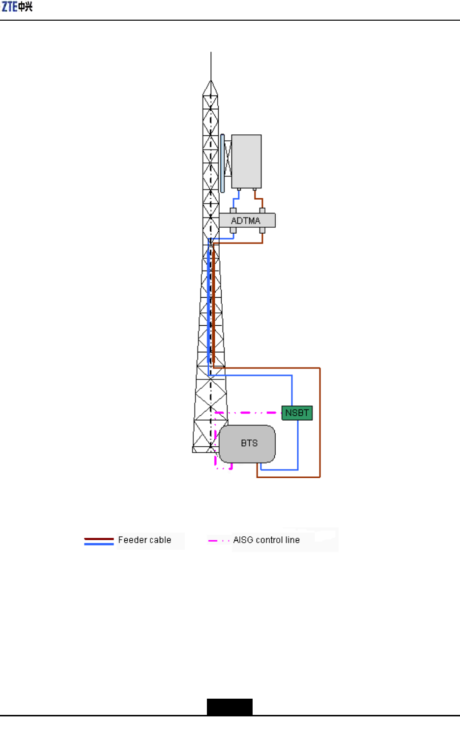
ZXSDRR8860conguredwithcommonantennaandAISGdualtoweramplier
Inthisconguration,generallyZXSDRR8860isinstalledonthetower.ZXSDRR8860is
connectedtotheantennaby5/4″or7/8″feeder,asshowninFigure5-2.
5-2
SJ-20100722143906-002|02/20/2011(R1.3)ZTEProprietaryandCondential
Chapter5MainAntennaFeederSystemInstallation
Figure5-2ZXSDRR8860ConguredwithCommonAntenna,AISGDualTowerAmplier
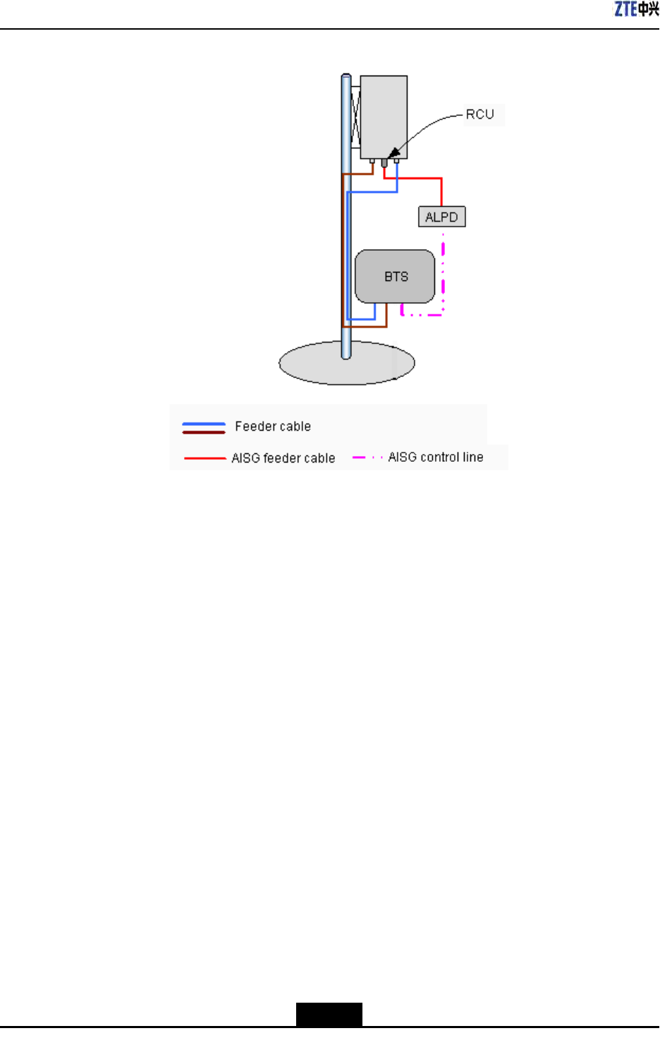
ZXSDRR8860conguredwithelectricallytunedantenna(1)
Inthisconguration,generallyZXSDRR8860installedneartheantennaonthebuilding
top.ZXSDRR8860isconnectedtotheantennaby1/2″feederdirectly,occasionally5/4″or
7/8″feederisadopted,asshowninFigure5-3.
5-3
SJ-20100722143906-002|02/20/2011(R1.3)ZTEProprietaryandCondential
ZXSDRR8860InstallationManual
Figure5-3ZXSDRR8860ConguredwithElectricallyTunedAntenna(1)
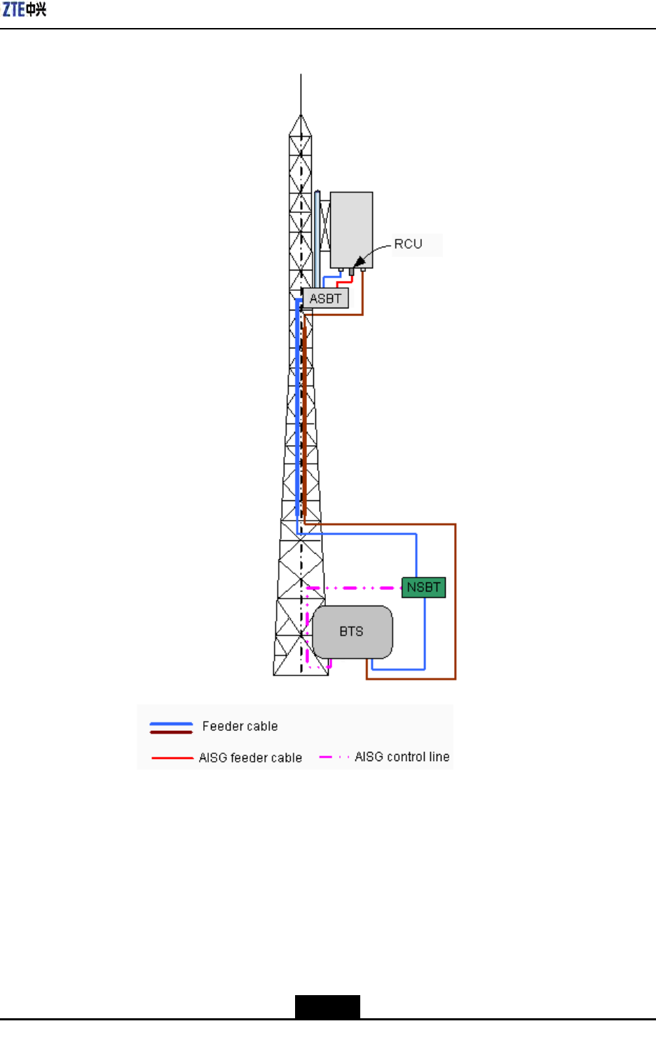
ZXSDRR8860conguredwithelectricallytunedantenna(2)
Inthisconguration,generallyZXSDRR8860isinstallednearthetopofthetower.ZXSDR
R8860isconnectedtotheantennaby5/4″or7/8″feederisadopted,asshowninFigure
5-4.
5-4
SJ-20100722143906-002|02/20/2011(R1.3)ZTEProprietaryandCondential
Chapter5MainAntennaFeederSystemInstallation
Figure5-4ZXSDRR8860ConguredwithElectricallyTunedAntenna(2)
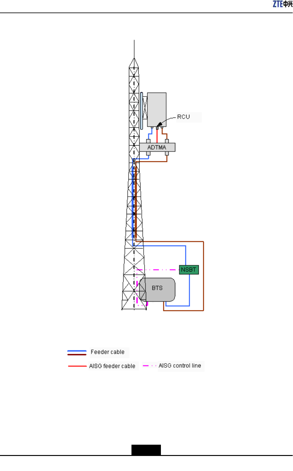
ZXSDRR8860conguredwithelectricallytunedantenna,AISGdualtoweramplier
Inthisconguration,generallyZXSDRR8860isinstallednearthetopofthetower.ZXSDR
R8860isconnectedtotheantennaby5/4″or7/8″feederisadopted,asshowninFigure
5-5.
5-5
SJ-20100722143906-002|02/20/2011(R1.3)ZTEProprietaryandCondential
ZXSDRR8860InstallationManual
Figure5-5ZXSDRR8860ConguredwithElectricallyTunedAntennaandAISGDual
TowerAmplier
5-6
SJ-20100722143906-002|02/20/2011(R1.3)ZTEProprietaryandCondential
Chapter5MainAntennaFeederSystemInstallation
5.2MainAntennaFeederSystemInstallation
Preparation
ProperantennainstallationisveryimportanttoZXSDRR8860systemreliableoperation.
Beforeinstallation,makesurethatinstallationstaffisqualiedandthefollowing
requirementsaresatised.
PersonnelRequirement
Normally,supervisorsareinchargeofdirectionandsupervision,whereasinstallation
personnelcarryouttheinstallation.
lInstallationSupervisor
Therequirementsfortheinstallationsupervisorareasfollows:
àFamiliarwithallmaterials,toolsandoperationmethods.
àInchargeofassigningdifferentworktotheproperemployeewhoisgoodatthe
operation,especiallywhileworkingontheirontower.
Note:
Safetyisthemostimportantconsiderationwhenassigningwork.
lInstallationPersonnel
Therequirementsfortheinstallationpersonnelareasfollows:
àInstallationemployeesarerequiredtoinstallantennasystemskillfullyunderthe
directionofsupervisor.
àEmployeesontowermustbequaliedandingoodphysicalstate.
àInstallationafterdrinkingisforbidden.
EnvironmentRequirement
Payattentiontofollowingitemsandcheckwhethertheseitemsaccordwithrequirements
inengineeringdesign.
lLightningprotectionandgrounding
ZXSDRR8860isusuallylocatedoutdoors.Thegroundingstakeandoutdoor
lightning-protectinggroundingcablesareinstalledbytheoperator,andthesupervisor
shouldconrmlightning-protectinggroundingcablesareinstalledproperly.
lPoleandsupportingrack
Accomplishinstallationofantennasupportingrackandpoleaccordingtoproject
designrequirement.Thestabilityofthesupportingrackandpoleshouldbein
accordancewiththedesignrequirement.
5-7
SJ-20100722143906-002|02/20/2011(R1.3)ZTEProprietaryandCondential

ZXSDRR8860InstallationManual
lFeederlayout
Fieldengineerneedtoconsultwithoperatorengineers,anddeterminetherouteof
feeder.
lElectronicpowerenvironment
lZXSDRR8860antennaandfeedersystemcannotbeinstalledtooneartopublic
electricpowercables.
SafetyPrecautions
Ensurethefollowingprecautionsbeforeantennainstallation:
lTakenecessarymeasuresforpersonalandequipmentsafety.
lPersonnelundertowermustwearsafetyhelmets.
lPersonnelontowermustwearsafetybelt.
lNeverclimbtowerwithlooseclothesandwet/slipperyshoes.
lDuringactiveantennaadjustment,wearradiation-shieldingclothingandturnoffpower
ampliertoavoidradiationeffects.
lIfpossible,installinsunnyandwindlessdays.Installationisforbiddeninrain,strong
wind,thunderandlightning.
lMakecautionbrandinengineeringeldandkeeppasserbyawayfromengineering
eld,especiallykids.
lWhenworkingontower,putunusedtoolsinatoolbagandpreventthemfromdropping
downfromtowertohurtpeople.
ToolsRequirement
Thefollowingtoolsarerequiredformainantennafeedersysteminstallation:
lMeasuretools
Compass,multimeter,anglemeter,andtapemeasure
lSpecialtools
Specialtoolsandinstrumentsformainfeederconnectormakingandtest
lRegulartools
Adjustablewrench,sharp-nosepliers,diagonalpliers,hacksaw(withseveralsaw
blades)
lProtectiontools
Safetyhelmet,safetybelt,safetyrope,gloves,radiation-shieldingclothes,multiple
powersocketandsealedcanvastoolbag
lOthertools
Toolsforlifting,e.g.Ladder
5.3MainAntennaFeederSystemInstallationFlow
Figure5-6showstheinstallationowofmainantennafeedersystem.
5-8
SJ-20100722143906-002|02/20/2011(R1.3)ZTEProprietaryandCondential
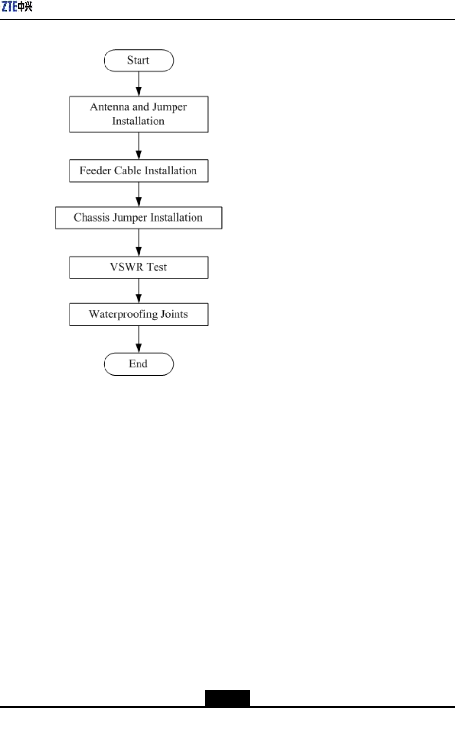
Chapter5MainAntennaFeederSystemInstallation
Figure5-6MainAntennaFeederSystemInstallationFlow
5.4AntennaInstallation
5.4.1AntennaInstallationTechnicalSpecifications
Theantennatechnicalspecicationsandtheirdescriptionisgivenbelow.
lAntennaheight
Theinstallationheightofantennaisdeterminedbynetworkplanningdesign.
lAntennaazimuth
Theazimuthoftheantennaisdeterminedbynetworkplanningdesign.
lAntennadowntilt
Thedowntiltangleoftheantennaisdeterminedbynetworkplanningdesign.Usually
thedowntiltangleis0°~10°
lAntennadirection
Antennadirectiondependsontheantennaazimuth.Iftwoantennasinonesector,
mustsharethesameazimuth.
5-9
SJ-20100722143906-002|02/20/2011(R1.3)ZTEProprietaryandCondential
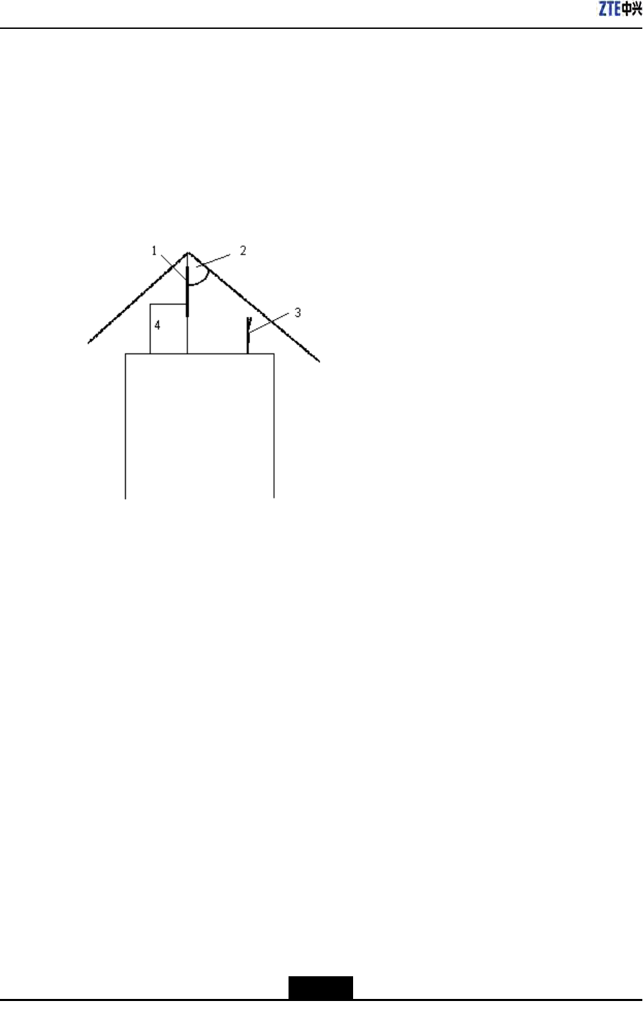
ZXSDRR8860InstallationManual
5.4.2AntennaInstallationPosition
Theantennainstallationpositionmustbeinaccordancewithprojectdesign.Ifthe
installationpositionneedsanymodication,theprojectsupervisormustnegotiatewith
operator'srepresentative.
Theantennainstallationpositionneedstotakecareforelightningprotectionasshownin
Figure5-7.
Figure5-7AntennaInstallationPosition
1.Lightningrod2.45°Lightningprotection
area
3.Antenna
4.Groundingcable
Followingarelightningprotectionrequirementstoinstallanantenna:
lTheantennashouldbeinstalledwithin45°coverageareaoflightningrod.
lIfthereisnospeciallightningprotectionarrangementliketheabove,installthe
lightningprotectionsystemontotheantennapole.
lMakesurethatthelightningrodiswellgrounded.
5.4.3InstallingDirectionalAntenna
Context
Thedirectionalantennainstallationprocedureisgivenbelow.
5-10
SJ-20100722143906-002|02/20/2011(R1.3)ZTEProprietaryandCondential
Chapter5MainAntennaFeederSystemInstallation
Note:
Thefollowingstepsdescribetheinstallationprocessasareferenceforinstallation
personnel.Duringtheon-siteinstallationprocess,pleasecarefullyreadtheinstallation
manualprovidedwiththeantenna,andcarryouttheinstallationaccordingtotheactual
condition.
Performthefollowingstepstoinstalladirectionalantenna:
Steps
1.Firstlyassemblefastener"C"ontotheupperandlowerendsofantennaasshownin
Figure5-8,thenmountfasteners"B"and"A"tocompletetheinitialinstallationofthe
directionalantenna.
Note:
lAllaccessoriesmustbeinstalledwithspringandplainwashers.
lUsuallytheantennafasteningaccessoriesandtheangleadjustmentdevice
accessorieshavealreadybeeninstalledontheantennabeforexingintothe
tower.
5-11
SJ-20100722143906-002|02/20/2011(R1.3)ZTEProprietaryandCondential
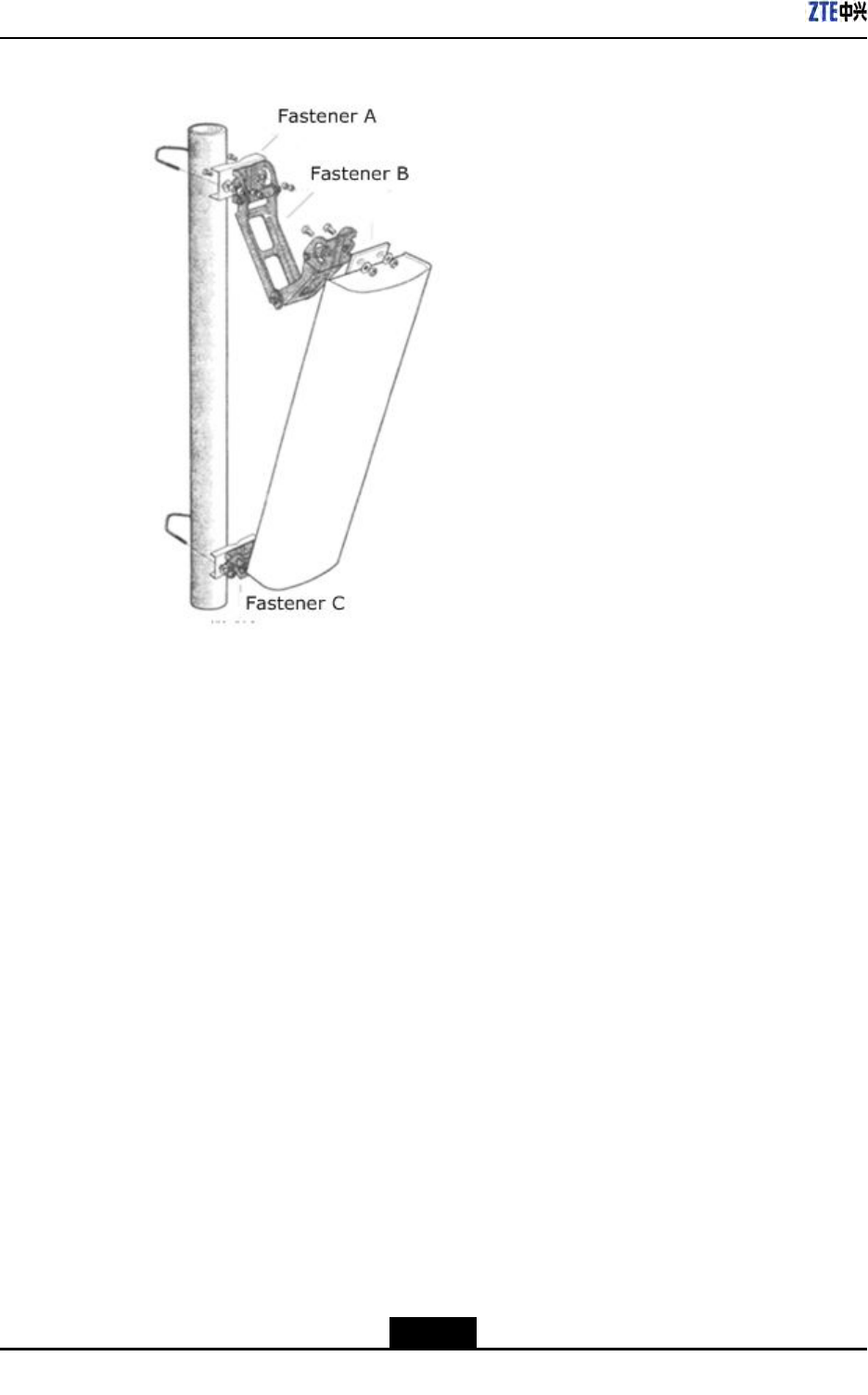
ZXSDRR8860InstallationManual
Figure5-8DirectionalAntennaInstallation
2.Attachtheantennaalongwithxturesontothepole.Donottightenthescrewstoo
tightlytoalloweasyadjustmentofthedirectionanddowntiltoftheantenna.However,
degreeoftightnessmustbehighenoughtoensurethattheantennadoesnotslide
downward.
3.Adjusttheantenna'sazimuth.
a.Determinetheazimuthoftheantennabyusingacompass,anddeterminethe
installationdirectionaccordingtotheengineeringdesigndrawing.
b.Turntheantennaslightlytoadjustit'sfacedirectionasshowninFigure5-8.Atthe
sametime,measurethedirectionoftheantennawithacompassuntiltheerror
comeswithintheengineeringdesignrequirements(generallynotmorethan5°).
c.Afteradjustingtheazimuthoftheantenna,tightenthefastener"A".
4.Adjusttheantenna'sdowntilt
a.Adjustthedowntiltofthemeasurementmetertoobtaintherequiredangle
accordingtotheengineeringdesign.
b.Turnthetopoftheantennaslightly,andlooseorfasttheantennaatitstop.Adjust
thedowntiltangleoftheantennatillthemeasurementmeter'sbubblecomestobe
centeredasshowninFigure5-9.
5-12
SJ-20100722143906-002|02/20/2011(R1.3)ZTEProprietaryandCondential
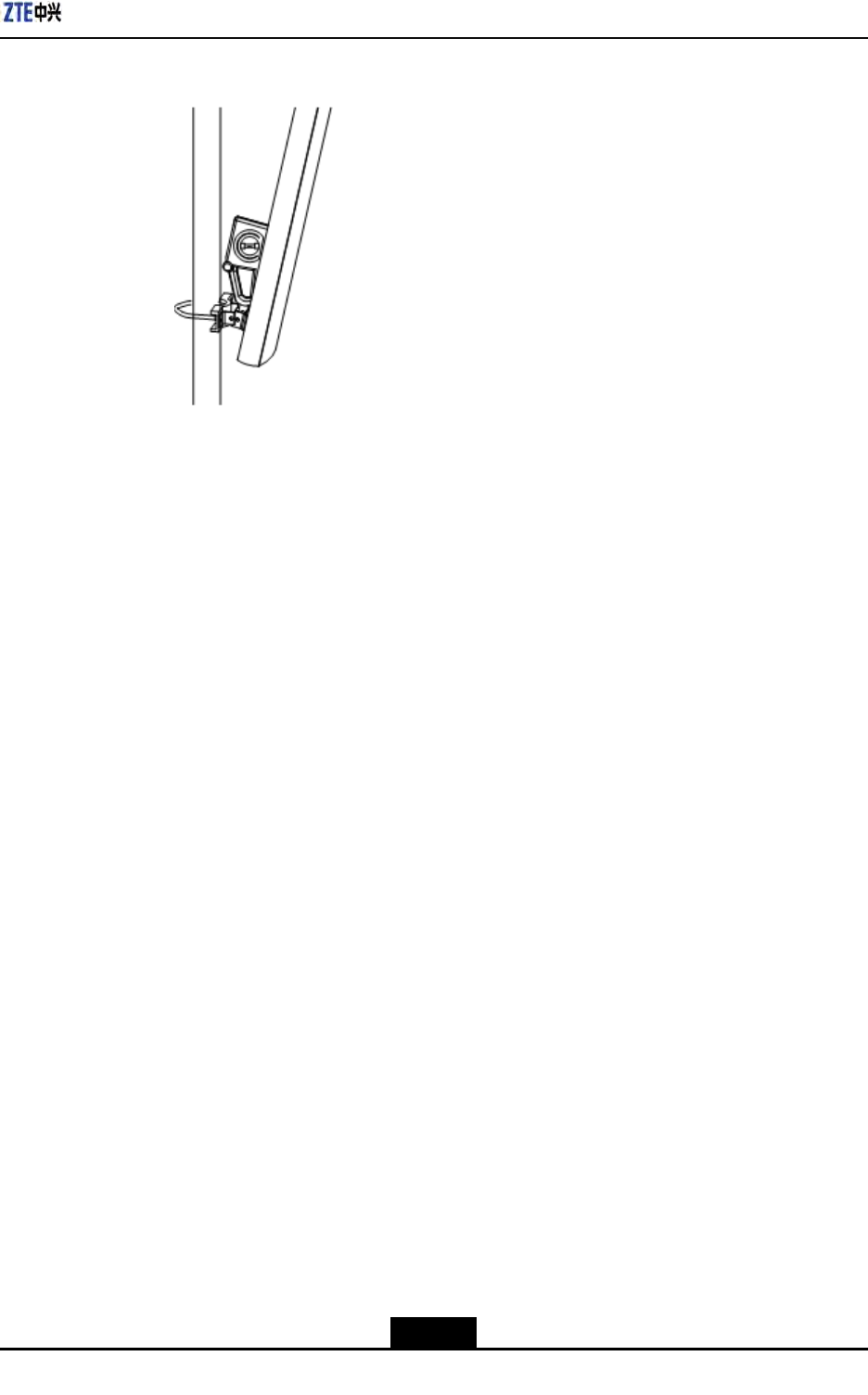
Chapter5MainAntennaFeederSystemInstallation
Figure5-9AntennaDowntiltAdjustment
c.Afteradjustingthedowntiltoftheantenna,tightenthefastener"B.
–EndofSteps–
Result
Thedirectionalantennaisinstalled.
5.4.4InstallingOmniAntenna
Context
PerformfollowingstepstoinstallanOmnidirectionalantenna:
Steps
1.Determinetheinstallationposition.
2.Sealtheantenna'slowerpart(jumper)withthejacketandplacetheantennaasmuch
closetothesupportingpole.
3.Ensurethatthetopofthejacketslightlyhigherthanthetopofsupportingpole.
4.FastentheantennaontothesupportingpolewithtwoxingclipsasshowninFigure
5-10.Donotfastentheclipswhethertootightlyorloosely.Iffastenedtootightly,the
jacketmaybedamaged;iffastentooloosely,theweight-bearingandwind-resistance
requirementscannotbemet.
5-13
SJ-20100722143906-002|02/20/2011(R1.3)ZTEProprietaryandCondential
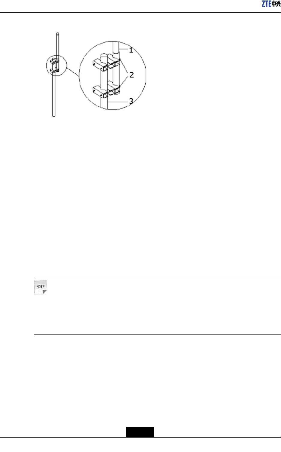
ZXSDRR8860InstallationManual
Figure5-10OmniDirectionalAntennaInstallation
1.Antenna2.Fixingclips3.Antennapole
5.Measuretheverticalityoftheantenna,andensurethatantennaisvertical.
6.Afterensuringtheverticalitytightenthexingclipsrmly.
7.Aftertheantennaisinstalledontothesupport,xtheantennasupportontothetower.
–EndofSteps–
Result
TheOmnidirectionalantennaisinstalled.
5.4.5ConnectingJumperandAntenna
Context
Performthefollowingstepstoconnectjumperwithantenna.
Note:
Theantennajumpercanbeconnectedbeforetheantennamountedontothepole,and
neededtotakethewaterproofmeasurements.Theabovemeasureshighlyreducework
time,providegoodconnection,andimproveswaterpreventionquality.
Steps
1.Connectthejumperconnectortotheantennaport,andtightenitproperly.
2.Sealthejumperconnectorandantennaportforwaterprooftreatment.
a.Wrapthewaterproofadhesivetapeslowersideofconnectors.Keepwrapping
directionsameastheonethatthejumperistightened.
b.Whilewrapping,extendtheadhesivetapestodoubletheirlength.Notethatevery
wrappinglayermustbeoverlappedthepreviouslayerbyhalfthewidthofthetape
5-14
SJ-20100722143906-002|02/20/2011(R1.3)ZTEProprietaryandCondential
Chapter5MainAntennaFeederSystemInstallation
Wrappingmustbeextendedupto50mm(2inches)awayfromjumperconnector
position.
c.Gripthetapewithyourhandstomakethetapetightlyadhered.
d.WrapPVCtapesontopofthewaterproofadhesivetape.Duringtheprocess,
makesuretheupperlayeroverlapsthelowerlayerbyhalfthewidthofthetape.
–EndofSteps–
Result
Thejumperisconnectedwithantenna.
5.5FeederInstallation
5.5.1FeederCuttingPrinciple
Determinelengthofthefeederaccordingtonalfeederroute,andcutthefeeders
accordingtothelengthrequiredofeachfeeder.
Note:
Ifthefeederlengthislessthan10meters,use1/2''feeder;ifthefeederlengthis10~30
meters,use7/8''feederandifthefeederlengthismorethan30meters,use5/4''feeder.
Followingarethetypicalfeedercuttingscenarioobservedon-site:
lIftheantennafeedersystemistobeinstalledonthebuildingroof
1.Measurethelengthofmainfeederforeachsectoraccordingtothenalfeederroute.
2.Addanappropriatemargin(1m(3.3feet)~2m(6.6feet))tothemeasuredlengths
whencuttingthefeeders.
3.Aftercuttingonemainfeeder,attachthetemporarylabelsatbothendsofthefeeder,
suchasANT0andANT2.Attachtheformallabelstothefeederafteritisinstalled.
4.Carrythecutfeederstotheroofofthebuilding,andmakesuretheyarenotsqueezed
ordamagedduringtheprocess.
lIftheantennafeedersystemistobeinstalledonanirontower
1.Hoistoneendofthefeedertothetopofthetowerbyusingapulleyblockandpulling
rope.Beforehoisting,maketheuppermainfeederconnector.
2.Thepersonnelonthetowermustcutthefeederaccordingtothedistancefromthepoint
wherethefeederenterstheroomtothelightningarresterrack,withanappropriate
marginreserved.Makeatemporarylabelforthelowerpart.Attachtheformallabels
tothefeederafteritisinstalled.
5-15
SJ-20100722143906-002|02/20/2011(R1.3)ZTEProprietaryandCondential

ZXSDRR8860InstallationManual
Caution!
Attheendoffeedercuttingprocess,attachlabelatbothends.Temporarylabelscan
alsobeattachedtothemiddleofthefeederduringthefeedercuttingprocess.Makesure
thatalllabelsareconsistentwiththeactualsituation.Otherwise,thefeedermaynotbe
connectedcorrectlyandthesectorsmaynotcorrespondtothefeeder.
5.5.2InstallingFeederonTopofBuilding
Prerequisites
Thesupportingpoleandantennaisinstalled.
Context
Performthefollowingstepstoinstallthemainfeederontopofbuilding:
Steps
1.Firstlydeterminethenalmainfeederroute.
2.Cutthemainfeederaccordingtothedeterminedlengthonthenalroute.
3.Arrangethemainfeederingoodorderwithoutcrossing.
4.Preparetheconnectorsandjumpers.
5.Laythefeedersaccordingtothelayingprinciple.
6.LaythemainfeederalongtothesupportingpoleasshowninFigure5-11.
5-16
SJ-20100722143906-002|02/20/2011(R1.3)ZTEProprietaryandCondential
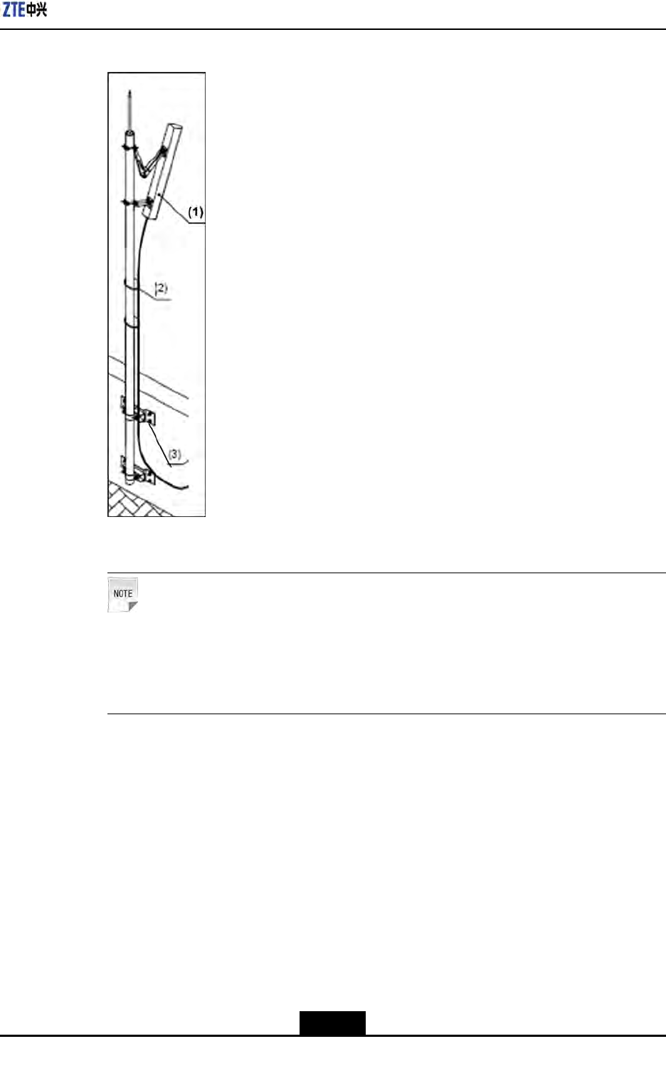
Chapter5MainAntennaFeederSystemInstallation
Figure5-11FeederFixing
1.Antenna2.Feeder3.Supportingclips
Note:
lMakesurethatthefeederlaidistightened.
lThebendingradiusofthefeederisnolessthan20timesofmainfeederradius.
Theradiusofsinglebendisnolessthan90mm(3.54inches),andtherepeated
bendradiusisminimum200mm(7.9inches).
7.Connectfeederwiththeantenna.
–EndofSteps–
Result
Thefeederissuccessfullyinstalledonthetopofbuilding.
5-17
SJ-20100722143906-002|02/20/2011(R1.3)ZTEProprietaryandCondential
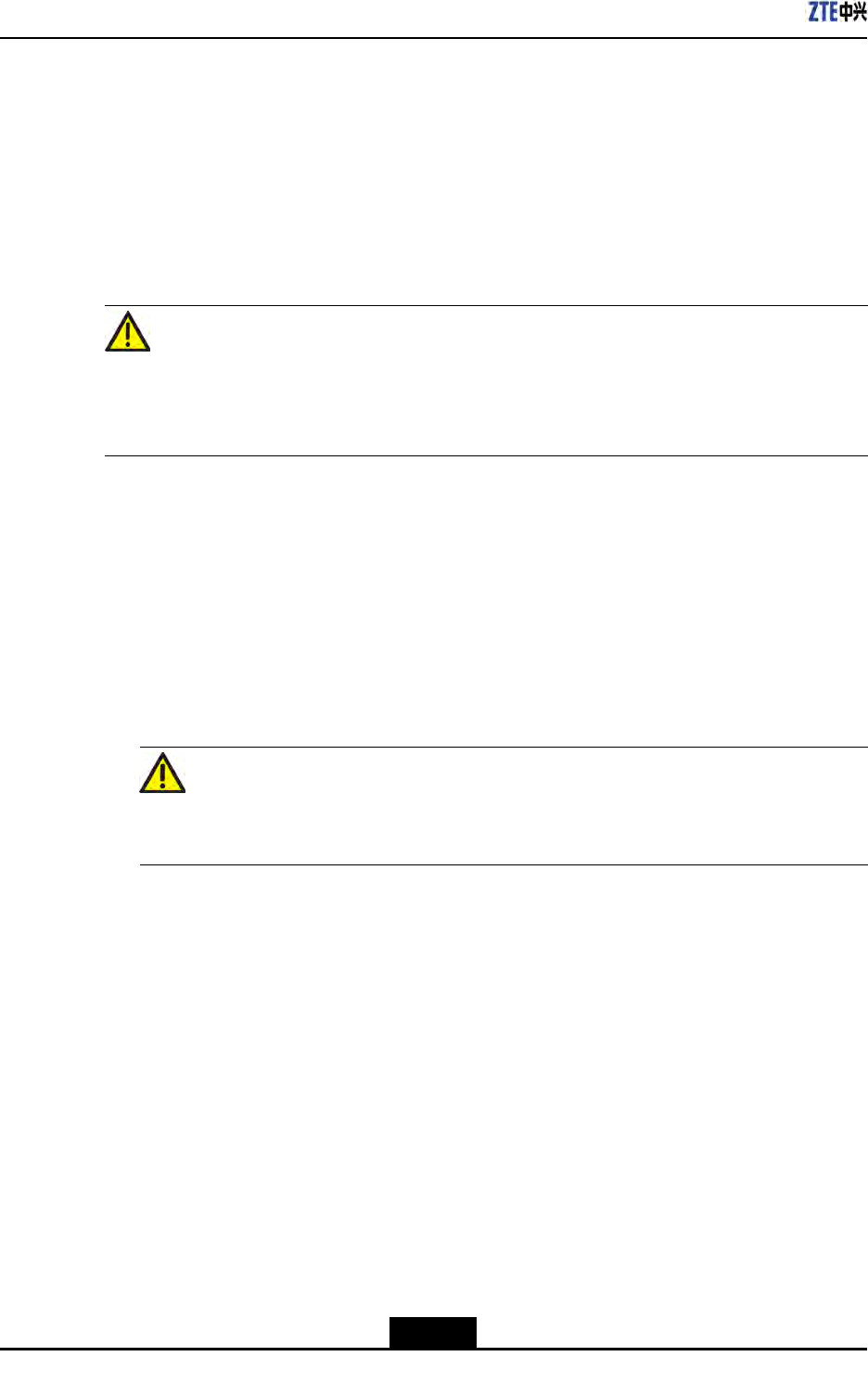
ZXSDRR8860InstallationManual
5.5.3InstallingFeederonTower
Prerequisites
Ensurethatthelabelsareattachedatabout0.3m(1feet)awayfrommainfeederatboth
ends,andarecorrect.
Context
Caution!
lHoistthemainfeederwithcaretoavoiddamagingit'ssheath.Ifanypartofsheathis
damaged,thenitmaycausetheentirefeedertobediscarded.
lTakecareforpersonnelsafetywhenhoistingthefeeders.
Thefeederinstallationinvolvesthefollowingssteps:
Steps
1.Wrapthemainfeederconnectorwithapieceofaxoranantistaticplasticbaglled
withfoam,andthenbindittightlywithcableties.
2.Knotandxthecutfeedercablewithhoistingropeattwopoints.Oneis0.4m(1.5/16
feet)awayfromthefeederconnectorandtheotheroneis3.4m(11.2/16feet)away.
Warning!
Avoidfeederandit'sconnectorfromcollidingwiththeirontower.
3.Afterhoistingmainfeedercablestothetowertop,xupperendofcableatmultiple
pointstopreventitfromslippingdownthetower.
ThefeederhoistingisshowninFigure5-12
5-18
SJ-20100722143906-002|02/20/2011(R1.3)ZTEProprietaryandCondential
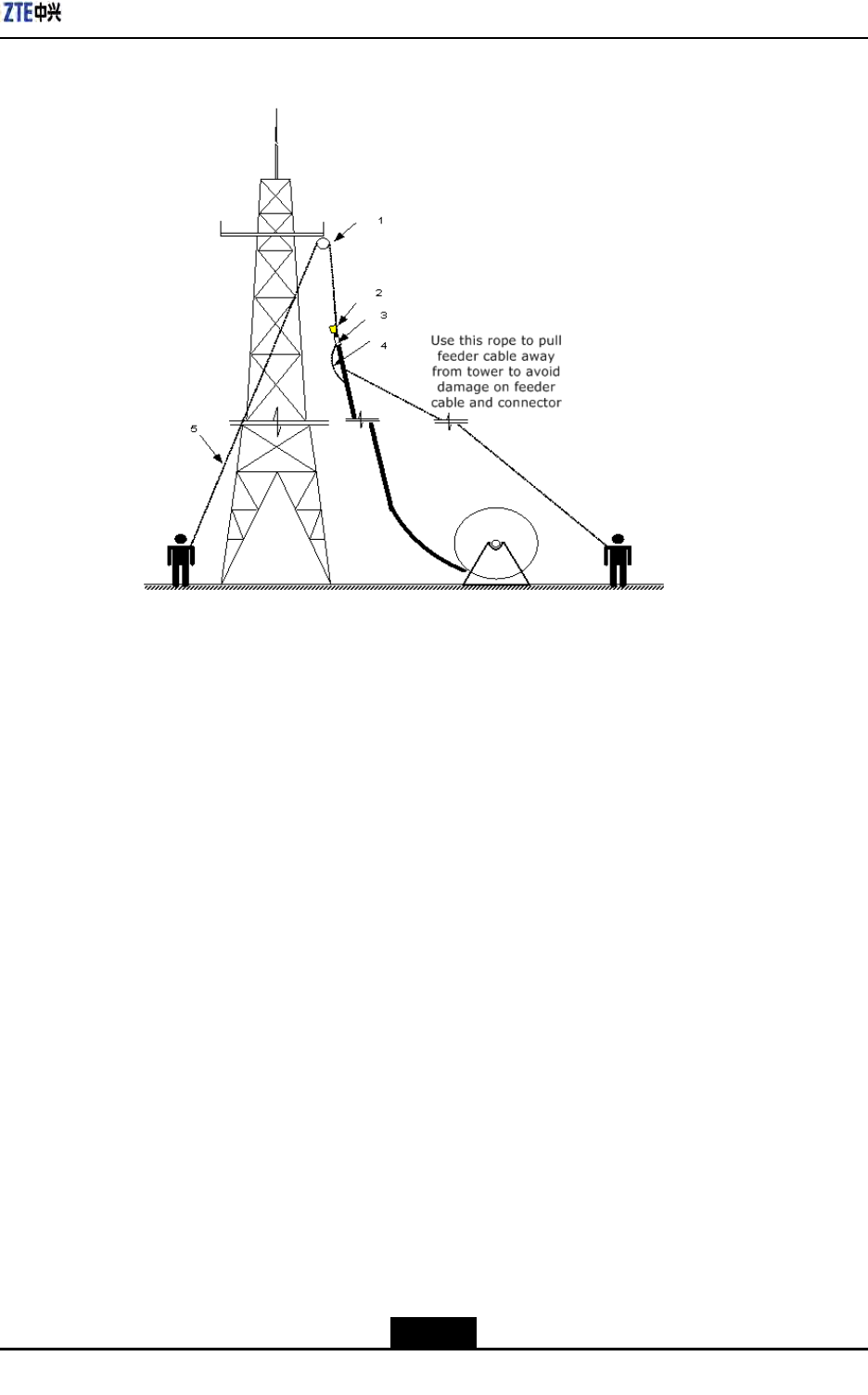
Chapter5MainAntennaFeederSystemInstallation
Figure5-12HoistingFeederToTower
1.Pulleyblock
2.Feederheadwrap
3.Feederlabel
4.Knotpositioninthe
upwardrope
5.Downwardrope
–EndofSteps–
Result
Thefeederishoistedonthetowersuccessfully.
5.5.4FeederLayoutPrinciples
Thefeedershouldbelaidinaccordancewiththefollowingprinciples:
lThemainfeedermustbelaidingoodorderandwithoutcrossings.
lThefeederroutemustbedeterminedbeforeconnectingthemainfeeder.Markthe
actualfeederrouteonadrawingtoavoidreworksduetocrossings.
lTheminimumbendingradiusofthemainfeedershouldbegreaterthan20timesof
themainfeederradius.Thebendingradiusofasinglebendshouldbegreaterthan
90mm(3.54inches).Theminimumbendingradiusofrepeatedbendsis200mm(8
inches).
lIfmorethanonetriplefeederclipsareusedinfeederrouting,thenmaximumdistance
betweentriplefeederclipsshouldbenotmorethan1.65m(5.41feet).
5-19
SJ-20100722143906-002|02/20/2011(R1.3)ZTEProprietaryandCondential
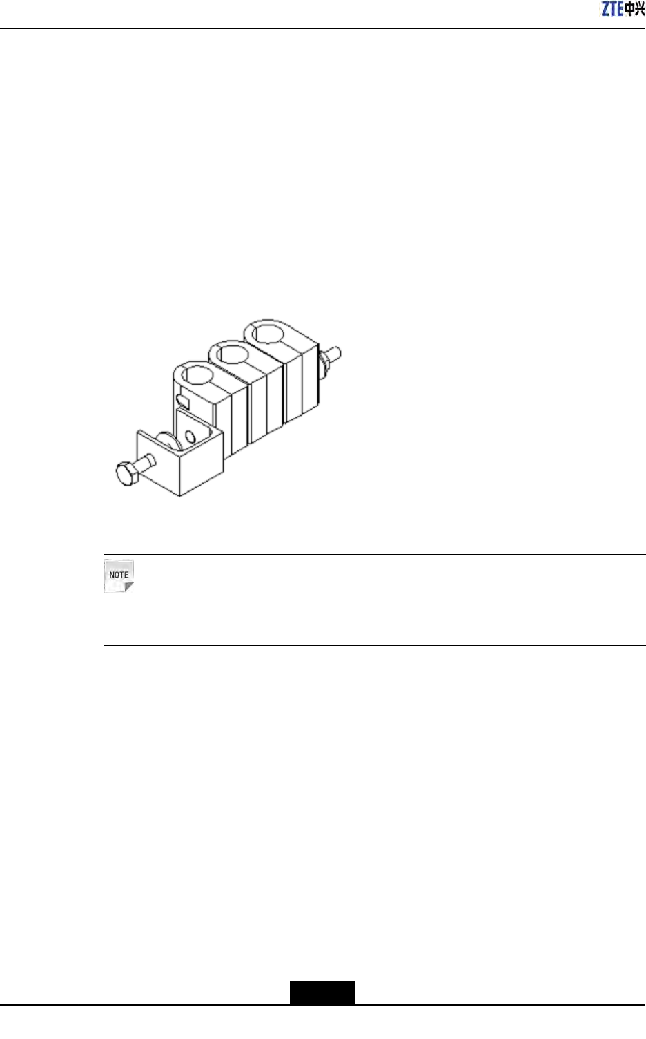
ZXSDRR8860InstallationManual
5.5.5FixingMainFeeder
Context
Performthefollowingstepstoxthemainfeeder:
Steps
1.Firstlyarrangethemainfeederinagoodorder.
2.Fastenmainfeedersfromtopdownwardwiththetriplefeederclipsafterarrangingthe
mainfeeders.Figure5-13showstheappearanceoftriplefeederclip.
Figure5-13TripleFeederClipAppearance
Note:
Donotfastenfeedersatbothendssimultaneously.
3.Keepmainfeedersstraightandinagoodorderwithoutanybulgesbetweenthetriple
feederclips.
4.Tightenthetriplefeederclipsrmly.
–EndofSteps–
Result
Thefeederxingiscompleted.
5.5.6FeederGroundingPrinciple
Thegroundingprinciplesofmainfeederisasfollows:
lToinstallmainantennafeedersystemontower,mainfeedermustbeinstalledwith
feedergroundingclipsatleastinthreeplaces:
5-20
SJ-20100722143906-002|02/20/2011(R1.3)ZTEProprietaryandCondential
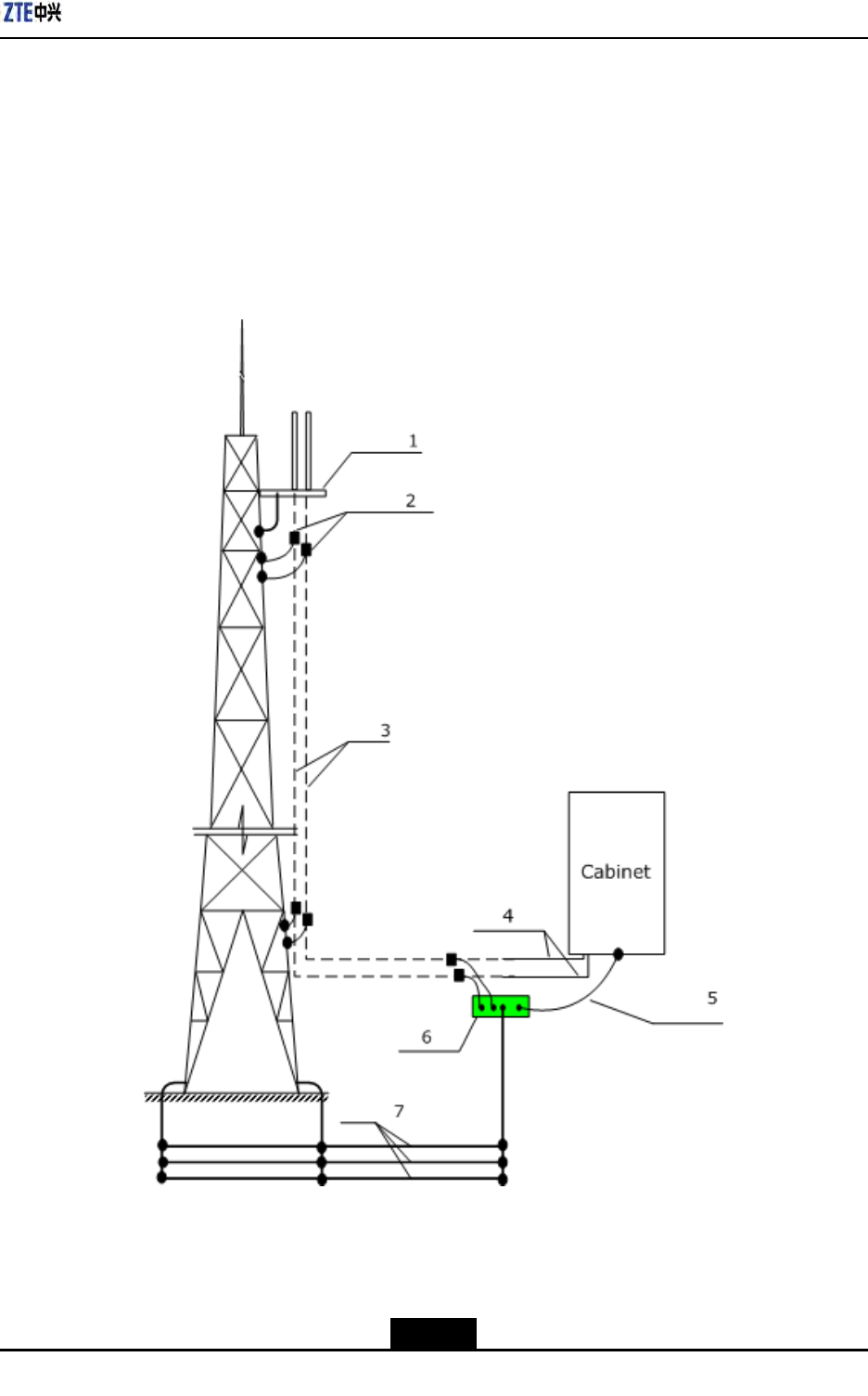
Chapter5MainAntennaFeederSystemInstallation
àTowerplatform
àTheplacewherethemainfeederleavesthetower
àTheplacebeforewherethemainfeederisconnectedtothechassis
Whenthemainfeederisover60m(197feet)inlength,feedergroundingclipsmust
beaddedinthemiddle.Generally,agroundingclipmustbeinstalledonthefeeder
every20m(65.6feet),asshowninFigure5-14.
Figure5-14FeederGroundingSchematicDiagram
1.Towerplatform
2.Feedergroundingclip
3.Feeder
4.Cabinetjumper
5.Groundingcable
6.Groundingbusbar
7.Groundgrid
5-21
SJ-20100722143906-002|02/20/2011(R1.3)ZTEProprietaryandCondential

ZXSDRR8860InstallationManual
lToinstallthemainantennafeedersystemontheroof,itsantennasupportandcable
rackmustbeweldedtothelightningprotectiongridofthebuilding.Themainfeeder
mustbegroundedatthreeplaces:
àTheplacewherefeederleavesthepole
àTheplacewherefeederleavestheroof
àTheplacebeforewherethemainfeederisconnectedtothejumperofthechassis.
lTheoutdoorwiringladderofthemainfeedermustbegrounded.
5.5.7InstallingFeederGroundingClips
ThefeedergroundingclipsinstallationoftheZXSDRR8860isdescribedbelow.
GroundingRequirements
Ensurethefollowinggroundingrequirementswhileinstallingfeedergroundingclips:
lRoofinstallationmode
Inroofinstallation,thefollowingitemsmustbegroundedtobuildgroundingnetwork:
àMainantennasystem
àAntennapole
àOutdoorcablingrackorcablingladder
Groundthemainfeedercableatoneposition,whereitleavesantennapole.Ifthe
feedercableisratherlong,addgroundingpointsaccordingtofeederlength.
lTowerinstallationmode
Usuallyatleasttwofeedergroundingclipsarerequiredtobeinstalledintower
installationmode.Groundthefeedercableatthefollowingpositions:
àWhereitleavesantennainstallationpole
àWhereitleavesirontower
Whenthefeedercableislongerthan60m(197feet),installagroundingcliponthe
feedercableatevery20m(66feet)distance.
Ifoutdoorcablingrackoroutdoorcablingladderisused,grounditreliably.
Antennapolesandirontowerneedtobegroundedreliably.
Figure5-15illustratesgroundingsystemintowerinstallation.
5-22
SJ-20100722143906-002|02/20/2011(R1.3)ZTEProprietaryandCondential
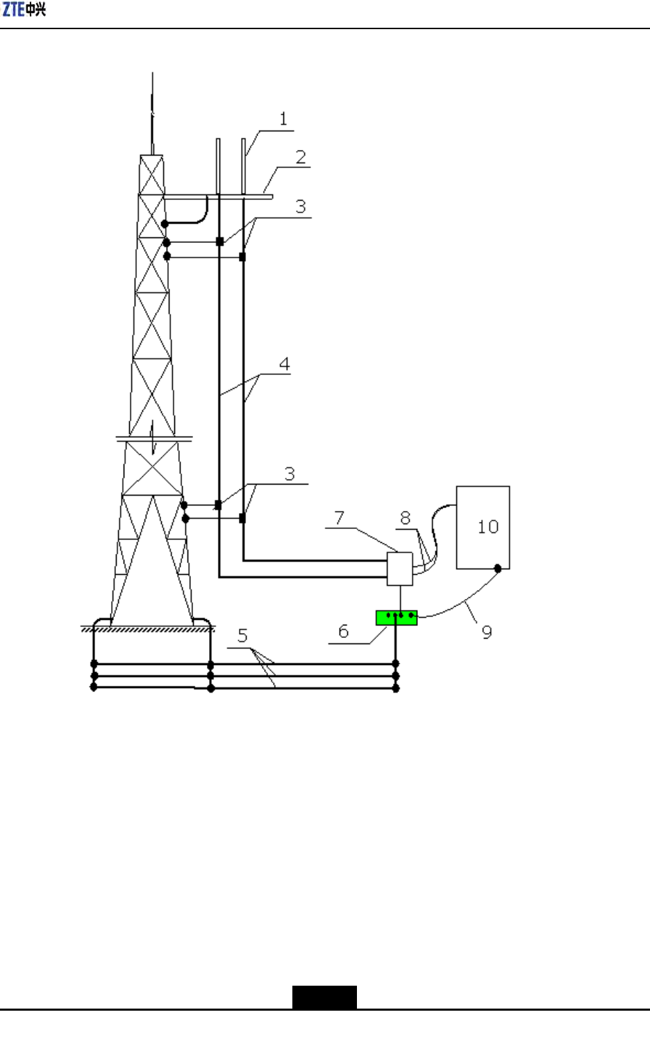
Chapter5MainAntennaFeederSystemInstallation
Figure5-15GroundingSystem
1.Antenna
2.Irontowerplatform
3.Feedergroundingclip
4.Feedercable
5.Groundinggrid
6.Groundingbar
7.Lightningarrester
8.Chassisjumper
9.35mm2(2AWG)grounding
cable
10.ZXSDRR8860chassis
GroundingBarIntroduction
Groundinggridandgroundingbarareusuallyinstalledbytheoperatoremployees.And
thegroundingbarisrequiredtobeinstalledwheretheengineeringdesigndetermineswith
expansionbolts.
Figure5-16illustratesthestructureofthegroundingbar.
5-23
SJ-20100722143906-002|02/20/2011(R1.3)ZTEProprietaryandCondential
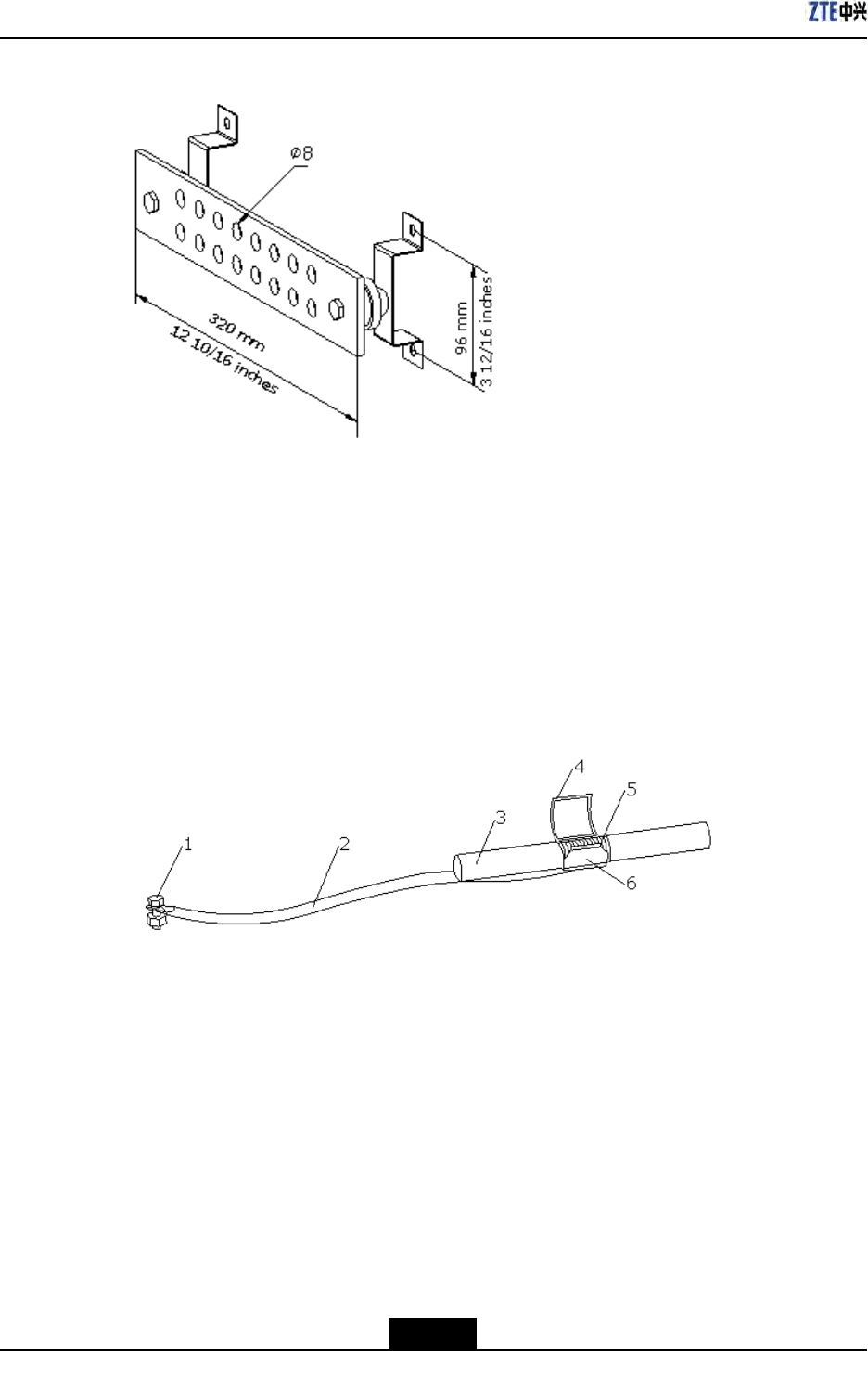
ZXSDRR8860InstallationManual
Figure5-16GroundingBarStructure
InstallationSteps
Performthefollowingstepstoinstallgroundingclip.
1.Preparerequiredtoolsincludingpaperknife,atheadscrewdrivers,andwrenchand
sharp-nosepliers.
2.Peeloff7/8"sheathaccordingtosizeofgroundingclipatthepositions.
Figure5-17illustratesstructureofgroundingclip.
Figure5-17GroundingClip
1.Groundingend
2.Groundingcable
3.Feedercable
4.Groundingspringlock
5.Feederexternal
coppercore
6.Groundingcable
copperpiece
3.Clampthefeederexternalconductorwithgroundingcablecoppersheetandlocking
springplate.
4.Laygroundingcablefacingtothegroundingnetwork.Avoidbendingorfolding.And
keeptheincludedangelbetweengroundingcableandfeedercablelessthan15°.
lIntowerinstallationmode,groundingcableisinstalleddownwardsandnally
connectedtotower
lInroofinstallationmode,groundingcableisinstalledinthesamedirectionwith
feedercables.
5.Makejointofgroundingclipandfeederwaterproofusingwaterproofadhesivetapes,
thenuseinsulationtapestocoverthejoint.
5-24
SJ-20100722143906-002|02/20/2011(R1.3)ZTEProprietaryandCondential

Chapter5MainAntennaFeederSystemInstallation
6.Connectthegroundingendofthegroundingcliptothegroundingnetwork.
lConnectittothemaintowerbodyintowerinstallationmode.
lConnectittothegroundedcablingrackinroofinstallationmode.
Whenconnecting,removethepaintandoxideatconnectionplacewithinaradiusof
13mm(8/16inches)aroundthejoint,anddaubtheplacewithantioxidantcreamto
ensuregoodelectriccontact.Afterconnecting,paintthejointwithanticorrosivepaint.
Note:
Donotinstallgroundingclipincaseofanylightningstrike.
5.5.8ConnectingJumperandFeeder
Prerequisites
Feederconnectorandjumperconnectorisprepared.
Context
Thefollowingproceduresdetailthefeederandjumperconnection.
Steps
1.Fixthe1/2inchjumperconnectorwiththefeederconnector,andscrewthemtightly.
2.SealtheconnectorswithwaterproofadhesivetapesandPVCtapes.
–EndofSteps–
Result
Thejumperisconnectedwiththefeedersuccessfully.
5.6InstallingFeederHermetic-window
Context
Installationrequirementsaredescribedasfollows:
lTheinstallationpositionofhermeticwindowshouldbeclosetoacabletraypossibly.
lThehermeticwindowcanbemountedagainstanindoorwalloroutdoorwallandthe
sideofprotuberantmetalcirclesmustputtowardsoutdoors
lIfthefeederentersintoaroomfromaroof,thehermeticwindowcanbemountedon
theroofandthesideofprotuberantmetalcirclesmustputtowardsoutdoors.
Thefollowdescribesthestepsof12holehermeticwindowinstalledagainstthewall.
5-25
SJ-20100722143906-002|02/20/2011(R1.3)ZTEProprietaryandCondential
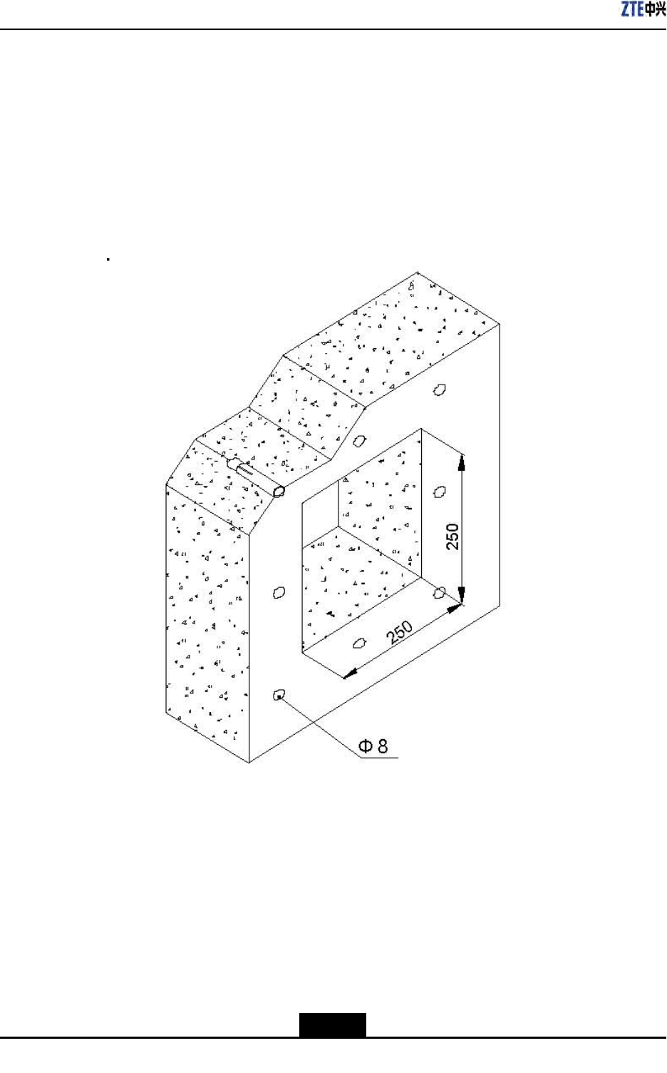
ZXSDRR8860InstallationManual
Steps
1.Accordingtotherequirementsofengineeringdesigndrawingandthedimensionof
hermeticwindow,makesuretheinstallationpositionofhermeticwindowonthewall
andatthesametimemarkholepositionsofexpansionboltsandahollowroomleftfor
thehermeticwindow.
2.Cuta250mm×250mmsquarebigholeandthendrilleightholesofexpansionblots
withapercussivedrill,asshowninFigure5-18.
Figure5-18InstallationHolePositions(Unit:mm)
3.Fixafeederhermetic-windowpanelwithexpansionbolts,asshowninFigure5-19.
Whileinstallingexpansionbolts,rstputaatwasherandthenaspringwasher.
5-26
SJ-20100722143906-002|02/20/2011(R1.3)ZTEProprietaryandCondential

Chapter5MainAntennaFeederSystemInstallation
Figure5-19HermeticWindowInstallation
1.M8×80expansionbolt
2.Feederhermetic-wind
owpanel
–EndofSteps–
5.7FeederIndoorIngoing
5.7.1FeederIndoorArrangementPrinciple
Thearrangementprinciplesoffeederintoaroomcomplywiththefollowing:
lTherearefourbigholesona12–holefeederhermetic-window.Everybigholehas
threesmallholes,everyofwhichafeederpassesthrough.
lAccordingtotheserialNo.ontheengineeringlabelsattachedonthefeeder,layout
thefeederthroughthreesmallholesinthesamebigholeclockwiseoranticlockwise.
lFeederlayoutinthehermeticwindowshouldbeconvenientforcapacityexpansion.
Donotmodifytheinitialfeederlayoutinthehermeticwindowduringcapacity
expansion,andonlyallowaddingfeederormodifyjumperconnectionofcabinet.
lFeederlayoutinthehermeticwindowshouldbeconvenientforlayoutonacabletray
andconnectiontoacabinet.Thefeedershouldbeparallelandnotcrossedduring
routingandconnecting.
5-27
SJ-20100722143906-002|02/20/2011(R1.3)ZTEProprietaryandCondential
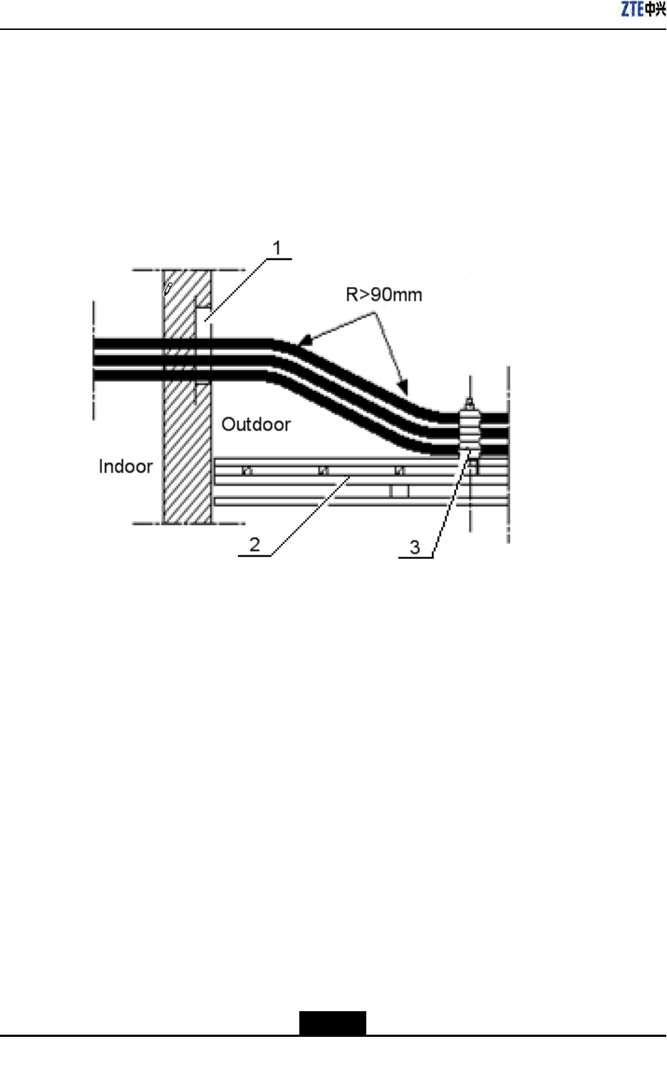
ZXSDRR8860InstallationManual
5.7.2LeadingMainFeederintoRoom
Context
Figure5-20andFigure5-21showtwocommonmodesofmainfeederintoaroom.While
themainfeederisenteringintotheequipmentroom,donotbringwaterintotheequipment
room.
Figure5-20FeederintoRoomMode(1)
1.Feederwindow2.Cabletray3.Feederkit
5-28
SJ-20100722143906-002|02/20/2011(R1.3)ZTEProprietaryandCondential
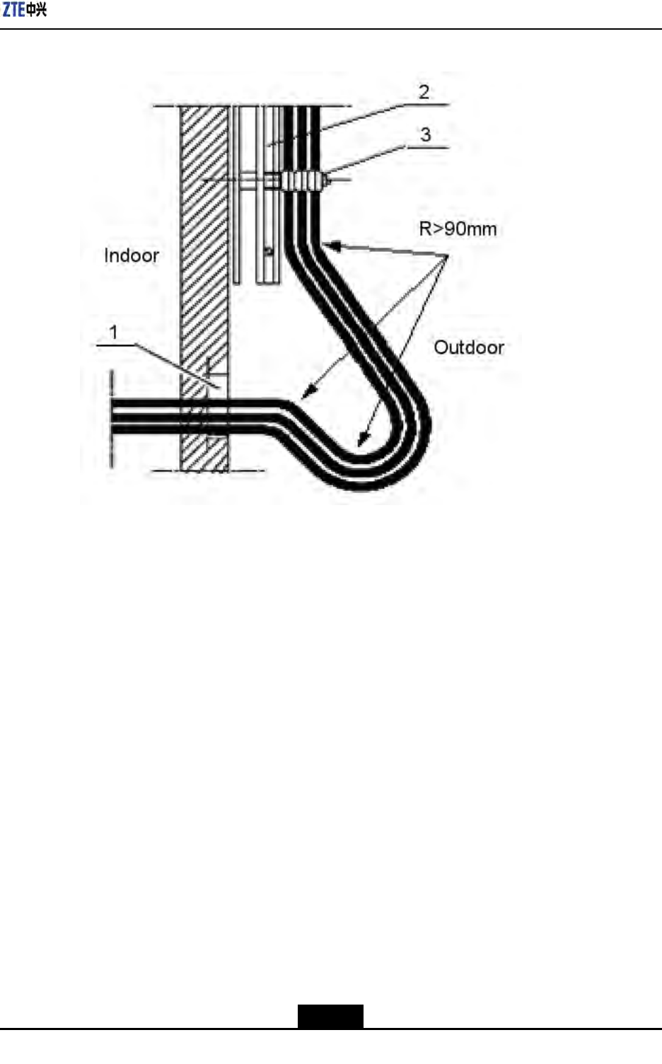
Chapter5MainAntennaFeederSystemInstallation
Figure5-21FeederintoRoomMode(2)
1.Feederwindow2.Cabletray3.Feederkit
Steps
1.Unscrewafastnesshoopoffeederwindowtoproperextent.Pulloutsealingcovers
ofsmallholesthatthefeederpassesthrough.
2.Leadthemainfeederintotheequipmentroom.Whenthemainfeederentersinto
anindoorcabletrayfromanoutdoorcabletray,itisnecessaryfortwoinstallation
personnel'scooperationrespectivelyindoorsandoutdoors.Inthisway,avoid
damagingthemainfeederandotherindoordevicesbyimproperforceduring
installation.Screwdownthefastnesshoopuntilthemainfeederispulltothespecied
position.
3.Cutthemainfeeder.Beforeandaftercutting,makesuretemporarylabelsonthemain
feederintact.
5-29
SJ-20100722143906-002|02/20/2011(R1.3)ZTEProprietaryandCondential

ZXSDRR8860InstallationManual
Note:
Accordingtodetailedequipmentenvironment(forexample,cabinetinstallation
position,jumperlengthonthecabinettop,arrestercongurationorarresterrack
installationposition),thebendingradiusrequirementofmainfeederandthebeautiful
requirementofcablelayoutintheequipmentroom,selectacuttingpositionofmain
feedercable.
4.Makeanindoorconnectorofmainfeeder.
5.Connectthemainfeederwithanarrester.
Note:
lForanarresterwithoutgroundcable,duringinstallation,connectthearresterto
themainfeederdirectly.
lForanarresterwithanarresterrack,duringinstallation,adjusteverymainfeeder
carefully.Makesureascrewfastenerconnectedwellwhichconnectsthemain
feederconnectorwiththearrester.
–EndofSteps–
5.7.3InstallingTop-equipmentJumper
Context
Therequirementsofjumperinstallationareasfollows:
lJumperlayoutfromcabinettoptocabletrayshouldbeparallelandorderly,butnot
crossed.
lDuringrouting,thejumpermustpassthroughthecabletrayinnertoitsupperside.
Prohibitjumpingthecabletrayoutsidesdirectly.
lThebendingofjumperisreasonableandnatural.Suggestthatthebendingradiusof
jumpershouldbetwentytimesmorethanitsdiameter.
lDuringlayoutfromcabinettoptocabletray,thetensilestrengthforthejumpershould
bemoderate.
lThejumpershouldbeboundwitheveryrailofcabletray.Thedirectionsofallwire
fastenerskeepconsistentandafterbinding,thewirefastenersarecutatly.
lLabelsmustbeafxedtoallindoorjumpersata100mmdistancefrombothendsof
jumper.
Steps
1.Thejumperpassesthroughawiringslotonthetopofcabinet.
5-30
SJ-20100722143906-002|02/20/2011(R1.3)ZTEProprietaryandCondential
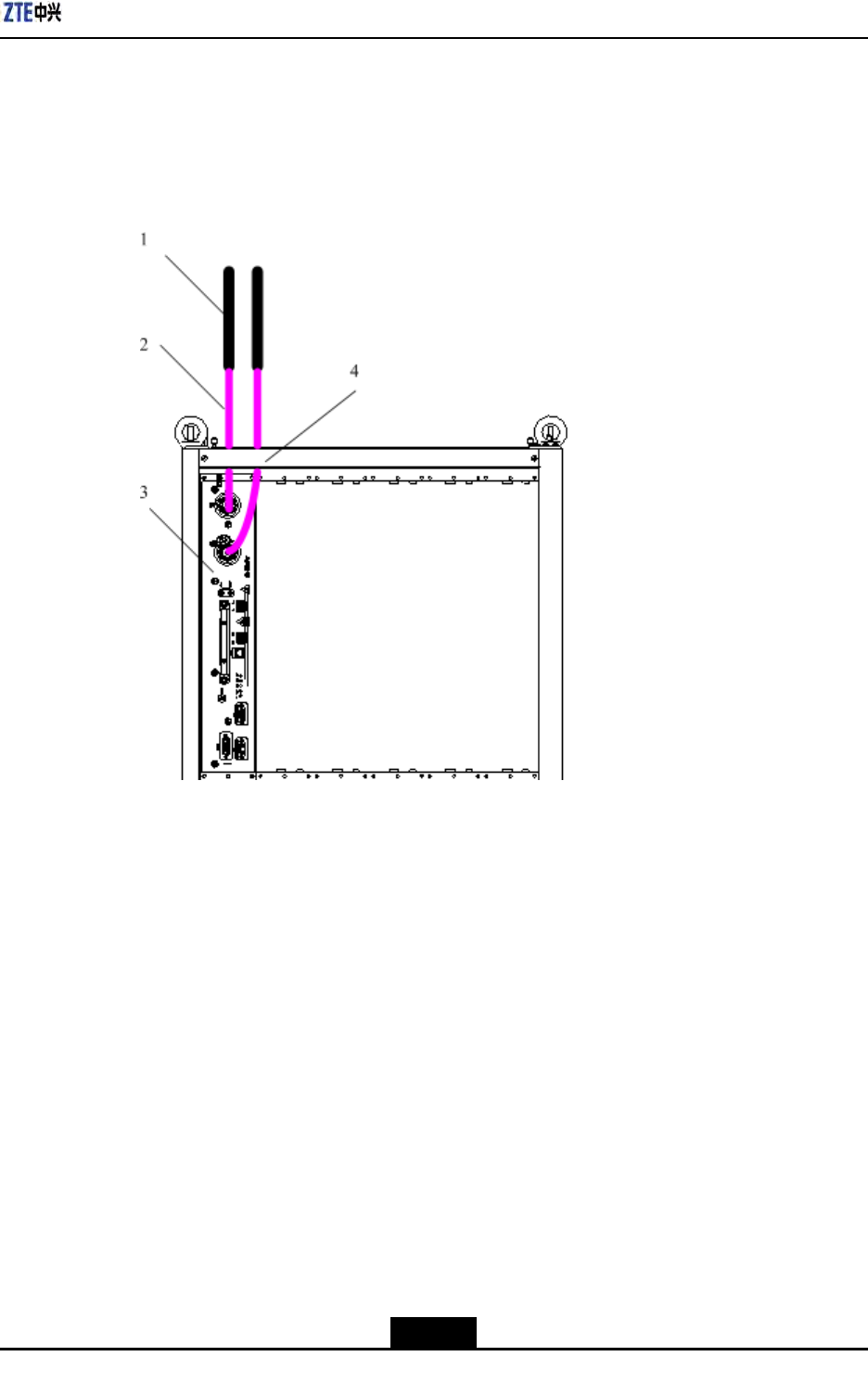
Chapter5MainAntennaFeederSystemInstallation
2.ConnectaDINconnectoroffeedertoanANTinterfaceofRSU.
3.ConnecttheotherDINconnectorofjumpertoaDINconnectoroffeeder.
Figure5-22showstheinstallationprocess.
Figure5-22Antenna,FeederandJumperInstallation
1.Feeder
2.Jumper
3.RSU
4.Wiringslot
4.Afxjumperengineeringlabels.
–EndofSteps–
5.8PerformingAntennaFeederSystemTest
Steps
1.Afterunpacking,checkwhetherasurfaceofantennaandantennaconnectorsare
undamaged.
2.Afterconnectingantennaandjumper,andscrewingdowntheconnector,checkthe
SVWRwithaSVWRtester.
5-31
SJ-20100722143906-002|02/20/2011(R1.3)ZTEProprietaryandCondential

ZXSDRR8860InstallationManual
IfThen
SVWR≥1.5Unqualied
SVWR1.5Qualied
Note:
Duringmeasuring,moveanantennaorchangethepositionofantenna.IftheSVWRs
inalldirectionsareunqualied,itindicatesthattheantennaisfaulty.IftheSVWRs
insomedirectionsareunqualied,checktheantennaafterthewholeantennaand
feedersysteminstalledcompletely.
–EndofSteps–
5.9PerformingOutdoor-ConnectorWaterproof
Processing
Context
Thewaterproofprocessingforoutdoorconnectorsadoptsthe“1+3+3”modetowarp“one
layerPVCinsulatingtape+threelayerwaterproofinsulatingtape+threelayerPVC
insulatingtape”.
ThewaterproofinsulatingtapeisasshowninFigure5-23.
Figure5-23WaterproofInsulatingTape
ThePVCadhesivetapeisasshowninFigure5-24,usedtoprotectconnectorsfrom
damageaswellaswaterprooftapefromaging.
5-32
SJ-20100722143906-002|02/20/2011(R1.3)ZTEProprietaryandCondential
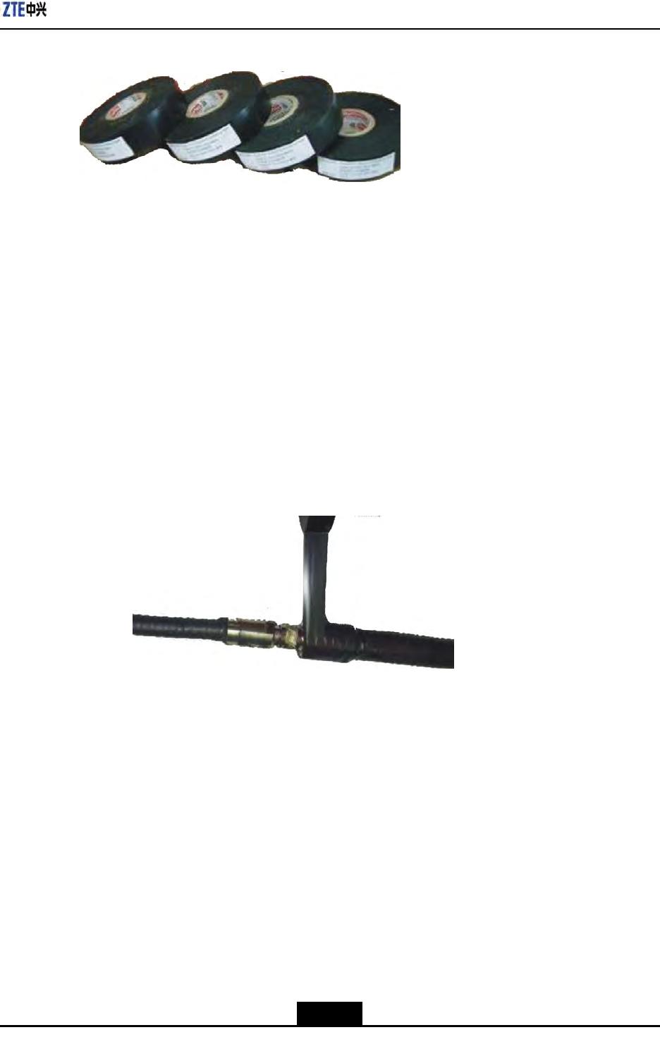
Chapter5MainAntennaFeederSystemInstallation
Figure5-24PVCAdhesiveTape
Steps
1.Cleanthefeederconnectorsandfeedergroundingclips.
2.WrapalayerofPVCinsulatingtape.
a.Cleanoutdustandstainonthefeederconnectororfeedergroundingkit.
b.AsshowninFigure5-25,wrapthefeederwiththePVCinsulatingtapeinan
overlappingwayfromlowertoupper,andtheupperadhesivetapeshouldcover
ahalfoftheloweradhesivetape.Theextendedwidthofadhesivetapeisnot
over1/2longerthantheformerwidth,orelseitdestroysmolecularstructureof
adhesivetapeduetoextensiontoomuch.
Figure5-25WrappingaLayerofPVCInsulatingTape
3.Wrapthreelayersofwaterproofinsulatingtape.
a.Expandthewaterproofinsulatingtapeandstripoffreleasepaper.Theadhesive
tapestickstotheconnectororthefeederwhichis20~50mmawayfromthelower
endofgroundingkit.
b.Extendtheadhesivetapetoupto1/2–3/4oftheformerwidth,inordertokeep
acertainextensionstrength.Bindthefeederinanoverlappingwayfromlower
toupper,andtheupperadhesivetapeshouldcoverahalfoftheloweradhesive
tape,asshowninFigure5-26.
5-33
SJ-20100722143906-002|02/20/2011(R1.3)ZTEProprietaryandCondential
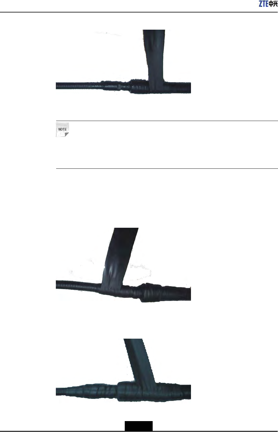
ZXSDRR8860InstallationManual
Figure5-26WrappingThreeLayersofWaterInsulatingTape(theFirstLayer)
Note:
Thewrappingdirectionshouldbetowardsthedirectionofconnectorscrewed
down.Prohibitwrappinginareversedirection.
c.Whilewrappingtothe20~50mmpositionofftheconnector,repeatitfortwice
andthesequencerespectivelyis:fromuppertolowerasshowninFigure5-27
andfromlowertoupperasshowninFigure5-28.
Figure5-27WrappingThreeLayersofWaterInsulatingTape(theSecondLayer)
Figure5-28WrappingThreeLayersofWaterInsulatingTape(theThirdLayer)
5-34
SJ-20100722143906-002|02/20/2011(R1.3)ZTEProprietaryandCondential
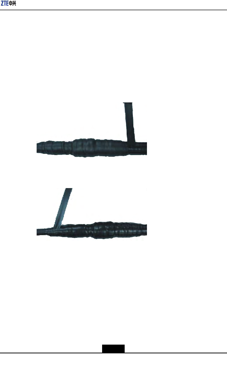
Chapter5MainAntennaFeederSystemInstallation
d.Afterwrappingthewaterproofinsulatingtape,presstheadhesivetapeatthe
bindingwithhandsandmakeitafxedtightly.
4.WrapthreelayerofPVCinsulatingtape.
TwoendsofPVCinsulatingtapemustbe20mmlongerthantheupperlayerof
waterproofinsulatingtape.Bindthefeederinanoverlappingwayfromlowerto
upper,andtheupperadhesivetapeshouldcoverahalfoftheloweradhesivetape,
asshowninFigure5-29.Repeatitfortwiceandthesequencerespectivelyis:from
uppertolowerasshowninFigure5-29andfromlowertoupperasshowninFigure
5-30.Makesureproperstretchstrengthduringwrapping.
Figure5-29WrappingThreeLayersofPVCInsulatingTape(theFirstLayer)
Figure5-30WrappingThreeLayersofPVCInsulatingTape(theSecondLayer)
5.Afternishingwrapping,fastentwowrappedendswithblackfasteners,asshownin
Figure5-31.
5-35
SJ-20100722143906-002|02/20/2011(R1.3)ZTEProprietaryandCondential
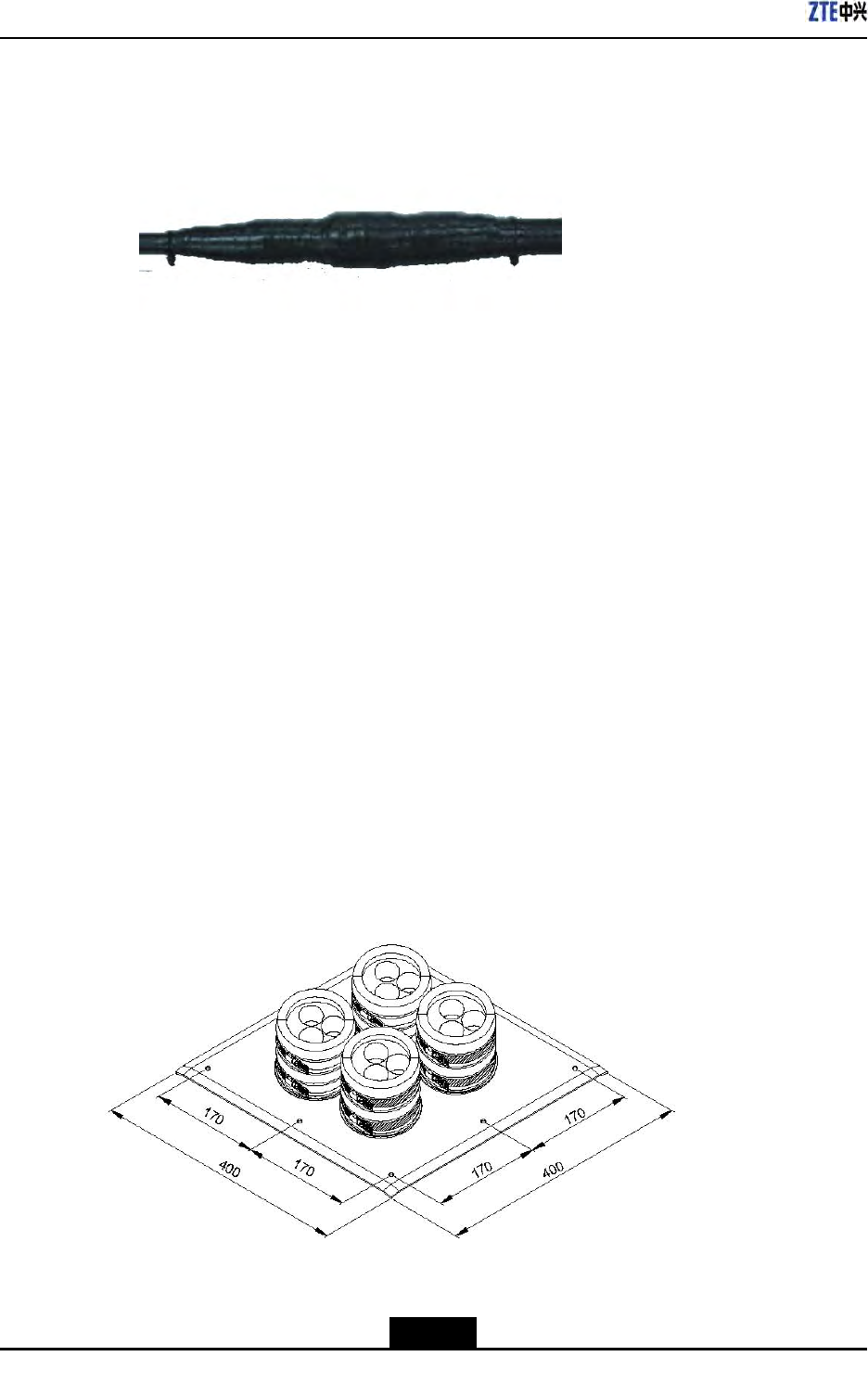
ZXSDRR8860InstallationManual
Figure5-31Fastening
–EndofSteps–
5.10PerformingFeederHermetic-windowWaterproof
Processing
Context
Therearetwotypesoffeederhermetic-window:
l12holefeederhermetic-window
l27holefeederhermetic-window
Normally,adoptthe12holefeederhermetic-window,itsdimensionasshowninFigure
5-32anditsstructureasshowninFigure5-33.
Figure5-32FeederHermetic-windowDimension(Unit:mm)
5-36
SJ-20100722143906-002|02/20/2011(R1.3)ZTEProprietaryandCondential
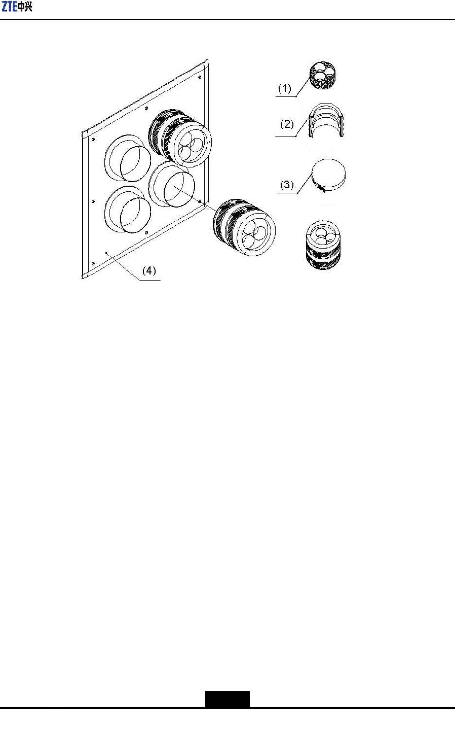
Chapter5MainAntennaFeederSystemInstallation
Figure5-3312FeederHermetic-windowStructure
Installationrequirements:
lTheinstallationpositionofhermeticwindowshouldbeclosetoacabletray.
lThehermeticwindowcanbemountedagainstanindoorwalloroutdoorwallandthe
sideofprotuberantmetalcirclesmustputtowardsoutdoors.
lIfthefeederentersintoaroomfromaroof,thehermeticwindowcanbemounted
againsttheroofandhesideofprotuberantmetalcirclesmustputtowardsoutdoors.
Steps
1.Accordingtotherequirementsofengineeringdesigndrawingandthedimensionof
hermeticwindow,makesuretheinstallationpositionofhermeticwindowonthewall
andatthesametimemarkholepositionsofexpansionboltsandahollowroomleftfor
thehermeticwindow.
2.Cuta250mm×250mmsquarebigholeandthendrilleightholesofexpansionblots
withapercussivedrill,asshowninFigure5-34.
5-37
SJ-20100722143906-002|02/20/2011(R1.3)ZTEProprietaryandCondential
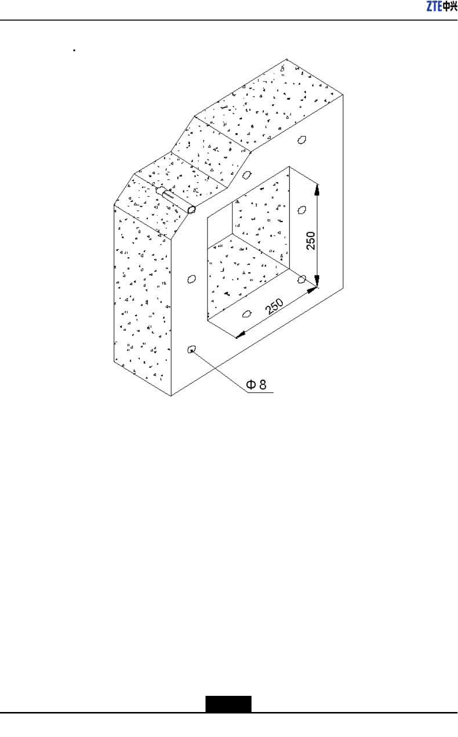
ZXSDRR8860InstallationManual
Figure5-34InstallationHolePositions(Unit:mm)
3.Fixafeederhermetic-windowpanelwithexpansionbolts,asshowninFigure5-35.
Whileinstallingexpansionbolts,aatwasherandaspringwashermustbeinstalled
inturn.
Asealingwasherandasealingcovermaybeinstalledtogetherwithfeederentering
intotheroom.
5-38
SJ-20100722143906-002|02/20/2011(R1.3)ZTEProprietaryandCondential
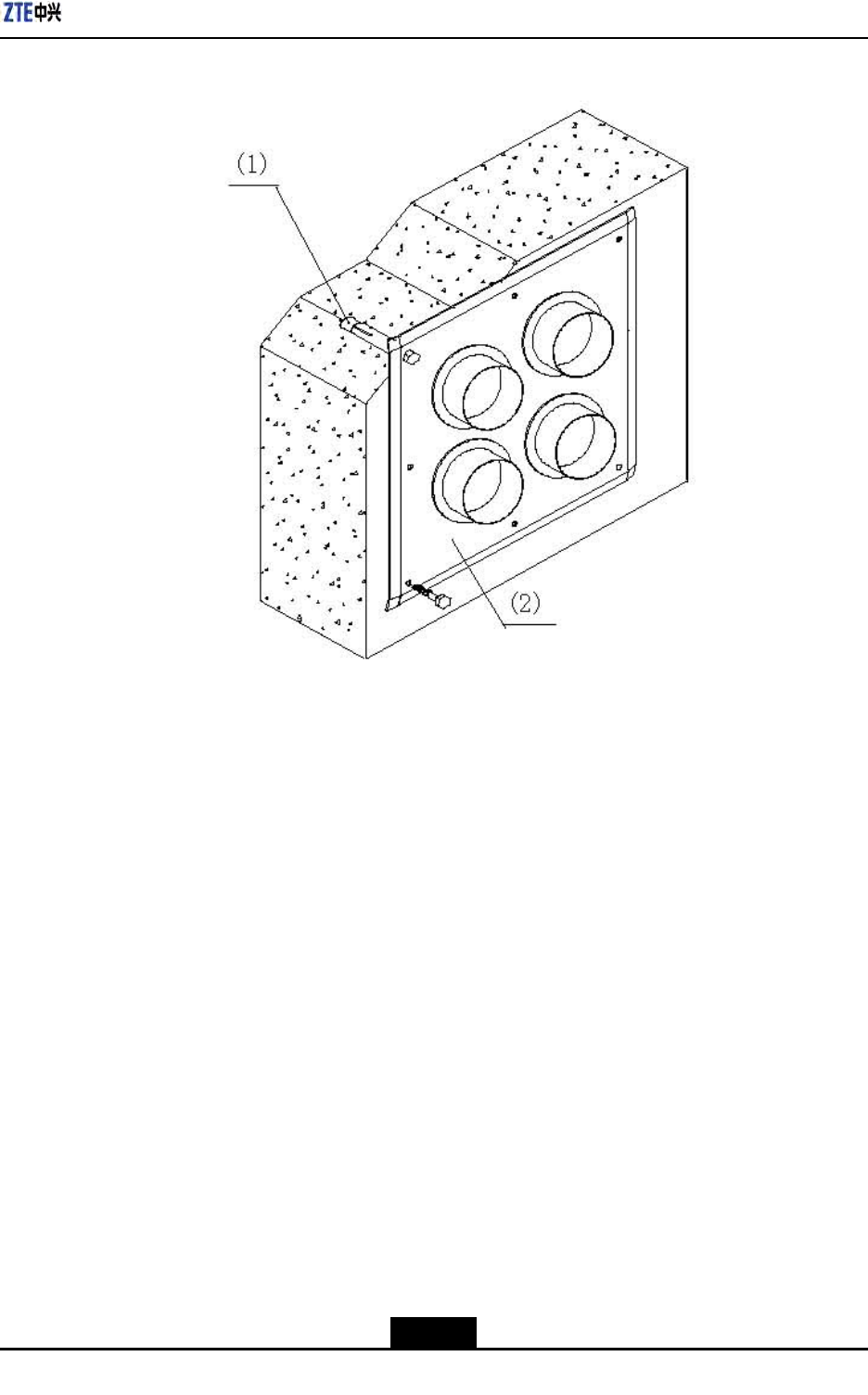
Chapter5MainAntennaFeederSystemInstallation
Figure5-35FeederHermetic-windowInstallation
1.M8×80expansionbolt
2.Feederhermetic-wind
owpanel
–EndofSteps–
5.11ChassisJumperInstallationDescription
TheZXSDRR8860chassisisequippedwithtwoNtypefemaleconnectors.These
connectorsareconnectedtoNtypemaleconnectorsof1/2"jumpers.Thechassisjumper
connectionisasshowninFigure5-36.
5-39
SJ-20100722143906-002|02/20/2011(R1.3)ZTEProprietaryandCondential
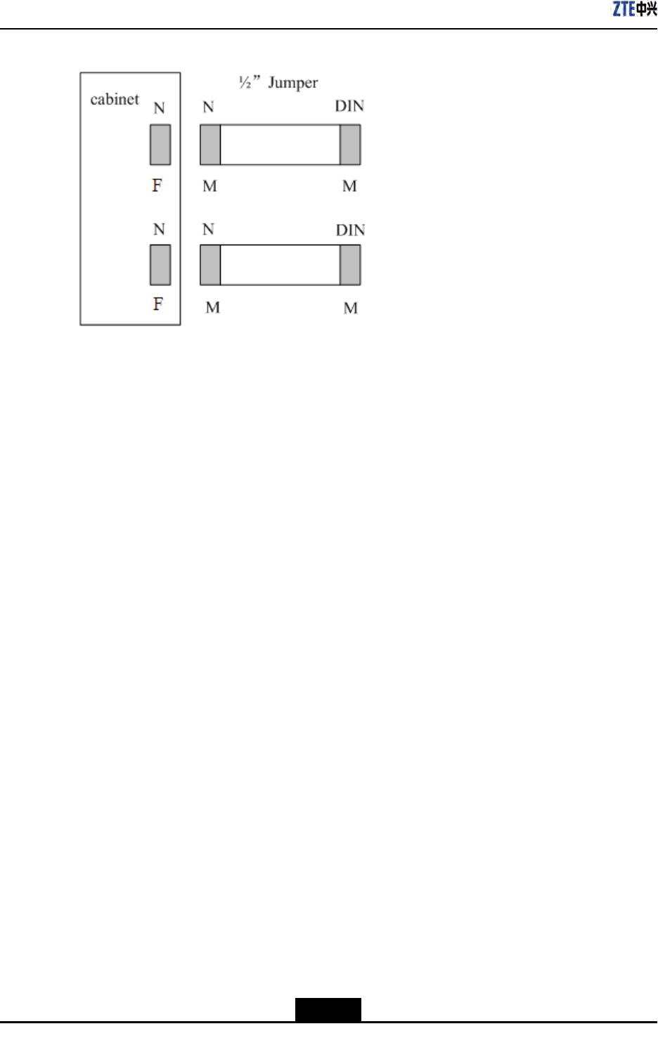
ZXSDRR8860InstallationManual
Figure5-36ChassisJumpers
DINmeansthattheconnectortypeisDIN.
NmeansthattheconnectortypeisN.
"M"indicatesmaleconnectorand"F"indicatesfemaleconnector.
Connectthejumpertothechassis.Makesuretoconnecttherespectiveconnectors
withsimilartypes,suchasNtypeconnectorofjumpershouldbeconnectedwithNtype
interfaceofthechassisandMtypeconnectorofjumpershouldbeconnectedwithMtype
interfaceofthechassis.
5.12VSWRTest
Aftertheinstallationofallantennafeedersandjumpers,conductVSWRtest.TheVSWR
mustbelessthan1.3.Otherwise,checkallmainantennaandfeedersystem,including:
lCheckwhethertheantennafeeders,connectors,andjumpersareintact.
lEnsurethattheconnectionbetweenallpartsareproper.
lCheckwhethertheantennafeederinstallationisperfect.
5-40
SJ-20100722143906-002|02/20/2011(R1.3)ZTEProprietaryandCondential

Chapter6
HardwareInstallation
Inspection
TableofContents
CheckingCabinetInstallation.....................................................................................6-1
CheckingCableInstallation........................................................................................6-1
CheckingMainAntennaSystemInstallation...............................................................6-4
6.1CheckingCabinetInstallation
Steps
1.Ensurethatthecabinetinstallationpositioncomplieswiththeengineeringdesign
drawing.
2.Erectcabinetrmlysoastoresistanearthquakemeasuringupto7.0onRichterscale.
3.Ensurethathorizontalandverticalerrorislessthan3mm.
4.Ensurethatcabinetsurfaceiscleanandtidyandcoveredwellbyoilpaint.Allparts
ofthecabinetarecompleteandallmarkingonthecabinetarecorrect,clearand
complete.
5.Ensureallscrewsarexedtightwithatwashersorspringwashers.
–EndofSteps–
6.2CheckingCableInstallation
6.2.1CablesInstallationGeneralSpecification
OpticalFiber
Note:
Thelengthofopticalberisdecidedbyengineeringsurvey(1Tx,1Rx).
Thetechnicalspecicationsofopticalberareasfollows:
6-1
SJ-20100722143906-002|02/20/2011(R1.3)ZTEProprietaryandCondential
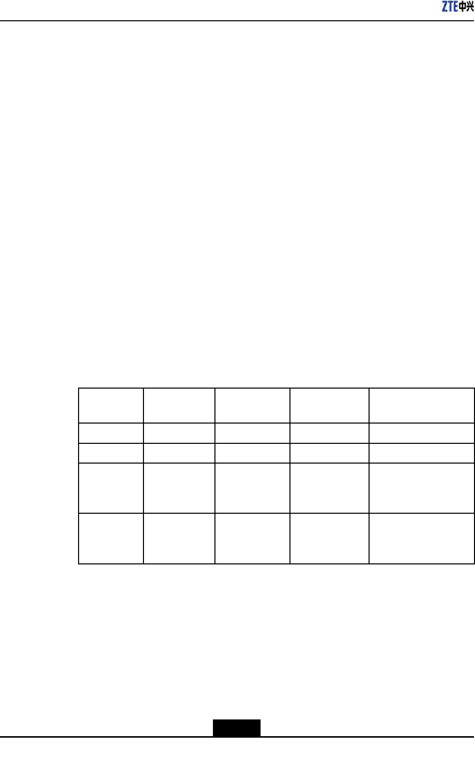
ZXSDRR8860InstallationManual
lTheopticalberisasinglemodewithEndBadoptingtwoDLC/PCconnectors.
lTheinsertionlossislessthat0.3dB.
lThereturnlossislessthan45dB.
lIfopticalberistobeusedoutdoor,then
1.Takewaterproofandanti-ultravioletprotectionmeasures.
2.Makesurethatworkingtemperatureisinbetween-40to80oC.
lThesheathofopticalberisblackincolorwithadiameterof7mm.Underthesheath,
therearetwocoresopticalwires(yellowandbluecolor)withsubstantialamountof
protectionpadding.
lThemaximumdistancebetweencoreopticalwires(includingbothDLC/PC
connectors)andsheathedopticalberis350mm.
lZTEsupplies15m,25m,35m.50m,70m,100m,and130mlongbercables.
lThe20mmlongblackPyrocondensationcannulashouldbeaddedinbetweenoptical
corewiresandsheathedopticalber.
lThelabelattachedatbothendsshouldsatisfytherequirementsofZTECable
DesigningCriteria–LabelDesigningandUsageRequirements.
AISGCable
ThefollowingarethetechnicalspecicationofAISGcable:
lTable6-1illustratestheconnectionrelationshipofbothends.Makesuretoenclose
EndAconnectionbyblackcannulacompletelyafterconnecting.
Table6-1ConnectionRelationship
Serial
Number
Signal
Denition
EndAPin
Number
EndBPin
Number
ConnectedCable
1485+Pin3Pin1-
2485-Pin5Pin2-
328VPin6Pin3,4TwocablesfromPin6
ofAendareweldedto
Pin3and4ofBend.
428VGNDPin7Pin5,6TwocablesfromPin7
ofAendareweldedto
Pin5and6ofBend.
lThePin6andPin7(SeeTable6-1)areneededtobeweldedwithtwocables.
lTheEndAconnectorshouldbeequippedwithmetaldust-proofcover
lThelabelsprintingandpastingshouldsatisfytherequirementsofQ/ZX04.113.4Cable
DesigningCriteria–LabelDesigningandUsageRequirements.
MonitoringCable
Thefollowingarethetechnicalspecicationofmonitoringcable:
lTheEndAisa37-pinfemaleconnector.
6-2
SJ-20100722143906-002|02/20/2011(R1.3)ZTEProprietaryandCondential
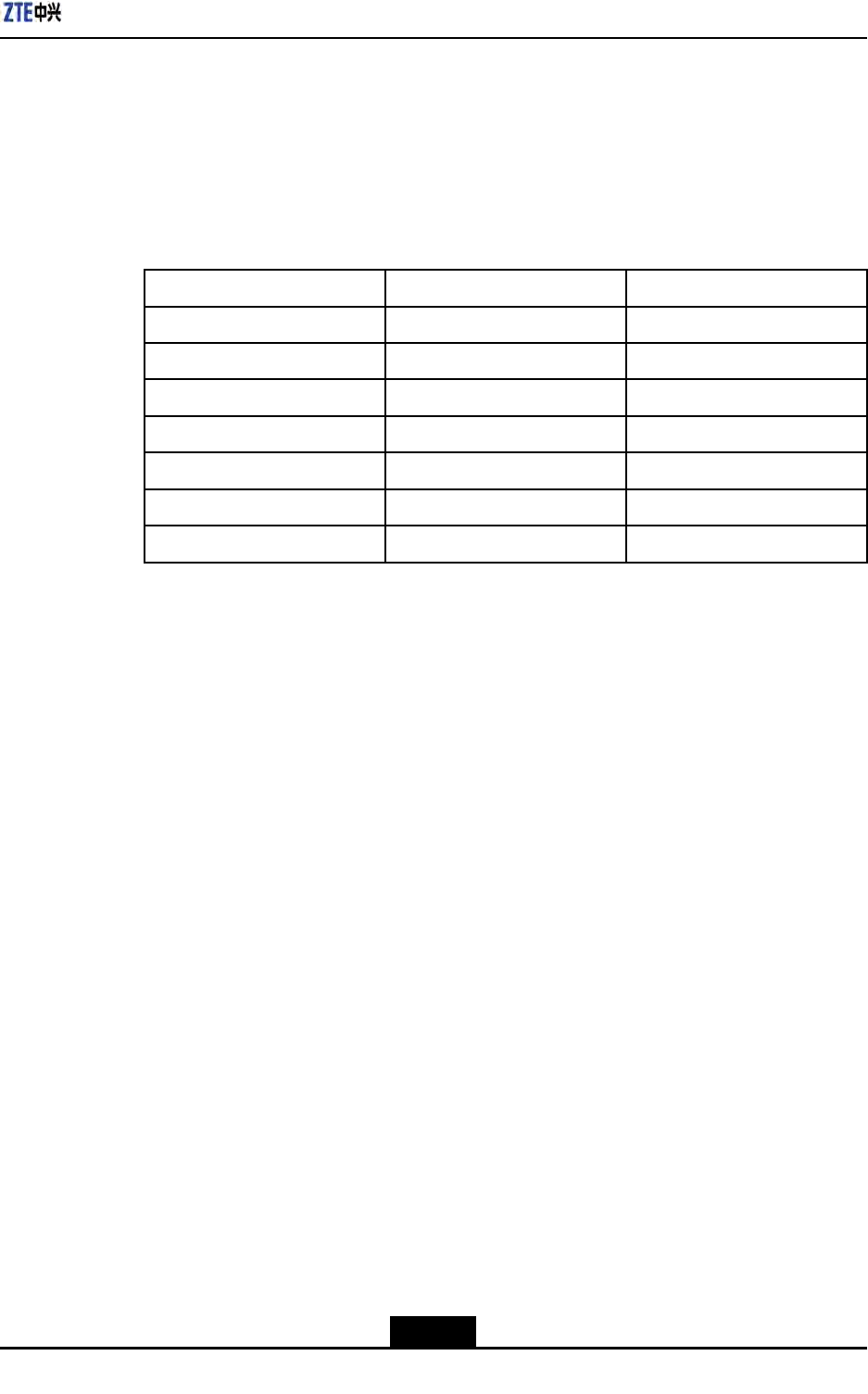
Chapter6HardwareInstallationInspection
lEndBisanopenendwithoutanyconnector.TheconnectorattheEndBshouldbe
preparedon-siteaccordingtotheon-siterequirements.
lMakesurethatconnectorattheEndAisproperlywelded.
lThelabelattachedatbothendsshouldsatisfytherequirementsofZTECable
DesigningCriteria–LabelDesigningandUsageRequirements.
lTable6-2showstheconnectionrelationshipofEndA.
Table6-2ConnectionRelationship
EndA(Pins)ColorSignalDenition
15/16White/blueDrycontact4-/+
17/18White/orangeDrycontact3-/+
19/20White/greenDrycontact2-/+
21/22White/brownDrycontact1-/+
23/24Red/blue485Rx-/+
25/26Red/orange485Tx-/+
OtherPinsarefreeOthercorewiresarefree
6.2.2PowerandGroundingCablesInstallationCheck
Context
Ensurethepowerandgroundingcablesinstallationisdoneinaccordancewiththe
followingchecks:
Steps
1.Thepowerandgroundingcablesarelaidseparatelyfromothercables.Ifthepower
andgroundingcablesaretobelaidparallelwithothercables,thenatleastadistance
of20cmismaintainedbetweenthem.
2.Thecablelabelsareintactonbothsidesofpowerandgroundingcables.Thelabels
areattachedatalmost2cmfromcablecopperlug.
3.Entirepowerandgroundingcablesaremadefromonematerialwithnoconnections
inbetween.
4.Asinglegroundingpointonthegroundingbusbarjustconnectstoapieceof
equipment.
5.Copperlugsonbothendsofpowerandgroundingcablesaresolderedorpressed
rmly.
6.Theshortestroutebetweenthegroundingcablesandgroundingbusbarisadopted.
7.Powerandgroundingcablesatconnectingterminalsandlughandlesareproperly
insulatedusingeitherinsulatedtapesorheatshrinktubes.
6-3
SJ-20100722143906-002|02/20/2011(R1.3)ZTEProprietaryandCondential

ZXSDRR8860InstallationManual
8.Theredundantlengthofpowerandgroundingcablesiscuttoavoidwrappingeach
other.
–EndofSteps–
6.2.3OpticalFiberInstallationCheck
Context
Thebercableinstallationshouldmeetthefollowingspecications:
Steps
1.Donotfoldopticalberat90o.Foropticalberthatistobelaidoutdoors,minimal
twistradiusshouldbeatleastgreaterthan90mm.Whereasforopticalberthatisto
belaidindoors,minimaltwistradiusshouldbeatleastgreaterthan30mm.
2.Afterinstallation,anysurplusopticalbershouldbeputbackinthebercardfor
convenience.
3.Duringinstallation,minimizeopticalbertwistandturn,asmuchaspossible.
4.Thebindingforceshouldbepropertoensurethatbindinggapsareless0.5m.
5.Makesurethatlabelsatbothendsofopticalberareintactandclear.
–EndofSteps–
6.3CheckingMainAntennaSystemInstallation
Steps
1.Ensuretheheightofantennaisconsistentwiththenetworkplanning,andthe
installationpositionisconsistentwiththeengineeringdesigndrawing.
2.Ensuretheazimuthanddown-tiltoftheantennaisconsistentwiththeengineering
designdrawing.
3.Ensuretheantennaiswithintheprotectionareaoflightningrod.
4.EnsuretheVSWRnotmorethan1.5
5.Ensureproperconnectionbetweenantennaandjumperaswellasbetweenjumper
andmainfeedercorrect.
6.Makesurethatthejumperandantennaatthejunctionkeepstraightwithin30cmat
least.
–EndofSteps–
6-4
SJ-20100722143906-002|02/20/2011(R1.3)ZTEProprietaryandCondential

Chapter7
Poweronandoff
TableofContents
PoweronPreparation.................................................................................................7-1
PowerON..................................................................................................................7-1
PowerOFF.................................................................................................................7-2
7.1PoweronPreparation
Context
Makesurethatfollowingconditionsarefullledbeforepowering-onZXSDRR8860:
Steps
1.Makesurethatinputpowersupplyiswithintheacceptablerange.
2.MakesurethatpowercableconnectedtoZXSDRR8860cabinetisproperlygrounded.
–EndofSteps–
Result
Thepreparationtopoweronthecabinetissuccessfullycompleted.
7.2PowerON
Context
Performthefollowingstepstopower-ontheZXSDRR8860.
Steps
1.ThereisnopowerswitchONtheZXSDRR8860cabinet.Closetheexternalpower
switchtopoweronZXSDRR8860.
2.DuringpowerON,ifsomeabnormalphenomenaoccurs,disconnecttheexternal
powerswitchortheplugimmediately,andcheckthereason.
–EndofSteps–
7-1
SJ-20100722143906-002|02/20/2011(R1.3)ZTEProprietaryandCondential

ZXSDRR8860InstallationManual
7.3PowerOFF
Context
PerformthefollowingstepstopowerOFFtheZXSDRR8860.
Steps
1.ThereisnopowerswitchontheZXSDRR8860cabinet.Disconnecttheexternalpower
switchtopoweroffZXSDRR8860.
–EndofSteps–
7-2
SJ-20100722143906-002|02/20/2011(R1.3)ZTEProprietaryandCondential
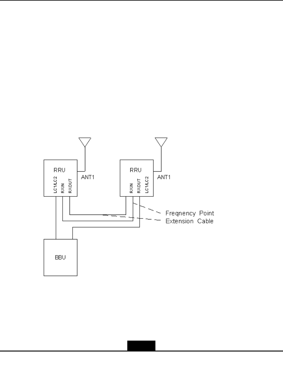
AppendixA
Cabinet-combined
Installation
TableofContents
ŸComponentsUsedinCabinet-combiningInstallation..............................................A-1
ŸPerformingCabinet-combination.............................................................................A-2
A.1ComponentsUsedinCabinet-combining
Installation
Bycombiningcabinets,theZXSDRR8860cansupport8carriersectors.FigureA-1shows
theconnectionforcombiningtwoZXSDRR8860cabinets.
FigureA-1ZXSDRR8860Cabinet-combinedInstallationConnection
1.FrequencyPointExtension
Cable
A-1
SJ-20100722143906-002|02/20/2011(R1.3)ZTEProprietaryandCondential

ZXSDRR8860InstallationManual
Note:
TheRRUinFigureA-1meanstheZXSDRR8860.
Thedescriptionofcabinet-combinedconnectionareasfollows:
1.TwoZXSDRR8860cabinetsareconnectedbytwofrequencypointextensioncables.
2.TwoZXSDRR8860cabinetsprovidesmutualreceivingdiversityforeachother.Each
ZXSDRR8860isequippedwithofapairofantennatotransmitandreceivesignals.
Thecomponentsusedinthecabinet-combinedinstallationaredescribedasfollows:
1.Whileselectingthepole-mountinstallation,refertoComponentsUsedin
Pole-mountInstallation);whileselectingthewall-mountinstallation,referto
ComponentsUsedinWall-mountInstallation;whileselectingthegantry-mount
installation,refertoComponentsUsedinGantry-mountInstallation.
2.Twofrequencypointextensioncablesareprepared.
A.2PerformingCabinet-combination
Steps
1.Selectaproperinstallationmode(pole-mountinstallation,wall-mountinstallationand
gantry-mount)accordingtotheactualconditionstoinstalltwoZXSDRR8860.
2.Connectthetwofrequencypointextensioncablesasdescribedbelow:
a.ConnectEndAofafrequencypointextensioncabletotheRXininterfaceofa
ZXSDRR8860andEndBtotheRXoutoftheotherZXSDRR8860.
b.ConnectEndAoftheotherfrequencypointextensioncabletotheRXoutofthe
ZXSDRR8860andEndBtotheRXinoftheotherZXSDRR8860.
–EndofSteps–
A-2
SJ-20100722143906-002|02/20/2011(R1.3)ZTEProprietaryandCondential
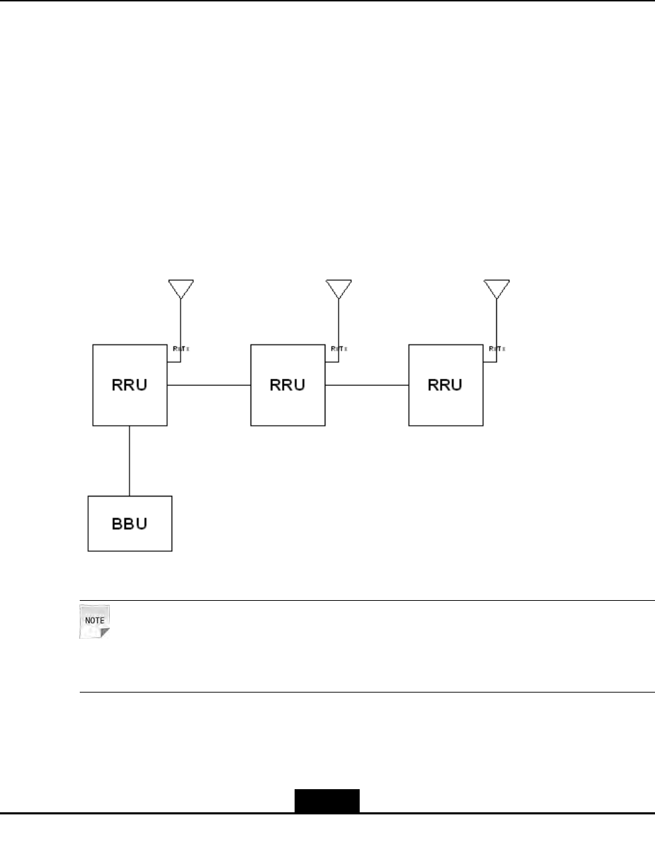
AppendixB
CascadingCabinet
Installation
TableofContents
ŸComponentsUsedinCascadingInstallation...........................................................B-1
ŸPerformingCabinetCascading...............................................................................B-2
B.1ComponentsUsedinCascadingInstallation
MultipleZXSDRR8860cabinetscanbeconnectedinseriesbyusingopticalbers,forming
achainnetwork.FigureB-1showsthecascadedcabinets.
FigureB-1CascadedCabinetConnection
Note:
TheRRUinFigureB-1meansZXSDRR8860.
1.OneZXSDRR8860isconnectedtoanotherZXSDRR8860ortoBBUbyopticalbers.
EachZXSDRR8860providestwoopticalportsthatareidentiedbyLC1andLC2
respectively.
B-1
SJ-20100722143906-002|02/20/2011(R1.3)ZTEProprietaryandCondential
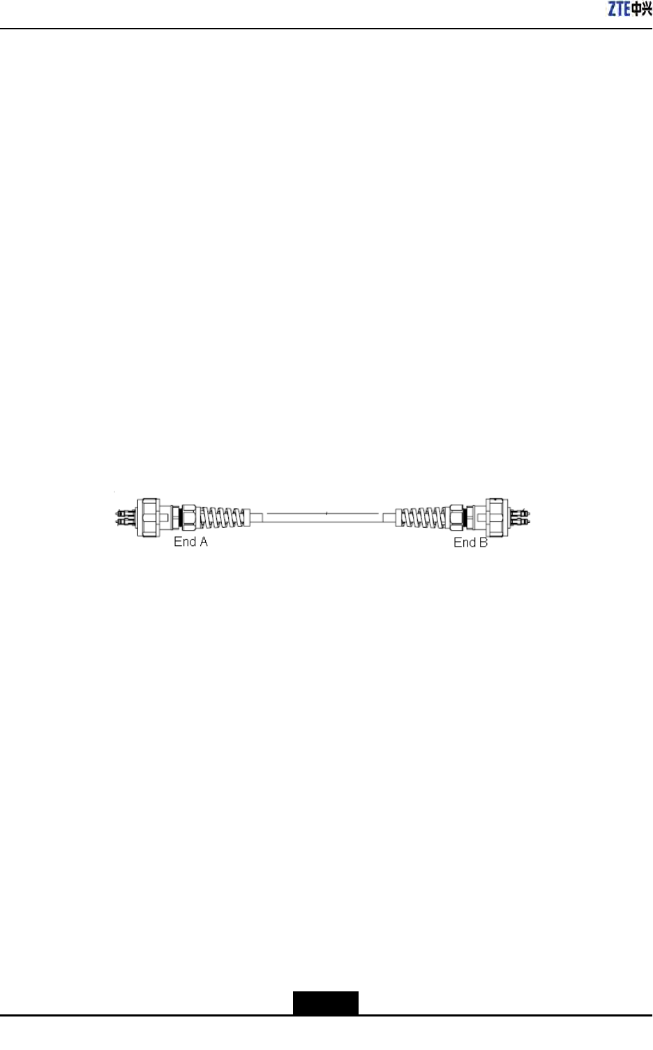
ZXSDRR8860InstallationManual
2.Generally,theLC1servetoconnecttheBBUortheupperlevelZXSDRR8860while
theLC2toconnectthelowerlevelZXSDRR8860.
Thecomponentsusedinthecascadinginstallationaredescribedasfollows:
1.Whileselectingthepole-mountedinstallation,refertoComponentsUsedin
Pole-mountInstallation);whileselectingthewall-mountedinstallation,referto
ComponentsUsedinWall-mountInstallation;whileselectingthegantry-mount
installation,refertoComponentsUsedinGantry-mountInstallation.
2.Connecttheopticalber.
B.2PerformingCabinetCascading
Steps
1.Selectaproperinstallationmode(pole-mountorwall-mount)toinstalltheZXSDR
R8860cabinet.
2.Useopticalberstoconnectcabinetsincascade.
FigureB-2showstheopticalbertoconnectcabinetincascade.
FigureB-2ZXSDRR8860OpticalFiberforCascadedCabinet
Followingistheconnectionscheme.
a.ConnectEndAofopticalbertotheLC1/LC2interfaceofoneZXSDRR8860.
b.ConnectEndBofopticalbertotheLC1/LC2interfaceoftheotherZXSDRR8860.
–EndofSteps–
Result
Thecascadedcabinetsareinstalledsuccessfully.
B-2
SJ-20100722143906-002|02/20/2011(R1.3)ZTEProprietaryandCondential
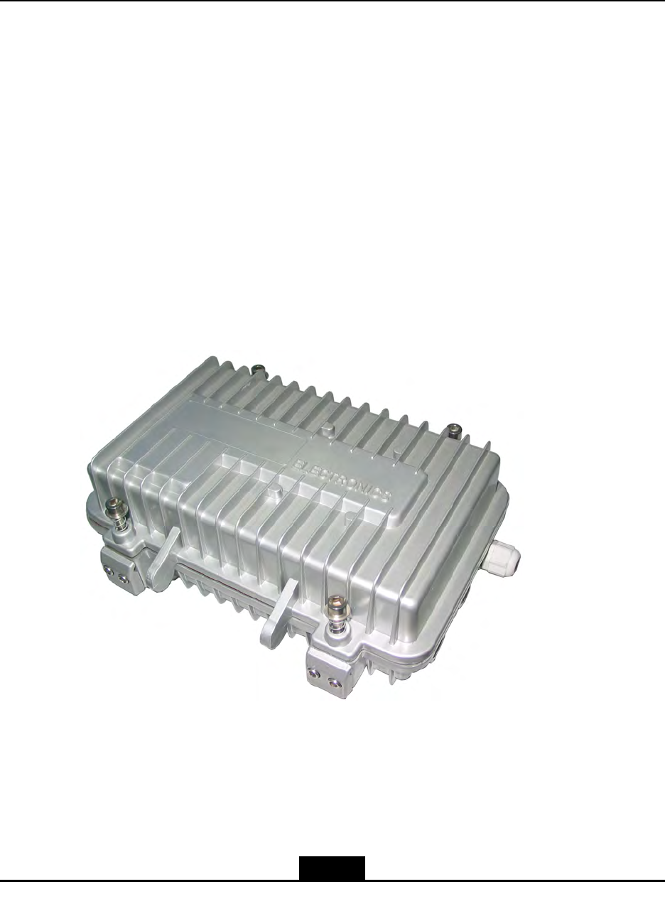
AppendixC
OAU
TableofContents
ŸOAUAppearanceandInterface..............................................................................C-1
ŸInstallingOAUinPole-mountMode........................................................................C-2
ŸInstallationOAUinWall-mountMode......................................................................C-9
ŸInstallingOAUCable............................................................................................C-12
C.1OAUAppearanceandInterface
Appearance
TheappearanceofOAUisasshowninFigureC-1.
FigureC-1OAUAppearance
Interface
TheinterfacesofOAUisasshowninFigureC-2.
C-1
SJ-20100722143906-002|02/20/2011(R1.3)ZTEProprietaryandCondential
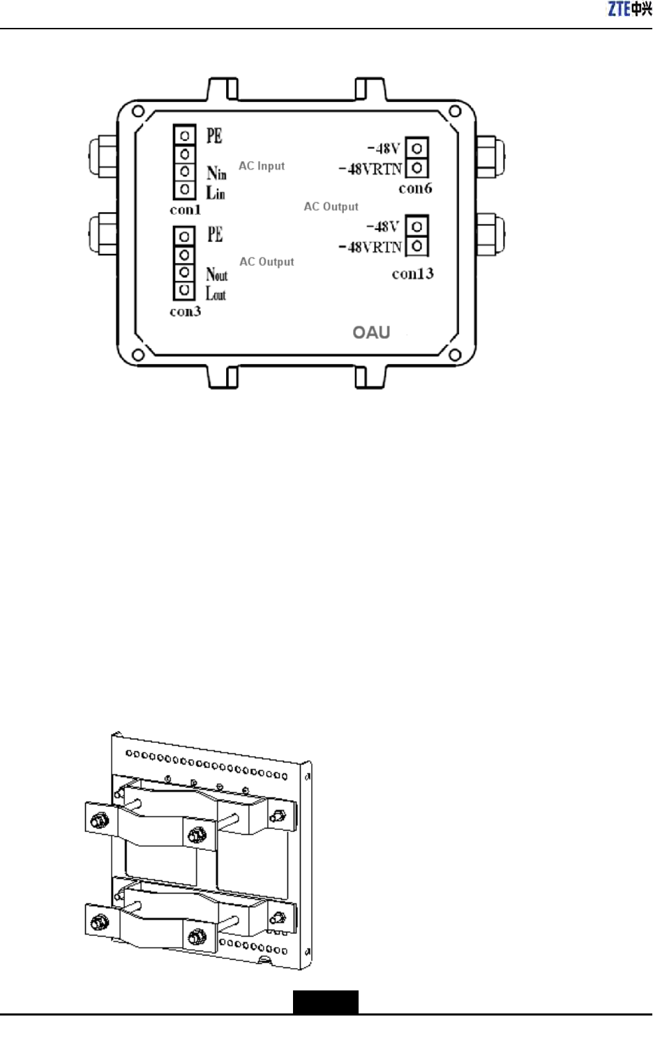
ZXSDRR8860InstallationManual
FigureC-2OAUInterfaces
C.2InstallingOAUinPole-mountMode
Prerequisites
UnpackingandacceptanceforoutdoorACunit(OAU)iseligible.
Context
TheOAUpole-mountmodecanadoptanchorclampassembliesorxingbracket
assemblies.TheanchorclampassembliesareasshowninFigureC-3andthexing
bracketassembliesareasshowninFigureC-4.
FigureC-3AnchorClampAssemblies
C-2
SJ-20100722143906-002|02/20/2011(R1.3)ZTEProprietaryandCondential
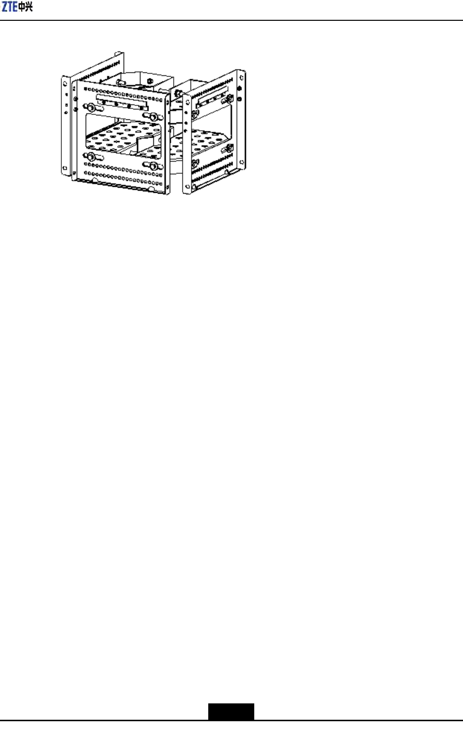
AppendixCOAU
FigureC-4FixingBracketAssemblies
Steps
1.Installtheanchorclampassembliesorthexingbracketassemblies.
Installtwosetsofanchorclampassembliesortwosetsofxingbracketsontothepole
andscrewdownabitwithbolts.TheanchorclampassembliesasshowninFigure
C-5andthexingbracketsareasshowninFigureC-6.
C-3
SJ-20100722143906-002|02/20/2011(R1.3)ZTEProprietaryandCondential
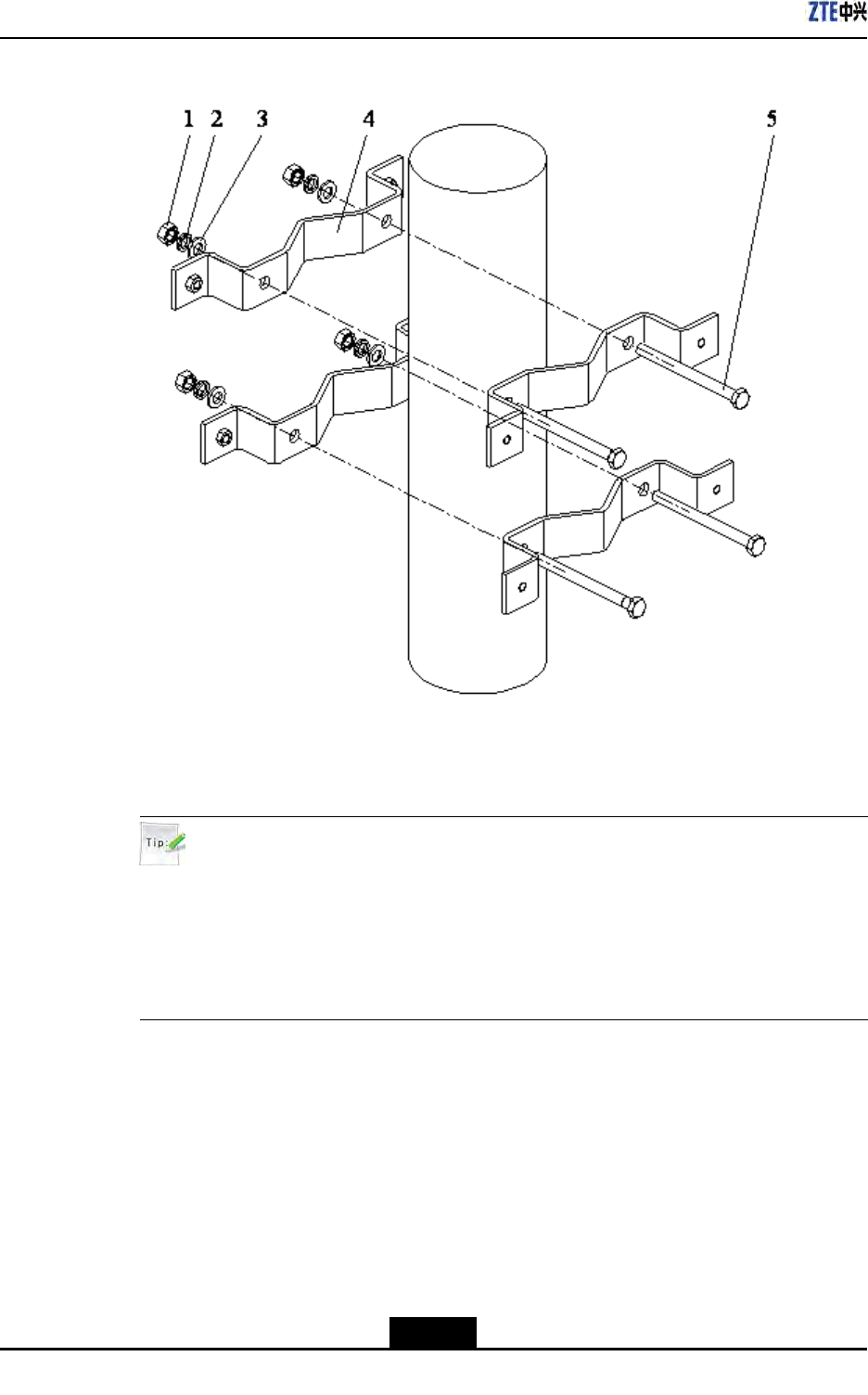
ZXSDRR8860InstallationManual
FigureC-5TwoSetsofAnchorClampAssemblies
1.I-typecommonM10
hexagonalnut
2.Standardspring
washer10
3.Flatwasher10
4.Longanchorclamp
5.M10×120hexagon
headbolt(fullthread)
Tip:
DuringtwoZXSDRR8860installation,thesuggestedpolediameteris60to120mm
andtherearetwokindsofboltlengths:
lUsetheboltoflength80mmforpolediameterof60mmto90mm.
lUsetheboltoflength120mmforpolediameterof90mmto120mm.
C-4
SJ-20100722143906-002|02/20/2011(R1.3)ZTEProprietaryandCondential
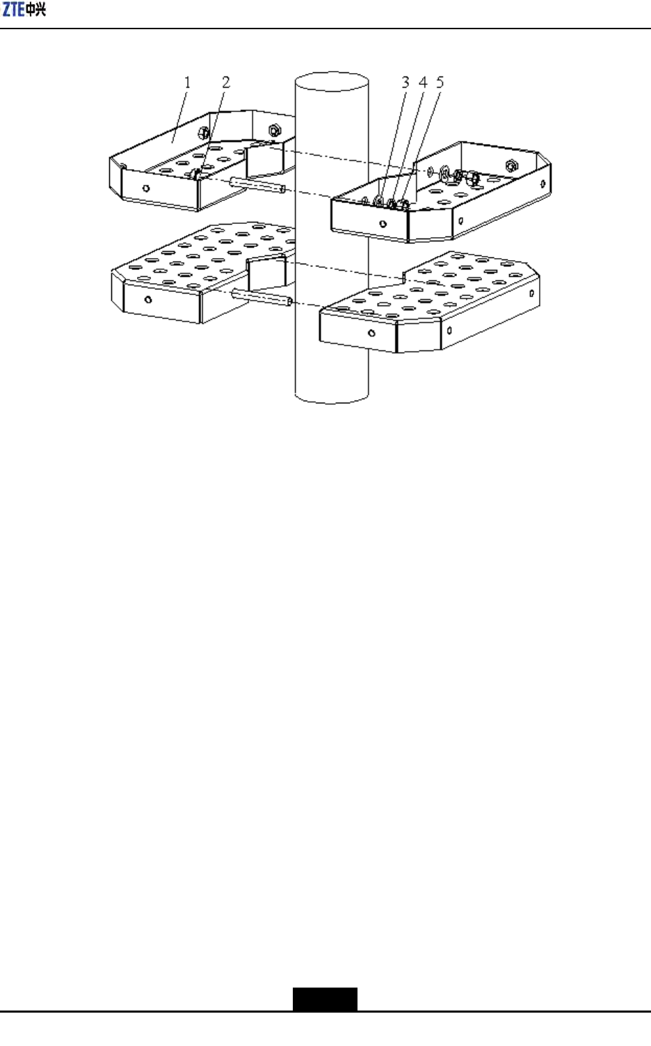
AppendixCOAU
FigureC-6TwoSetsofFixingBracketAssemblies
1.FixingBracket
2.M10×120hexagon
headbolt(fullthread)
3.Standardspring
washer10
4.Flatwasher10
5.I-typecommonM10
hexagonalnut
2.InstallthebracketofOAU.
ThebracketisasshowninFigureC-7.Installthebracketsontothepoleinsteadofthe
supportingpanelsasshowninFigureC-8andFigureC-9.Screwdownthebrackets.
C-5
SJ-20100722143906-002|02/20/2011(R1.3)ZTEProprietaryandCondential
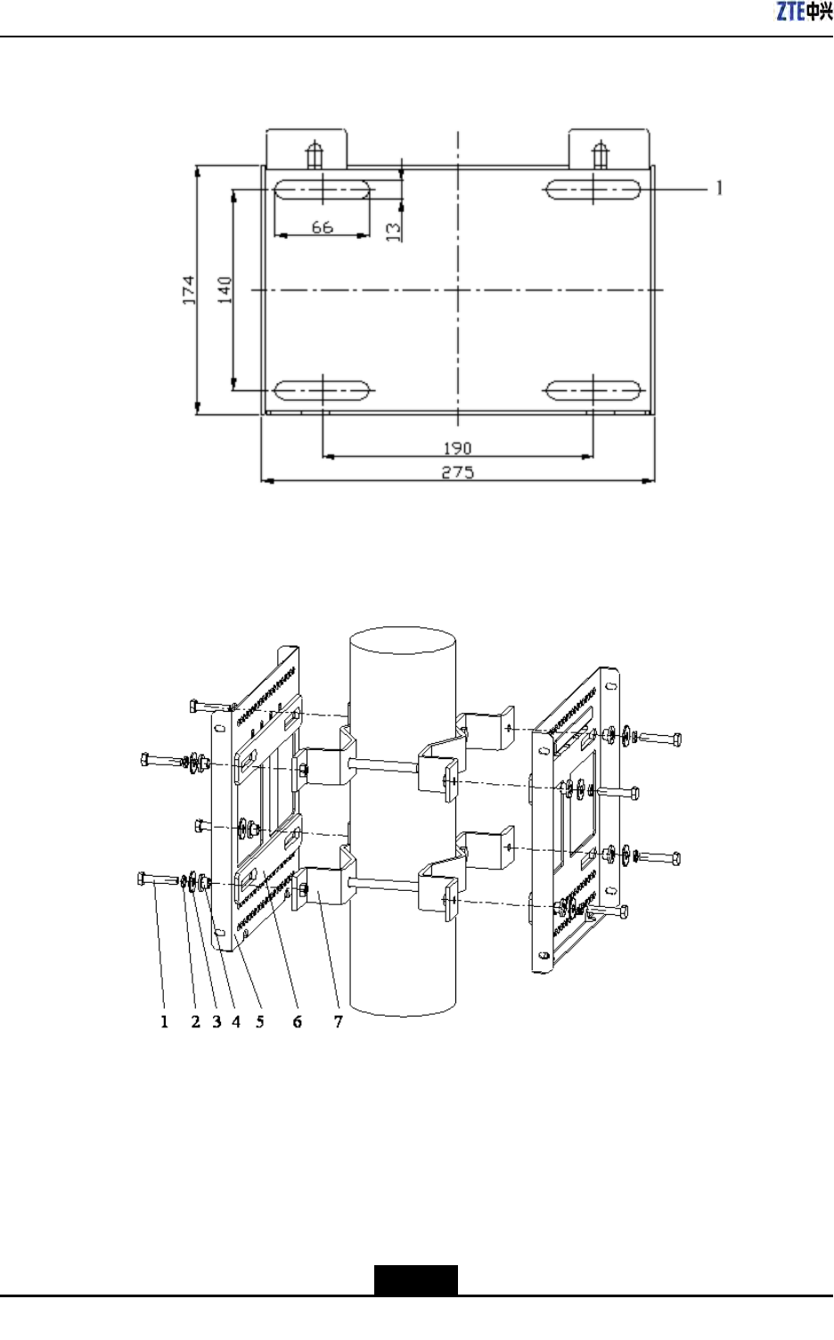
ZXSDRR8860InstallationManual
FigureC-7OAUBracket
1.Installationpole
FigureC-8TwoSetsofSupportingPanels
1.M8×40hexagonhead
bolt
2.Standardspring
washer8
3.Bigflatwasher8
4.Insulationflange
5.Supportingpanel
6.Insulationboard
7.Longanchorclamp
C-6
SJ-20100722143906-002|02/20/2011(R1.3)ZTEProprietaryandCondential
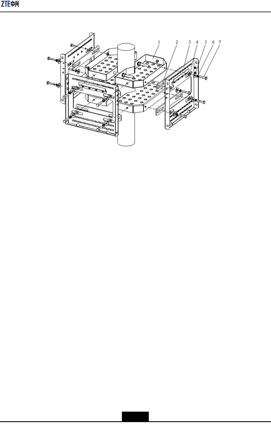
AppendixCOAU
FigureC-9ThreeSetsofSupportingPanels
1.Fixingbracket
2.Insulationboard
3.Supportingpanel
4.Insulationflange
5.Bigflatwasher8
6.Standardspring
washer8
7.M8×40hexagonhead
bolt
3.InstalltheOAU.
a.AsshownintheFigureC-10,fastentheOAUtothebracketswiththeM6hexagon
headscrewsaccordingtothearrowheaddirection.
C-7
SJ-20100722143906-002|02/20/2011(R1.3)ZTEProprietaryandCondential
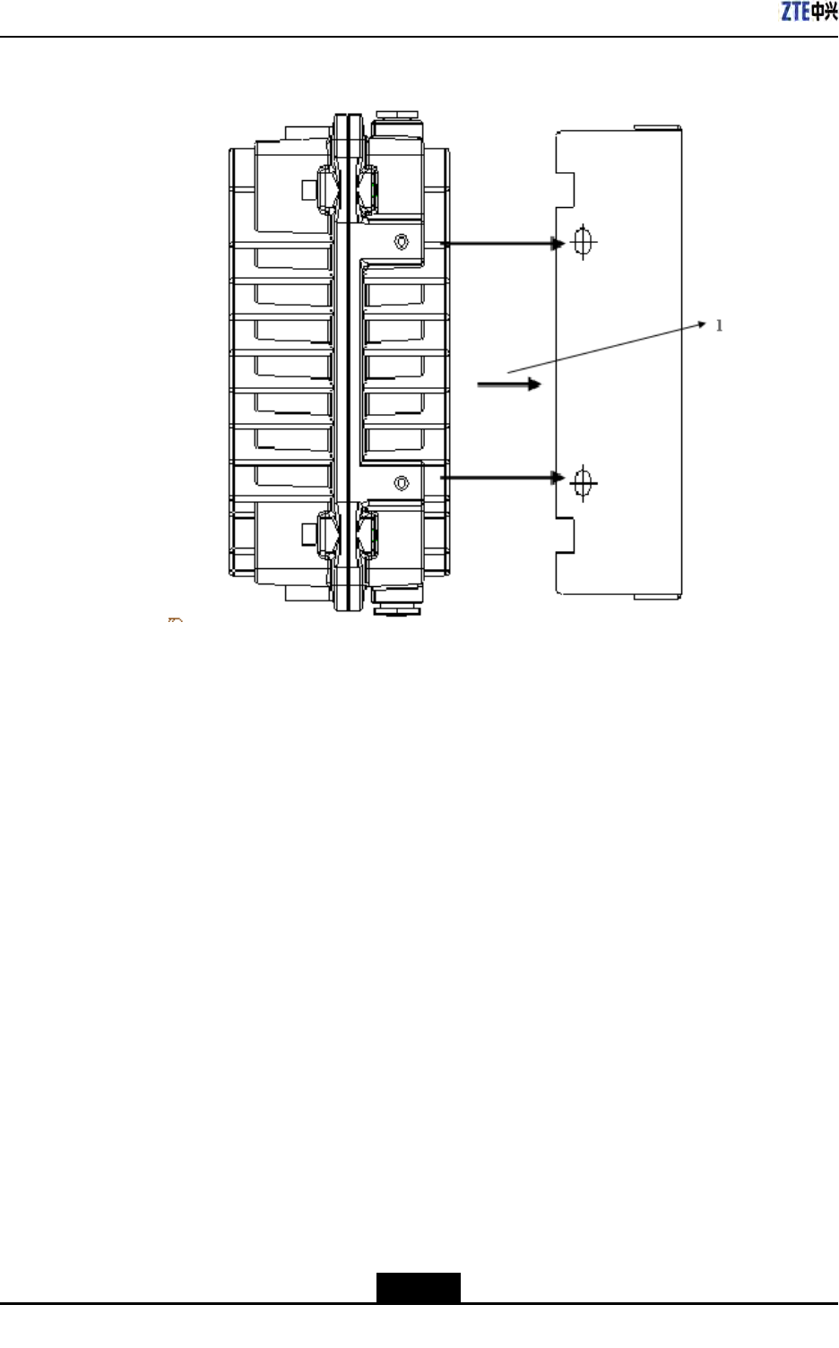
ZXSDRR8860InstallationManual
FigureC-10OAUInstallation(1)
1.Installation
direction
b.AsshownintheFigureC-11,connecttheOAU,atwasher,springwasherand
M8nutwiththeM8hexagonheadscrewsaccordingtothearrowheaddirection.
ScrewdowntheM8nutatthebackofbracketinordertofastentheOAUandthe
bracket.
C-8
SJ-20100722143906-002|02/20/2011(R1.3)ZTEProprietaryandCondential
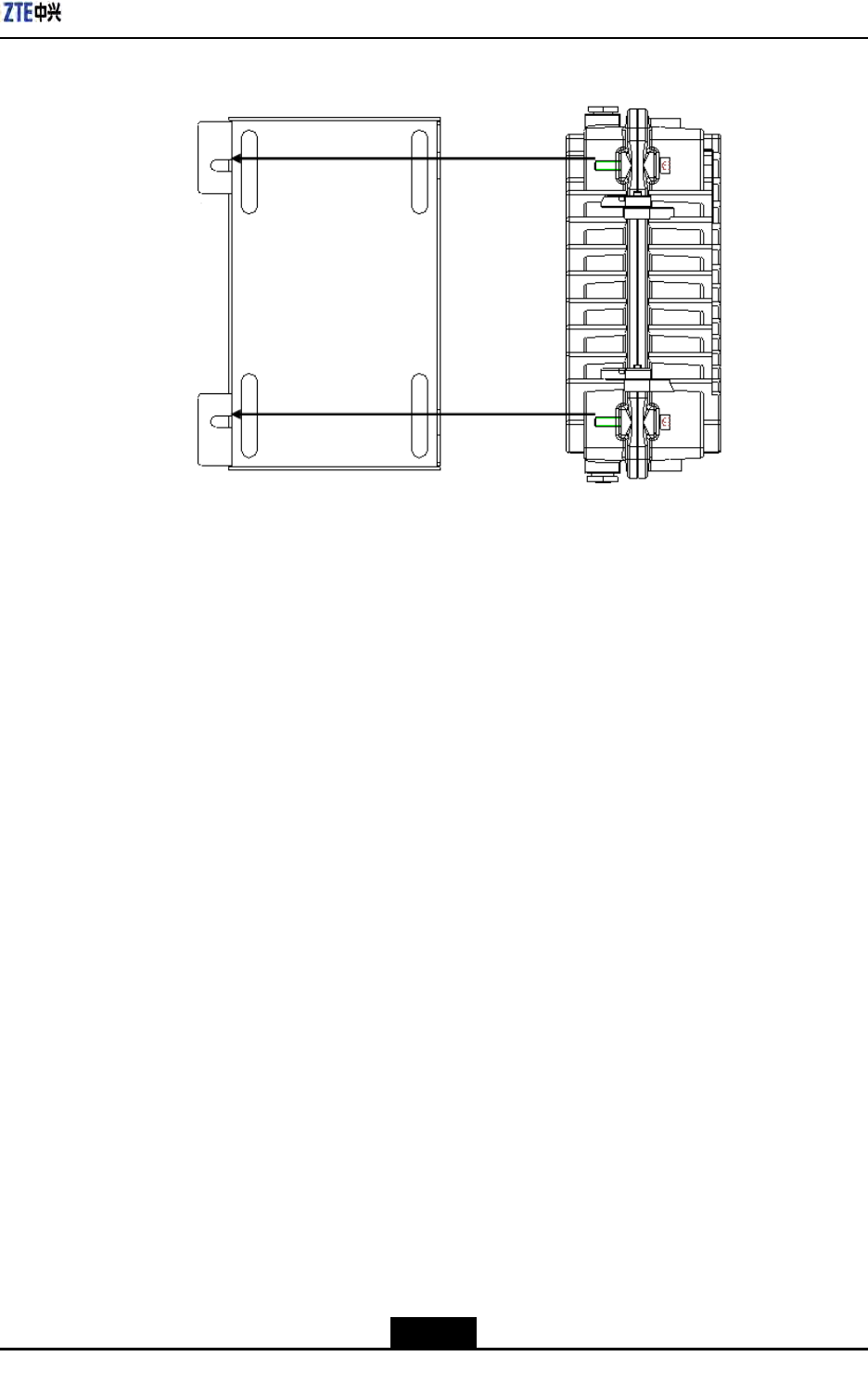
AppendixCOAU
FigureC-11OAUInstallation(2)
–EndofSteps–
C.3InstallationOAUinWall-mountMode
Prerequisites
UnpackingandacceptanceforoutdoorACunit(OAU)iseligible.
Steps
1.Installarack.
a.AsshownintheFigureC-12,drillholeswithM10drillonthewallandknockthe
M8expansionpipesintotheholes.Makesuretheexpansionboltserectedwith
thewall.
C-9
SJ-20100722143906-002|02/20/2011(R1.3)ZTEProprietaryandCondential
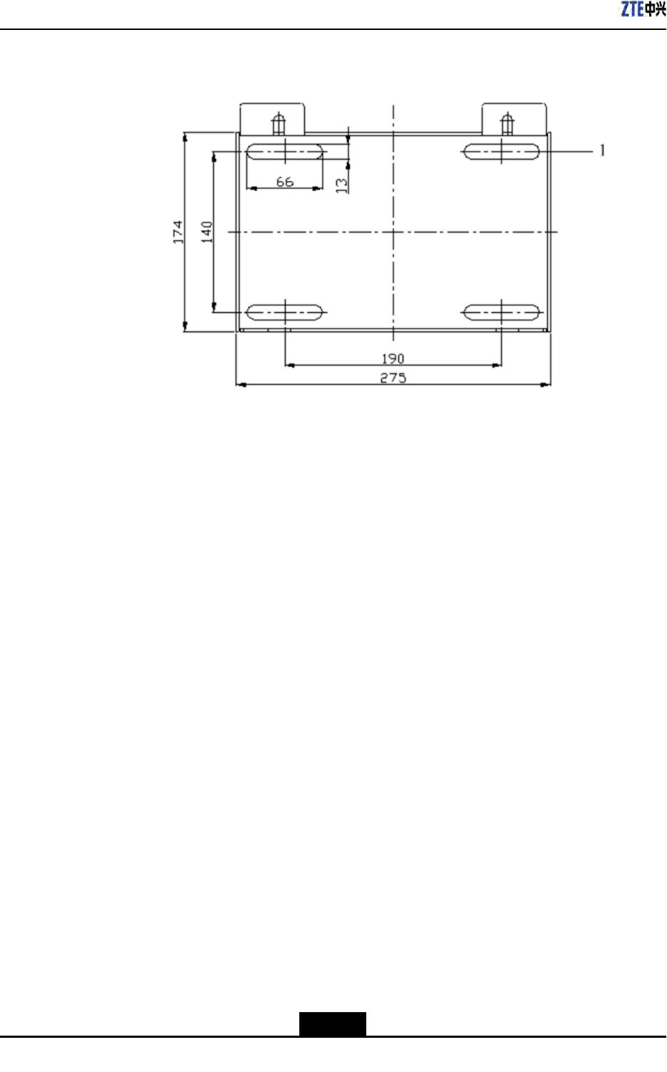
ZXSDRR8860InstallationManual
FigureC-12OAURack
1.Installationhole
b.Aligninstallationholesonthebrackettoextensionpipesonthewall.Afterhanging
thebracket,rotatetheself-drillingscrewassembledwithabigatwasheranda
springwasherintotheexpansionpipe.Screwdowntheboltwithawrench.
2.InstalltheOAU.
a.AsshownintheFigureC-13,fastentheOAUtothebracketswiththeM6hexagon
headscrewsaccordingtothearrowheaddirection.
C-10
SJ-20100722143906-002|02/20/2011(R1.3)ZTEProprietaryandCondential
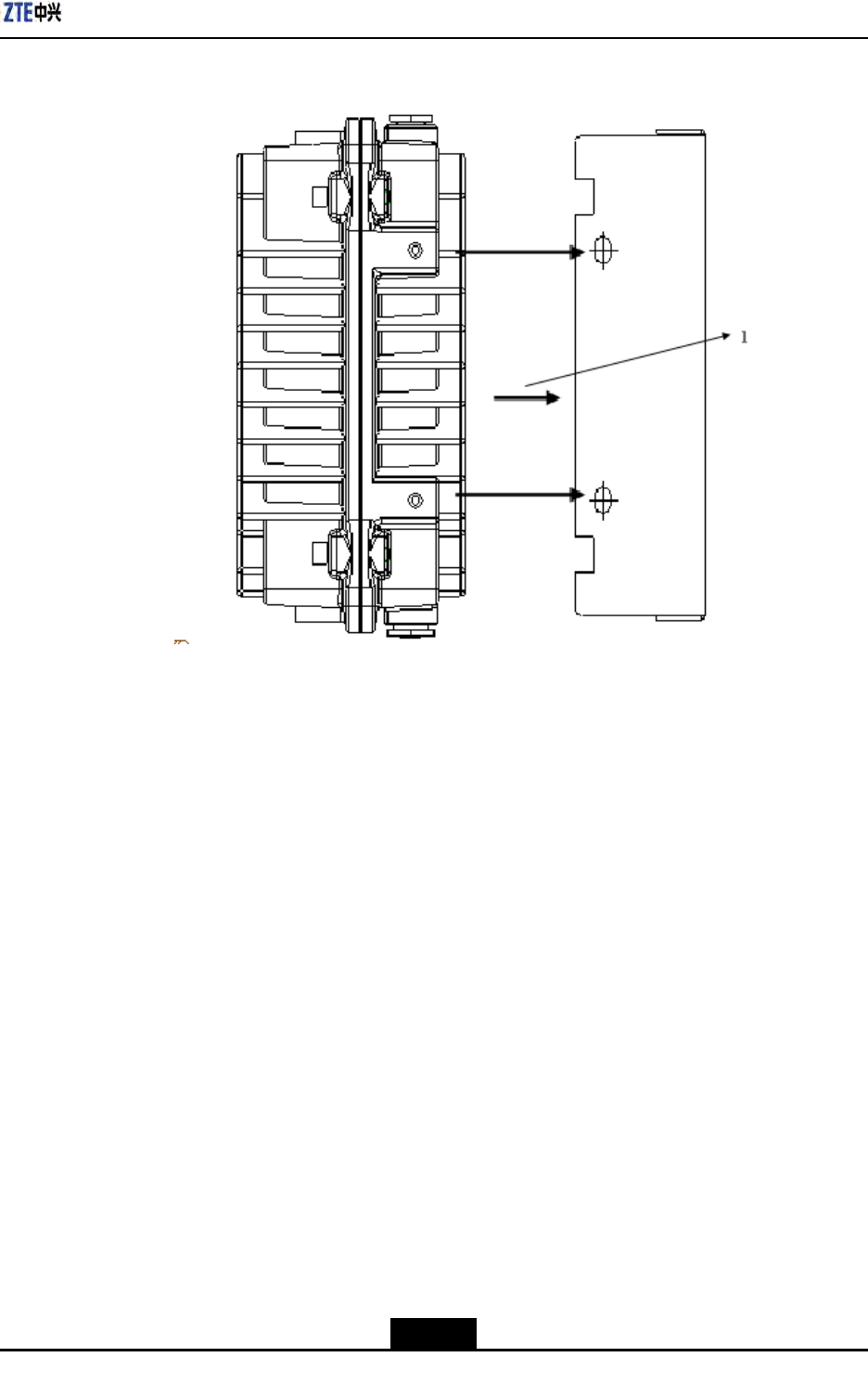
AppendixCOAU
FigureC-13OAUInstallation(1)
1.Installation
direction
b.AsshownintheFigureC-14,connecttheOAU,atwasher,springwasherand
M8nutwiththeM8hexagonheadscrewsaccordingtothearrowheaddirection.
ScrewdowntheM8nutatthebackofbracketinordertofastentheOAUandthe
bracket.
C-11
SJ-20100722143906-002|02/20/2011(R1.3)ZTEProprietaryandCondential
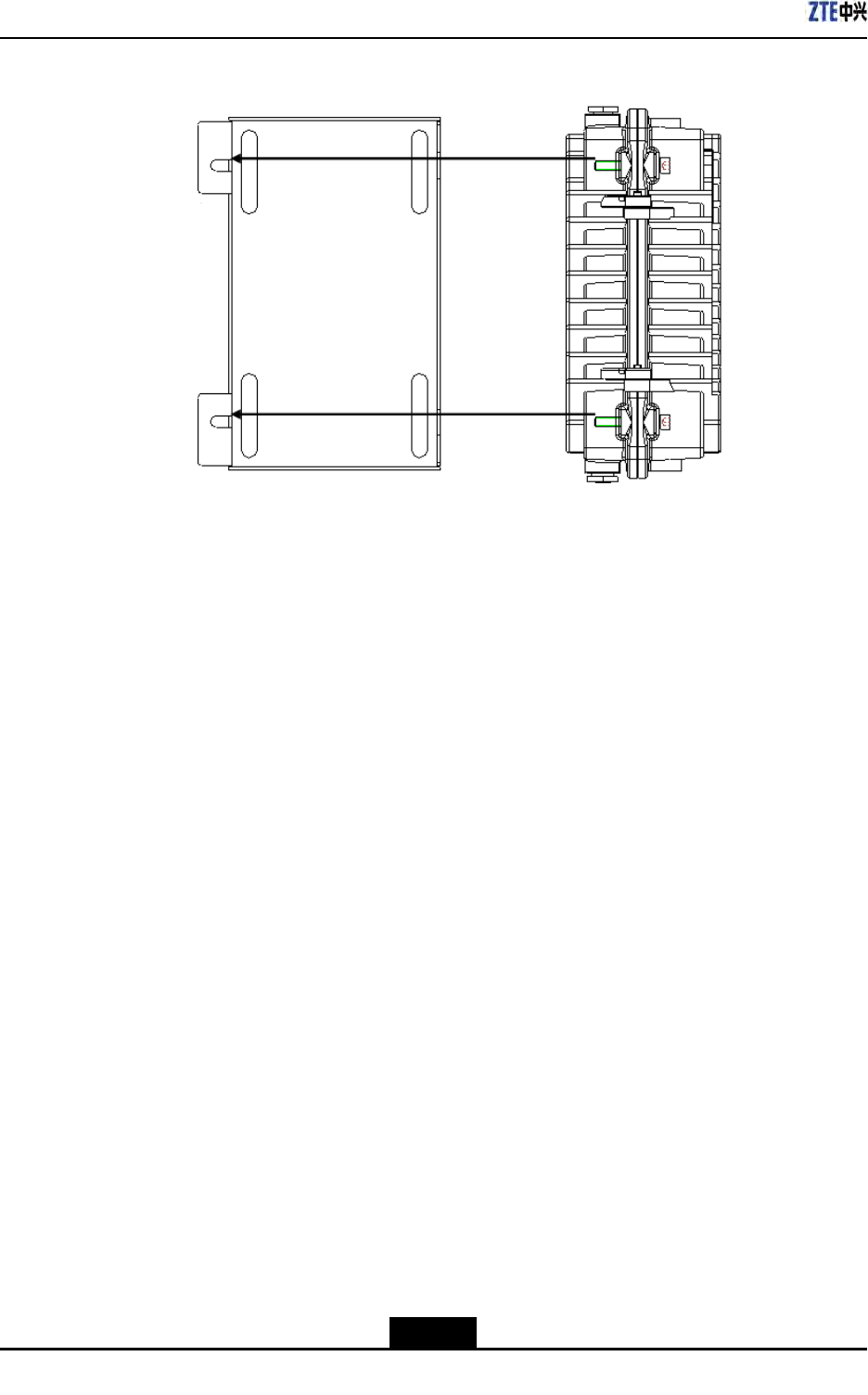
ZXSDRR8860InstallationManual
FigureC-14OAUInstallation(2)
–EndofSteps–
C.4InstallingOAUCable
Prerequisites
TheOAUinstallationiscompleted.
Context
TheOAUcanprovide-48VpowersupplyforoneZXSDRB8200C100andoneZXSDR
R8860atthesametime.
IftheOAUisinstalledoutsides,itisrequiredtocongureanAClightningbox.Forindoor
installation,iftheACpowercableisdistributedoutdoors,itisalsorequiredtocongurean
AClightningbox.
Steps
1.Installawaterproofendcap.
a.ReferringtotheFigureC-15andFigureC-16,loosenoffthewaterproofendcap.
C-12
SJ-20100722143906-002|02/20/2011(R1.3)ZTEProprietaryandCondential
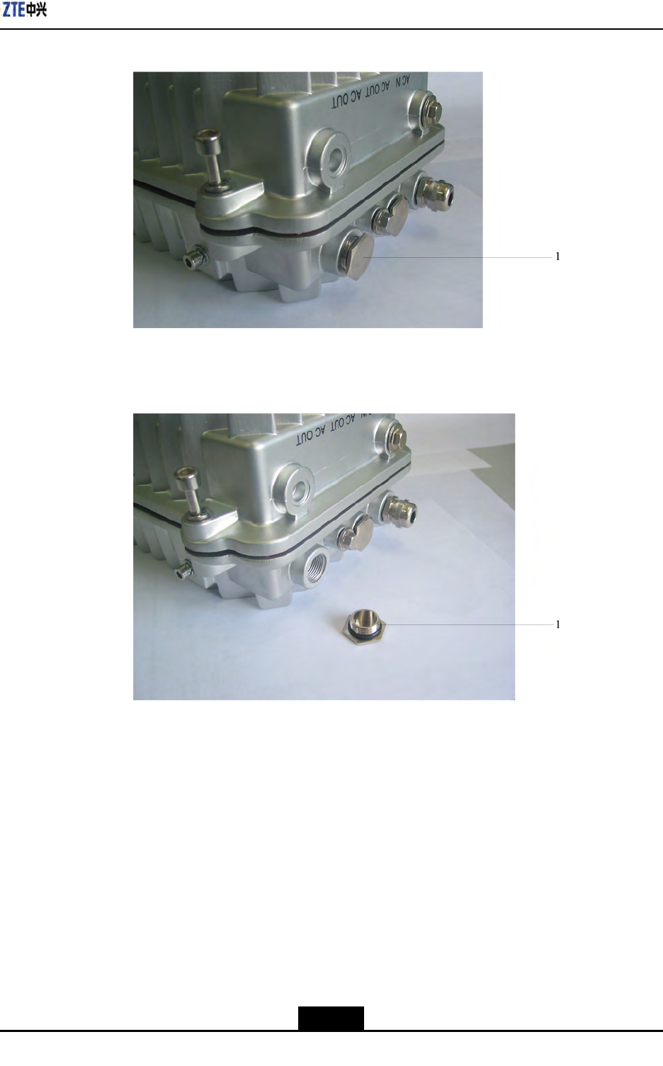
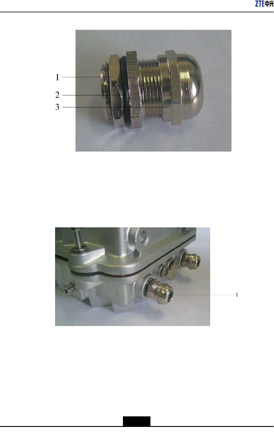
ZXSDRR8860InstallationManual
FigureC-17WaterproofEndCapStructure
1.Nut
2.Waterproofring
3.Waterproofend
cap
c.InstallthewaterproofendcapontotheOAUandscrewdownit,asshowninFigure
C-18.
FigureC-18WaterproofEndCapInstallation
1.Waterproofend
cap
2.DisassembletheOAUandconnecttheACpowercablewiththeDCpowercable.The
connectionofACcableisasshowninFigureC-19.
C-14
SJ-20100722143906-002|02/20/2011(R1.3)ZTEProprietaryandCondential
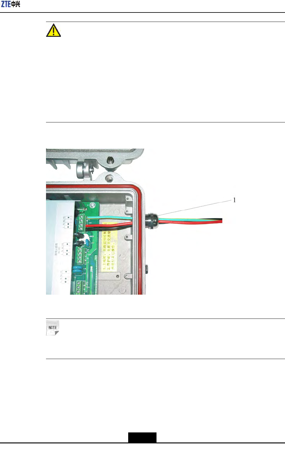
AppendixCOAU
Caution!
a.WhileconnectingtheACpowercable,rstconnectthePEcable,NcableandL
cable.Fordisconnecting,thesequenceisopposite,rsttheLcable,Ncableand
nallyPEcable.
b.Beforepoweron,rstconrmthePEcablegroundingwell.Duringmaintenance,
rstdisconnecttheACinputandthenperformotheroperation.
c.Aftercutoffthepower,waitforfourminutesatleastuntilthecapacitydischarge
enoughandthenperformmaintenanceoperationfortheOAU.
FigureC-19ACPowerCableConnection
1.Waterproofendcap
Note:
Thecablecolordecidesonsite.
3.ConnectoneAClightningbox,threeOAUsandthreeZXSDRR8860,asshownin
FigureC-20.FortheconnectionbetweenOAUandZXSDRB8200C100,pleaserefer
totheFigureC-20.
C-15
SJ-20100722143906-002|02/20/2011(R1.3)ZTEProprietaryandCondential
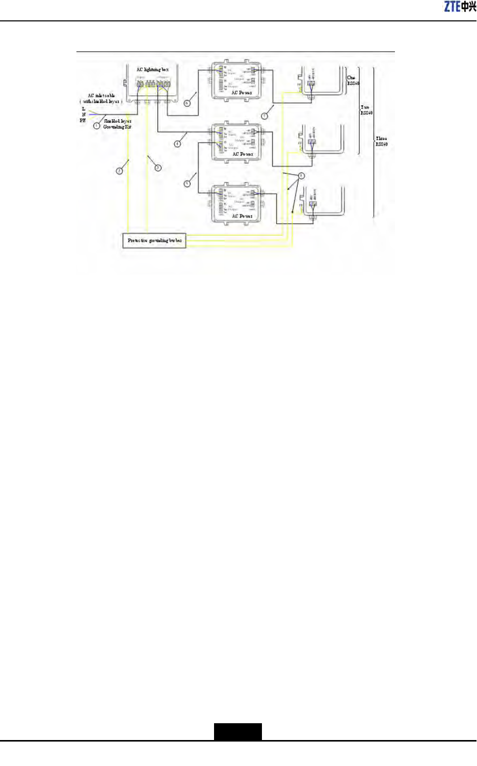
ZXSDRR8860InstallationManual
FigureC-20OneACLightningBox,ThreeOAUsandThreeR8860CableConnection
1.ACpowercable(For
outdoorinstallation,
three-coreoutdoor
aluminum-foil
shieldingpowercable;
forindoorinstallation,
PVCsheathpower
cable;thecablelength
dependsonsurveyon
site.)
2.Groundingcableof
groundingkit(with1.5
mlong)
3.Groundingcable
(yellow-and-green
fire-retardantcable;
thelengthislessthan
1m)
4.ACpowercable
(three-coreoutdoor
aluminum-foil
shieldingpowercable;
thecablelength
dependsonsurvey
onsite.)
5.ACpowercable
(three-coreoutdoor
aluminum-foil
shieldingpowercable;
thecablelength
dependsonsurvey
onsite.)
6.ACpowercable
(three-coreoutdoor
aluminum-foil
shieldingpowercable;
thecablelength
dependsonsurvey
onsite.)
7.DCpowercable
(four-core,with2
mlong)
8.Groundingcable
(yellow-and-green
fire-retardantcable;
thelengthislessthan
1m)
–EndofSteps–
C-16
SJ-20100722143906-002|02/20/2011(R1.3)ZTEProprietaryandCondential
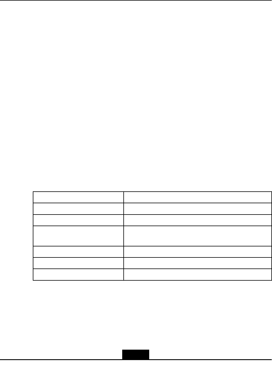
AppendixD
OLP48-2
TableofContents
ŸOLP48-2T echnicalIndices.....................................................................................D-1
ŸOLP48-2AppearanceandInterface........................................................................D-1
ŸOLP48-2InstallationDescription.............................................................................D-3
D.1OLP48-2TechnicalIndices
TheoutdoorDClightningbox(OLP48–2)isusedforsurgeprotectionofZXSDRR8860.
Thefollowingdescribesitscharacters:
lAdoptprotectivecircuitfortwoports,withlowresidualvoltageandgoodprotective
performance.
lAdoptthetemperature-controlbroken-circuittechnologytoavoidrehazards.
lAdoptpressure-sensitiveparallelconnectiontoenduresustaininglightningstrike.
lAdoptanalarmreportfunctionforremotemonitoring.
EngineeringTechnicalIndices
TableD-1describestheengineeringtechnicalindicesofoutdoorDClightningbox.
TableD-1EngineeringTechnicalIndices
ItemIndex
DimensionH×W×D:297mm×220mm×90mm
Nominalworkvoltage–48VDC
Maximumcontinuousrunning
voltage
–75VDC
Worktemperature-40℃+70℃
Workhumidity10%RH~95%RH25℃
Altitude≤3000m
D.2OLP48-2AppearanceandInterface
Appearance
FigureD-1showstheappearanceofoutdoorDClightningbox.
D-1
SJ-20100722143906-002|02/20/2011(R1.3)ZTEProprietaryandCondential
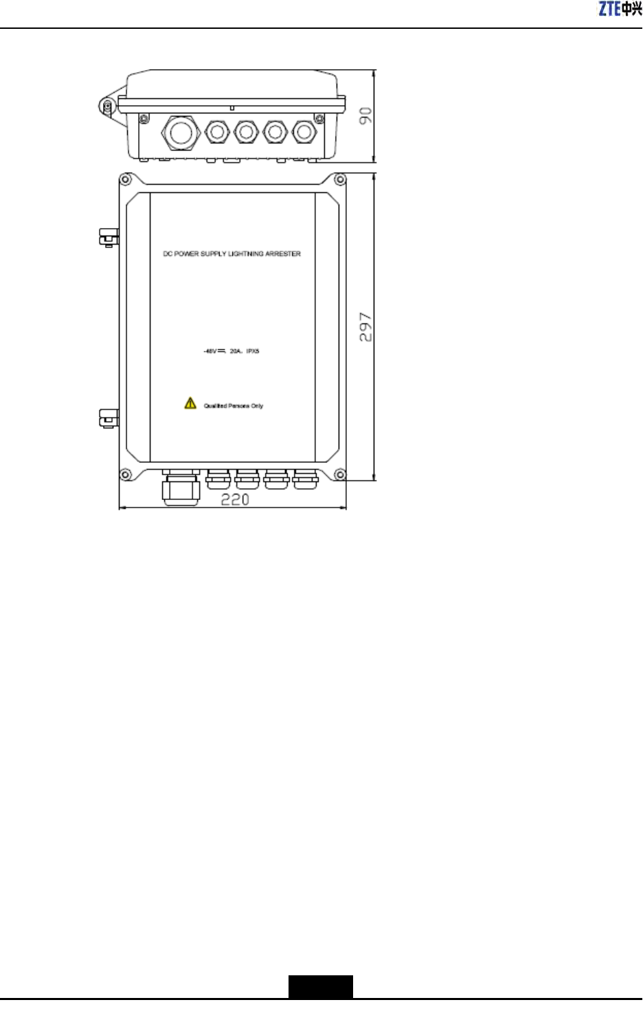
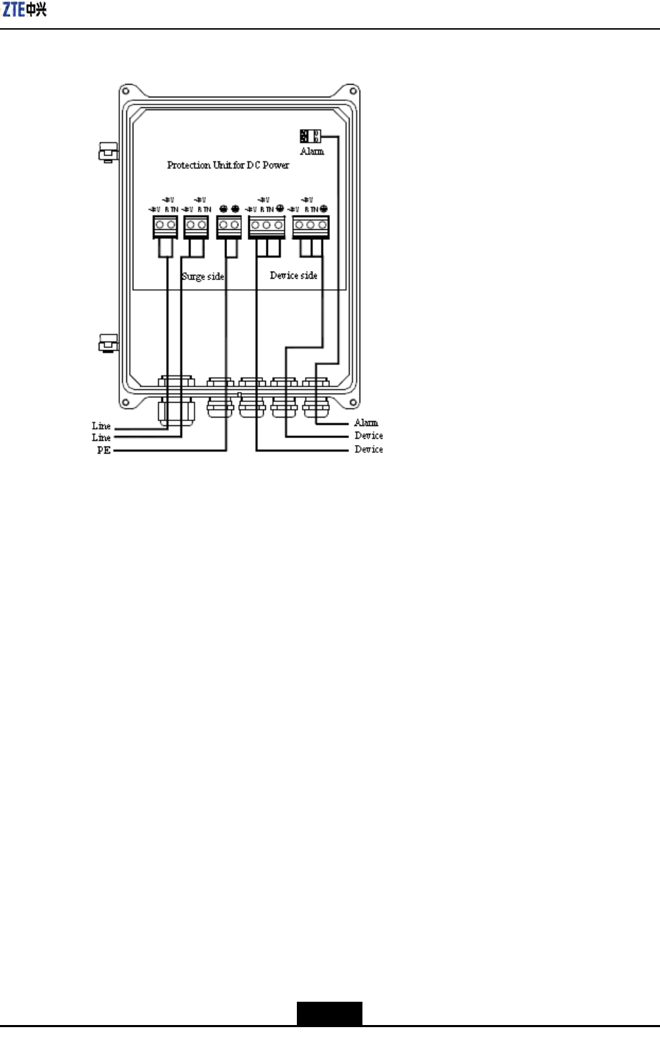
AppendixDOLP48-2
FigureD-2OutdoorDCLightningBoxInterface
D.3OLP48-2InstallationDescription
Installation
FigureD-3illustratespartstoprovideforpoleinstallationofoutdoorDClightningbox.
FigureD-4showstheappearanceafterinstallationcompletion.
D-3
SJ-20100722143906-002|02/20/2011(R1.3)ZTEProprietaryandCondential
ZXSDRR8860InstallationManual
FigureD-3InstallationParts
1.CombinedboltM4×10
2.Plainwasher8
3.Springwasher8
4.NutM8
5.OutdoorDClightningbox
6.OLPMsupport(1)
7.OLPMsupport(2)
8.HexagonboltM8×140
D-4
SJ-20100722143906-002|02/20/2011(R1.3)ZTEProprietaryandCondential
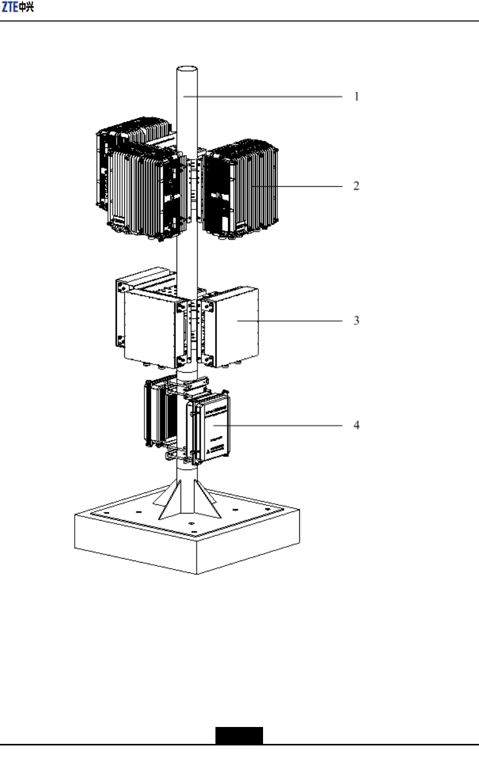
AppendixDOLP48-2
FigureD-4OutdoorDCLightningPoleInstallation
1.Pole
2.ZXSDRR8860
3.Wavetrap
4.OutdoorDClightningbox
CableConnection
TakeapartacabinetandconnectcablesasshowninFigureD-5.Connectoneoutdoor
DClightningboxwithone(ortwo)RRU,asshowninFigureD-6.
D-5
SJ-20100722143906-002|02/20/2011(R1.3)ZTEProprietaryandCondential
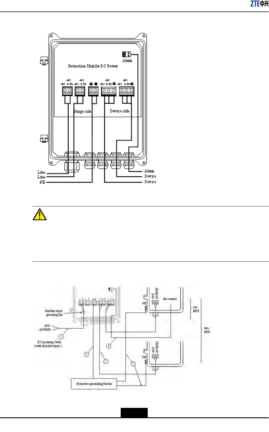
ZXSDRR8860InstallationManual
FigureD-5OutdoorDCLightningBoxInterfaces
Caution!
1.Whileconnectingcablesoflightningbox,itisrequiredtoputthecablethroughthe
holeofwaterproofconnectoratthebottomofbox.
2.Firstconnectthegroundcablesandthenconnectothercables.Whiledisconnecting,
nallyremovethegroundcable.
FigureD-6OutdoorDCLightningConnection
1.DCpowercable(two-core
outdoorshieldedpower
cable;theshieldedlayer
isgroundinginsidethe
lightingbox;thecable
D-6
SJ-20100722143906-002|02/20/2011(R1.3)ZTEProprietaryandCondential

AppendixDOLP48-2
lengthdependsonthe
on-sitesurvey)
2.Groundingcable
(yellow-and-green
fire-retardantcable;the
lengthislessthan1m)
3.DCpowercable(four-core
with2mlong)
4.Datacable(eight-pair
twisted-pairoutdoordata
cablewith3mlong)
5.Groundingcable
(yellow-and-green
fire-retardantcable;the
lengthislessthan1.5m)
D-7
SJ-20100722143906-002|02/20/2011(R1.3)ZTEProprietaryandCondential

ZXSDRR8860InstallationManual
Thispageintentionallyleftblank.
D-8
SJ-20100722143906-002|02/20/2011(R1.3)ZTEProprietaryandCondential
AppendixE
ILP48-3
TableofContents
ŸILP48-3T echnicalIndices.......................................................................................E-1
ŸILP48-3AppearanceandInterface.........................................................................E-2
ŸILP48-3InstallationDescription..............................................................................E-3
E.1ILP48-3TechnicalIndices
ForZXSDRR8860outdoorinstallation,iftheDCpowerisexportedfromtheequipment
roomandtheoutputportofindoorDCpowerisnotconguredwithaB-levelorabove
lightningdevices,itisrequiredtoinstallanindoorDClightingbox(ILP48–3)atthesideof
equipmentroom.
TheindoorDClightningboxcontainsthreeindividualDC-48VDClightnings.Their
charactersaredescribedasfollows:
1.Adoptthetemperature-controlbroken-circuittechnologytoavoidrehazards.
2.Adoptanalarmreportfunctionforremotemonitoring.
3.Adoptdouble-colorindicatorstodirectlyandclearlyindicateworkingstatus
EngineeringTechnicalIndices
TableE-1describestheengineeringtechnicalindicesofindoorDClightningbox.
TableE-1EngineeringTechnicalIndices
ItemIndex
DimensionH×W×D:450mm×400mm×100mm(notincludetheheightof
lockontheuppercover)
Nominalworkvoltage–48VDC
Maximumcontinuousrunning
voltage
–75VDC
Worktemperature-5℃+70℃
Workhumidity≤95%RH
E-1
SJ-20100722143906-002|02/20/2011(R1.3)ZTEProprietaryandCondential
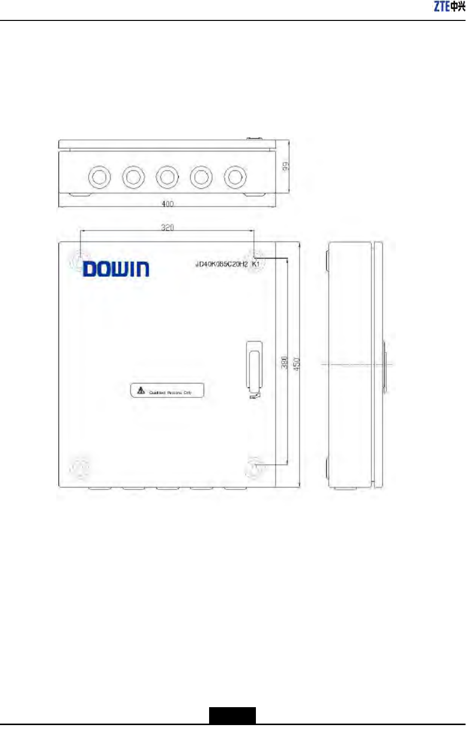
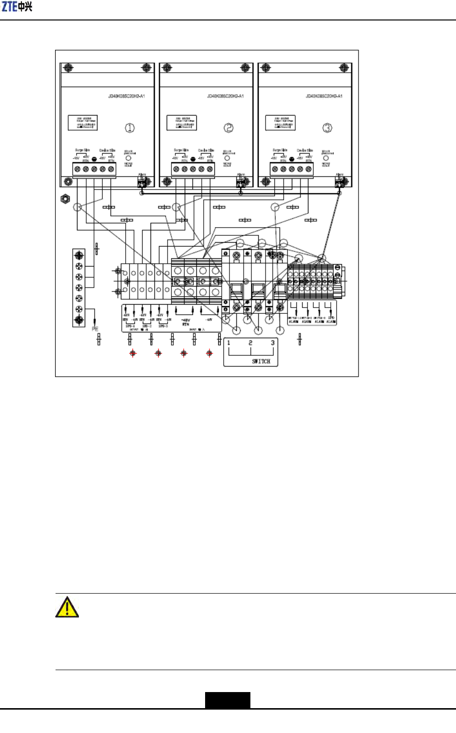
AppendixEILP48-3
FigureE-2IndoorDCLightningBoxInterfaces
E.3ILP48-3InstallationDescription
Installation
TheindoorDClightingboxadoptsanon-wallinstallationmode.Drillholeonthewallof
equipmentroomaccordingtoinstallationpolepositionsonthelightningbox.Selectfour
M6×60(ormorelonger)expansionboltstofastenthelightningboxonthewall.
CableConnection
FigureE-3illustratescableconnectionoflightningbox.
Caution!
Firstconnectthegroundingcableandthenothercables.Whiledisconnecting,nally
removethegroundingcable.
E-3
SJ-20100722143906-002|02/20/2011(R1.3)ZTEProprietaryandCondential
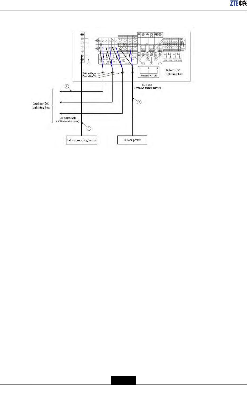
ZXSDRR8860InstallationManual
FigureE-3IndoorDCLightningBoxCableConnection(notconnectwithremotealarm)
1.DCpowercable(two-core
outdoorshieldedpower
cable;theshieldedlayer
isgroundinginsidethe
lightingbox;thecable
lengthdependsonthe
on-sitesurvey)
2.DCpowercable(two-core
outdoorshieldedpower
cable;thecablelength
dependsontheon-site
survey)
3.Groundingcable
(yellow-and-green
fire-retardantcable;the
lengthislessthan1.5m)
E-4
SJ-20100722143906-002|02/20/2011(R1.3)ZTEProprietaryandCondential

AppendixF
ACLightningArrester
TableofContents
ŸACLightningT echnicalIndices...............................................................................F-1
ŸACLightningAppearanceandInterface.................................................................F-2
ŸACLightningInstallationDescription.......................................................................F-3
ŸInstallingShieldedGroundingKit...........................................................................F-7
F.1ACLightningTechnicalIndices
TheprotectivecircuitofAClightningconsistsofpowerprotectionandsignalprotection,
respectivelyusedforlightningsurgeprotectionofsupplypowerandcircuitinterface.
Thecharactersofpowerprotectionaredescribedasfollows:
lAdoptseriesprotectivecircuit,withlowresidualvoltageandgoodprotective
performance.
lAdoptthetemperature-controlbroken-circuittechnologytoavoidrehazards.
lAdoptpressure-sensitiveparallelconnectiontoenduresustaininglightningstrike.
Thecharactersofsignalprotectionaredescribedasfollows:
lLargedischargecurrent
lLowresidualvoltageandgoodprotectiveperformance
lEightsignalprotectioncircuits
EngineeringTechnicalIndices
TableF-1describestheengineeringtechnicalindicesofAClightningbox.
TableF-1EngineeringTechnicalIndices
ItemIndex
DimensionH×W×D:297mm×220mm×90mm
Ratingworkvoltage110/220~240VAC50/60Hz
Maximumcontinuousrunning
voltage
385VAC
Worktemperature-40℃+70℃
Workhumidity10%RH~95%RH25℃
Altitude≤3000m
F-1
SJ-20100722143906-002|02/20/2011(R1.3)ZTEProprietaryandCondential
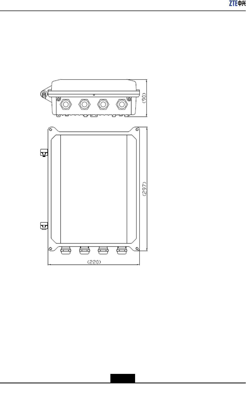
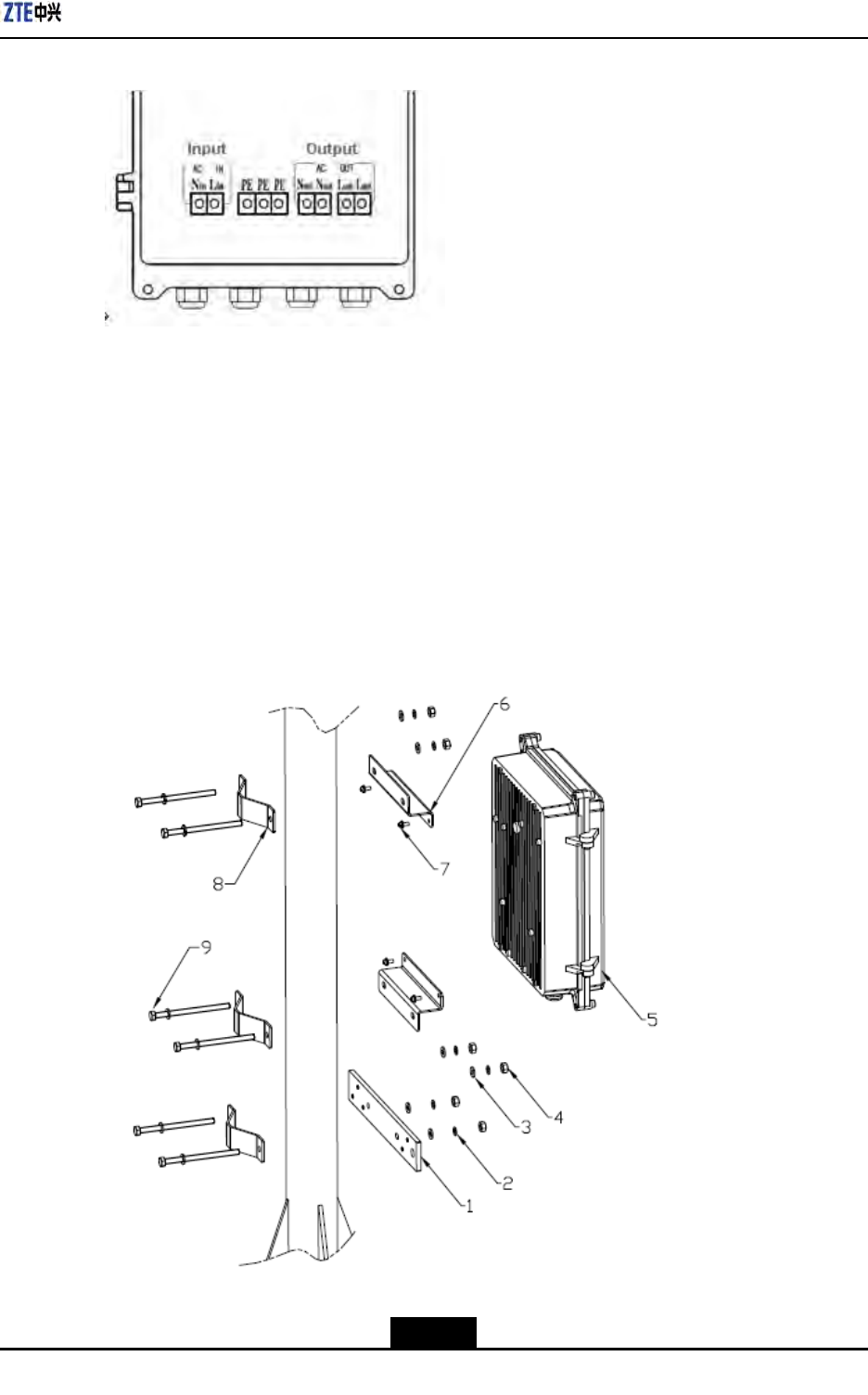
AppendixFACLightningArrester
FigureF-2ACLightningBoxInterface
F.3ACLightningInstallationDescription
WhentheZXSDRR8860isinstalledoutsides,itisrequiredtocongureAClightningboxfor
ACpowersupply.WhentheZXSDRR8860isinstalledoutsides,itisrequiredtocongure
AClightningboxatthefrontofoutdoorACunit(OAU)forindirectACpowersupply.
Installation
FigureF-3illustratespartstoprovideforpoleinstallationofAClightningbox.FigureF-4
showstheappearanceafterinstallationcompletion.
FigureF-3ACLightningBoxInstallationParts
1.Groundingcopperbar2.SpringwasherM63.FlatwasherM6
F-3
SJ-20100722143906-002|02/20/2011(R1.3)ZTEProprietaryandCondential
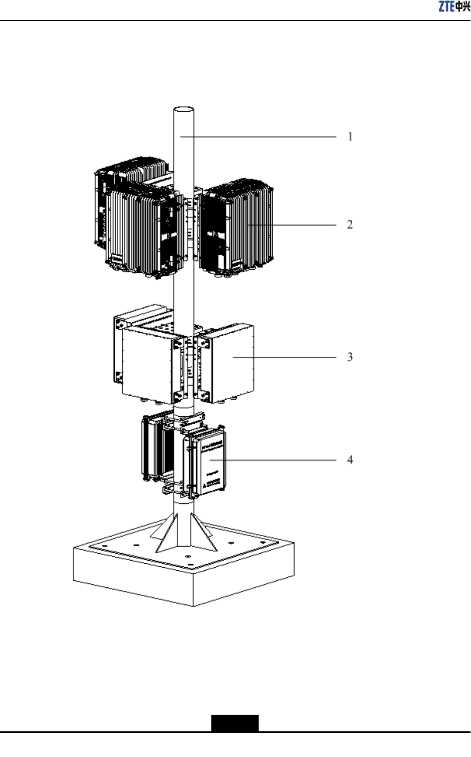
ZXSDRR8860InstallationManual
4.NutM6
5.AClightningbox
6.Installationsupport
7.CombinedboltM4×10
8.Fastener
FigureF-4ACLightningPoleInstallation
1.Pole
2.ZXSDRR8860
3.Wavetrap
4.AClightningbox
CableConnection
Unpackacabinetandconnectcables.
F-4
SJ-20100722143906-002|02/20/2011(R1.3)ZTEProprietaryandCondential
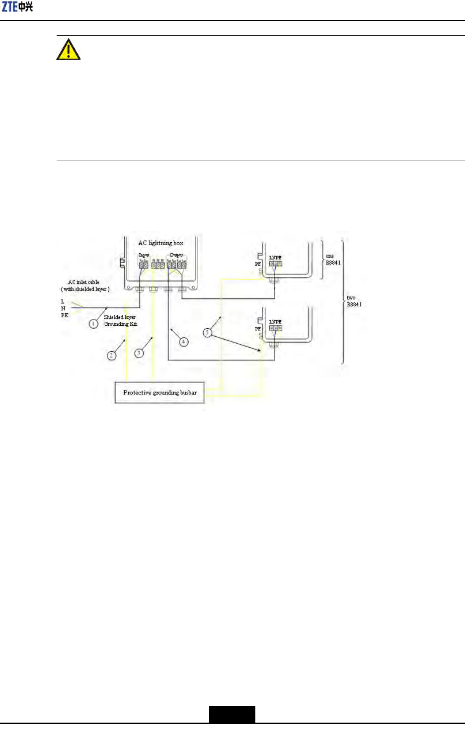
AppendixFACLightningArrester
Caution!
1.Firstconnectthegroundingcableandthenothercables.Whiledisconnecting,nally
removethegroundingcable.
2.Thecabletoconnectthelightningboxmustbeputthroughaholeofwaterproof
connectoratthebottomofbox.
3.Afterconnectioncompletedandchecked,screwdownallwaterproofconnectorsand
wrapwaterproofconnectorsandcableswithwaterproofadhesivetape.
ConnectoneAClightningboxwithone(ortwo)ZXSDRR8841,asshowninFigureF-5.
FigureF-5OneACLightningBoxandOne(ortwo)R8841CableConnection
1.ACpowercable(three-core
outdoorbraidandaluminum
foilshieldingcable;the
cablelengthdependson
on-sitesurvey)
2.Groundingkitgrounding
cable(two-corepower
cablewith1.5mlong)
3.Groundingcable
(yellow-and-green
fire-retardantcable;the
lengthislessthan1.5m)
4.ACpowercable(softcable
andthelengthdependson
on-sitesurvey)
5.Groundingcable
(yellow-and-green
fire-retardantcable;the
lengthislessthan1.5m)
ConnecttwoAClightningboxwiththreeZXSDRR8841,asshowninFigureF-6.
F-5
SJ-20100722143906-002|02/20/2011(R1.3)ZTEProprietaryandCondential
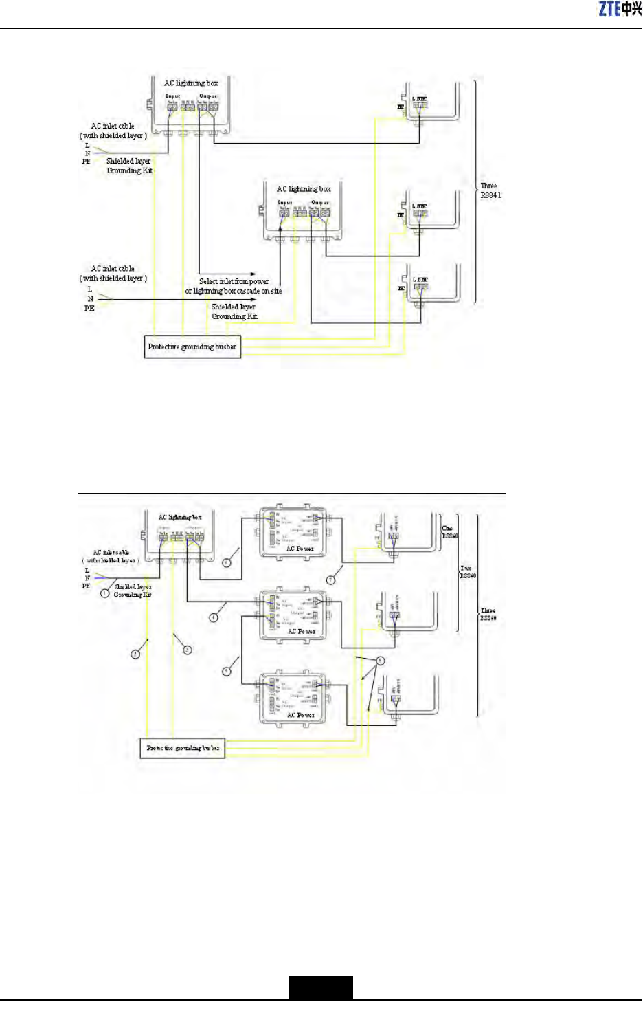
ZXSDRR8860InstallationManual
FigureF-6TwoACLightningBoxandThreeR8841CableConnection
•CabletypereferstoFigure
F-6.
ConnectoneAClightningbox,threeOAUswiththreeR8860,asshowninFigureF-7.
FigureF-7OneACLightningBox,ThreeOAUsandThreeR8860CableConnection
1.ACpowercable(For
outdoorinstallation,
three-coreoutdoor
aluminum-foilshielding
powercable;forindoor
installation,PVCsheath
powercable;thecable
lengthdependsonsurvey
onsite.)
2.Groundingcableof
groundingkit(with1.5
mlong)
3.Groundingcable
(yellow-and-green
fire-retardantcable;the
lengthislessthan1m)
4.ACpowercable(three-core
outdooraluminum-foil
shieldingpowercable;the
cablelengthdependson
surveyonsite.)
5.ACpowercable(three-core
outdooraluminum-foil
shieldingpowercable;the
cablelengthdependson
surveyonsite.)
6.ACpowercable(three-core
outdooraluminum-foil
shieldingpowercable;the
cablelengthdependson
surveyonsite.)
7.DCpowercable(four-core,
with2mlong)
8.Groundingcable
(yellow-and-green
F-6
SJ-20100722143906-002|02/20/2011(R1.3)ZTEProprietaryandCondential
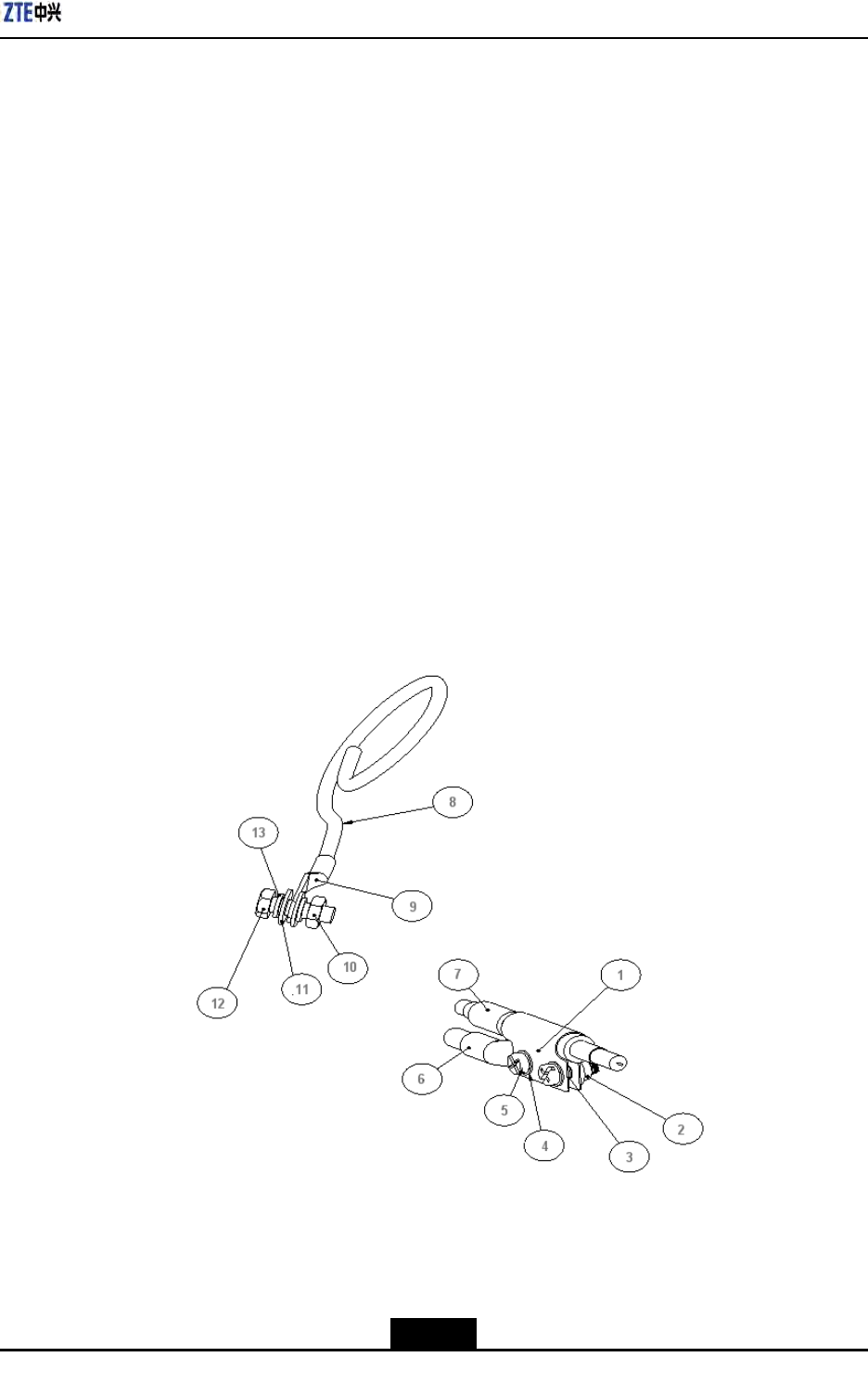
AppendixFACLightningArrester
fire-retardantcable;the
lengthislessthan1m)
F.4InstallingShieldedGroundingKit
Prerequisites
Theshieldedpowercableisinstalled.
Context
ThissectoronlydescribesinstallationofshieldedgroundingkitofAClightningbox'spower
cable.
Steps
1.Selectaproperinstallationpositionforgroundingkit.Selectanappropriategrounding
kitaccordingtodiameterofpowercable.Cutoffsheathofpowercableandxthe
shieldedlayerofpowercablewithagroundingkit.Thestructureofgroundingkitis
asshowninFigureF-8.FigureF-9andFigureF-10illustratevariousgroundingkits
adoptedfordifferentdiameters.
FigureF-8ShieldedGroundingKitStructure
1.Groundingkitbody
2.Squeezescrew
3.O–typering4
4.Flatwasher4
5.Buttonheadedscrew
M4×12
6.Connectingterminal
(dual-hole)
7.Shieldedpowercable
8.Groundingcable
9.Groundingterminal
(singlehole)
10.Hexagonnut8
11.Flatwasher8
12.HexagonboltM8×25
13.Springwasher8
F-7
SJ-20100722143906-002|02/20/2011(R1.3)ZTEProprietaryandCondential
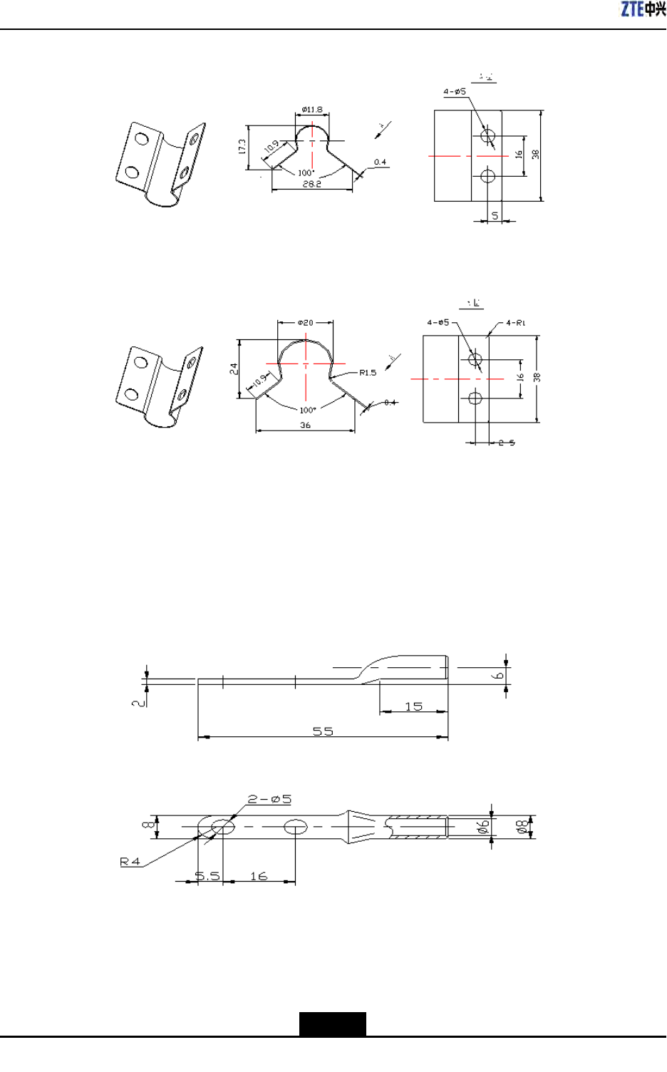
ZXSDRR8860InstallationManual
FigureF-9GroundingBody1(adoptablefor6mm2two-coreoutdoorpowercable)
FigureF-10GroundingBody2(adoptablefor16mm2two-coreoutdoorpowercable)
2.Screwdownthedual-holeconnectingterminaltoxonthebodyofgroundingkit.
Connecttheconnectingterminalwiththegroundingcable.Protectthejunction
betweengroundingcableandconnectingterminalwiththermoplasticsleeve.Pullthe
groundingcabletowardsthegroundgrid.Thedual-holeconnectingterminalisas
showninFigureF-11.
FigureF-11ConnectingTerminal(dual-hole)
3.Performwaterproofprocessingforthejunctionbetweengroundingkitandpowercable.
Themethodsaredescribedasfollows:
a.Wrapwaterproofself-adhesivetapeandthenwrapPVCadhesivetape.
F-8
SJ-20100722143906-002|02/20/2011(R1.3)ZTEProprietaryandCondential
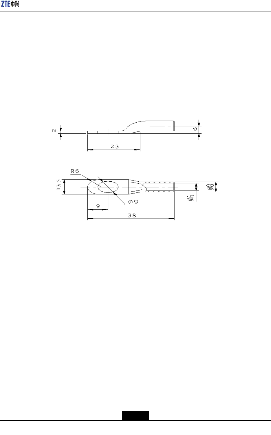
AppendixFACLightningArrester
b.Whilewrappingwaterproofself-adhesivetape,rstwraplayerbylayerfromdown
toup,thenfromuptodownandnallyfromdowntoupagain.Theupperlayer
shouldcoverhalfofthelowerlayer.
4.Fastenthesingle-holeconnectingterminalattheotherendofgroundingcabletothe
groundingbarwithM8×25hexagonbolts.Cleanawaypaintandoxidwithin13mm
radiusofconnectingposition,andcoverantioxidationpasteonittomakesuregood
electricalcontact.Afterconnectioncompleted,coveralayerofantirustpaint.The
single-holeconnectingterminalisasshowninFigureF-12.
FigureF-12ConnectingTerminal(single-hole)
–EndofSteps–
F-9
SJ-20100722143906-002|02/20/2011(R1.3)ZTEProprietaryandCondential

ZXSDRR8860InstallationManual
Thispageintentionallyleftblank.
F-10
SJ-20100722143906-002|02/20/2011(R1.3)ZTEProprietaryandCondential
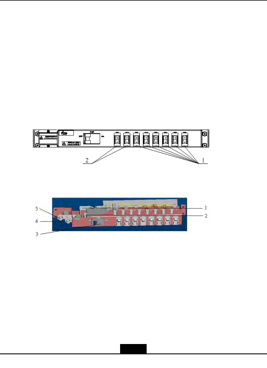
AppendixG
PDM
TableofContents
ŸPDMAppearanceandInterface..............................................................................G-1
ŸInstallingPDM........................................................................................................G-1
G.1PDMAppearanceandInterface
Powerdistributionmodule(PDM)isinstalledinasimpliedcabinettotransferDCpower
forZXSDRR8860.PoweronoroffasingleZXSDRR8860bycontrolofswitchesonthe
PDM.
FigureG-1andFigureG-2illustratetheappearanceandinterfacesofPDM.
FigureG-1PowerDistributionBoxPlane
1.BBUpowerswitch2.RRUpowerswitch
FigureG-2PowerDistributionBox
1.–48VGNDoutputcopper
bar
2.–48Voutputcopperbar
3.Powermainswitch
4.–48V
5.–48VGND
G.2InstallingPDM
Context
Thepowerdistributionmodule(PDM)isinstalledinanintegrativecabinettotransferDC
powerforZXSDRB8200C100,ZXSDRR8841orZXSDRR8860.
G-1
SJ-20100722143906-002|02/20/2011(R1.3)ZTEProprietaryandCondential
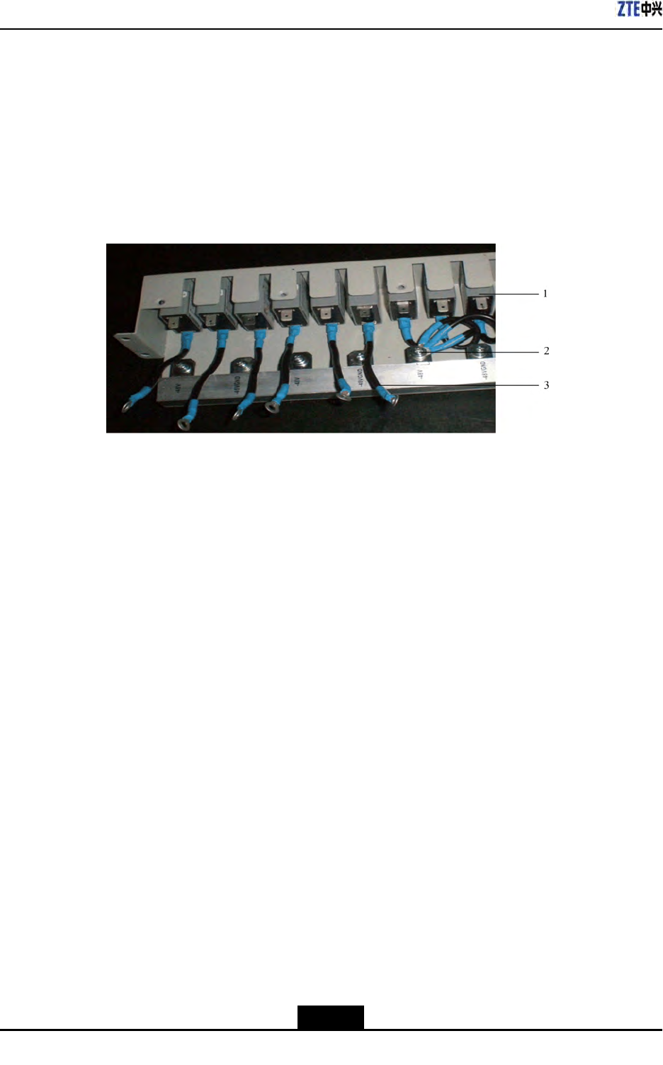
ZXSDRR8860InstallationManual
Steps
1.Checkinstallationofpowerswitches.ThestatusofONandOFFshouldbeconsistent
withsilkscreensonthePDMswitchplane.
2.Connectinternalcables.
ConnectanendofinternalcabletotheOFFendofpowerswitchesandwrapadhesive
tape,asshowninFigureG-3.
FigureG-3InsideCabletoconnectwithPDM
1.Powerswitch2.Connectingterminal3.Internalcable
3.InstallthePDMconnectedwithinternalcablestothesimpliedcabinet,asshownin
FigureG-4.
G-2
SJ-20100722143906-002|02/20/2011(R1.3)ZTEProprietaryandCondential
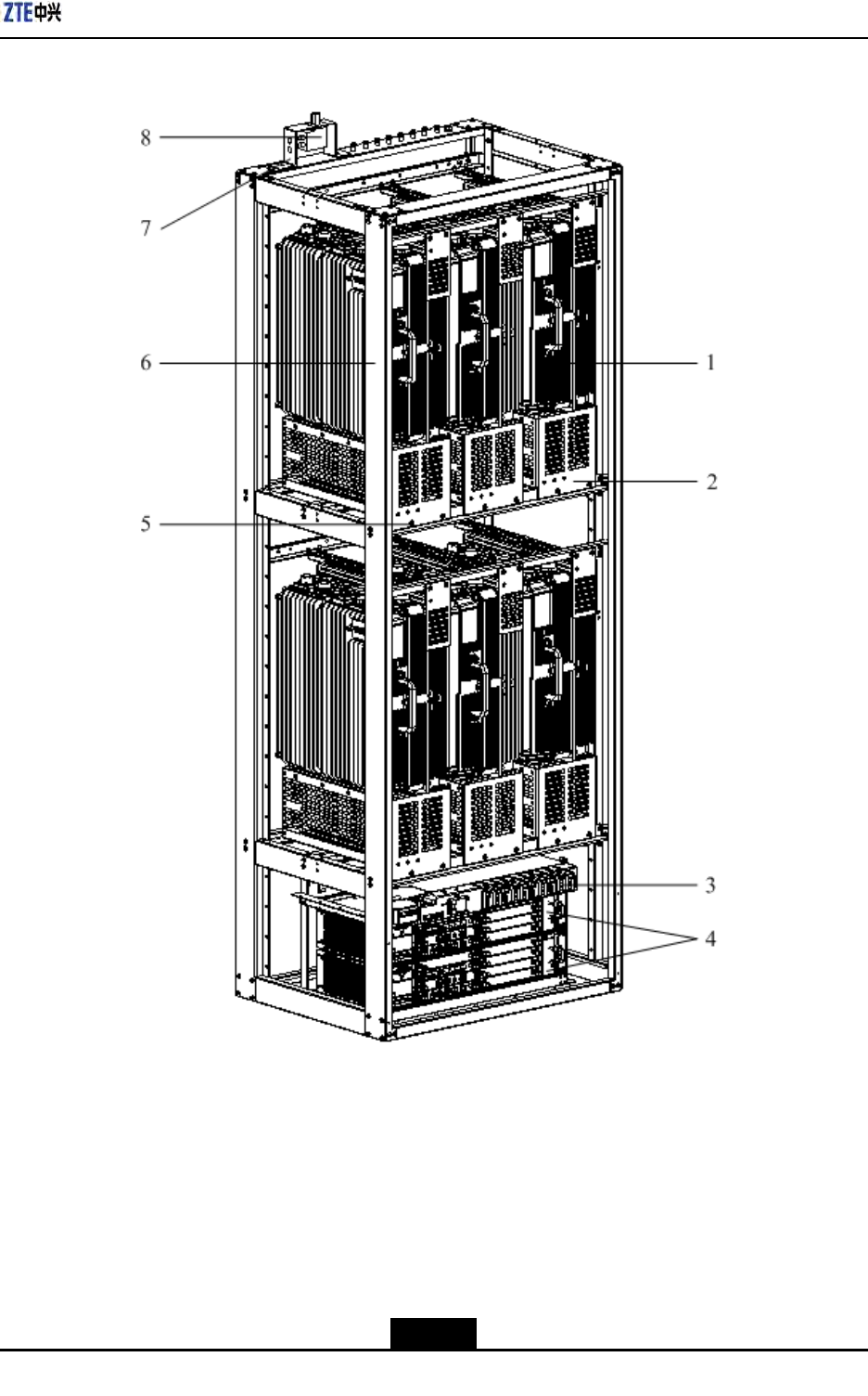
AppendixGPDM
FigureG-4PDMInstallationtoaSimpliedCabinet
1.ZXSDRR8860
2.ZXSDRR8860fixation
shelf
3.PDM
4.ZXSDRB8200C100
5.PanscrewM6×16
6.Simplifiedcabinet
7.GPSarresterrack
8.GPSarrester
4.InstallthepowercablesofBBUandRRU.Thepowercablecarriesfastenersbyitself,
installedatabayonetofPDMback,asshowninFigureG-5.
G-3
SJ-20100722143906-002|02/20/2011(R1.3)ZTEProprietaryandCondential
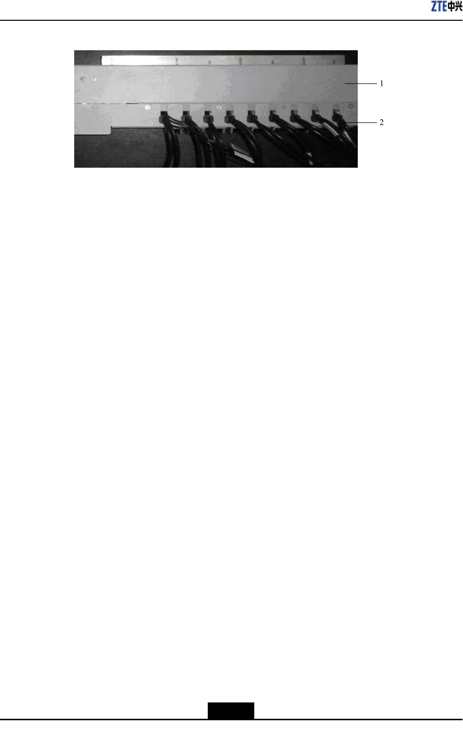
ZXSDRR8860InstallationManual
FigureG-5BBUandRRUPowerCableInstallation
1.PDM2.Powercable
5.Connecttheotherendofinternalcablesto-48Vconnectingterminal.Connectthe
-48VendofBBUandRRUpowercablestotheONendofswitches.Connectthe
-48VGNDendtothe-48VGNDconnectingterminal.Thenscrewdownboltswitha
screwdriver.
6.ConnecttheinputpowercablecarriedbyPDMselftotheconnectingterminal.
–EndofSteps–
G-4
SJ-20100722143906-002|02/20/2011(R1.3)ZTEProprietaryandCondential

Figures
Figure2-1InstallationFlow.......................................................................................2-2
Figure2-2PuttingtheMentalLatchinStraightDirection.........................................2-11
Figure2-3RemovingCoverBoard..........................................................................2-11
Figure2-4RemovingOtherBoards.........................................................................2-12
Figure2-5TakingOutComponentwithanAntistaticWristStrap.............................2-13
Figure3-1PoleAnchorClampComponents.............................................................3-4
Figure3-2PoleFixingBracketComponents.............................................................3-4
Figure3-3Pole-MountInstallation(1)......................................................................3-5
Figure3-4Pole-MountInstallation(2).......................................................................3-6
Figure3-5Pole-mountInstallation(1).......................................................................3-7
Figure3-6Pole-mountInstallation(2).......................................................................3-8
Figure3-7Pole-mountInstallation(3).......................................................................3-8
Figure3-8Pole-mountInstallation(1).......................................................................3-9
Figure3-9Pole-mountInstallation(2).....................................................................3-10
Figure3-10Pole-mountInstallation(3)...................................................................3-10
Figure3-11SupportingPanel..................................................................................3-11
Figure3-12HoleMarkingDesignTemplate(Unit:mm)...........................................3-12
Figure3-13SpaceRequirementforWall-mountInstallation(Unit:mm).................3-13
Figure3-14SupportingPanelInstallationonWall...................................................3-13
Figure3-15MountingCabinet................................................................................3-14
Figure4-1ExternalCableInstallationFlow...............................................................4-3
Figure4-2AppearanceofthePlasterandTape........................................................4-4
Figure4-3WrappingaLayerofT ape........................................................................4-4
Figure4-4WrappingThreeLayerofPlaster..............................................................4-5
Figure4-5WrappingaLayerofT ape........................................................................4-5
Figure4-6BindingCableFasteners..........................................................................4-6
Figure4-7PowerCablestructure.............................................................................4-6
Figure4-8GroundingCableStructure......................................................................4-8
Figure4-9ZXSDRR8860GroundingBolt................................................................4-8
Figure4-10Earth-networkCopperBar(Unit:mm)....................................................4-9
Figure4-11FiberConnectionbetweenZXSDRR8860andBBU.............................4-9
Figure4-12OpticalFiberInstallation.......................................................................4-10
I

ZXSDRR8860InstallationManual
Figure4-13FiberConnectionbetweenZXSDRR8860s........................................4-11
Figure4-14OpticalFiberInstallation.......................................................................4-11
Figure4-15EnvironmentMonitoringCable.............................................................4-12
Figure4-16AviationJackAppearance....................................................................4-12
Figure4-17AISGControlCableStructure..............................................................4-13
Figure4-18FrequencyPointExtensionCable........................................................4-14
Figure4-19RFJumperInstallation.........................................................................4-15
Figure4-20PIMDCAppearance.............................................................................4-17
Figure4-21InstallingPIMDC..................................................................................4-18
Figure4-22PIMDCConnection..............................................................................4-19
Figure4-23ConnectPowerInputCable.................................................................4-20
Figure4-24ConnectingOutputPowerCableandDryContactCables....................4-20
Figure5-1ZXSDRR8860ConguredwithCommonAntenna..................................5-2
Figure5-2ZXSDRR8860ConguredwithCommonAntenna,AISGDualT ower
Amplier.................................................................................................5-3
Figure5-3ZXSDRR8860ConguredwithElectricallyTunedAntenna(1)................5-4
Figure5-4ZXSDRR8860ConguredwithElectricallyTunedAntenna(2)................5-5
Figure5-5ZXSDRR8860ConguredwithElectricallyTunedAntennaandAISG
DualTowerAmplier...............................................................................5-6
Figure5-6MainAntennaFeederSystemInstallationFlow........................................5-9
Figure5-7AntennaInstallationPosition..................................................................5-10
Figure5-8DirectionalAntennaInstallation..............................................................5-12
Figure5-9AntennaDowntiltAdjustment.................................................................5-13
Figure5-10OmniDirectionalAntennaInstallation...................................................5-14
Figure5-11FeederFixing.......................................................................................5-17
Figure5-12HoistingFeederToTower....................................................................5-19
Figure5-13TripleFeederClipAppearance.............................................................5-20
Figure5-14FeederGroundingSchematicDiagram................................................5-21
Figure5-15GroundingSystem...............................................................................5-23
Figure5-16GroundingBarStructure......................................................................5-24
Figure5-17GroundingClip.....................................................................................5-24
Figure5-18InstallationHolePositions(Unit:mm)..................................................5-26
Figure5-19HermeticWindowInstallation...............................................................5-27
Figure5-20FeederintoRoomMode(1)................................................................5-28
Figure5-21FeederintoRoomMode(2).................................................................5-29
Figure5-22Antenna,FeederandJumperInstallation.............................................5-31
II

Figures
Figure5-23WaterproofInsulatingTape..................................................................5-32
Figure5-24PVCAdhesiveTape.............................................................................5-33
Figure5-25WrappingaLayerofPVCInsulatingT ape............................................5-33
Figure5-26WrappingThreeLayersofWaterInsulatingT ape(theFirst
Layer)...................................................................................................5-34
Figure5-27WrappingThreeLayersofWaterInsulatingTape(theSecond
Layer)...................................................................................................5-34
Figure5-28WrappingThreeLayersofWaterInsulatingTape(theThird
Layer)...................................................................................................5-34
Figure5-29WrappingThreeLayersofPVCInsulatingTape(theFirstLayer)...........5-35
Figure5-30WrappingThreeLayersofPVCInsulatingT ape(theSecond
Layer)...................................................................................................5-35
Figure5-31Fastening.............................................................................................5-36
Figure5-32FeederHermetic-windowDimension(Unit:mm)..................................5-36
Figure5-3312FeederHermetic-windowStructure.................................................5-37
Figure5-34InstallationHolePositions(Unit:mm).................................................5-38
Figure5-35FeederHermetic-windowInstallation...................................................5-39
Figure5-36ChassisJumpers.................................................................................5-40
FigureA-1ZXSDRR8860Cabinet-combinedInstallationConnection.......................A-1
FigureB-1CascadedCabinetConnection................................................................B-1
FigureB-2ZXSDRR8860OpticalFiberforCascadedCabinet.................................B-2
FigureC-1OAUAppearance...................................................................................C-1
FigureC-2OAUInterfaces.......................................................................................C-2
FigureC-3AnchorClampAssemblies.....................................................................C-2
FigureC-4FixingBracketAssemblies.....................................................................C-3
FigureC-5TwoSetsofAnchorClampAssemblies..................................................C-4
FigureC-6TwoSetsofFixingBracketAssemblies..................................................C-5
FigureC-7OAUBracket..........................................................................................C-6
FigureC-8TwoSetsofSupportingPanels...............................................................C-6
FigureC-9ThreeSetsofSupportingPanels............................................................C-7
FigureC-10OAUInstallation(1)..............................................................................C-8
FigureC-11OAUInstallation(2)..............................................................................C-9
FigureC-12OAURack..........................................................................................C-10
FigureC-13OAUInstallation(1).............................................................................C-11
FigureC-14OAUInstallation(2)............................................................................C-12
FigureC-15WaterproofEndCap...........................................................................C-13
III

ZXSDRR8860InstallationManual
FigureC-16LooseoffWaterproofEndCap...........................................................C-13
FigureC-17WaterproofEndCapStructure............................................................C-14
FigureC-18WaterproofEndCapInstallation.........................................................C-14
FigureC-19ACPowerCableConnection..............................................................C-15
FigureC-20OneACLightningBox,ThreeOAUsandThreeR8860Cable
Connection..........................................................................................C-16
FigureD-1OutdoorDCLightningBoxAppearance..................................................D-2
FigureD-2OutdoorDCLightningBoxInterface.......................................................D-3
FigureD-3InstallationParts.....................................................................................D-4
FigureD-4OutdoorDCLightningPoleInstallation..................................................D-5
FigureD-5OutdoorDCLightningBoxInterfaces.....................................................D-6
FigureD-6OutdoorDCLightningConnection..........................................................D-6
FigureE-1IndoorDCLightningBoxAppearance......................................................E-2
FigureE-2IndoorDCLightningBoxInterfaces.........................................................E-3
FigureE-3IndoorDCLightningBoxCableConnection(notconnectwithremote
alarm).....................................................................................................E-4
FigureF-1ACLightningBoxAppearance.................................................................F-2
FigureF-2ACLightningBoxInterface......................................................................F-3
FigureF-3ACLightningBoxInstallationParts..........................................................F-3
FigureF-4ACLightningPoleInstallation..................................................................F-4
FigureF-5OneACLightningBoxandOne(ortwo)R8841CableConnection...........F-5
FigureF-6TwoACLightningBoxandThreeR8841CableConnection....................F-6
FigureF-7OneACLightningBox,ThreeOAUsandThreeR8860Cable
Connection.............................................................................................F-6
FigureF-8ShieldedGroundingKitStructure.............................................................F-7
FigureF-9GroundingBody1(adoptablefor6mm2two-coreoutdoorpower
cable).....................................................................................................F-8
FigureF-10GroundingBody2(adoptablefor16mm2two-coreoutdoorpower
cable).....................................................................................................F-8
FigureF-11ConnectingTerminal(dual-hole).............................................................F-8
FigureF-12ConnectingTerminal(single-hole)..........................................................F-9
FigureG-1PowerDistributionBoxPlane.................................................................G-1
FigureG-2PowerDistributionBox...........................................................................G-1
FigureG-3InsideCabletoconnectwithPDM..........................................................G-2
FigureG-4PDMInstallationtoaSimpliedCabinet.................................................G-3
FigureG-5BBUandRRUPowerCableInstallation.................................................G-4
IV

Tables
Table1-1SafetySymbolsDescription.......................................................................1-2
Table2-1ToolandMeterList....................................................................................2-4
Table3-1ZXSDRR8860EngineeringIndices...........................................................3-1
Table3-2JD40K085C20H2–K1ZDCLightningBoxTechnicalIndices......................3-2
Table3-3GPAD501M54-1AExternalAC-to-DCConversionLightningBox
TechnicalIndices......................................................................................3-2
Table3-4MainComponentList1.............................................................................3-3
Table3-5MainComponentList2.............................................................................3-3
Table3-6MainComponentList3..............................................................................3-4
Table3-7MainComponents...................................................................................3-11
Table4-1ZXSDRR8860ExternalCableConnectionRelationship............................4-1
Table4-2ColorandSpecicationofDCPowerCable..............................................4-7
Table4-3ColorandSpecicationofACPowerCable..............................................4-7
Table4-4CablePinDescription.............................................................................4-12
Table4-5AISGControlCableDescription..............................................................4-13
Table4-6EngineeringTechnicalIndicesofPIMDC.................................................4-16
Table6-1ConnectionRelationship............................................................................6-2
Table6-2ConnectionRelationship............................................................................6-3
TableD-1EngineeringTechnicalIndices..................................................................D-1
TableE-1EngineeringTechnicalIndices...................................................................E-1
TableF-1EngineeringTechnicalIndices...................................................................F-1
V

Tables
Thispageintentionallyleftblank.

Glossary
AISG
-AntennaInterfaceStandardsGroup
BBU
-BaseBandUnit
BSC
-BaseStationController
BTS
-BaseTransceiverStation
RF
-RadioFrequency
VSWR
-VoltageStandingWaveRatio
VII