ZTE R8882S1700 UMTS and LTE Remote Radio Unit User Manual 3
ZTE Corporation UMTS and LTE Remote Radio Unit 3
ZTE >
Contents
- 1. User manual
- 2. User manual 1
- 3. User manual 2
- 4. User manual 3
- 5. User manual 4
User manual 3

ZXSDRR8882
MacroRadioRemoteUnit
HardwareDescription
HardwareVersion:HV2.1
ZTECORPORATION
No.55,Hi-techRoadSouth,ShenZhen,P .R.China
Postcode:518057
Tel:+86-755-26771900
Fax:+86-755-26770801
URL:http://support.zte.com.cn
E-mail:support@zte.com.cn
LEGALINFORMATION
Copyright©2014ZTECORPORATION.
Thecontentsofthisdocumentareprotectedbycopyrightlawsandinternationaltreaties.Anyreproductionor
distributionofthisdocumentoranyportionofthisdocument,inanyformbyanymeans,withoutthepriorwritten
consentofZTECORPORATIONisprohibited.Additionally,thecontentsofthisdocumentareprotectedby
contractualcondentialityobligations.
Allcompany,brandandproductnamesaretradeorservicemarks,orregisteredtradeorservicemarks,ofZTE
CORPORATIONoroftheirrespectiveowners.
Thisdocumentisprovided“asis”,andallexpress,implied,orstatutorywarranties,representationsorconditions
aredisclaimed,includingwithoutlimitationanyimpliedwarrantyofmerchantability,tnessforaparticularpurpose,
titleornon-infringement.ZTECORPORATIONanditslicensorsshallnotbeliablefordamagesresultingfromthe
useoforrelianceontheinformationcontainedherein.
ZTECORPORATIONoritslicensorsmayhavecurrentorpendingintellectualpropertyrightsorapplications
coveringthesubjectmatterofthisdocument.ExceptasexpresslyprovidedinanywrittenlicensebetweenZTE
CORPORATIONanditslicensee,theuserofthisdocumentshallnotacquireanylicensetothesubjectmatter
herein.
ZTECORPORATIONreservestherighttoupgradeormaketechnicalchangetothisproductwithoutfurthernotice.
UsersmayvisittheZTEtechnicalsupportwebsitehttp://support.zte.com.cntoinquireforrelatedinformation.
TheultimaterighttointerpretthisproductresidesinZTECORPORATION.
RevisionHistory
SerialNo.PublishingDatePublishingReason
R1.02015-01-04Firstedition
SerialNumber:SJ-20150104112914-002
PublishingDate:2015-01-04(R1.0)
SJ-20150104112914-002|2015-01-04(R1.0)ZTEProprietaryandCondential
AboutThisManual
Purpose
ThismanualdescribestheZXSDRR8882,includingthechassisandexternalcables.
IntendedAudience
Thismanualisintendedforthefollowingpersonnel:
lEquipmentinstallationengineers
lMaintenanceengineers
WhatIsinThisManual
Thismanualcontainsthefollowingchapters.
Chapter1,ExternalViewDescribestheexternalviewanddimensionsoftheZXSDRR8882.
Chapter2,External
Interfaces
DescribestheexternalinterfacesoftheZXSDRR8882.
Chapter3,IndicatorsDescribestheindicatorsoftheZXSDRR8882.
Chapter4,External
Cables
DescribestheexternalcablesoftheZXSDRR8882.
Conventions
Thismanualusesthefollowingconventions.
TypefaceMeaning
Danger:indicatesanimminentlyhazardoussituation.Failureto
complycanresultindeathorseriousinjury,equipmentdamage,orsite
breakdown.
Warning:indicatesapotentiallyhazardoussituation.Failuretocomply
canresultinseriousinjury,equipmentdamage,orinterruptionofmajor
services.
Caution:indicatesapotentiallyhazardoussituation.Failuretocomply
canresultinmoderateinjury,equipmentdamage,orinterruptionof
minorservices.
Note:providesadditionalinformationaboutacertaintopic.
I
SJ-20150104112914-002|2015-01-04(R1.0)ZTEProprietaryandCondential

Thispageintentionallyleftblank.
II
SJ-20150104112914-002|2015-01-04(R1.0)ZTEProprietaryandCondential

Contents
AboutThisManual.........................................................................................I
Chapter1ExternalView.............................................................................1-1
Chapter2ExternalInterfaces....................................................................2-1
Chapter3Indicators...................................................................................3-1
Chapter4ExternalCables.........................................................................4-1
4.1ProtectiveGroundingCable................................................................................4-1
4.2DCPowerInputCable........................................................................................4-2
4.3AntennaFeederCable........................................................................................4-3
4.4FiberCable........................................................................................................4-3
4.5ExternalMonitoringCable...................................................................................4-5
4.6AISGControlCable............................................................................................4-6
Figures.............................................................................................................I
Tables............................................................................................................III
Glossary.........................................................................................................V
I
SJ-20150104112914-002|2015-01-04(R1.0)ZTEProprietaryandCondential

Thispageintentionallyleftblank.
II
SJ-20150104112914-002|2015-01-04(R1.0)ZTEProprietaryandCondential
Chapter1
ExternalView
TheZXSDRR8882hastwomodels:
lZXSDRR8882withtwoopticalinterfaces
lZXSDRR8882withthreeopticalinterfaces
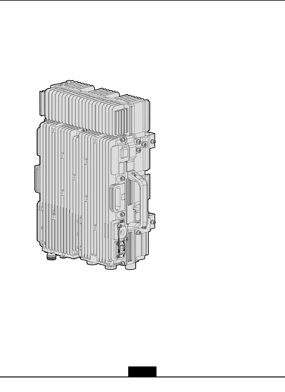
Figure1-1showstheexternalviewofaZXSDRR8882withtwoopticalinterfaces.
Figure1-1ZXSDRR8882WithTwoOpticalInterfaces
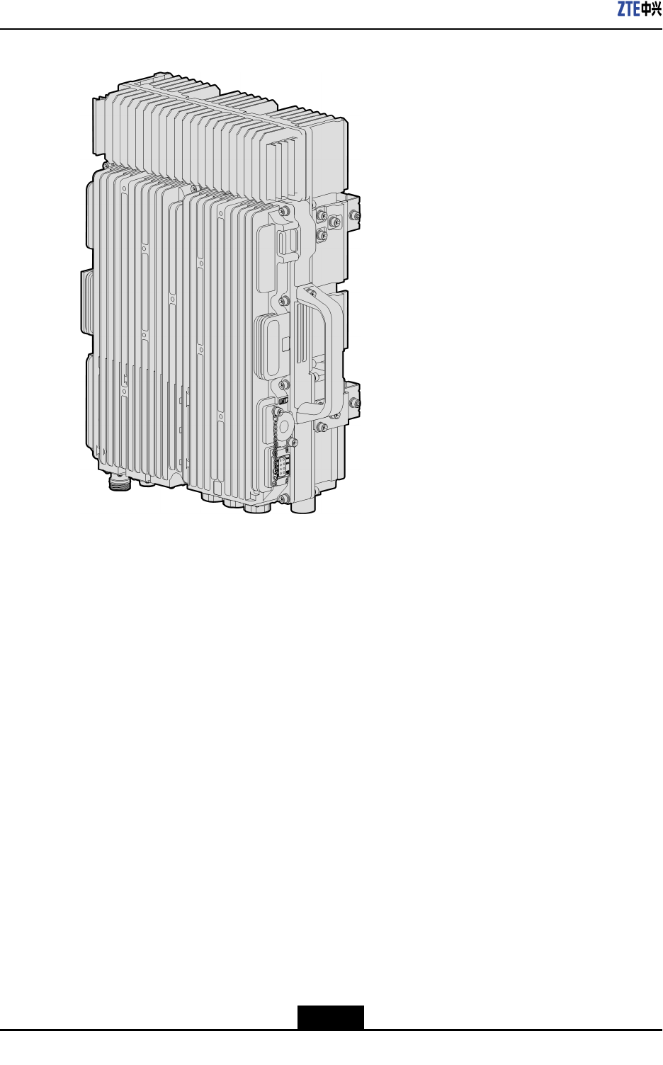
Figure1-2showstheexternalviewofaZXSDRR8882withthreeopticalinterfaces.
1-1
SJ-20150104112914-002|2015-01-04(R1.0)ZTEProprietaryandCondential
ZXSDRR8882HardwareDescription
Figure1-2ZXSDRR8882WithThreeOpticalInterfaces
Dimensions:480mm×320mm×150mm(H×W×D)
Weight:23kg
1-2
SJ-20150104112914-002|2015-01-04(R1.0)ZTEProprietaryandCondential
Chapter2
ExternalInterfaces
TheZXSDRR8882hastwomodels:
lZXSDRR8882withtwoopticalinterfaces
lZXSDRR8882withthreeopticalinterfaces
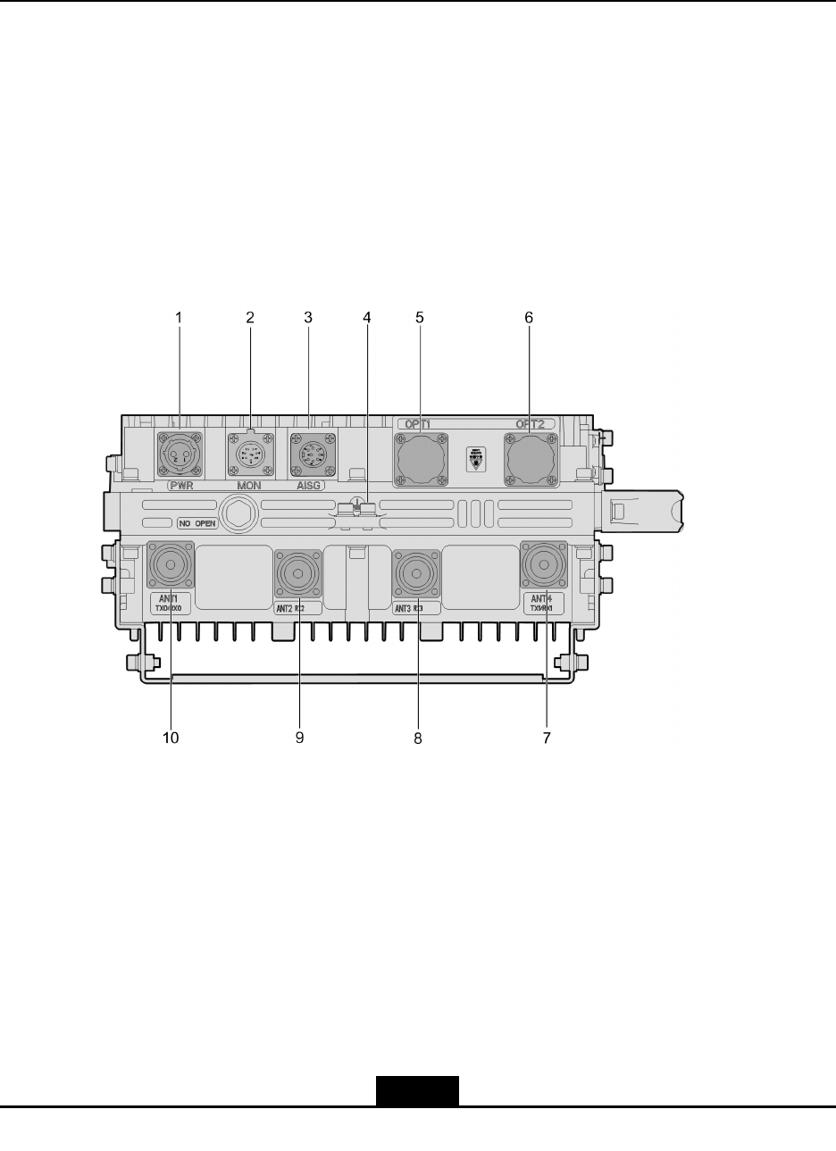
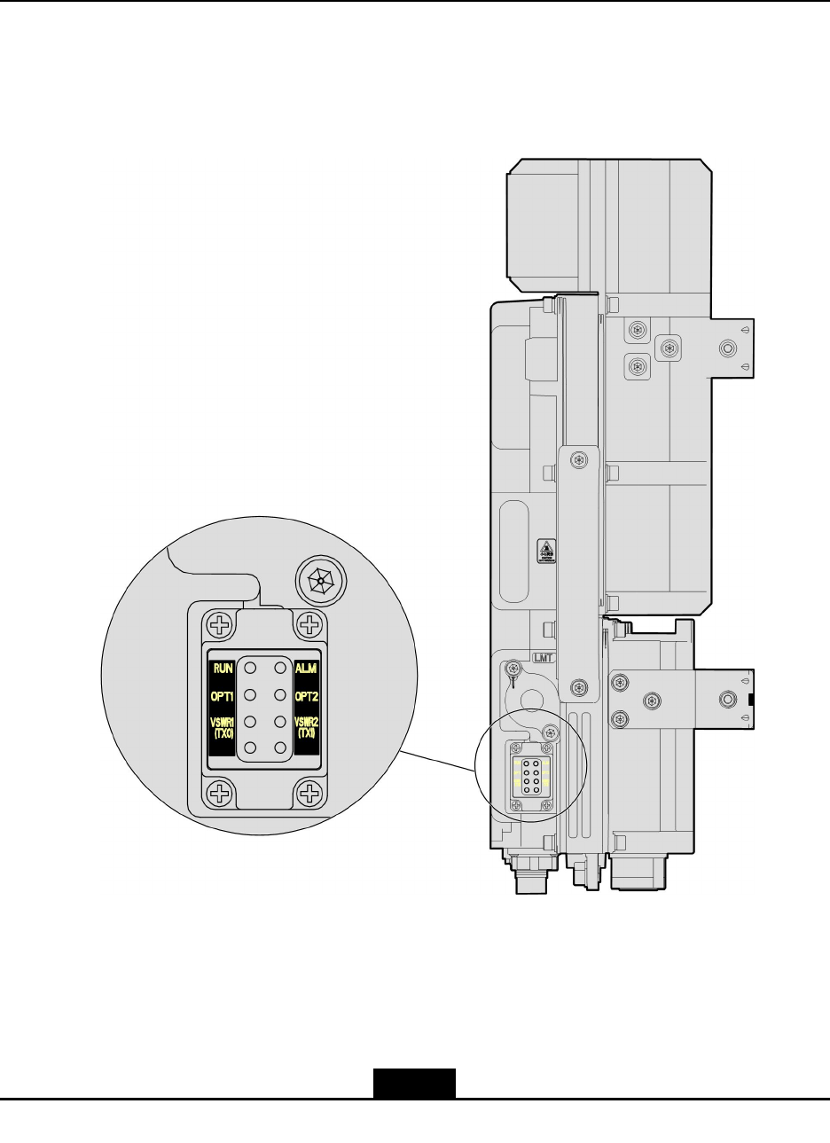
ExternalInterfaces(ZXSDRR8882WithTwoOpticalInterfaces)
ExternalinterfacesarelocatedatthebottomandtherightsideoftheZXSDRR8882,see
Figure2-1andFigure2-2.
Figure2-1ExternalInterfacesattheBottom(ZXSDRR8882WithTwoOpticalInterfaces)
2-1
SJ-20150104112914-002|2015-01-04(R1.0)ZTEProprietaryandCondential
ZXSDRR8882HardwareDescription
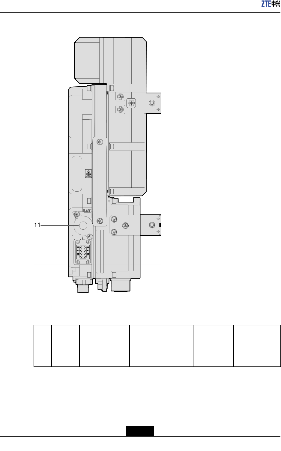
Figure2-2ExternalInterfaceattheRightSide(ZXSDRR8882WithTwoOptical
Interfaces)
Foradescriptionoftheexternalinterfaces,refertoTable2-1.
Table2-1ExternalInterfaces(ZXSDRR8882WithTwoOpticalInterfaces)
No.Silkscr-
een
InterfaceConnectorTypeCompliant
Protocol
Function
1PWR-48VDCpower
inputinterface
2-pinroundplastic
connector(male)
-Provides-48V
DCpowersupply.
2-2
SJ-20150104112914-002|2015-01-04(R1.0)ZTEProprietaryandCondential
Chapter2ExternalInterfaces
No.Silkscr-
een
InterfaceConnectorTypeCompliant
Protocol
Function
2MONExternal
monitoring
interface
8-pinstraight
panel-mountedwelded
roundsocket(male)
-Supportssignal
interaction
betweenthe
RRUand
externaldevices,
including
alarmsignals,
RS485/RS422
controlsignals,
andtwopairsof
drycontactinput
signals.
3AISGAISGinterface8-pinsocketwitha
squarebase
AISGSupportsthe
AISGsignal
connectionto
anRETantenna.
4-PEinterface16mm2yellow/green
roundterminal
-Provides
protectiveearth.
5OPT1Interfacefor
connectingaBBU
andanRRU,or
cascadingRRUs
LCopticalconnector
(IEC874)
ZTEprivate
protocol
6OPT2Interfacefor
connectingaBBU
andanRRU,or
cascadingRRUs
LCopticalconnector
(IEC874)
ZTEprivate
protocol
Supportssignal
transmission
betweenanRRU
andaBBU,or
betweenRRUs.
7ANT4
TX1/
RX1
Antennafeeder
interface
(Tx1/Rx1)
DINconnector-
8ANT3
RX3
(Op-
tional)
Antennafeeder
interface(Rx3)
DINconnector-
9ANT2
RX2
(Op-
tional)
Antennafeeder
interface(Rx2)
DINconnector-
A1/2"foam
dielectriccable
(50Ω)isused
forRFsignal
transmission.
2-3
SJ-20150104112914-002|2015-01-04(R1.0)ZTEProprietaryandCondential
ZXSDRR8882HardwareDescription
No.Silkscr-
een
InterfaceConnectorTypeCompliant
Protocol
Function
10ANT1
TX0/
RX0
Antennafeeder
interface
(Tx0/Rx0)
DINconnector-
11LMTEthernetinterface
foroperationand
maintenance
8P8Cshieldedangle
PCBsocketwithLED
(leftyellow,rightgreen)
-Supports
operationand
maintenanceon
theRRU,and
outputsinternal
signals.
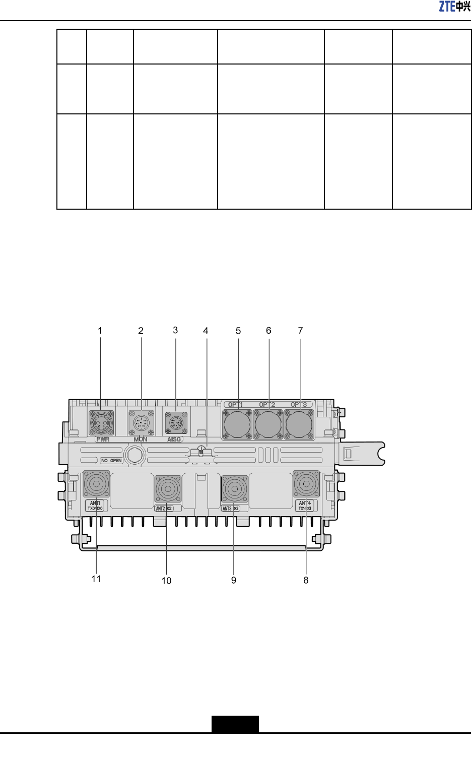
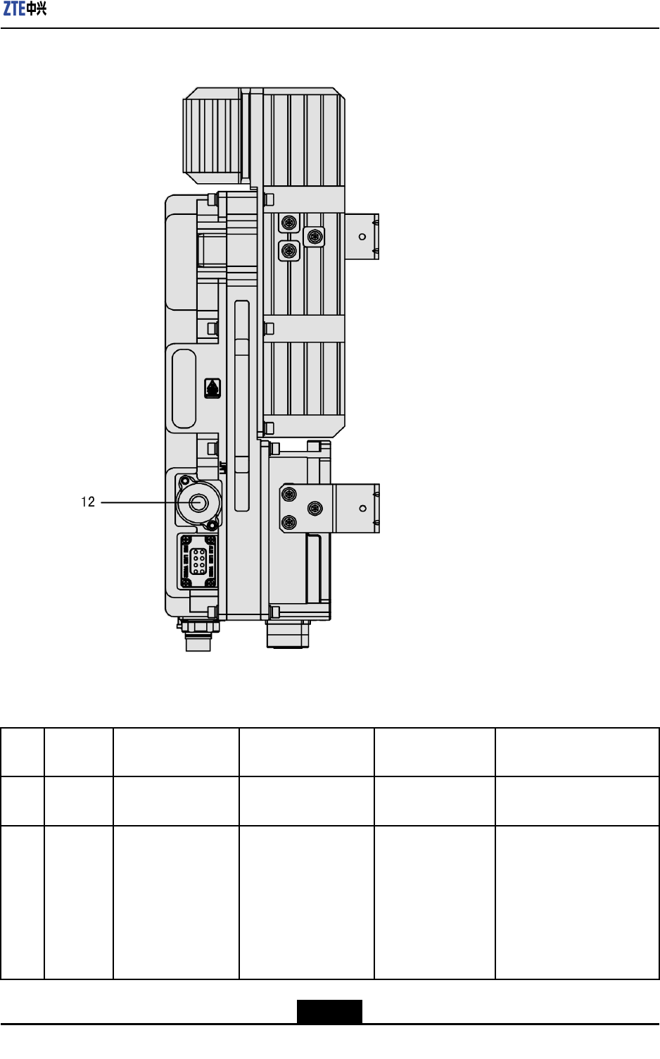
ExternalInterfaces(ZXSDRR8882WithThreeOpticalInterfaces)
TheexternalinterfacesarelocatedatthebottomandtherightsideoftheZXSDRR8882,
seeFigure2-3andFigure2-4.
Figure2-3ExternalInterfacesattheBottom(ZXSDRR8882WithThreeOptical
Interfaces)
2-4
SJ-20150104112914-002|2015-01-04(R1.0)ZTEProprietaryandCondential
Chapter2ExternalInterfaces
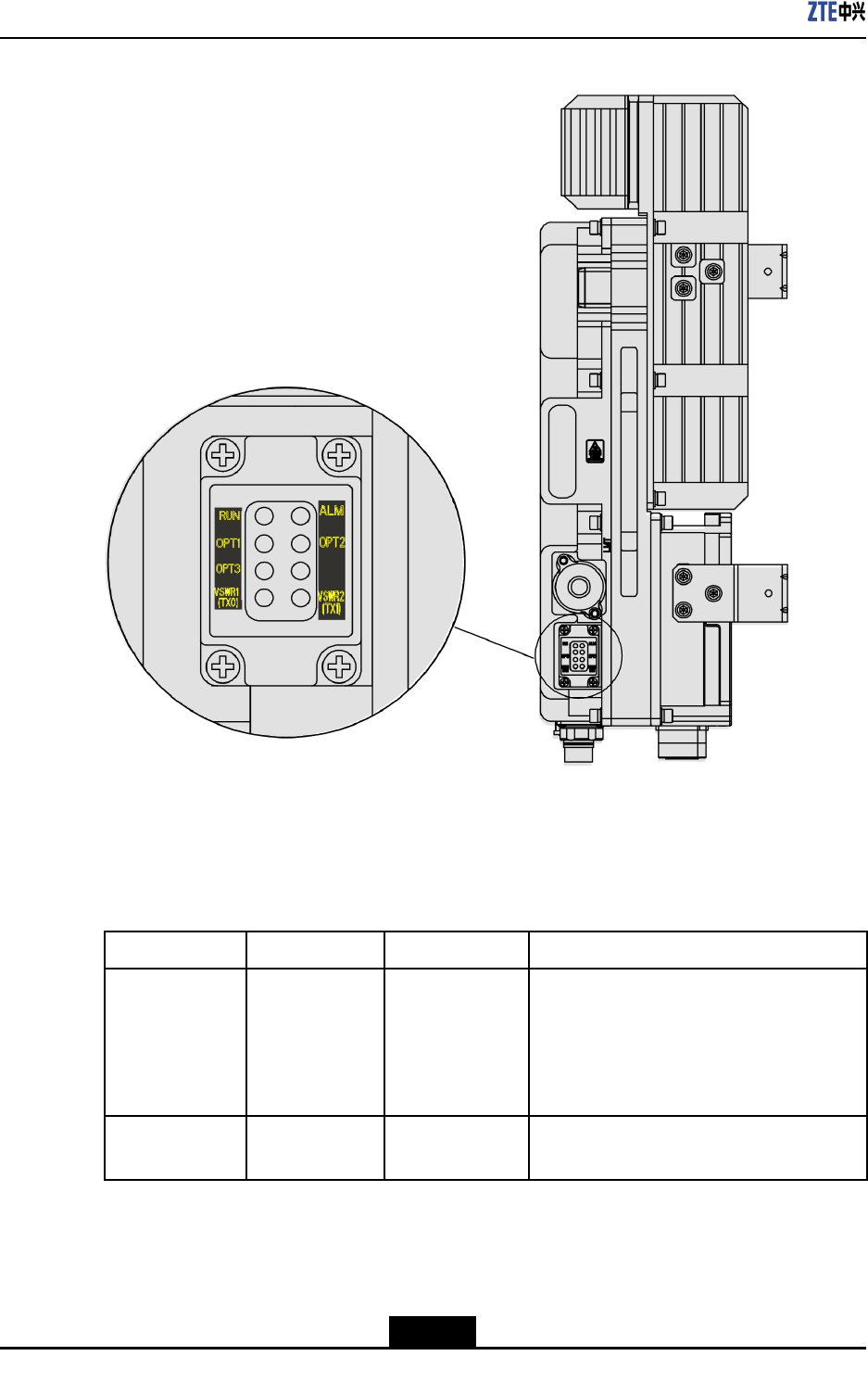
Figure2-4ExternalInterfaceattheRightSide(ZXSDRR8882WithThreeOptical
Interfaces)
Foradescriptionoftheexternalinterfaces,refertoTable2-2.
Table2-2ExternalInterfaces(ZXSDRR8882WithThreeOpticalInterfaces)
No.Silkscr-
een
InterfaceConnectorTypeCompliant
Protocol
Function
1PWR-48VDCpower
inputinterface
2-pinroundplastic
connector(male)
-Provides-48VDCpower
supply.
2MONExternalmonitoring
interface
8-pinstraight
panel-mounted
weldedroundsocket
(male)
-Supportssignalinteraction
betweentheRRU
andexternaldevices,
includingalarmsignals,
RS485/RS422control
signals,andtwopairsof
drycontactinputsignals.
2-5
SJ-20150104112914-002|2015-01-04(R1.0)ZTEProprietaryandCondential

ZXSDRR8882HardwareDescription
No.Silkscr-
een
InterfaceConnectorTypeCompliant
Protocol
Function
3AISGAISGinterface8-pinsocketwitha
squarebase
AISGSupportstheAISGsignal
connectiontoanRET
antenna.
4-PEinterface16mm2yellow/green
roundterminal
-Providesprotectiveearth.
5OPT1Interfacefor
connectingaBBU
andanRRU,or
cascadingRRUs
LCopticalconnector
(IEC874)
ZTEprivate
protocol
6OPT2Interfacefor
connectingaBBU
andanRRU,or
cascadingRRUs
LCopticalconnector
(IEC874)
ZTEprivate
protocol
7OPT3Interfacefor
cascadingRRUs
onthesamebranch
LCopticalconnector
(IEC874)
ZTEprivate
protocol
Supportssignal
transmissionbetween
anRRUandaBBU,or
betweenRRUs.
8ANT4
TX1/RX1
Antennainterface
(Tx1/Rx1)
DINconnector-
9ANT3
RX3(Op-
tional)
Antennainterface
(Rx3)
DINconnector-
10ANT2
RX2(Op-
tional)
Antennainterface
(Rx2)
DINconnector-
11ANT1
TX0/RX0
Antennainterface
(Tx0/Rx0)
DINconnector-
A1/2"foamdielectriccable
(50Ω)isusedforRFsignal
transmission.
12LMTEthernetinterface
foroperationand
maintenance
8P8Cshieldedangle
PCBmountsocket
withLED(leftyellow,
rightgreen)
-Supportsoperationand
maintenanceonthe
RRU,andoutputsinternal
signals.
2-6
SJ-20150104112914-002|2015-01-04(R1.0)ZTEProprietaryandCondential
ZXSDRR8882HardwareDescription
Figure3-2IndicatorsoftheZXSDRR8882WithThreeOpticalInterfaces
Thestatusoftheindicatorsvarieswithdifferentsoftwareversions.
ForadescriptionoftheindicatorsontheZXSDRR8882panelofV4.09.21/V4.11.10,refer
toTable3-1.
Table3-1IndicatorDescription(V4.09.21/V4.11.10)
NameMeaningColorOperationMode
RUNPower-onstatus
indicatorGreen
Flashingat2Hz:Thesystemisoperating
properly.
Litandotherblinkingmodes:Thesystem
isbeingstartedorisnotoperatingproperly.
Notlit:Thesystemisnotpoweredon.
ALMAlarmindicatorRedLit:Thereisanalarmreported.
Notlit:Thereisnoalarmreported.
3-2
SJ-20150104112914-002|2015-01-04(R1.0)ZTEProprietaryandCondential
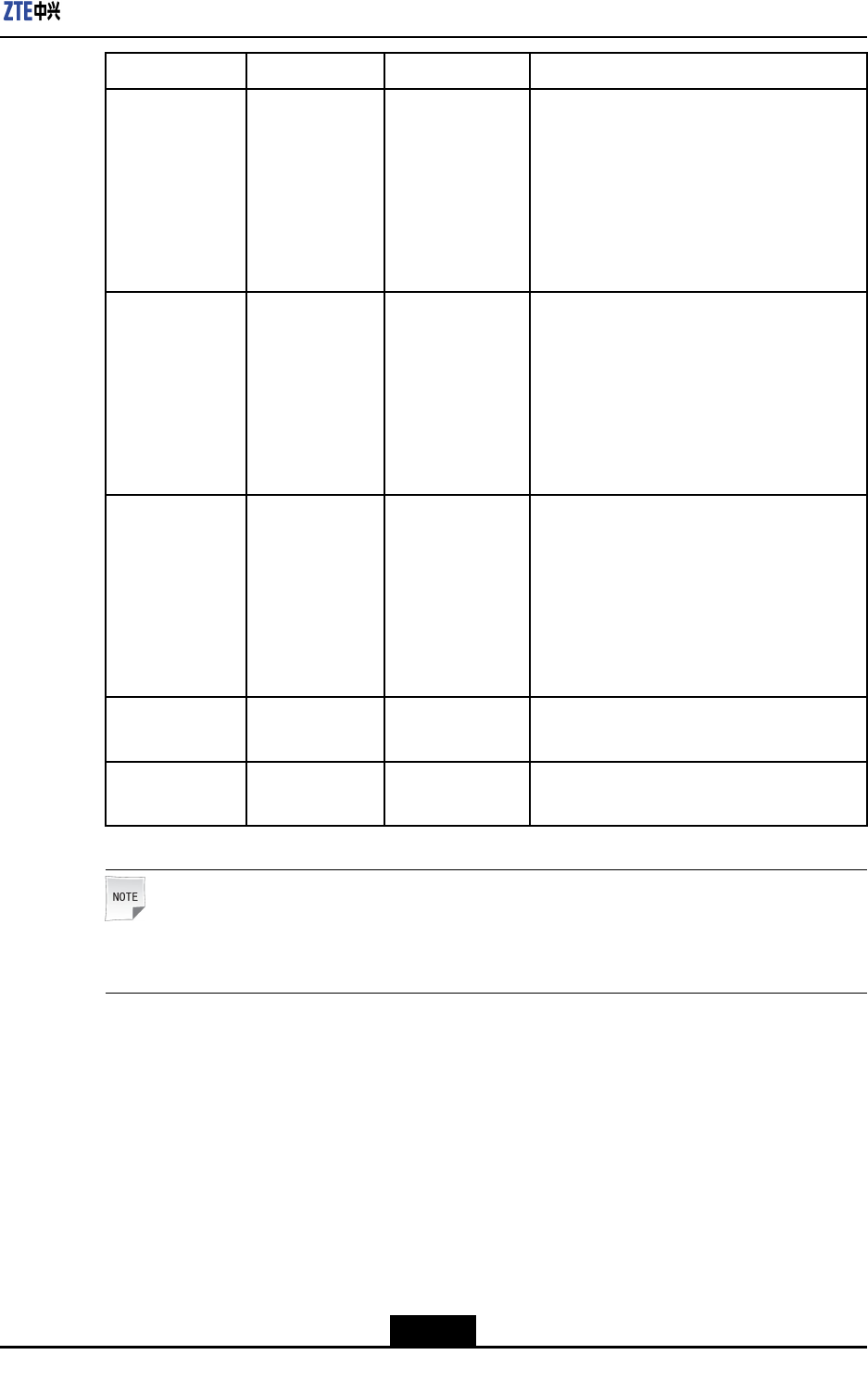
Chapter3Indicators
NameMeaningColorOperationMode
OPT1
Opticalinterface
1statusindica-
tor
Green
Flashing:Opticalinterface1is
communicatingproperly.
Lit:Opticalinterface1isnotcommunicating
properly(withopticalsignals).
Notlit:Opticalinterface1isnot
communicatingproperly(withoutoptical
signals).
OPT2
Opticalinterface
2statusindica-
tor
Green
Flashing:Opticalinterface2is
communicatingproperly.
Lit:Opticalinterface2isnotcommunicating
properly(withopticalsignals).
Notlit:Opticalinterface2isnot
communicatingproperly(withoutoptical
signals).
OPT3
Opticalinterface
3statusindica-
tor
Green
Flashing:Opticalinterface3is
communicatingproperly.
Lit:Opticalinterface3isnotcommunicating
properly(withopticalsignals).
Notlit:Opticalinterface3isnot
communicatingproperly(withoutoptical
signals).
VSWR1Tx0VSWRsta-
tusindicatorRedLit:TX0antennaVSWRalarm
Notlit:normalTX0antennaVSWR
VSWR2Tx1VSWRsta-
tusindicatorRedLit:TX1antennaVSWRalarm
Notlit:normalTX1antennaVSWR
Note:
TheZXSDRR8882withtwoopticalinterfacesdoesnothavetheOPT3indicator.
ForadescriptionoftheindicatorsontheZXSDRR8882panelofV4.12,refertoTable3-2.
3-3
SJ-20150104112914-002|2015-01-04(R1.0)ZTEProprietaryandCondential

ZXSDRR8882HardwareDescription
Table3-2IndicatorDescription(V4.12)
NameMeaningColorOperationMode
RUNPower-onstatus
indicatorGreen
Notlit:Thesystemisnotpoweredonoris
notoperatingproperly.
Lit:Thesystemisbeingpoweredonbutis
notoperatingproperly.
Flashingslowly(litforonesecondandnot
litforonesecond):Thesystemsoftware
isbeingstarted.
Flashingnormally(litfor0.3secondandnot
litfor0.3second):Thesystemisoperating
properlyandtheRRUiscommunicating
withtheBBUproperly.
Flashingrapidly(litfor70millisecondsand
notlitfor70milliseconds):Thesystemis
operatingproperly,butthecommunication
betweentheRRUandtheBBUisnotset
uporthecommunicationisdisconnected.
ALMAlarmindicatorRedLit:Thereisanalarmreported.
Notlit:Thereisnoalarmreported.
OPT1
Opticalinterface
1statusindica-
tor
Green
Flashing:Opticalinterface1is
communicatingproperly.
Lit:Opticalinterface1isnotcommunicating
properly(withopticalsignals).
Notlit:Opticalinterface1isnot
communicatingproperly(withoutoptical
signals).
OPT2
Opticalinterface
2statusindica-
tor
Green
Flashing:Opticalinterface2is
communicatingproperly.
Lit:Opticalinterface2isnotcommunicating
properly(withopticalsignals).
Notlit:Opticalinterface2isnot
communicatingproperly(withoutoptical
signals).
OPT3
Opticalinterface
3statusindica-
tor
Green
Flashing:Opticalinterface3is
communicatingproperly.
Lit:Opticalinterface3isnotcommunicating
properly(withopticalsignals).
Notlit:Opticalinterface3isnot
communicatingproperly(withoutoptical
signals).
3-4
SJ-20150104112914-002|2015-01-04(R1.0)ZTEProprietaryandCondential

Chapter3Indicators
NameMeaningColorOperationMode
VSWR1Tx0VSWRsta-
tusindicatorRedLit:TX0antennaVSWRalarm
Notlit:normalTX0antennaVSWR
VSWR2Tx1VSWRsta-
tusindicatorRedLit:TX1antennaVSWRalarm
Notlit:normalTX1antennaVSWR
Note:
TheZXSDRR8882withtwoopticalinterfacesdoesnothavetheOPT3indicator.
3-5
SJ-20150104112914-002|2015-01-04(R1.0)ZTEProprietaryandCondential

ZXSDRR8882HardwareDescription
Thispageintentionallyleftblank.
3-6
SJ-20150104112914-002|2015-01-04(R1.0)ZTEProprietaryandCondential
Chapter4
ExternalCables
ThischapterdescribestheexternalcablesoftheZXSDRR8882.
TableofContents
ProtectiveGroundingCable........................................................................................4-1
DCPowerInputCable................................................................................................4-2
AntennaFeederCable...............................................................................................4-3
FiberCable................................................................................................................4-3
ExternalMonitoringCable..........................................................................................4-5
AISGControlCable....................................................................................................4-6
4.1ProtectiveGroundingCable
Function
TheprotectivegroundingcableprovidesprotectiveearthfortheZXSDRR8882chassis.
ExternalView
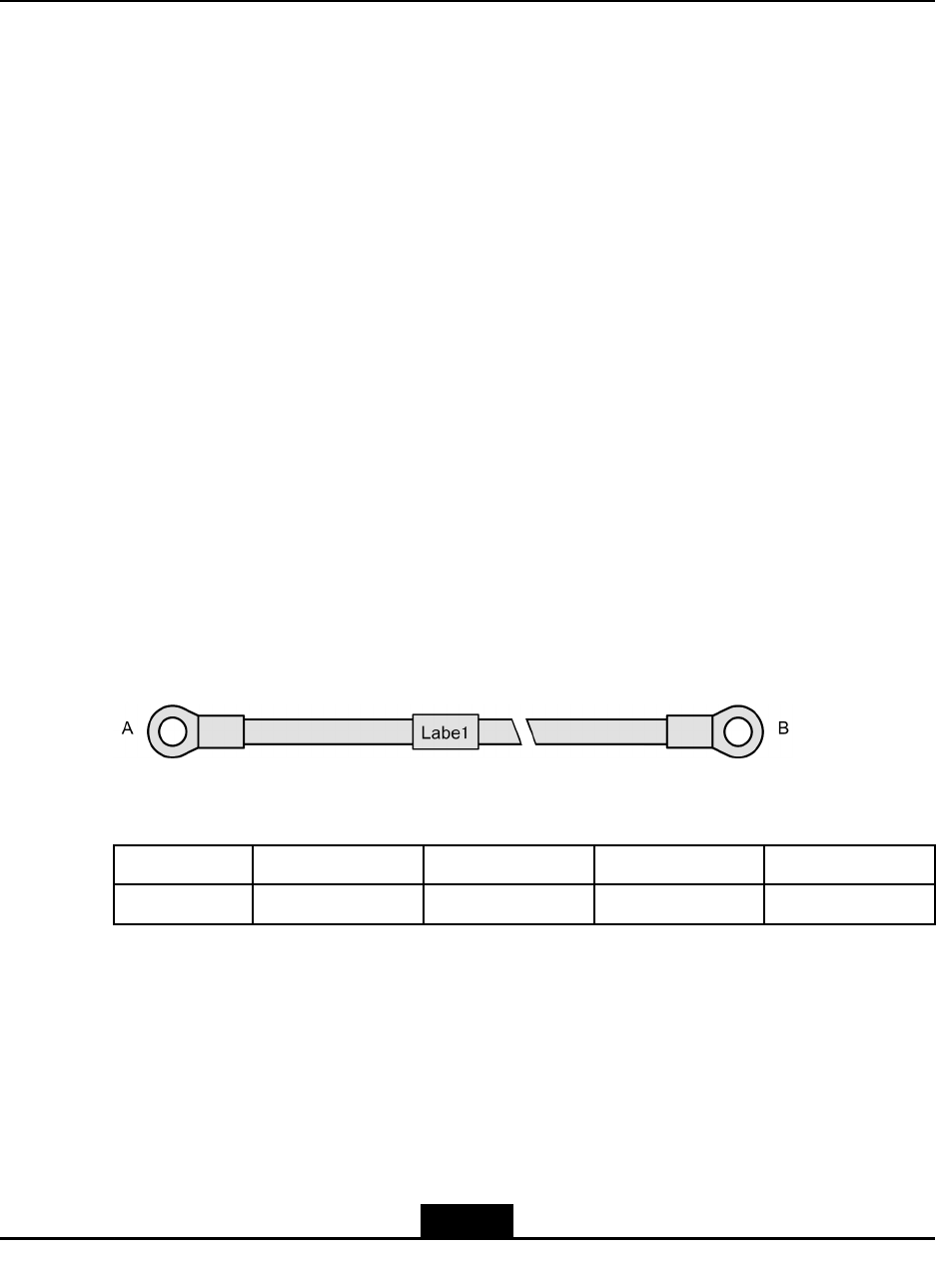
Thiscableisa16mm2green/yellowcable.ATNR22-8lugiscrimpedonbothends,see
Figure4-1.
Figure4-1ProtectiveGroundingCable
SignalDenition
NameDenitionPin(EndA)Pin(EndB)CoreColor
PEProtectiveearth--Green/yellow
Connections
lEndBisconnectedtothegroundingbarandtightenedwithabolt.
lEndAisconnectedtotheprotectivegroundingterminalontheZXSDRR8882chassis
andtightenedwithabolt.
4-1
SJ-20150104112914-002|2015-01-04(R1.0)ZTEProprietaryandCondential
ZXSDRR8882HardwareDescription
Note:
IfthereisaPIMDClightningprotectionbox,endAoftheprotectivegroundingcableis
connectedtotheprotectivegroundingportoftheZXSDRR8882.EndBisconnectedto
thelightningprotectionboxandthenconnectedtothegroundingbarthroughthebox.
4.2DCPowerInputCable
Function
TheDCpowerinputcableprovidestheinputofa-48VDCpowerfortheZXSDRR8882
chassis.
ExternalView
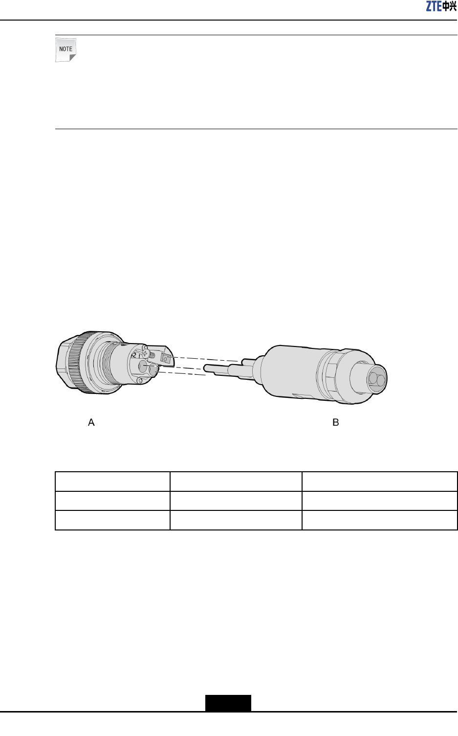
Figure4-2showstheexternalviewofaDCpowerinputcable.
Figure4-2DCPowerInputCable
SignalDenition
NameDenitionCoreColor
-48V-48VDCpowerBlue
-48VGND-48VDCgroundBlack
Connections
lEndAisconnectedtothePWRinterfaceoftheZXSDRR8882.
lEndBisconnectedtothecorrespondingterminalsonthepowersupplyadapter.
4-2
SJ-20150104112914-002|2015-01-04(R1.0)ZTEProprietaryandCondential
Chapter4ExternalCables
Note:
TheEPBCembeddedlightningprotectorisusedfortheequipment,andexternalsignals
arenottransmittedthroughthecabletransitbox.Duringinstallation,eldengineersneed
tomakeaDCpowerinputcableonsiteinaccordancewiththeavailablepoweraviation
headandconnectthepowercabletothepowerconnector.
4.3AntennaFeederCable
Function
TheantennafeedercableconnectstheantennafeederinterfaceontheZXSDRR8882
chassistothemainfeeder,supportingtransmittingandreceivingofradiosignals.
ExternalView
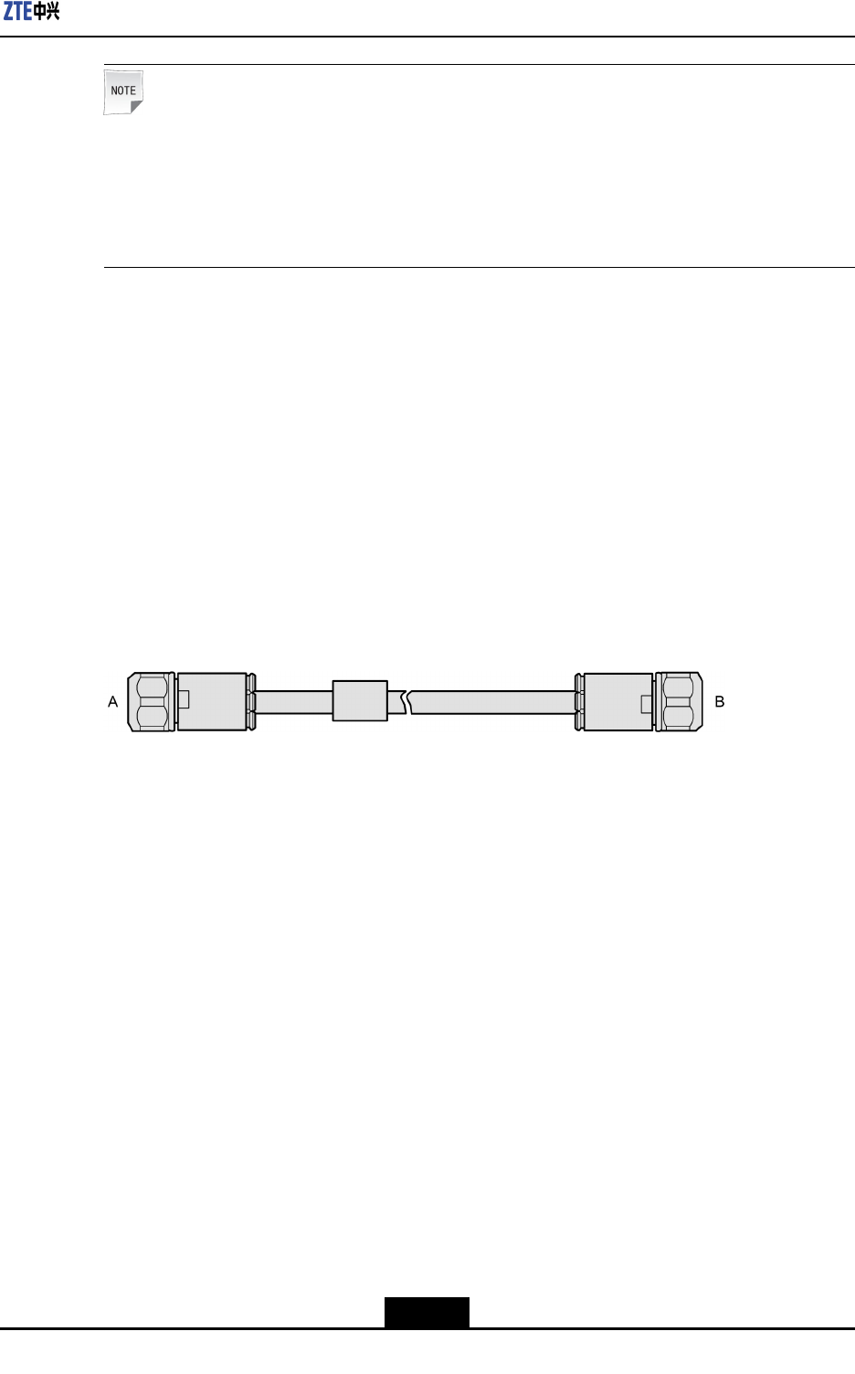
Thiscableisan1/2"RFcable(50Ω).ADINconnectorismountedonbothends,see
Figure4-3.
Figure4-3AntennaFeederCable
SignalDescription
None
Connections
lOneendofthecableisconnectedtotheANTinterfaceontheZXSDRR8882chassis.
lTheotherendofthecableisconnectedtothemainfeeder.
4.4FiberCable
Function
IntheZXSDRR8882system,abercablecanbeusedto:
lconnectanRRUtoaBBU.
lconnecttwocascadedRRUs.
4-3
SJ-20150104112914-002|2015-01-04(R1.0)ZTEProprietaryandCondential
ZXSDRR8882HardwareDescription
ExternalView
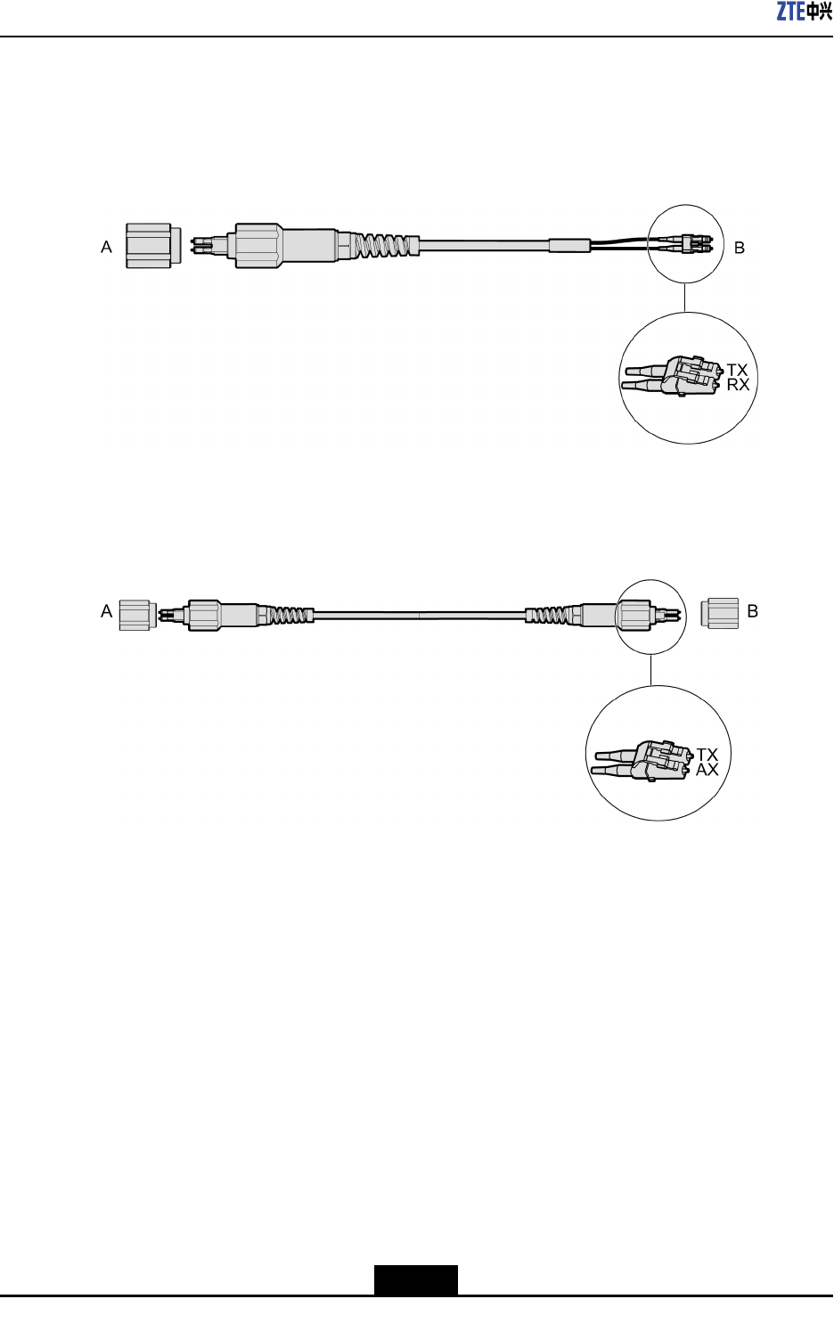
AnSMFcableisusedtoconnecttheZXSDRR8882toaBBU.EndAismountedwitha
waterproofLCconnectorwhileendBismountedwithanLCconnector,seeFigure4-4.
Figure4-4FiberCableforConnectinganRRUtoaBBU
AnSMFcablewithbothendsmountedwithawaterproofLCconnectorisusedtoconnect
twoRRUs,seeFigure4-5.
Figure4-5FiberCableforCascadingRRUs
SignalDenition
None
Connections
ThecableconnectionsbetweenanRRUandaBBUaredescribedasfollows:
lEndAisconnectedtoanopticalinterface(OPT1,OPT2,orOPT3)ontheZXSDR
R8882.
lEndBisconnectedtoanappropriateopticalinterfaceontheBBU.
ThecableconnectionsbetweentwocascadedRRUsaredescribedasfollows:
lEndAisconnectedtoanopticalinterface(OPT1,OPT2,orOPT3)onaZXSDR
R8882.
lEndBisconnectedtoanopticalinterface(OPT1,OPT2,orOPT3)ontheother
ZXSDRR8882.
4-4
SJ-20150104112914-002|2015-01-04(R1.0)ZTEProprietaryandCondential
Chapter4ExternalCables
4.5ExternalMonitoringCable
Function
TheexternalmonitoringcablesupportssignalinteractionbetweentheZXSDRR8882
systemandexternaldevices,includingtheinteractionofalarmsignals,RS485/RS422
controlsignals,anddrycontactsignals.
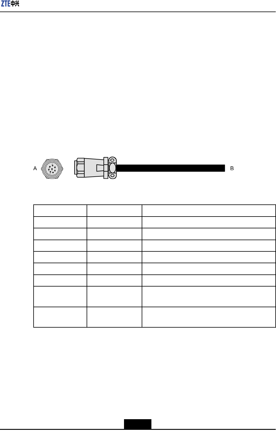
ExternalView
Figure4-6showstheexternalviewofanexternalmonitoringcable.EndAismountedwith
an8-pinroundplug.EndBneedstobemountedwithanappropriateconnectoronsite
accordingtotheconnectortypeoftheexternaldevicetobeconnected.Thecablelength
is1.2m.
Figure4-6ExternalMONInterfaceCable
SignalDenition
PinNameDenition
PIN1Dry_Node_In1+Drycontactinput,positive
PIN2Dry_Node_In1-Drycontactinput,negative
PIN3Dry_Node_In2+Drycontactinput,positive
PIN4Dry_Node_In2-Drycontactinput,negative
PIN5RS485TX+Full-duplexRS422/RS485TX+(differentialmode)
PIN6RS485TX-Full-duplexRS422/RS485TX-(differentialmode)
PIN7RS485RX+Full-duplexRS422/RS485RX+(differentialmode)or
half-duplexRS485A
PIN8RS485RX-Full-duplexRS422/RS485RX-(differentialmode)or
half-duplexRS485B
Connections
lEndAisconnectedtotheMONinterfaceoftheZXSDRR8882.
lEndBisconnectedtoanexternalmonitoringdeviceoradrycontactdevice.
4-5
SJ-20150104112914-002|2015-01-04(R1.0)ZTEProprietaryandCondential
ZXSDRR8882HardwareDescription
4.6AISGControlCable
Function
TheAISGcontrolcableisusedtosendAISGcontrolsignalstoaRETantennathatis
connectedtotheZXSDRR8882.
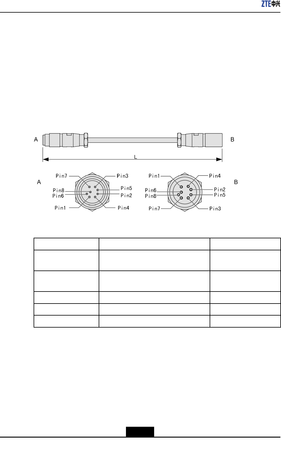
ExternalView
An8-pinaviationplugincompliancewithIEC60130-9-EDismountedonbothendsofthe
AISGcontrolcable,seeFigure4-7.
Figure4-7AISGControlCable
SignalDescription
NameDenitionPin
AISG_RS485BRS485signalpositive(RS485Bspecied
inAISG)
PIN3
AISG_RS485ARS485signalnegative(RS485Aspecied
inAISG)
PIN5
AISG_PWRDCpower(output)PIN6
GNDPDCpowerground(output)PIN7
NCNotusedPIN1,PIN2,PIN4,PIN8
Connections
lEndAisconnectedtotheAISGinterfaceoftheZXSDRR8882chassis.
lEndBisconnectedtothecontrolinterfaceofanRETantenna.
4-6
SJ-20150104112914-002|2015-01-04(R1.0)ZTEProprietaryandCondential

Figures
Figure1-1ZXSDRR8882WithTwoOpticalInterfaces.............................................1-1
Figure1-2ZXSDRR8882WithThreeOpticalInterfaces...........................................1-2
Figure2-1ExternalInterfacesattheBottom(ZXSDRR8882WithTwoOptical
Interfaces)..............................................................................................2-1
Figure2-2ExternalInterfaceattheRightSide(ZXSDRR8882WithTwoOptical
Interfaces)..............................................................................................2-2
Figure2-3ExternalInterfacesattheBottom(ZXSDRR8882WithThreeOptical
Interfaces)..............................................................................................2-4
Figure2-4ExternalInterfaceattheRightSide(ZXSDRR8882WithThreeOptical
Interfaces)..............................................................................................2-5
Figure3-1IndicatorsoftheZXSDRR8882WithTwoOpticalInterfaces...................3-1
Figure3-2IndicatorsoftheZXSDRR8882WithThreeOpticalInterfaces.................3-2
Figure4-1ProtectiveGroundingCable.....................................................................4-1
Figure4-2DCPowerInputCable.............................................................................4-2
Figure4-3AntennaFeederCable.............................................................................4-3
Figure4-4FiberCableforConnectinganRRUtoaBBU..........................................4-4
Figure4-5FiberCableforCascadingRRUs.............................................................4-4
Figure4-6ExternalMONInterfaceCable.................................................................4-5
Figure4-7AISGControlCable.................................................................................4-6
I
SJ-20150104112914-002|2015-01-04(R1.0)ZTEProprietaryandCondential

Figures
Thispageintentionallyleftblank.
II
SJ-20150104112914-002|2015-01-04(R1.0)ZTEProprietaryandCondential

Tables
Table2-1ExternalInterfaces(ZXSDRR8882WithTwoOpticalInterfaces)..............2-2
Table2-2ExternalInterfaces(ZXSDRR8882WithThreeOpticalInterfaces)............2-5
Table3-1IndicatorDescription(V4.09.21/V4.11.10)..................................................3-2
Table3-2IndicatorDescription(V4.12).....................................................................3-4
III
SJ-20150104112914-002|2015-01-04(R1.0)ZTEProprietaryandCondential

Tables
Thispageintentionallyleftblank.
IV
SJ-20150104112914-002|2015-01-04(R1.0)ZTEProprietaryandCondential

Glossary
AISG
-AntennaInterfaceStandardsGroup
BBU
-BaseBandUnit
DIN
-DeutschesInstitutfürNormung(=GermanInstituteforStandardization)
PCB
-PrintedCircuitBoard
RET
-RemoteElectricalTilt
RF
-RadioFrequency
SMF
-SingleModeFiber
V
SJ-20150104112914-002|2015-01-04(R1.0)ZTEProprietaryandCondential