Zebex BRC-RS90 Bluetooth communication cradle User Manual
Zebex Industries Inc Bluetooth communication cradle
UserManual.wiki
>
Zebex
>
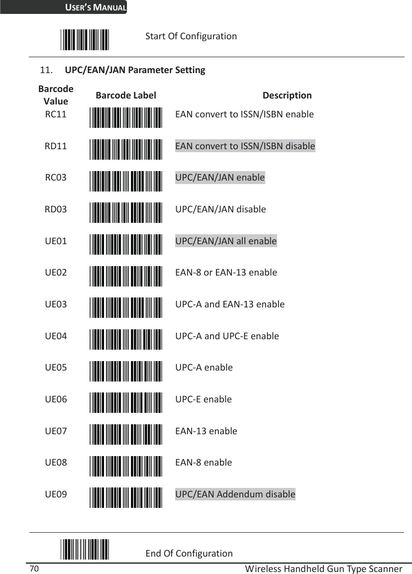
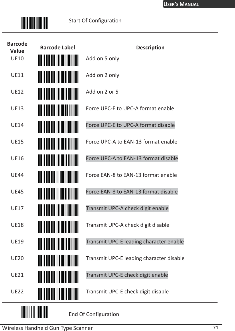
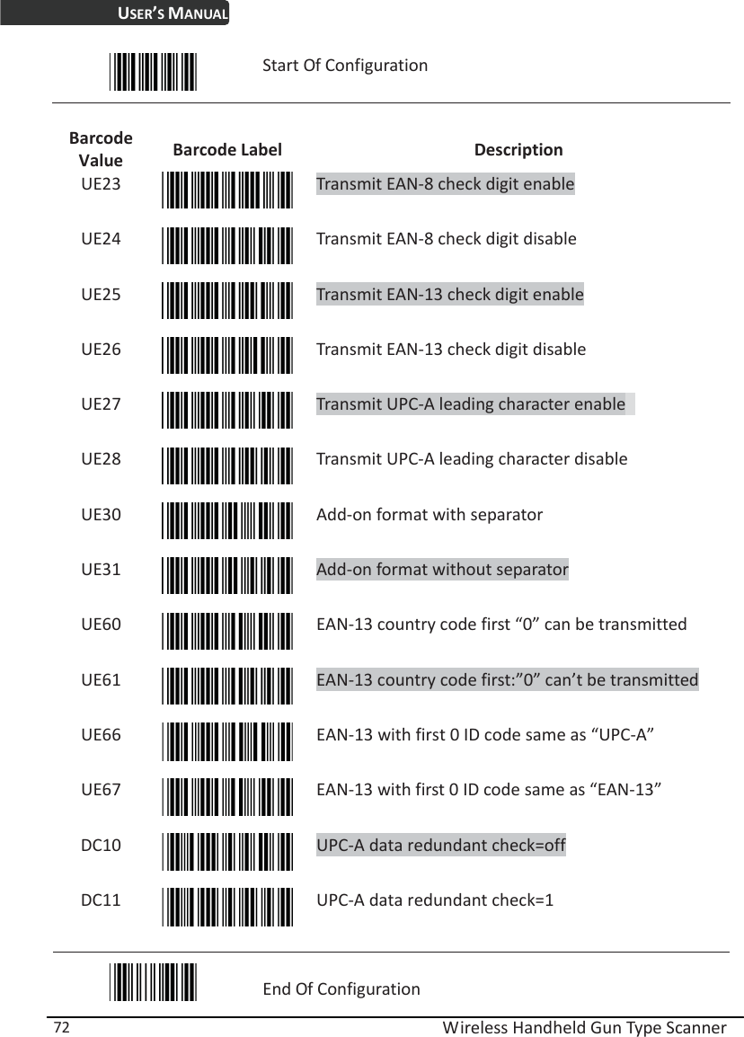
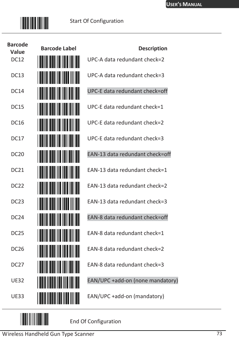
BRC RS90 User Manual
user manual
Navigation menu
Upload a User Manual
Namespaces
Wiki Guide
HTML
PDF
Info
Views
User Manual
Discussion / Help
Navigation

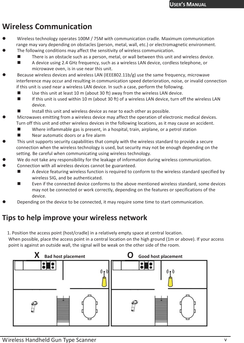
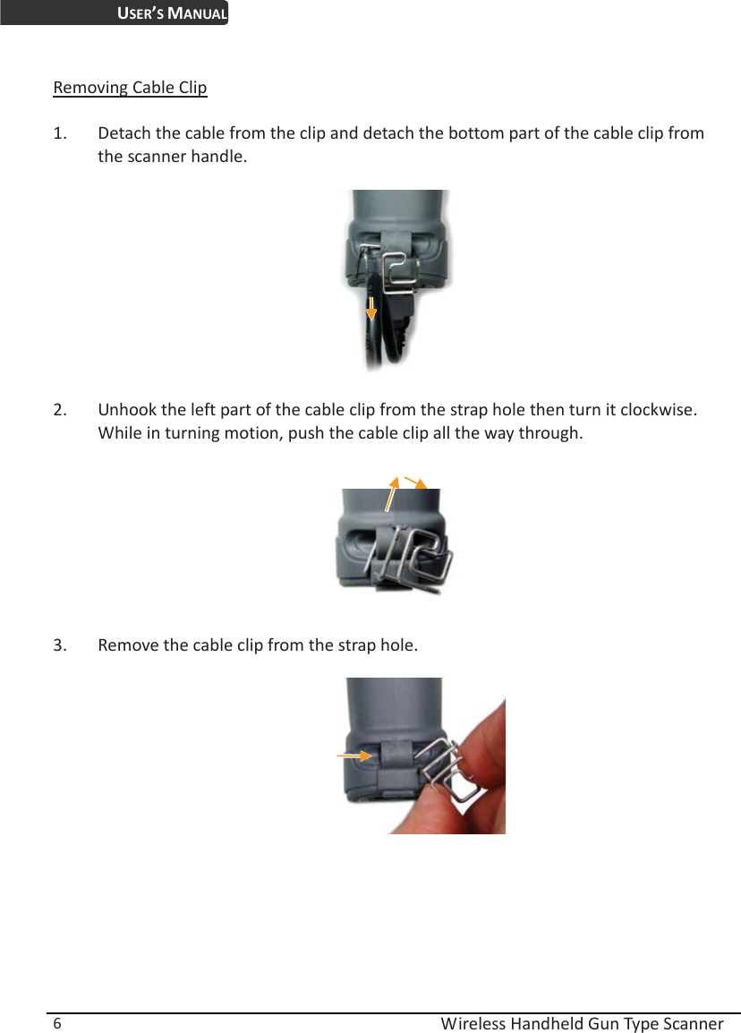
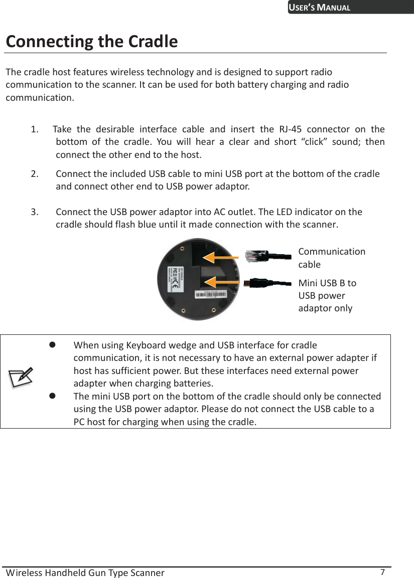
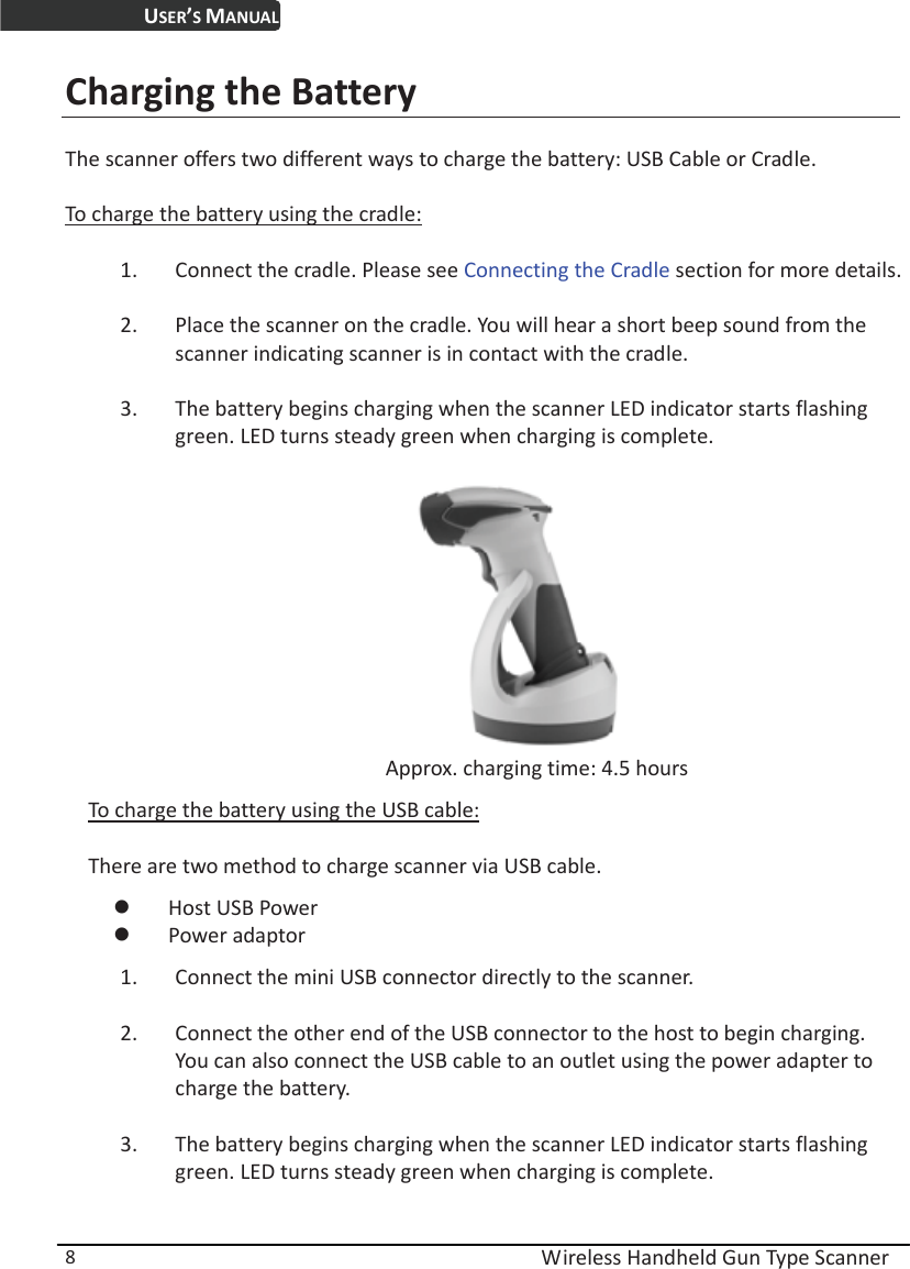
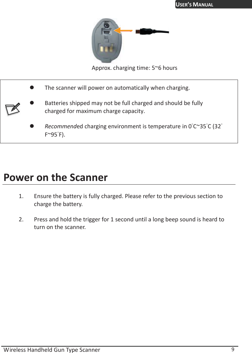
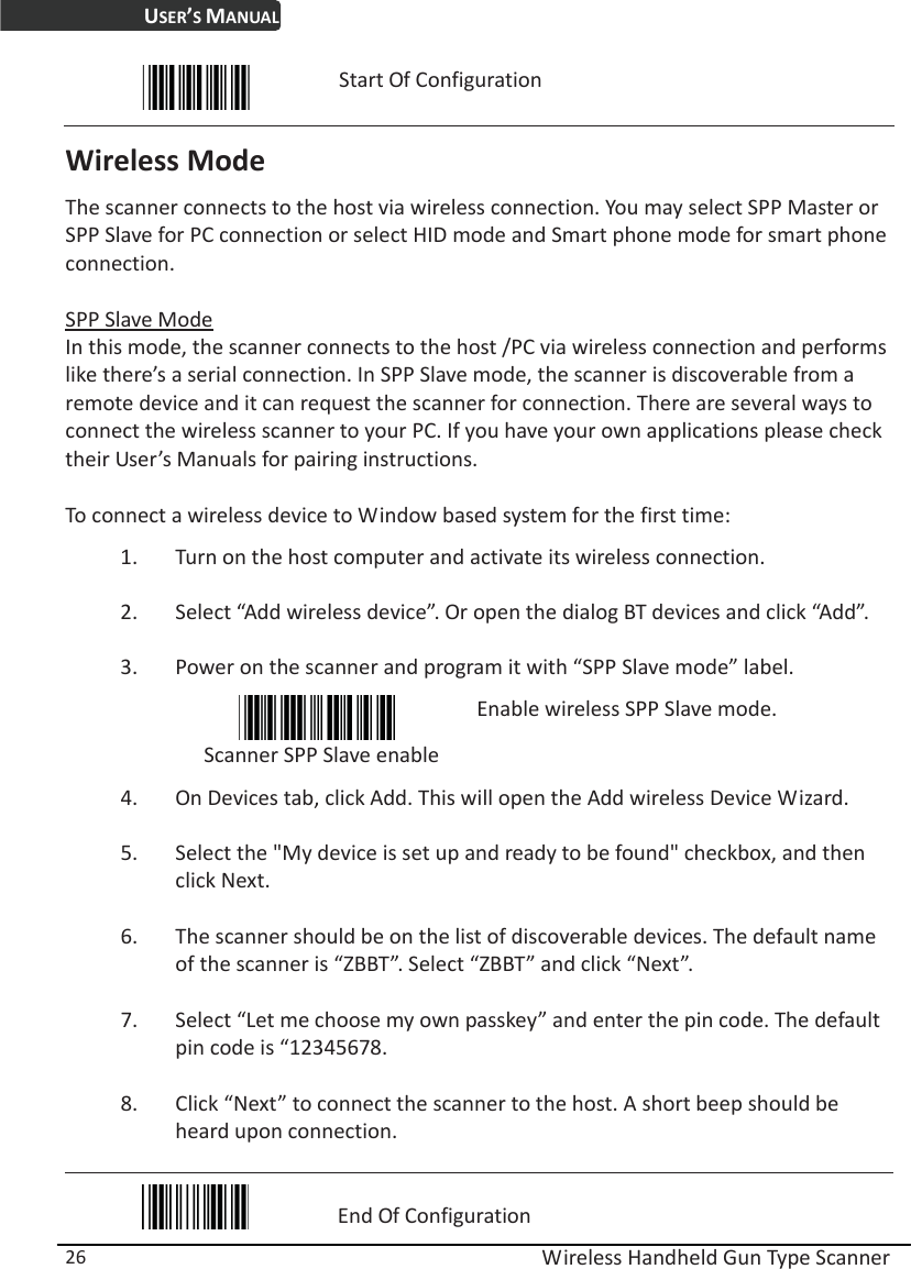
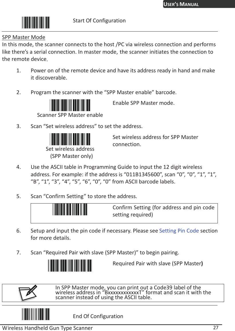
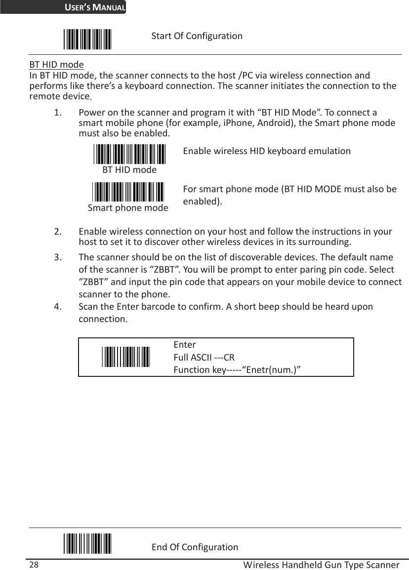
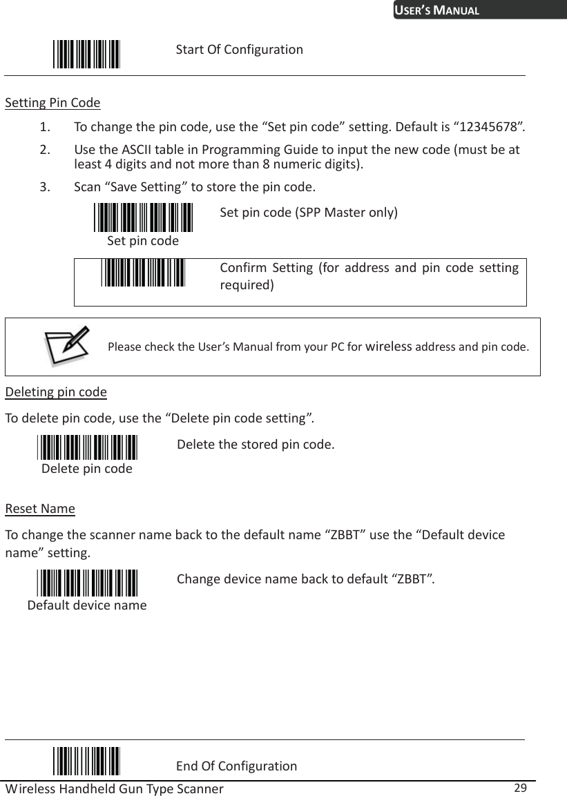
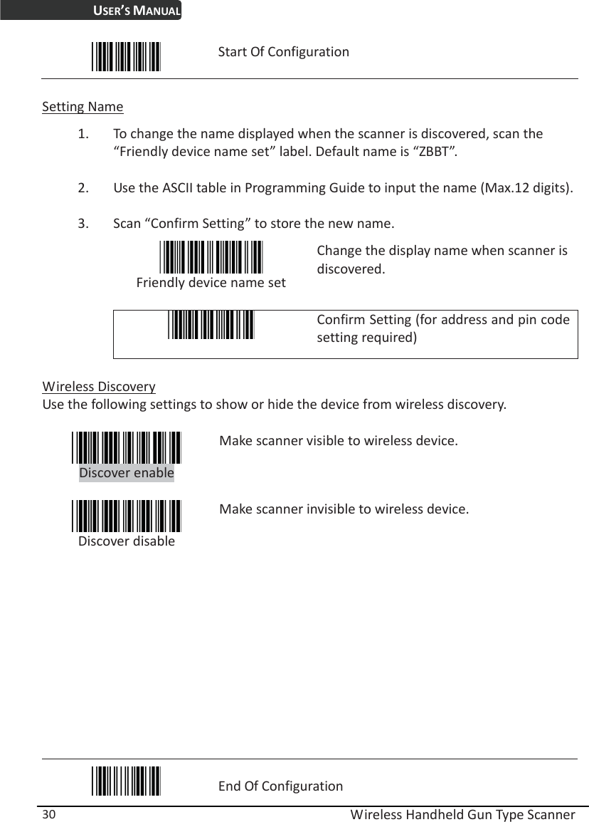
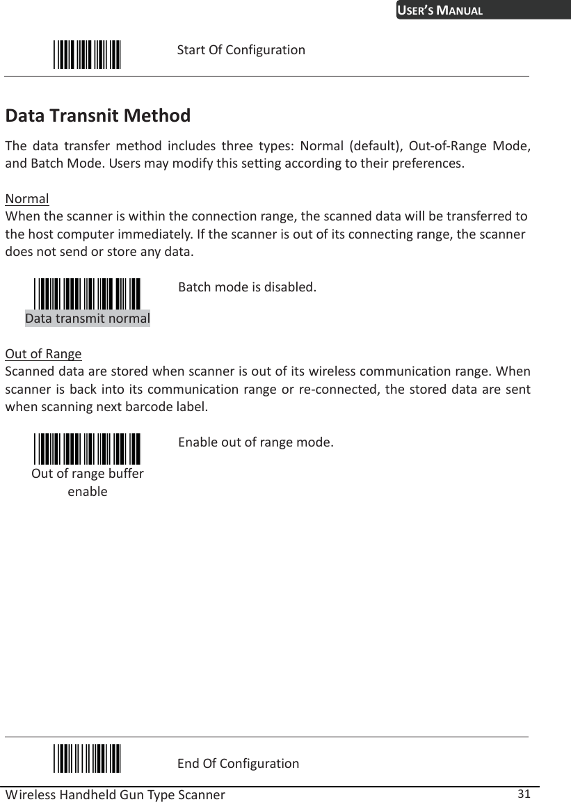
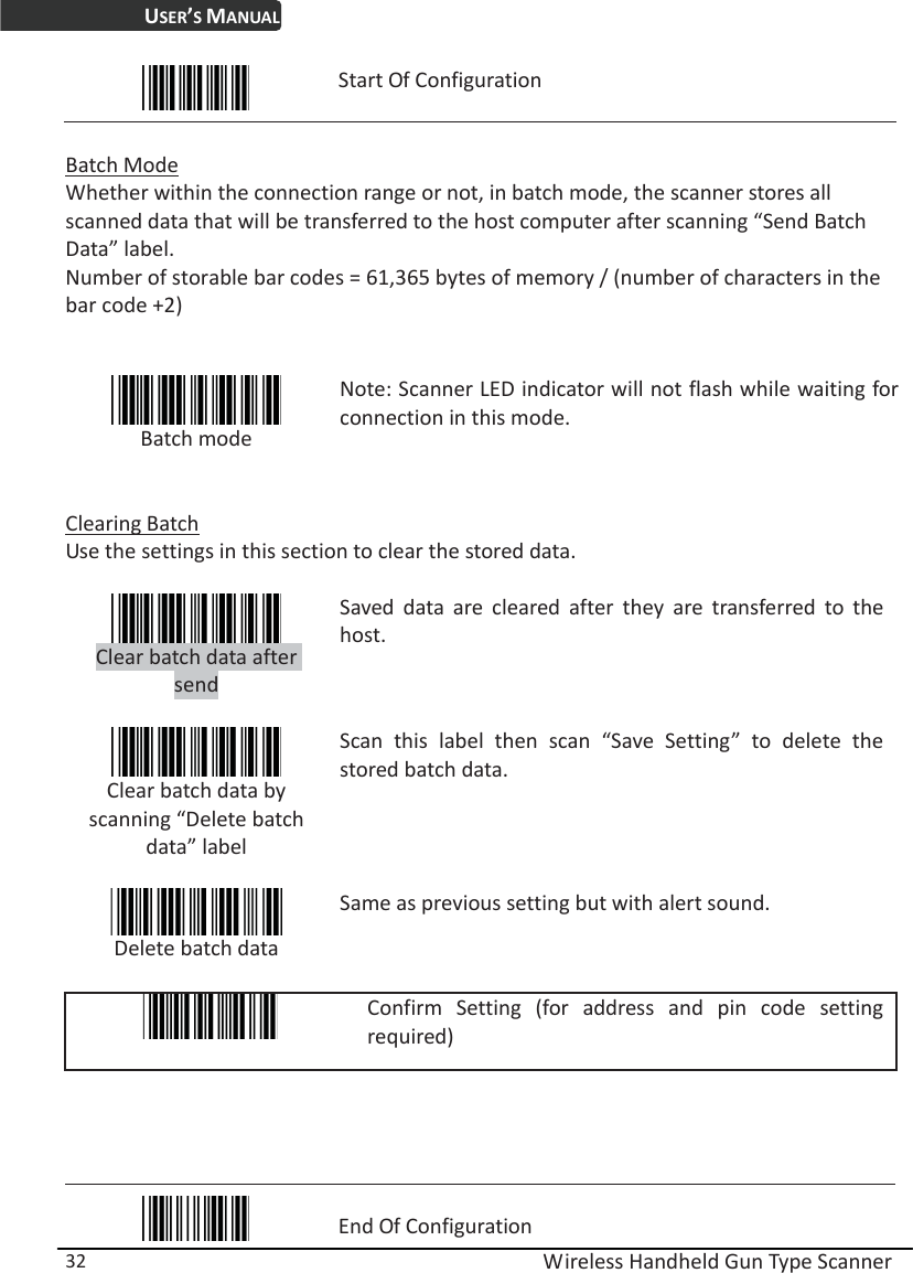
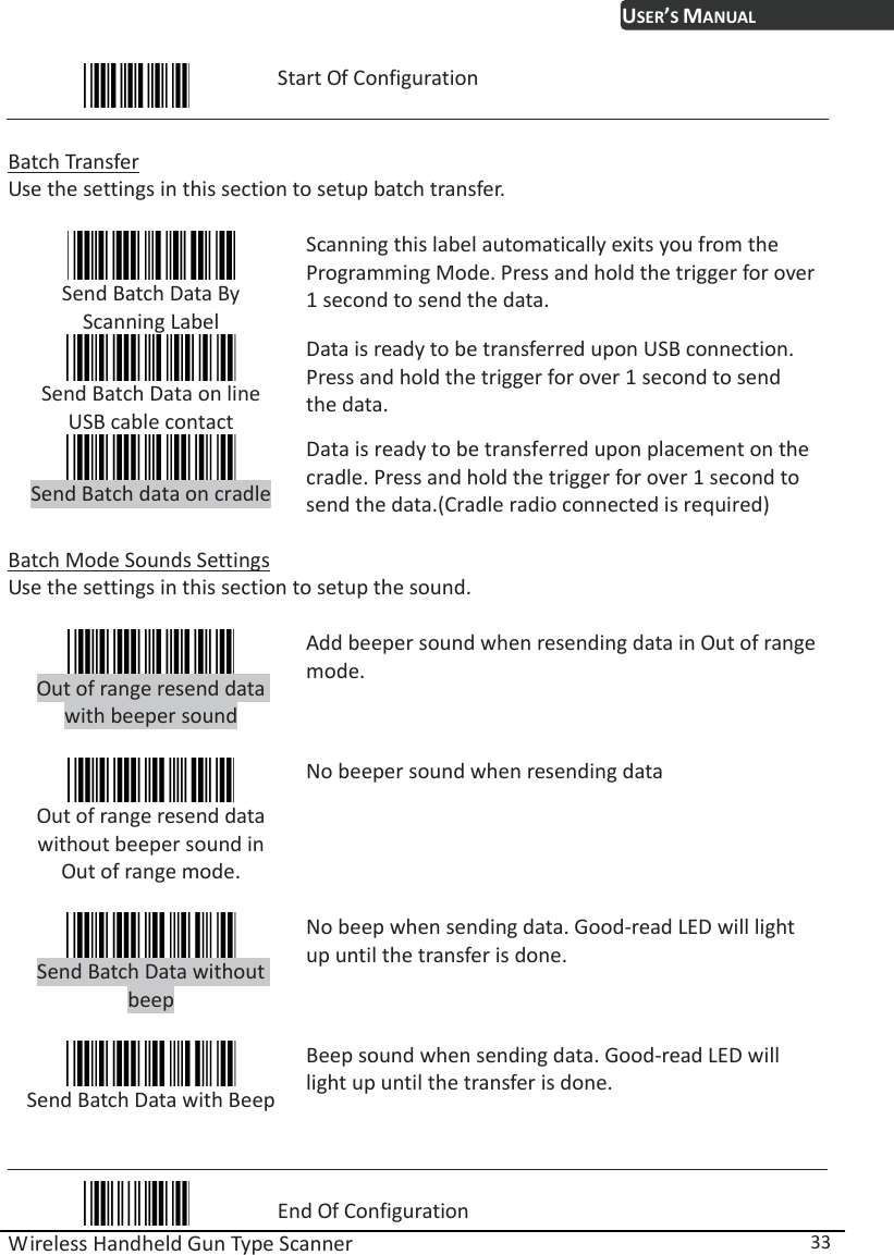
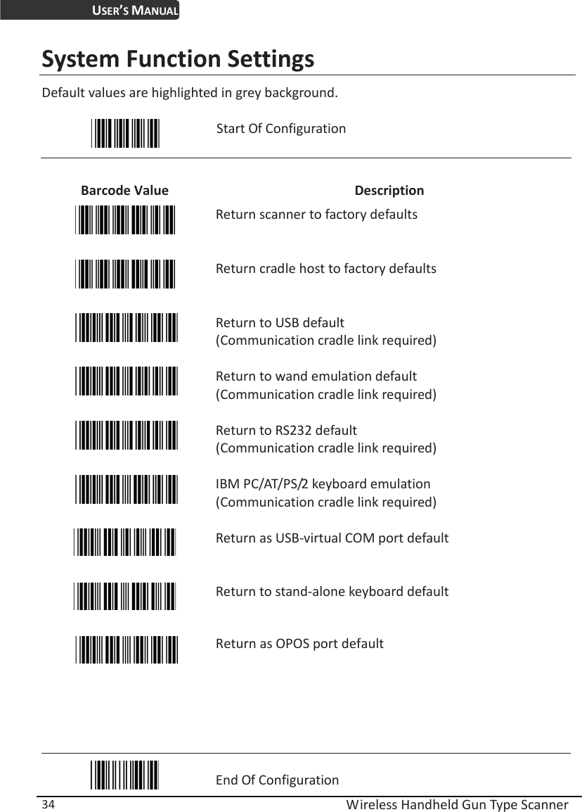
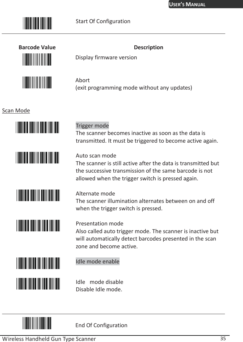
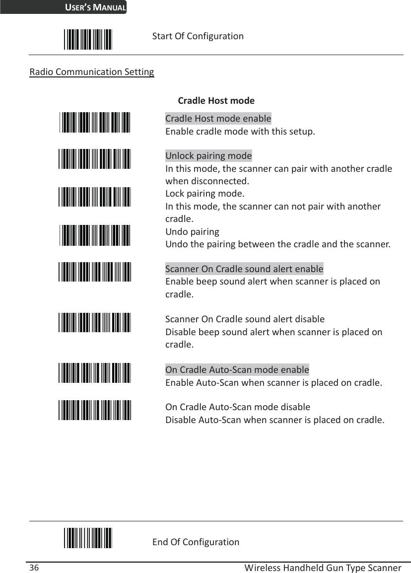
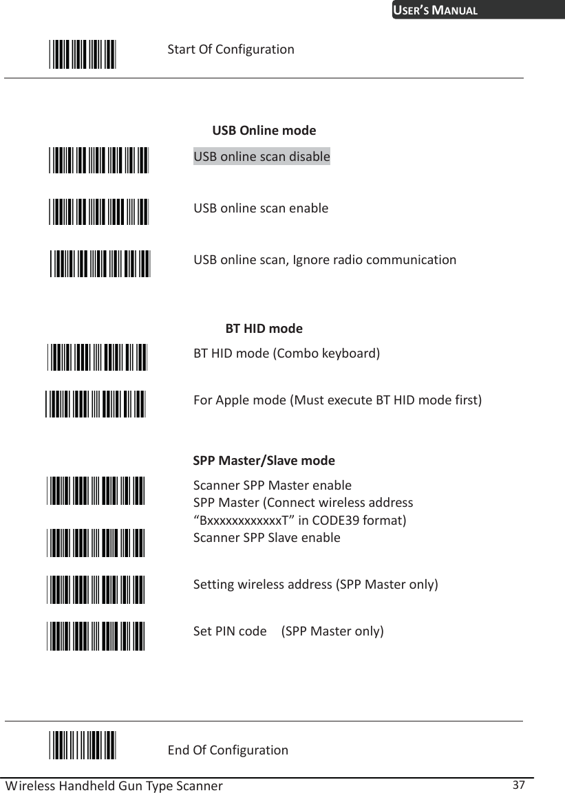
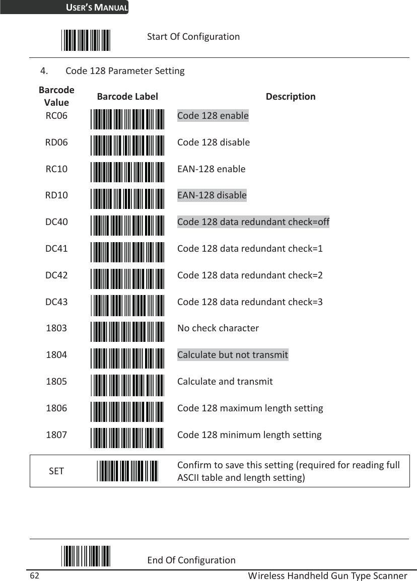
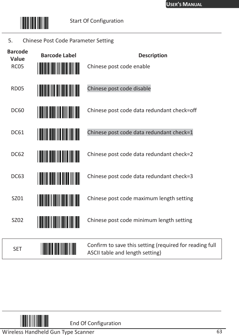
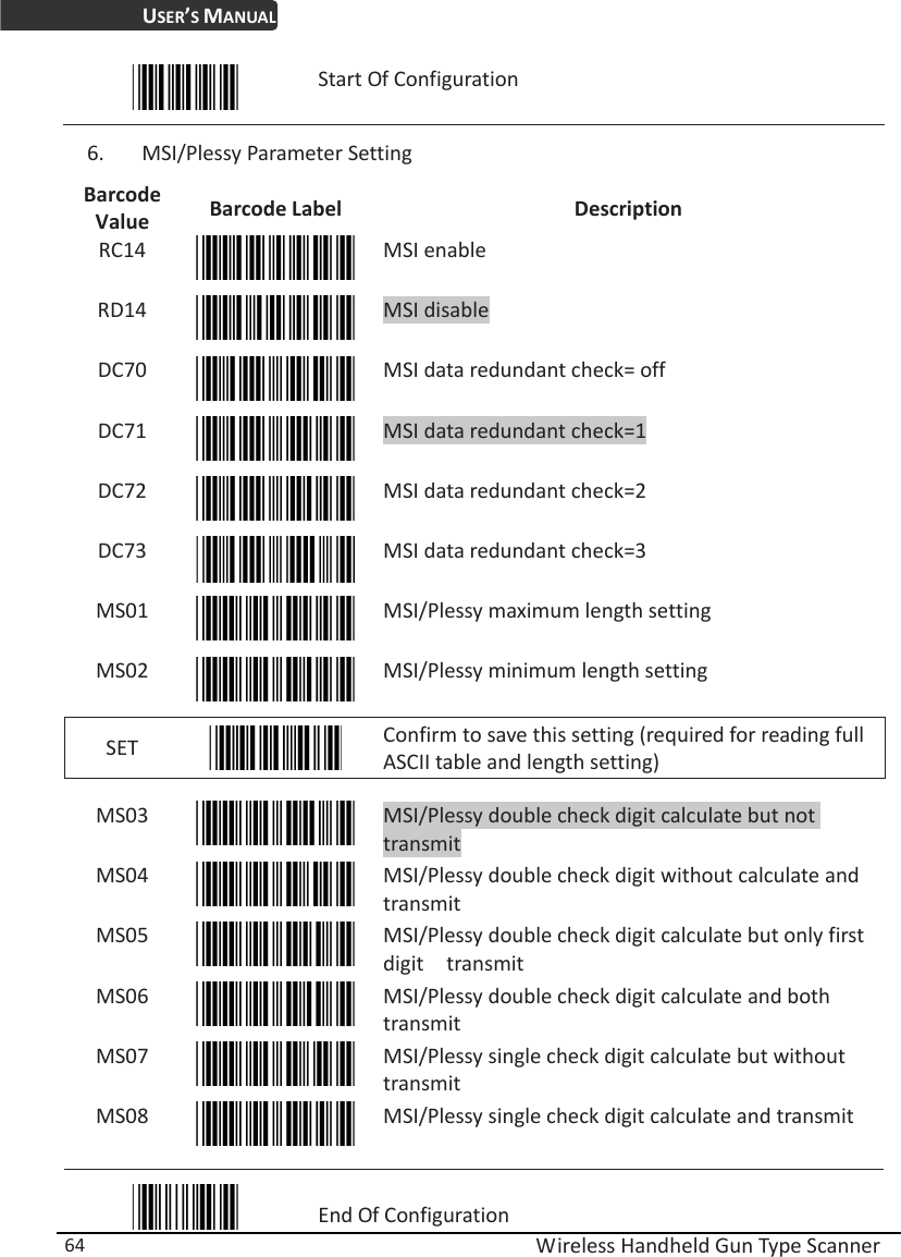
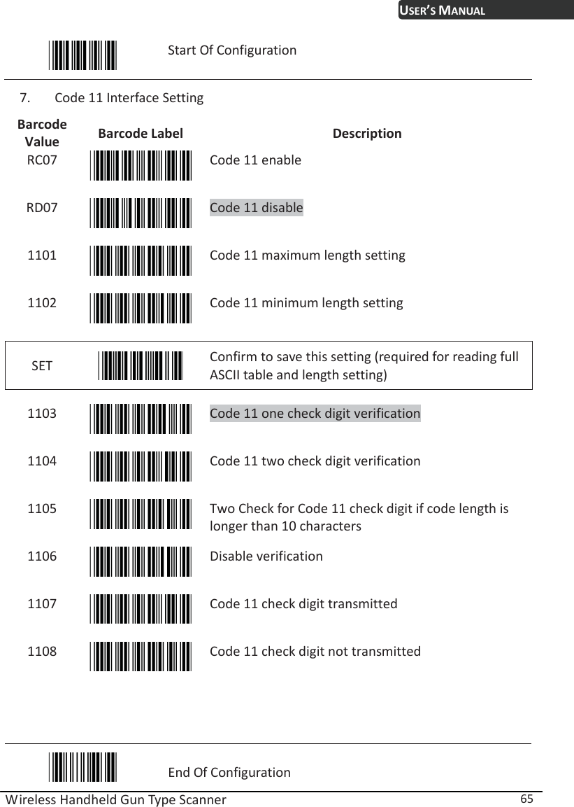
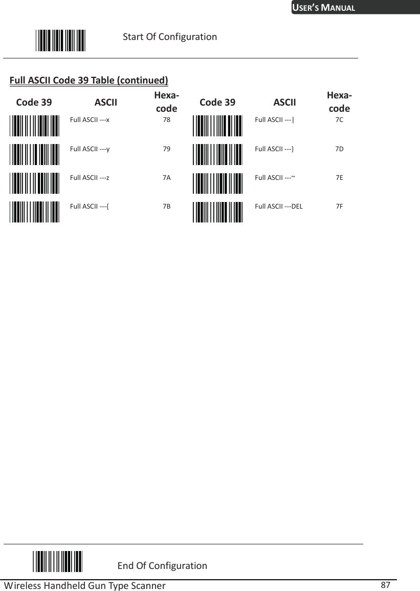
![USER’S MANUAL Wireless Handheld Gun Type Scanner 86 Start Of Configuration Full ASCII Code 39 Table (continued) Code 39 ASCII Hexa-code Code 39 ASCII Hexa-code Full ASCII ---Z 5A Full ASCII ---i 69 Full ASCII ---[ 5B Full ASCII ---j 6A Full ASCII ---\ 5C Full ASCII ---k 6B Full ASCII ---] 5D Full ASCII ---l 6C Full ASCII ---^ 5E Full ASCII ---m 6D Full ASCII ---_ 5F Full ASCII ---n 6E Full ASCII ---` 60 Full ASCII ---o 6F Full ASCII ---a 61 Full ASCII ---p 70 Full ASCII ---b 62 Full ASCII ---q 71 Full ASCII ---c 63 Full ASCII ---r 72 Full ASCII ---d 64 Full ASCII ---s 73 Full ASCII ---e 65 Full ASCII ---t 74 Full ASCII ---f 66 Full ASCII ---u 75 Full ASCII ---g 67 Full ASCII ---v 76 Full ASCII ---h 68 Full ASCII ---w 77 End Of Configuration](https://usermanual.wiki/Zebex/BRC-RS90/User-Guide-1723737-Page-96.png)