Zebex BRC-RS90 Bluetooth communication cradle User Manual
Zebex Industries Inc Bluetooth communication cradle
Zebex >
user manual

Advanced Handheld High-Speed Laser Scanner 1

This device complies with Part 15 of the FCC Rules. Operation is subject to the following two
conditions:
(1) This device may not cause harmful interference.
(2)This device must accept any interference received, including interference that may cause
undesired operation.
15.105 Federal Communications Commission (FCC) Requirements, Part 15
This equipment has been tested and found to comply with the limits for a class B digital
device, pursuant to part 15 of the FCC Rules. These limits are designed to provide
reasonable protection against harmful interference in a residential installation.
This equipment generates, uses and can radiate radio frequency energy and, if not
installed and used in accordance with the instructions, may cause harmful interference
to radio communications. However, there is no guarantee that interference will not
occur in a particular installation. If this equipment does cause harmful interference to
radio or television reception, which can be determined by turning the equipment off and
on, the user is encouraged to try to correct the interference by one or more of the
following measures:
---Reorient or relocate the receiving antenna.
---Increase the separation between the equipment and receiver.
---Connect the equipment into an outlet on a circuit different from that to which the
receiver is connected.
---Consult the dealer or an experienced radio/TV technician for help.

Wireless Handheld Gun Type Scanner i
USER’S MANUAL
User’s Manual
Z-3190BT, Z-3191BT, Z3192BT Wireless Barcode Scanner
CR-90, RS-90 Charging & RF Communication Station
Revision History
Changes to the original manual are listed below:
Version Date Description of Version
1.0 August. 24, 2011 Initial release
1.1 March. 26, 2012 Added wireless communication tips
1.2 April. 18, 2012 Added cable clip installation and Smart Phone
Software Keypad Control Setting
1.3 May. 24, 2012 Added pin-out configuration and cable pin-out
1.4 June. 1 2012 Removed the charging cradle section

Wireless Handheld Gun Type Scanner
ii
USER’S MANUAL
Important Notice
No warranty of any kind is made in regard to this material, including, but not limited to,
implied warranties of merchantability or fitness for any particular purpose. We are not
liable for any errors contained herein nor for incidental or consequential damages in
connection with furnishing, performance or use of this material. We shall be under no
liability in respect of any defect arising from fair wear and tear, willful damage,
negligence, abnormal working conditions, failure to follow the instructions and warnings,
or misuse or alteration or repair of the products without written approval. No part of this
document may be reproduced, transmitted, stored in a retrieval system, transcribed, or
translated into any human or computer or other language in any form or by any means
electronic, mechanical, magnetic, optical, chemical, biological, manual or otherwise,
except for brief passages which may be quoted for purposes of scholastic or literary
review, without express written consent and authorization. We reserve the right to make
changes in product design without reservation and without notification. The material in
this guide is for information only and is subject to change without notice. All trademarks
mentioned herein, registered or otherwise, are the properties of their various, ill,
assorted owners.
General Handling Precautions
Do not dispose the scanner in fire.
Do not put the scanner directly in the sun or by any heat source.
Do not use or store the scanner in a very humid place.
Do not drop the scanner or allow it to collide violently with other objects.
Do not take the scanner apart without authorization
Guidance for Printing
This manual is in A5 size. Please double check your printer setting before printing it out.
When the barcodes are to be printed out for programming, the use of a high-resolution
laser printer is strongly suggested for the best scan result.
Copyright © 2012. All rights reserved.

USER’S MANUAL
Radio Notice
This equipment generates uses and can radiate radio frequency energy. If not installed
and used in accordance with the instructions in this manual, it may cause interference to
radio communications. The equipment has been tested and found to comply with the
limits for a Class B computing device pursuant to EN55022 and 47 CFR, Part 2 and Part 15
of the FCC rules. These specifications are designed to provide reasonable protection
against interference when operated in a commercial environment.
Radio and Television Interference
Operation of this equipment in a residential area can cause interference to radio or
television reception. This can be determined by turning the equipment off and on.
The user is encouraged to try to correct the interference by one or more of the following
measures:
- Reorient the receiving antenna.
- Relocate the device with respect to the receiver.
- Move the device away from the receiver.
- Plug the device into a different outlet so that the device and the receiver are on
different branch circuits.
If necessary the user may consult the manufacturer, and authorized dealer, or
experienced radio/television technician for additional suggestions. The user may find
the following booklet prepared by the Federal Communications Commission helpful:
“How to Identify and Resolve Radio-TV Interference Problems.” This booklet is available
from the U.S. Government Printing Office, Washington, DC 20402 U.S.A., Stock No.
04000003454. 0
Laser Safety
This equipment generates, uses, and can radiate radio frequency energy. If not installed
and used in accordance with the instructions in this manual, it may cause interference to
radio communications. The equipment has been tested and found to comply with the
limits for a Class B computing device pursuant to EN55022 and 47 CFR, Part 2 and Part 15
of FCC Rules. These specifications are designed to provide reasonable protection against
interference when operated in a commercial environment.
Radiant Energy: The laser scanner uses one low-power visible laser diodes operating at
650nm in an opto-mechanical scanner resulting in less than 3.9ʅW radiated power as
observed through a 7mm aperture and averaged over 10 seconds.
Do not attempt to remove the protective housing of the scanner, as unscanned laser light
with a peak output up to 0.8mW would be accessible inside.
Wireless Handheld Gun Type Scanner iii

Wireless Handheld Gun Type Scanner
iv
USER’S MANUAL
Laser Light Viewing: The scan window is the only aperture through which laser light may
be observed from this product. A failure of the scanner engine, while the laser diode
continues to emit a laser beam, may cause emission levels to exceed those for safe
operation. The scanner has safeguards to prevent this occurrence. If, however, a
stationary laser beam is emitted, the failing scanner should be disconnected from its
power source immediately.
Adjustments: Do not attempt any adjustments or alteration of this product. Do not
remove the protective housing of the scanner. There are no user-serviceable parts inside.
Optical: The use of optical instruments with this product will increase the eye hazard.
Optical instruments include binoculars, magnifying glasses, and microscopes but do not
include normal eye glasses worn by the user.
CAUTION: Use of controls or adjustments or performance of procedures other than those
specified herein may result in hazardous radiation exposure.
For CE-Countries
This scanner is in conformity with CE standards. Please note that an approved, CE-marked
power supply unit should be used in order to maintain CE conformance.
Power Supply
z Use only the type of battery and the charging equipments that came with your
scanner.
z Using any other type of battery and charging equipment may damage the scanner
and invalidate the warranty.
z Do not short the battery terminals. The battery could overheat.
z Do not attempt to split or peel the outer casing.
z Remove the battery if the scanner is not going to be used for a long time. If the
battery is left unused for more than 3 months, you need to charge the battery
before use.

USER’S MANUAL
Wireless Handheld Gun Type Scanner v
Wireless Communication
z Wireless technology operates 100M / 75M with communication cradle. Maximum communication
range may vary depending on obstacles (person, metal, wall, etc.) or electromagnetic environment.
z The following conditions may affect the sensitivity of wireless communication.
There is an obstacle such as a person, metal, or wall between this unit and wireless device.
A device using 2.4 GHz frequency, such as a wireless LAN device, cordless telephone, or
microwave oven, is in use near this unit.
z Because wireless devices and wireless LAN (IEEE802.11b/g) use the same frequency, microwave
interference may occur and resulting in communication speed deterioration, noise, or invalid connection
if this unit is used near a wireless LAN device. In such a case, perform the following.
Use this unit at least 10 m (about 30 ft) away from the wireless LAN device.
If this unit is used within 10 m (about 30 ft) of a wireless LAN device, turn off the wireless LAN
device.
Install this unit and wireless device as near to each other as possible.
z Microwaves emitting from a wireless device may affect the operation of electronic medical devices.
Turn off this unit and other wireless devices in the following locations, as it may cause an accident.
Where inflammable gas is present, in a hospital, train, airplane, or a petrol station
Near automatic doors or a fire alarm
z This unit supports security capabilities that comply with the wireless standard to provide a secure
connection when the wireless technology is used, but security may not be enough depending on the
setting. Be careful when communicating using wireless technology.
z We do not take any responsibility for the leakage of information during wireless communication.
z Connection with all wireless devices cannot be guaranteed.
A device featuring wireless function is required to conform to the wireless standard specified by
wireless SIG, and be authenticated.
Even if the connected device conforms to the above mentioned wireless standard, some devices
may not be connected or work correctly, depending on the features or specifications of the
device.
z Depending on the device to be connected, it may require some time to start communication.
Tips to help improve your wireless network
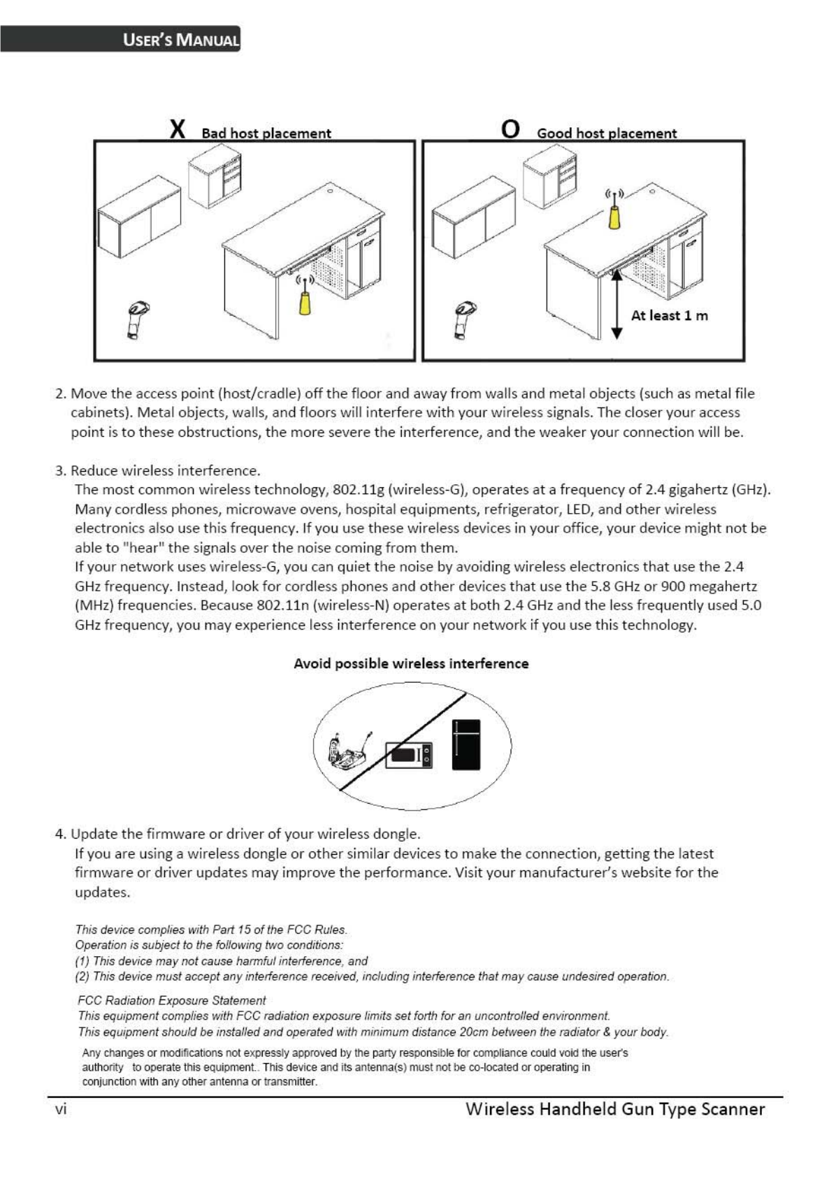
1. Position the access point (host/cradle) in a relatively empty space at central location.
When possible, place the access point in a central location on the high ground (1m or above). If your access
point is against an outside wall, the signal will be weak on the other side of the room.
X Bad host placement O Good host placement

Wireless Handheld Gun Type Scanner vii
USER’S MANUAL
Table of Contents
Important Notice..................................................................................................................ii
General Handling Precautions..............................................................................ii
Guidance for Printing ...........................................................................................ii
Laser Safety .........................................................................................................iii
For CE-Countries..................................................................................................iv
Power Supply ......................................................................................................iv
Wireless Communication .....................................................................................v
Introduction .........................................................................................................................1
Product Overview ........................................................................................................2
Scanner ................................................................................................................2
Cradle ...................................................................................................................2
Scanner and Accessories..............................................................................................3
Battery Installation.......................................................................................................4
Installing Cable Clip......................................................................................................5
Connecting the Cradle..................................................................................................7
Charging the Battery ....................................................................................................8
Power on the Scanner..................................................................................................9
How to Scan ...............................................................................................................10
Radio Communication Host Type...............................................................................11
Cradle Host Mode ..............................................................................................11
SPP Mater/SPP Slave Mode................................................................................11
HID Mode ...........................................................................................................11
Paging the Scanner.....................................................................................................12
Scanner USB online to Host .......................................................................................12
USB Online Mode...............................................................................................12
Visible Indicators........................................................................................................13
Scanner ..............................................................................................................13
Cradle .................................................................................................................14
Sound Indicators ........................................................................................................14
ACK/NAK Protocol or Frame Packing..........................................................................15
Scanner to Remote Application..................................................................................16
Pin-out Configuration.................................................................................................18
Cable Pin-out..............................................................................................................19
Programming Guide ...........................................................................................................20
Connecting to a Host..................................................................................................24
Cradle Host Mode ..............................................................................................25
Wireless Mode...................................................................................................26
Data Transnit Method ........................................................................................31
System Function Settings ...........................................................................................34
Data Editing........................................................................................................80
Appendix 1: USB Virtual COM Driver Installation ..............................................88
Appendix 2: Barcode Length Setting ..................................................................89

Wireless Handheld Gun Type Scanner 1
USER’S MANUAL
Introduction
This scanner is a gun type rugged wireless CCD/Laser barcode scanner with a state of
the art scan engine. Featuring a superb scanning speed and able to withstand 1.5
meter drop, it is ideal for manufacturing and logistic sectors.
The cradle, a dongle, or devices with wireless technology can be the host of this
scanner. All scanned data are instantly transferred to the connected host in a 100-
meter connection range in open space or 75-meter range in indoor environments (the
actual communication range may vary due to different indoor placement). This feature
eliminates hazardous cables and creates a safer work environment.
Either scanning in the handheld or hands-free mode, this scanner always offers a high-
accuracy and reliable scanning ability. This scanner would be your trusted tool
scanning partner.
Key Features:
z Superb scanning ability
z Proprietary hardware decoding technology
z 100M long-range wireless connection
z Rugged and ergonomic form factor
z Flexible communications
USER’S MANUAL
Wireless Handheld Gun Type Scanner
2
Product Overview
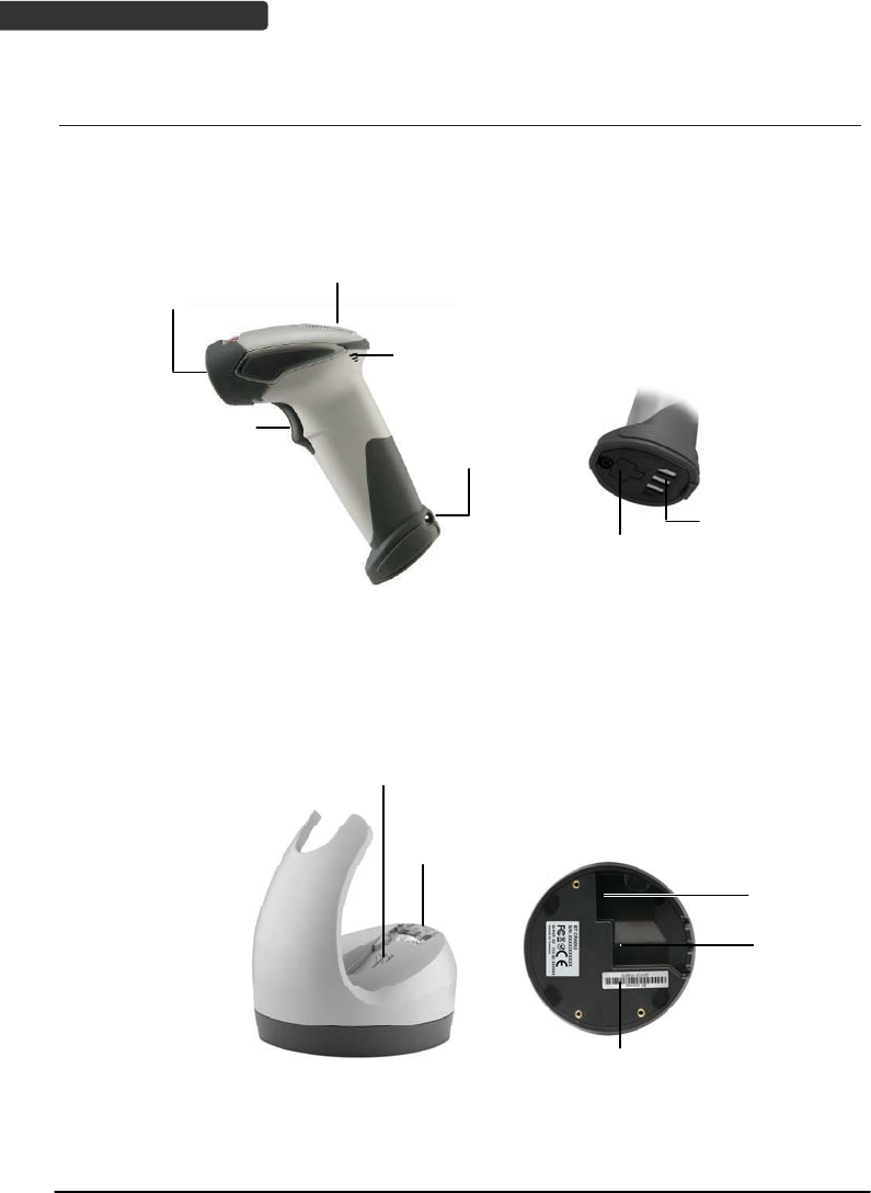
Scanner
LED Indicator
Exit Window
Buzzer
Metal Charging
Contacts
Trigger Strap Hole
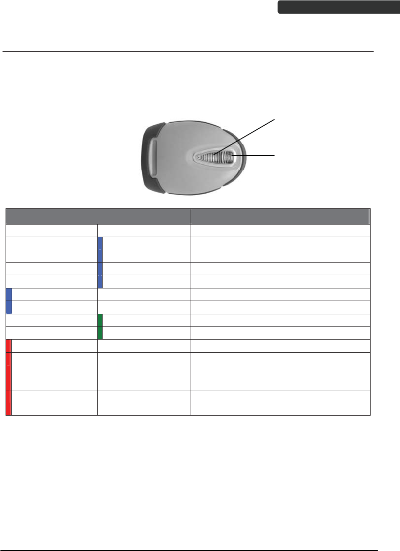
Cradle
Function
Trigger/LED
indicator
Charging
Contacts
Host
Connector
DC Power
Connector
Cable Connector
Bluetooth
Address Label
USER’S MANUAL
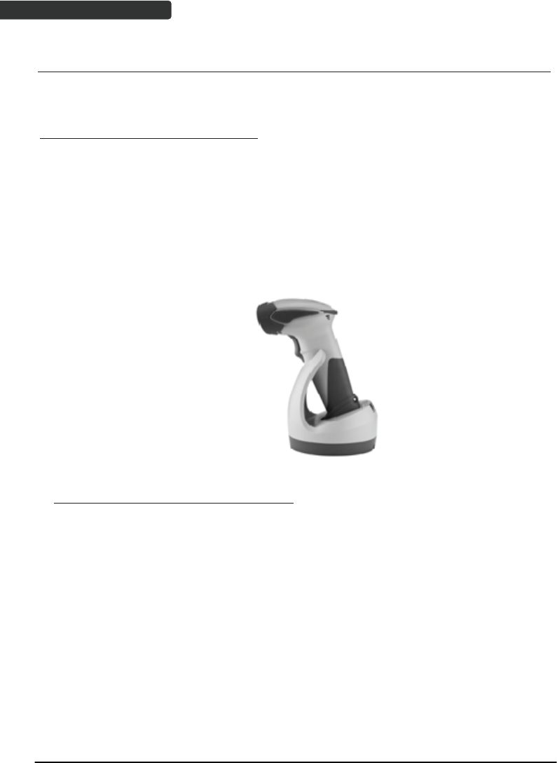
Wireless Handheld Gun Type Scanner 3
Scanner and Accessories
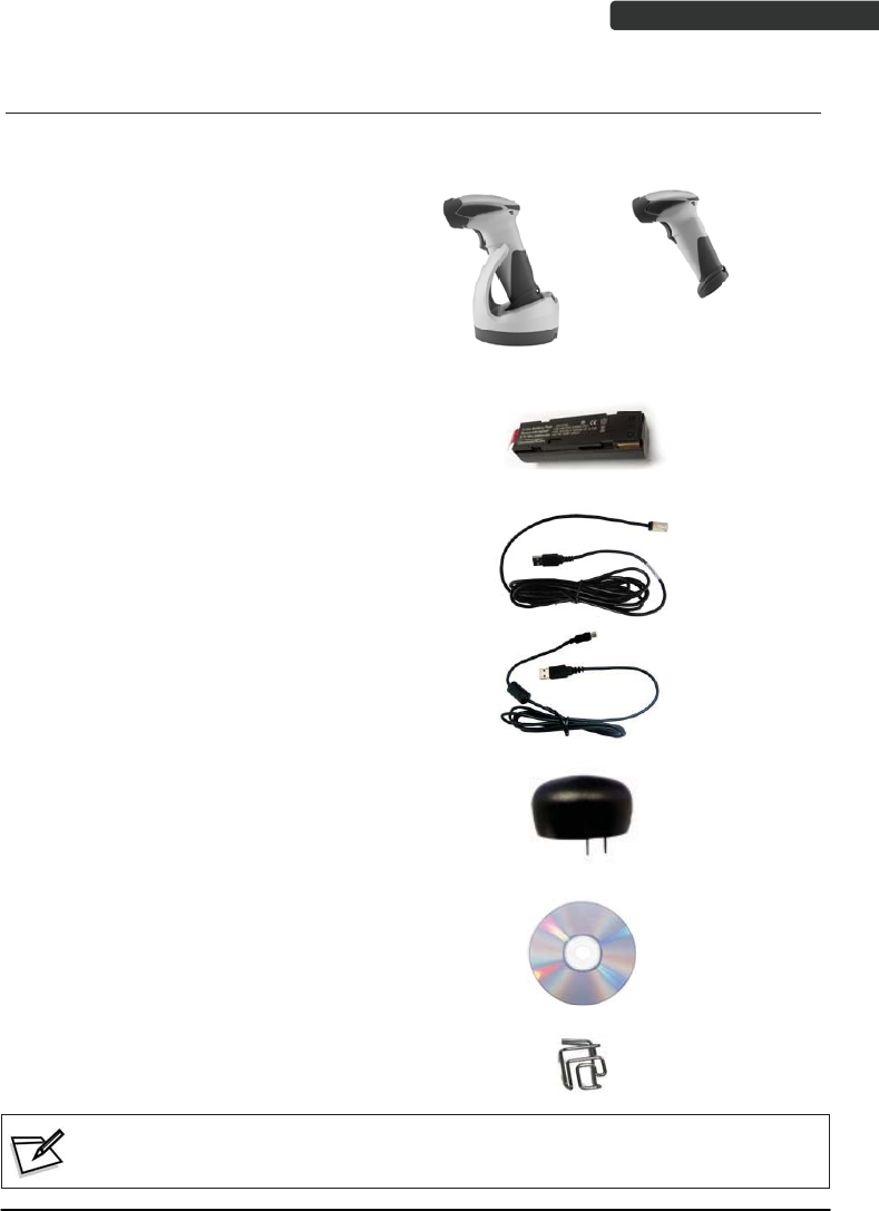
The scanner package contains:
Wireless scanner with battery /
Scanner cradle (optional)
(with cradle)
(without cradle)
Li-ion battery pack
Communication cable for cradle
(optional)
Mini USB B to mini USB A cable
5V USB Power adapter
CD-ROM or handbook
(Containing manual and programming guide)
Cable clip
If any contents are damaged or missing, please contact your dealer immediately.
USER’S MANUAL
Wireless Handheld Gun Type Scanner
4
Battery Installation
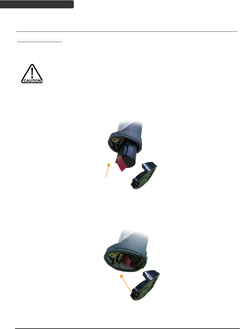
Installing Batteries
The rechargeable batteries are packed individually for shipping safety.
Please follow the steps below to install the batteries.
Always use the rechargeable batteries provided by the manufacturer to
avoid any non-compatible danger or void the warranty.
1. Unscrew the cap from the battery compartment at the bottom of the scanner and
insert the battery.
2. Make sure the red tag on the battery is tugged in and not blocking the cable
connector and close the cap.
3. Tighten the screw on the cap to secure the battery.
USER’S MANUAL
Wireless Handheld Gun Type Scanner 5
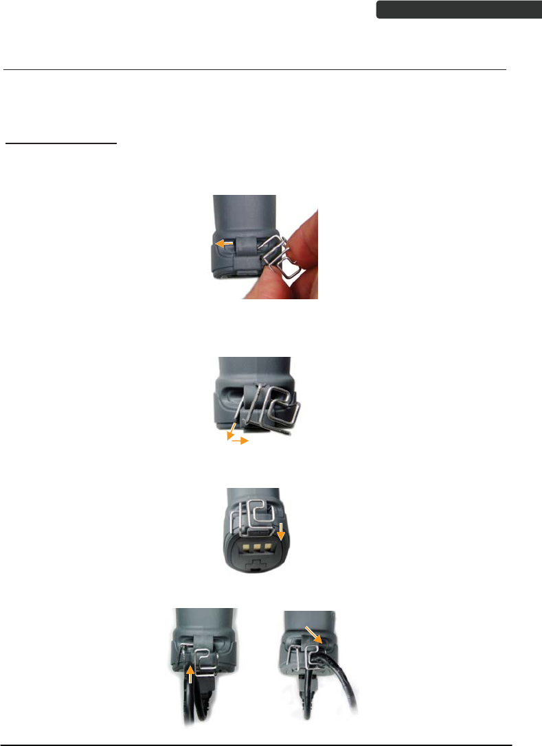
Installing Cable Clip
Cable clip is used to hold the mini USB cable in USB Online Mode. With the cable clip, you
can easily transform your wireless scanner into a wired one.
Attaching Cable Clip
1. Insert the cable clip to the strap hole as shown.
2. Gently turn the cable clip counter-clockwise and push the cable clip all the way
through the strap hole.
3. Attach the bottom part of the cable clip to the scanner handle.
4. Insert the USB cable as illustrated below.
USER’S MANUAL
Wireless Handheld Gun Type Scanner
6
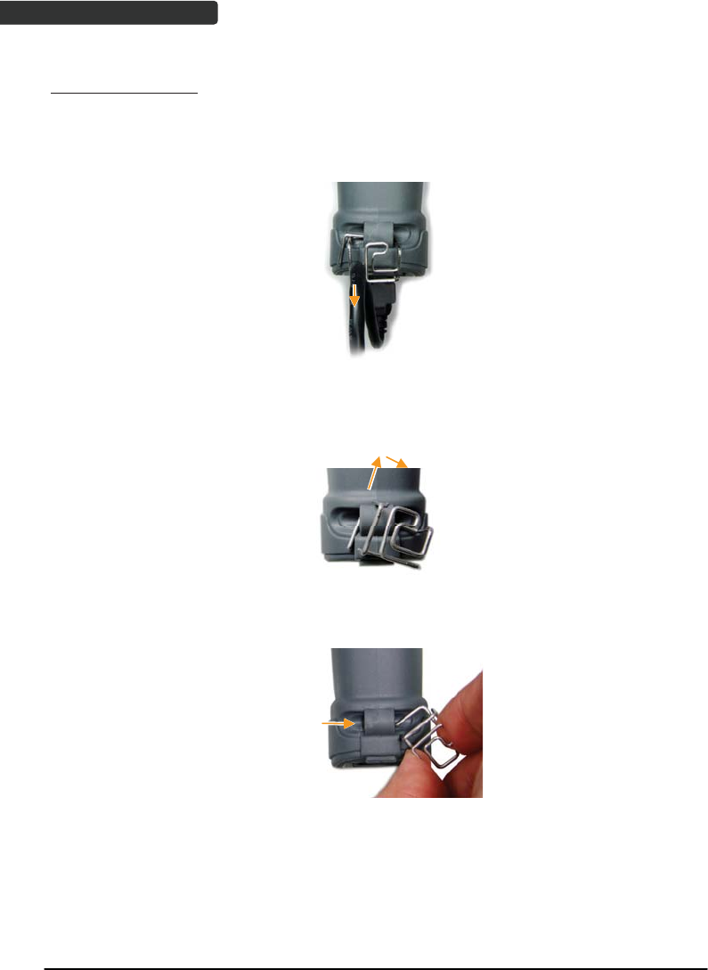
Removing Cable Clip
1. Detach the cable from the clip and detach the bottom part of the cable clip from
the scanner handle.
2. Unhook the left part of the cable clip from the strap hole then turn it clockwise.
While in turning motion, push the cable clip all the way through.
3. Remove the cable clip from the strap hole.
USER’S MANUAL
Wireless Handheld Gun Type Scanner 7
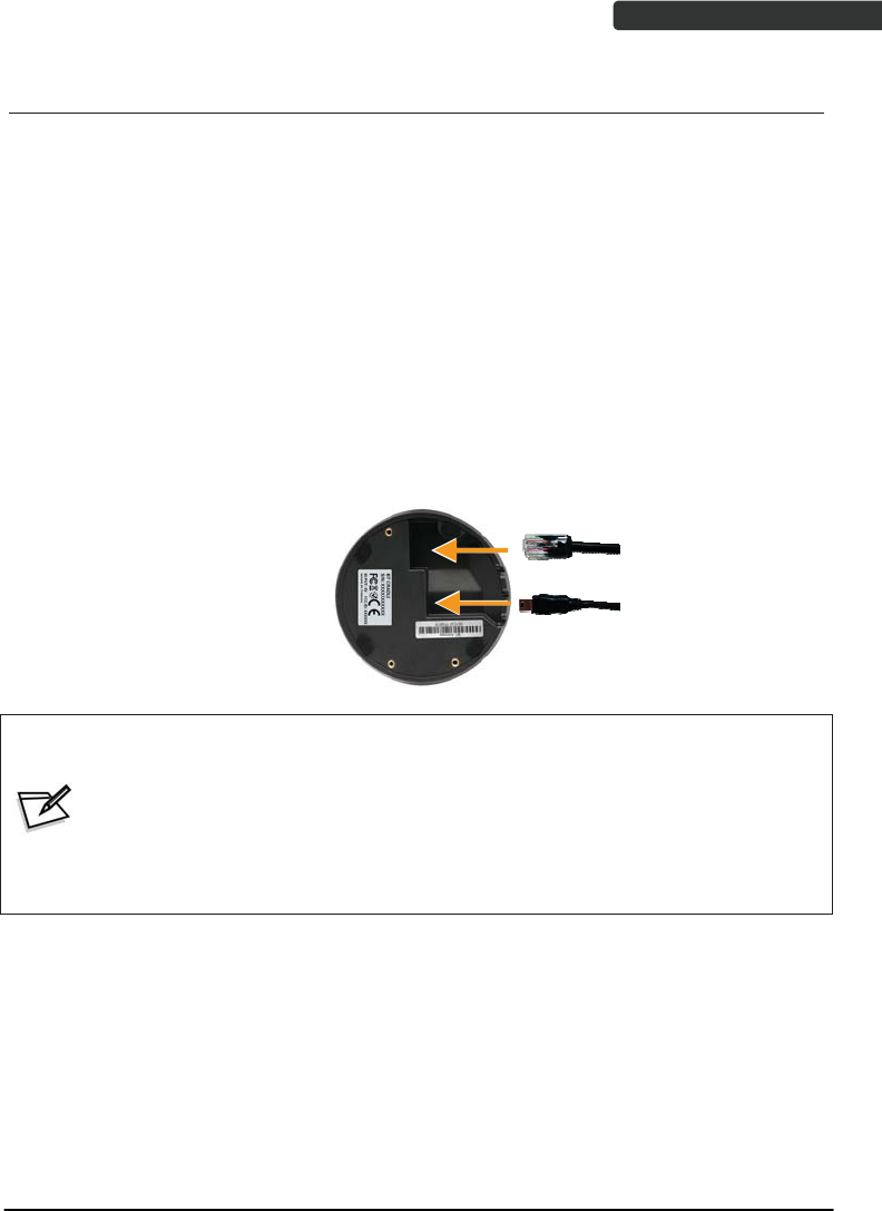
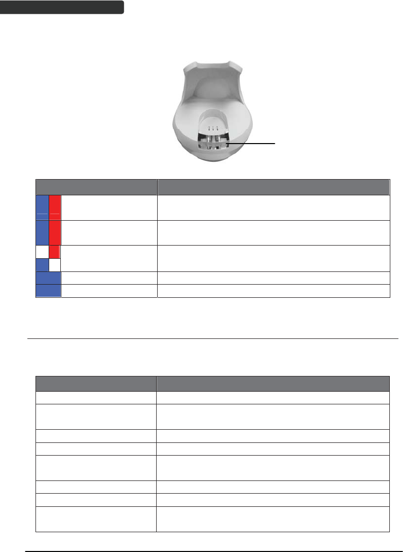
Connecting the Cradle
The cradle host features wireless technology and is designed to support radio
communication to the scanner. It can be used for both battery charging and radio
communication.
1. Take the desirable interface cable and insert the RJ-45 connector on the
bottom of the cradle. You will hear a clear and short “click” sound; then
connect the other end to the host.
2. Connect the included USB cable to mini USB port at the bottom of the cradle
and connect other end to USB power adaptor.
3. Connect the USB power adaptor into AC outlet. The LED indicator on the
cradle should flash blue until it made connection with the scanner.
Communication
cable
Mini USB B to
USB power
adaptor only
z When using Keyboard wedge and USB interface for cradle
communication, it is not necessary to have an external power adapter if
host has sufficient power. But these interfaces need external power
adapter when charging batteries.
z The mini USB port on the bottom of the cradle should only be connected
using the USB power adaptor. Please do not connect the USB cable to a
PC host for charging when using the cradle.
USER’S MANUAL
Wireless Handheld Gun Type Scanner
8
Charging the Battery
The scanner offers two different ways to charge the battery: USB Cable or Cradle.
To charge the battery using the cradle:
1. Connect the cradle. Please see Connecting the Cradle section for more details.
2. Place the scanner on the cradle. You will hear a short beep sound from the
scanner indicating scanner is in contact with the cradle.
3. The battery begins charging when the scanner LED indicator starts flashing
green. LED turns steady green when charging is complete.
Approx. charging time: 4.5 hours
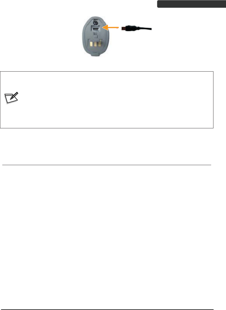
To charge the battery using the USB cable:
There are two method to charge scanner via USB cable.
z Host USB Power
z Power adaptor
1. Connect the mini USB connector directly to the scanner.
2. Connect the other end of the USB connector to the host to begin charging.
You can also connect the USB cable to an outlet using the power adapter to
charge the battery.
3. The battery begins charging when the scanner LED indicator starts flashing
green. LED turns steady green when charging is complete.
USER’S MANUAL
Wireless Handheld Gun Type Scanner 9
Approx. charging time: 5~6 hours
z The scanner will power on automatically when charging.
z Batteries shipped may not be full charged and should be fully
charged for maximum charge capacity.
z Recommended charging environment is temperature in 0̓C~35̓C (32̓ʳʳʳ
F~95̓F).
Power on the Scanner
1. Ensure the battery is fully charged. Please refer to the previous section to
charge the battery.
2. Press and hold the trigger for 1 second until a long beep sound is heard to
turn on the scanner.
USER’S MANUAL
Wireless Handheld Gun Type Scanner
10
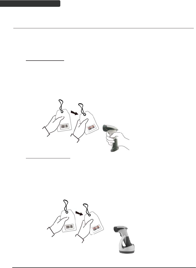
How to Scan
There are two ways to scan with this device.
z Handheld scanning
z Presentation scanning
Handheld scanning
1. Power on the scanner.
2. Press the trigger and aim at the barcode as illustrated.
3. When decoding is successful, the scanner beeps and the LED indicates blue.
Presentation Scanning
1. Put the scanner into the cradle for presentation scanning.
2. Move the barcode label approach the scanner scanning zone.
3. When decoding is successful, the scanner beeps and the LED indicates blue.
USER’S MANUAL
Wireless Handheld Gun Type Scanner 11
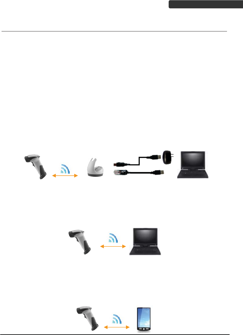
Radio Communication Host Type
This scanner support three radio communication types:
z Cradle Host mode
z SPP master/slave mode
z HID mode
Cradle Host Mode
The scanner communicates with the host through the cradle and the cradle
communicates directly to the host via host interface cable connection.
Typically, scanner and cradle in the same delivery box are paired in factory. As soon as
both are powered on, they should find and connect to each other immediately.
However, under special circumstance that the scanner and the cradle are not paired with
the cradle, please See Cradle Host Pairing for detail operation information.
SPP Mater/SPP Slave Mode
The scanner communicates with the host through wireless connection.
Please see Wireless Mode for detail operation information.
HID Mode
The scanner communicates with the smart phone through wireless HID connection.
Please see BT HID mode for detail operation information
USER’S MANUAL
Wireless Handheld Gun Type Scanner
12
Paging the Scanner
1. Ensure the cradle is properly connected to the host and LED indicator is
showing steady blue.
2. Press the function trigger on the cradle. You should hear the scanner make 3
beep sounds and blue LED flash 3 times if it is in range.
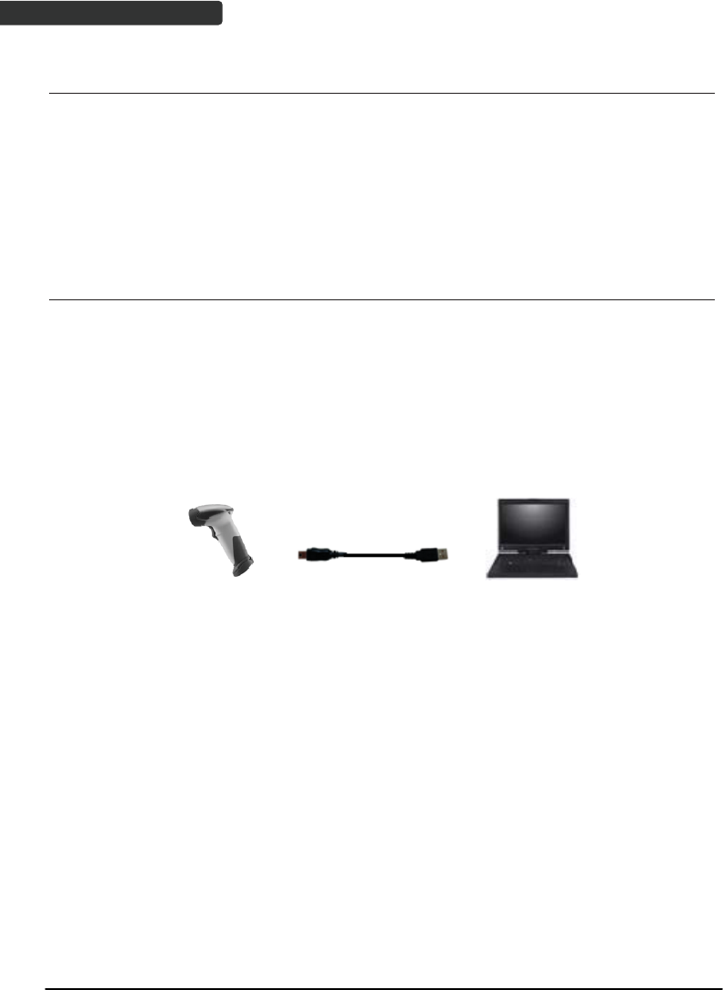
Scanner USB online to Host
The scanner provides other ways for you to connect to the host. When the
radio communication is not available, the scanner can be connected to transmit data via
USB Online mode. Please see USB Online Mode for detail operation information.
USB Online Mode
The scanner connects directly to a USB host to recharge and transmit data.
USER’S MANUAL
Wireless Handheld Gun Type Scanner 13
Visible Indicators
Scanner
There are 2 groups of LED indicators on top of the scanner. These indicate the
operational status of the scanner.
LED Status Indication
Group_ 2 Group_1
Blue Flashing Waiting for radio connection (flash time
0.5s : 0.5s).
Blue fast Flashing Radio connecting.
Blue Slow Flashing Device connected (flash time 0.03s : 3s).
1 Blue Flashing A barcode was decoded successfully
Blue Fast Flashing Data transmission
Green Flashing Charging mode
Steady Green Battery fully charged
Steady Red Programming mode
Red flashing slow
(with continuous
beep sound)
Low battery warning
Red flash twice
(with 2 beep sound)
Very low battery warning
Grou
p
2
Grou
p
1
USER’S MANUAL
Wireless Handheld Gun Type Scanner
14
Cradle
Cradle LED
LED Status Indication
Red steady and blue
continuous flashing
Cradle is radio disconnected and power from DC
adaptor is lost.
Steady red and blue Cradle is radio connected. But lost DC power from the
adaptor.
Red and blue
interchange USB Interface communication failed.
Steady blue Cradle is radio connected.
Blue flashing Cradle is radio disconnected.
Sound Indicators
When the scanner is in operation, it provides audible feedback. The beeps indicate the
status of the scanner.
Beep Indication
A long beep Power on scanner.
One beep A barcode has been successfully decoded and data is
either transfer to the host or saved in the memory.
1 high - low - high beeps Scan cradle pair barcode.
Four short medium beeps Data communication failed or out of range.
Intermission medium-low
beeps
Low battery warning.
1 short medium – low beeps Scanner is power down.
1 long high – medium beeps Enter programming mode.
1 long medium - medium
beeps
Exit Programming mode.
USER’S MANUAL
Wireless Handheld Gun Type Scanner 15
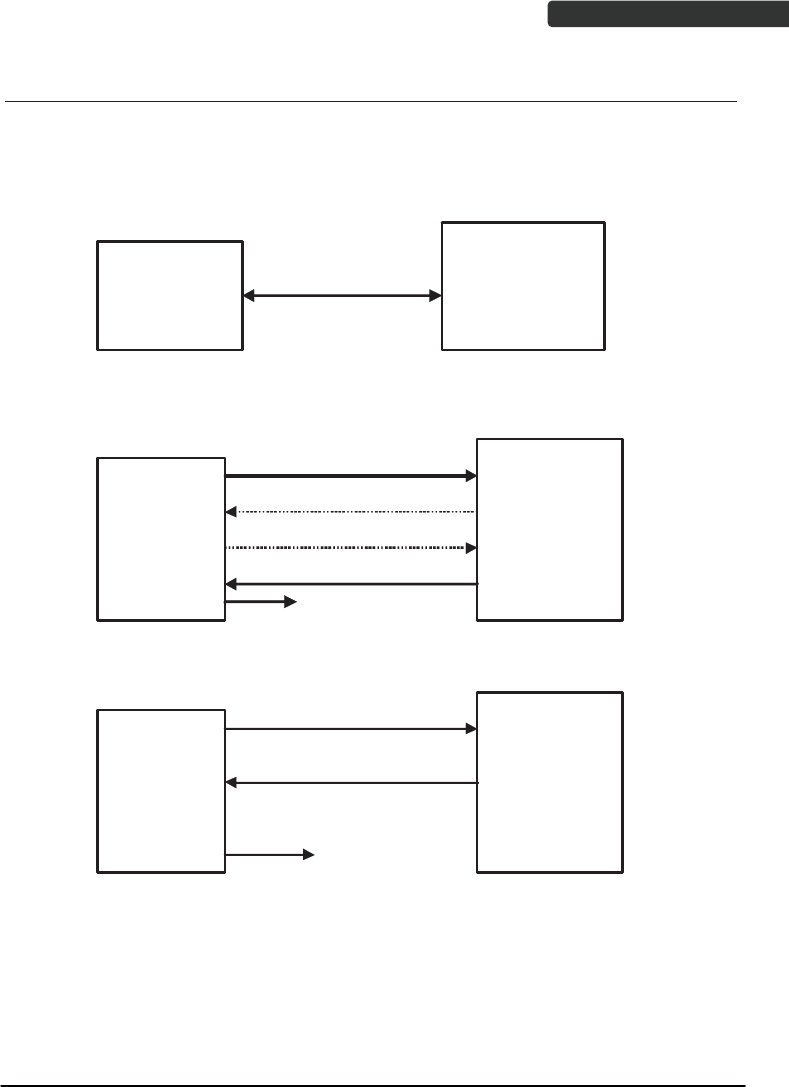
ACK/NAK Protocol or Frame Packing
When scanner is in SPP Master/Slave mode, and add in the data protocol or packing
could confirm the data reliability. Refer to below for different setting options:
a) No ACK/NAK protocol:
b) ACK/NAK only
c) Frame packing:
BT Scanner
Remote BT
device
BT scanner
Remote BT
device
data
data
NAK
Resend
ACK
Get a good beep
BT scanner
Remote BT
device
Data format of
Acknowledge
Get a good beep

Wireless Handheld Gun Type Scanner
16
USER’S MANUAL
Scanner to Remote Application
Data Format of Packet
To send a data (barcode) to the remote application, the BT scanner has to encapsulate it:
EAH
(Header)
Size of
payload
FEH
(Format
Byte)
Data
ID Data Barcode
Type
AEH
(End of
Byte)
Reserved
Byte
1 byte 1 byte 1 byte 1 byte Varies 1 byte 1 byte 1 byte
Title Definition
Header Character (EAH) The character ID at the head of every data. It has to
start with EAH.
Size of Payload The encapsulated data length excluding header
character.
Format Byte (FEH) Differentiate data format; barcode data is always FEH.
Data ID The number of each data. If receive the same ID more
than once, only the first one is valid, delete the rest.
Barcode Type (1 byte) Please refer to the Barcode Type Table.
Data Decoded barcode data.
End of Byte (AEH) Record data ends.
Reserved Byte Reserved for future use.
Example:
If Code39 barcode data is "ABCD", than sender sends out:
EAH + 0AH + FEH + ID + "ABCD "+ 11H+AEH + Reserved Byte
0AH = 1+1+1+4+1+1+1
Acknowledge packet
55H (Header ) Data ID 55H (end of byte)
1 byte 1 byte 1 byte
Example:
If scanner sends out:
EAH , 0AH , FEH , 01H , "ABCD ", 011H, AEH , EEH
Remote acknowledges: 55H +01H + 55H

Wireless Handheld Gun Type Scanner 17
USER’S MANUAL
Barcode Type Table
Code Value
Code39 0x11
Codabar 0x01
Code128 0x03
Interleaved 2/5 0x02
Code93 0x06
UPC-E 0x14
UPC-A 0x24
EAN-8 0x34
EAN-13 0x44
Chinese Post Code 0x05
MSI 0x07
Wireless Handheld Gun Type Scanner
18
USER’S MANUAL
Pin-out Configuration
Scanner mini USB Pin-Out Configuration
PIN 1. +5V
PIN 2. USB_D-
PIN 3. USB_D+
PIN 4. NC
PIN 5. GND
Cradle Phone Jack Pin-Out Configuration
RJ 1. RTS_EIA RJ 6. RX_ EIA
RJ 2. KB Data / USB_D+ RJ 7. KB Clock
RJ 3. PC Clock / USB_D- RJ 8. +5V
RJ 4. GND RJ 9. PC Data
RJ 5. CTS_ EIA RJ10. TX_ EIA
Cradle Mini USB Pin-Out Configuration
PIN 1. DC+5V
PIN 2. NC
PIN 3. NC
PIN 4. NC
PIN 5. GND
USER’S MANUAL
Wireless Handheld Gun Type Scanner 19
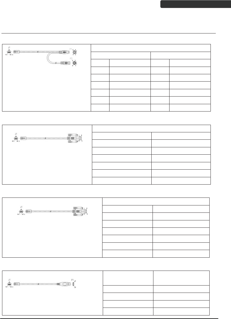
Cable Pin-out
1. Keyboard Wedge Cable (for PS/2)
PIN-OUT CONFIGURATION
MINI DIN (M) MINI DIN(F)
DIN FUNCTION DIN FUNCTION
1. PC Data 1. KB Data
2. N.C. 2. N.C.
3. GND 3. GND
4. +5V 4. +5V
5. PC Clock 5. KB Clock
6. N.C. 6. N.C.
2. RS-232 Cable (DTE pin out)
PIN-OUT CONFIGURATION
DB-9 (F) FUNCTION
2 TX
3 RX
7 CTS
8 RTS
5 GND
9 +5V
3. RS-232 Cable (DCE pin out)
PIN-OUT CONFIGURATION
DB-9 (F) FUNCTION
2 RX
3 TX
7 CTS
8 RTS
5 GND
9 +5V
4. USB / Virtual COM USB / OPOS USB Interface with Detachable Cable Type A
USB TYPE A
CONNECTOR FUNCTION
1. VCC
2. D-
3. D+
4. VSS
USER’S MANUAL
Wireless Handheld Gun Type Scanner
20
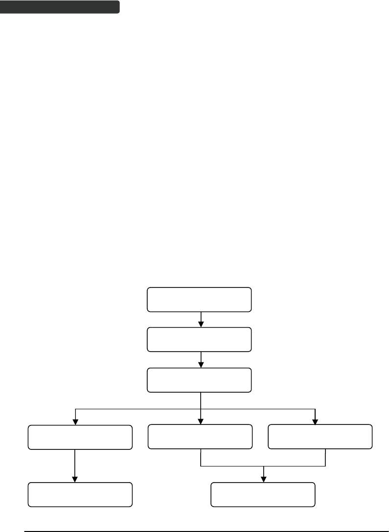
Programming Guide
Program Procedure Using Barcode Manual
1. Power up the scanner.
2. Scan the Start of Configuration barcode.
3. Scan the barcode for the desired feature. Multiple features can be
enabled/disabled before scanning the End of Configuration barcode.
4. Scan the End of Configuration barcode and save the new configuration.
5. To give up a configuration change, power off the scanner before scanning the
End of Configuration barcode or scan the Abort barcode.
6. For some parameter setting, such as barcode length and identifier code, it is
required to scan the Set barcode to save the configuration.
Scan barcode of the
desired feature
Discard the configuration
Finish the configuration
Power off the scannerScan the “Abort”barcode Scan the “End of
Configuration” barcode
Scan the “Start of
Configuration” barcode
Power up the scanner

Wireless Handheld Gun Type Scanner 21
USER’S MANUAL
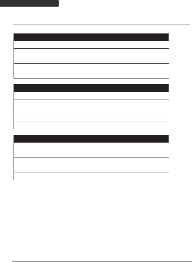
Default Parameters
The factory default setting table gives the default settings of all the programmable
parameters. The default settings will be restored whenever the "Reset" programming
label is scanned and the scanner is in programming mode. Default values are highlighted
in grey background in the settings.
Factory Default Setting
Parameter Default
Radio communication
Wireless host Cradle Host
Pairing mode Unlocked
Data transmit Normal
Radio protocol timeout 5 seconds
Power off timeout 20 minutes
Encryption Enable
Cradle Host
RS-232 communication
Baud rate 9600
Parity none
Data bits 8
Stop bit 1
RTS/CTS off
Terminator <CR><LF>
Keyboard Wedge Communication
Terminator PC/AT
Keyboard US keyboard
Terminator Enter(Alpha numeric)
USB Communication
Terminator Enter
Code mode Scan code
Keyboard US keyboard
Wand Emulation
Wand emulation speed Normal
Data output Black=high
Pair contact on cradle Enable
Scanner
Decoder Selection Default

Wireless Handheld Gun Type Scanner
22
USER’S MANUAL
EAN/UPC Enable
CODE 39 Enable
Code 32 Disable
CODABAR Enable
ITF 2 OF 5 Enable
MSI Disable
Chinese post code Disable
Code 93 Enable
Code 128 Enable
EAN-128 Disable
Telepen Disable
Code 11 Disable
Standard 2 of 5 Disable
Industrial 2 of 5 Disable
GS1 DataBar Disable
Beeper Sound Default
Frequency Medium
Duration Medium
Operating Parameter Default
Scan mode Trigger mode
Stand mode Enable
Header and trailer None
Inter-message delay None
Inter-character delay None
Code Identifiers Default
Identifier code as ZEBEX
standard
Disable
Identifier code as AIM
standard
Disable
Code 39 identifier code M
ITF 2 of 5 identifier code I
Chinese post code identifier
code
H
UPC-A identifier code A
UPC-E identifier code E
EAN-13 identifier code F
EAN-8 identifier code FF
Codabar identifier code N
Code 128 identifier code K
Code 93 identifier code L

Wireless Handheld Gun Type Scanner 23
USER’S MANUAL
MSI identifier code P
Code 11 identifier code O
Standard 2 of 5 identifier code S
Industrial 2 of 5 identifier
code
D
GS1 DataBar identifier code RS
GS1 DataBar Limited identifier
code
RL
GS1 DataBar Expanded
identifier code
RX
Default Data Transmit Format
Code Message format
EAN-13 D1 D2 D3 D4 D5 D6 D7 D8 D9 D10 D11 D12 D13
EAN-8 D1 D2 D3 D4 D5 D6 D7 D8
UPCA D1 D2 D3 D4 D5 D6 D7 D8 D9 D10 D11 D12
UPCE D1 D2 D3 D4 D5 D6 D7 D8
CODE128 D1-Dx (default 3~62)
EAN128 C1 D1-Dx (default 3~62)
CODE39 D1-Dx (default 3~62)
CODABAR D1-Dx (default 6~32)
INTERLEAVED 2/5 D1-Dx (default 6~32)
CHINESE POST CODE D1-Dx (default 8~32)
CODE93 D1-Dx (default 3~32)
MSI D1-Dx (default 6~32)
USER’S MANUAL
Wireless Handheld Gun Type Scanner
24
Connecting to a Host
The scanner provides several data transmit methods to communicate with the host. User
may select the method according to their preferences. Read this section to learn the
setups for connecting to different hosts.
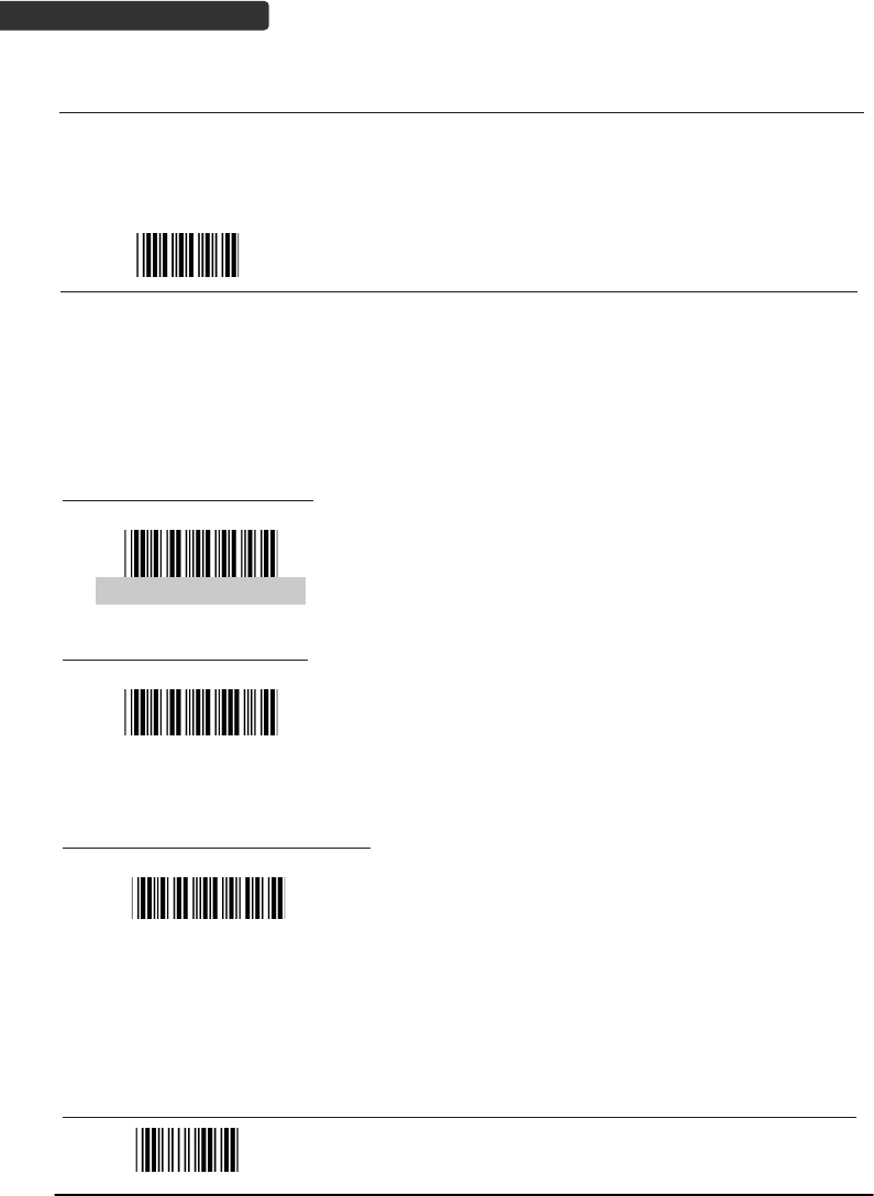
Start Of Configuration
USB Online Mode
The scanner connects directly to a USB host to recharge and transmit data. You may
enable or disable the functions using the following settings.
Disable USB communication
USB online scan disable
Disable USB communication.
Enable USB communication
USB online scan enable
Wireless connection as the primary communication
option to the host. USB connection is only used when
wireless is disconnected.
Set USB as the primary connection
USB online scan, Ignore
radio communication
USB connection as the primary communication option
to the host when it is available. Wireless mode is set
as the secondary option.
End Of Configuration

USER’S MANUAL
Wireless Handheld Gun Type Scanner 25
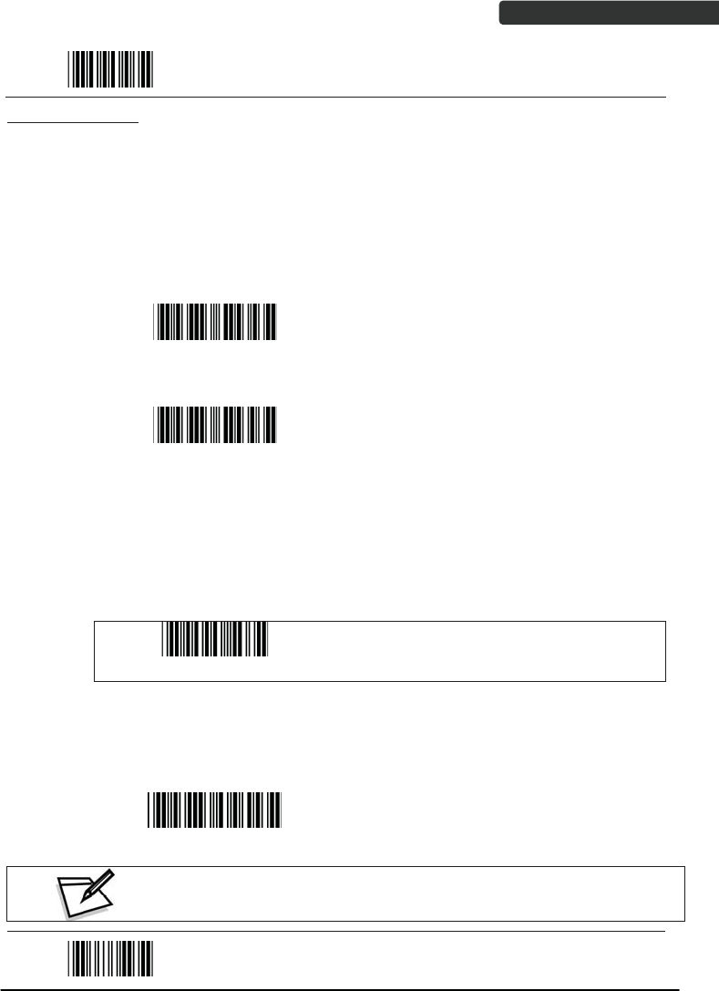
Start Of Configuration
Cradle Host Mode
The scanner communicates with the host through the cradle. Typically, scanner and
cradle in the same delivery box are paired and corresponded to host interface in factory.
To check if the scanner is paired to the cradle, check the scanner LED group1 for slow
blue flash and check the top cradle LED for steady blue light. If LED group1 of scanner and
top LED of cradle are both flashing blue, follow the steps below to radio connect the
scanner and cradle.
Cradle Host Pairing
1. See Connecting the Cradle to connect the cradle and the computer. Please
make sure the cradle LED is flashing blue indicating it’s not linked to any
scanner. If the LED shows steady blue, the cradle is already paired to another
scanner so you must unpair the scanner before continuing.
2. Power on the scanner and enable cradle host mode if necessary.
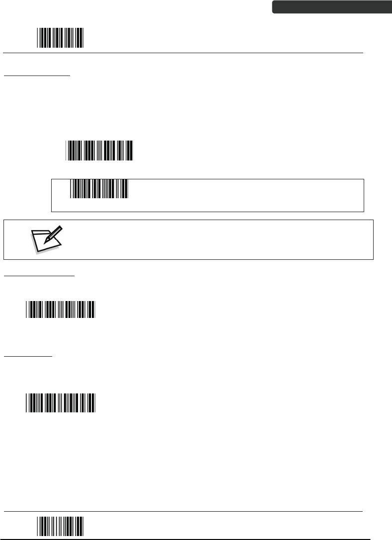
Cradle Host mode enable
Enable cradle mode with this set.
3. Use the scanner to scan the pairing barcode at the bottom of the cradle to
begin pairing. 3 short beeps will be heard.
4. The LED indicator on the scanner will flash blue rapidly indicating search
mode in process. The LED on the cradle becomes steady blue when the
pairing is successful.
5. Scan the corresponding host interface the cradle is using to begin using the
scanner.
Return to USB defaultʳ
Return to cradle USB communication.ʳ
(Communication cradle link required)
Return to wand
emulation default
Return to cradle wand emulation.
(Communication cradle link required)
Return to RS232 default
Return to RS232 cradle communication.
(Communication cradle link required)
IBM PC/AT/PS/2 Keyboard
emulation
Cradle IBM PC/AT/PS/2 Keyboard emulation.
(Communication cradle link required)
End Of Configuration

USER’S MANUAL
Wireless Handheld Gun Type Scanner
26
Start Of Configuration
Wireless Mode
The scanner connects to the host via wireless connection. You may select SPP Master or
SPP Slave for PC connection or select HID mode and Smart phone mode for smart phone
connection.
SPP Slave Mode
In this mode, the scanner connects to the host /PC via wireless connection and performs
like there’s a serial connection. In SPP Slave mode, the scanner is discoverable from a
remote device and it can request the scanner for connection. There are several ways to
connect the wireless scanner to your PC. If you have your own applications please check
their User’s Manuals for pairing instructions.
To connect a wireless device to Window based system for the first time:
1. Turn on the host computer and activate its wireless connection.
2. Select “Add wireless device”. Or open the dialog BT devices and click “Add”.
3. Power on the scanner and program it with “SPP Slave mode” label.
Scanner SPP Slave enable
Enable wireless SPP Slave mode.
4. On Devices tab, click Add. This will open the Add wireless Device Wizard.
5. Select the "My device is set up and ready to be found" checkbox, and then
click Next.
6. The scanner should be on the list of discoverable devices. The default name
of the scanner is “ZBBT”. Select “ZBBT” and click “Next”.
7. Select “Let me choose my own passkey” and enter the pin code. The default
pin code is “12345678.
8. Click “Next” to connect the scanner to the host. A short beep should be
heard upon connection.
End Of Configuration
USER’S MANUAL
Wireless Handheld Gun Type Scanner 27
Start Of Configuration
SPP Master Mode
In this mode, the scanner connects to the host /PC via wireless connection and performs
like there’s a serial connection. In master mode, the scanner initiates the connection to
the remote deviceˁ
1. Power on of the remote device and have its address ready in hand and make
it discoverable.
2. Program the scanner with the “SPP Master enable” barcode.
Scanner SPP Master enable
Enable SPP Master mode.
3. Scan “Set wireless address” to set the address.
Set wireless address
(SPP Master only)
Set wireless address for SPP Master
connection.
4. Use the ASCII table in Programming Guide to input the 12 digit wireless
address. For example: if the address is “011B1345600”, scan “0”, “0”, “1”, “1”,
“B”, “1”, “3”, “4”, “5”, “6”, “0”, “0” from ASCII barcode labels.
5. Scan “Confirm Setting” to store the address.
Confirm Setting (for address and pin code
setting required)
6. Setup and input the pin code if necessary. Please see Setting Pin Code section
for more details.
7. Scan “Required Pair with slave (SPP Master)” to begin pairing.
Required Pair with slave (SPP Master)
In SPP Master mode, you can print out a Code39 label of the
wireless address in “BxxxxxxxxxxxxT” format and scan it with the
scanner instead of using the ASCII table.
End Of Configuration
USER’S MANUAL
Wireless Handheld Gun Type Scanner
28
Start Of Configuration
BT HID mode
In BT HID mode, the scanner connects to the host /PC via wireless connection and
performs like there’s a keyboard connection. The scanner initiates the connection to the
remote deviceˁ
1. Power on the scanner and program it with “BT HID Mode”. To connect a
smart mobile phone (for example, iPhone, Android), the Smart phone mode
must also be enabled.
BT HID mode
Enable wireless HID keyboard emulation
Smart phone mode
For smart phone mode (BT HID MODE must also be
enabled).
2. Enable wireless connection on your host and follow the instructions in your
host to set it to discover other wireless devices in its surrounding.
3. The scanner should be on the list of discoverable devices. The default name
of the scanner is “ZBBT”. You will be prompt to enter paring pin code. Select
“ZBBT” and input the pin code that appears on your mobile device to connect
scanner to the phone.
4. Scan the Enter barcode to confirm. A short beep should be heard upon
connection.
Enter
Full ASCII ---CR
Function key-----“Enetr(num.)”
End Of Configuration
USER’S MANUAL
Wireless Handheld Gun Type Scanner 29
Start Of Configuration
Setting Pin Code
1. To change the pin code, use the “Set pin code” setting. Default is “12345678”.
2. Use the ASCII table in Programming Guide to input the new code (must be at
least 4 digits and not more than 8 numeric digits).
3. Scan “Save Setting” to store the pin code.
Set pin code
Set pin code (SPP Master only)
Confirm Setting (for address and pin code setting
required)
Please check the User’s Manual from your PC for wireless address and pin code.
Deleting pin code
To delete pin code, use the “Delete pin code setting”.
Delete pin code
Delete the stored pin code.
Reset Name
To change the scanner name back to the default name “ZBBT” use the “Default device
name” setting.
Default device name
Change device name back to default “ZBBT”.
End Of Configuration
USER’S MANUAL
Wireless Handheld Gun Type Scanner
30
Start Of Configuration
Setting Name
1. To change the name displayed when the scanner is discovered, scan the
“Friendly device name set” label. Default name is “ZBBT”.
2. Use the ASCII table in Programming Guide to input the name (Max.12 digits).
3. Scan “Confirm Setting” to store the new name.
Friendly device name set
Change the display name when scanner is
discovered.
Confirm Setting (for address and pin code
setting required)
Wireless Discovery
Use the following settings to show or hide the device from wireless discovery.
Discover enable
Make scanner visible to wireless device.
Discover disable
Make scanner invisible to wireless device.
End Of Configuration

USER’S MANUAL
Wireless Handheld Gun Type Scanner 31
Start Of Configuration
Data Transnit Method
The data transfer method includes three types: Normal (default), Out-of-Range Mode,
and Batch Mode. Users may modify this setting according to their preferences.
Normal
When the scanner is within the connection range, the scanned data will be transferred to
the host computer immediately. If the scanner is out of its connecting range, the scanner
does not send or store any data.
Data transmit normal
Batch mode is disabled.
Out of Range
Scanned data are stored when scanner is out of its wireless communication range. When
scanner is back into its communication range or re-connected, the stored data are sent
when scanning next barcode label.
Out of range buffer
enable
Enable out of range mode.
End Of Configuration
USER’S MANUAL
Wireless Handheld Gun Type Scanner
32
Start Of Configuration
Batch Mode
Whether within the connection range or not, in batch mode, the scanner stores all
scanned data that will be transferred to the host computer after scanning “Send Batch
Data” label.
Number of storable bar codes = 61,365 bytes of memory / (number of characters in the
bar code +2)
Batch mode
Note: Scanner LED indicator will not flash while waiting for
connection in this mode.
Clearing Batch
Use the settings in this section to clear the stored data.
Clear batch data after
send
Saved data are cleared after they are transferred to the
host.
Clear batch data by
scanning “Delete batch
data” label
Scan this label then scan “Save Setting” to delete the
stored batch data.
Delete batch data
Same as previous setting but with alert sound.
Confirm Setting (for address and pin code setting
required)
End Of Configuration
USER’S MANUAL
Wireless Handheld Gun Type Scanner 33
Start Of Configuration
Batch Transfer
Use the settings in this section to setup batch transfer.
Send Batch Data By
Scanning Label
Scanning this label automatically exits you from the
Programming Mode. Press and hold the trigger for over
1 second to send the data.
Send Batch Data on line
USB cable contact
Data is ready to be transferred upon USB connection.
Press and hold the trigger for over 1 second to send
the data.
Send Batch data on cradle
Data is ready to be transferred upon placement on the
cradle. Press and hold the trigger for over 1 second to
send the data.(Cradle radio connected is required)
Batch Mode Sounds Settings
Use the settings in this section to setup the sound.
Out of range resend data
with beeper sound
Add beeper sound when resending data in Out of range
mode.
Out of range resend data
without beeper sound in
Out of range mode.
No beeper sound when resending data
Send Batch Data without
beep
No beep when sending data. Good-read LED will light
up until the transfer is done.
Send Batch Data with Beep
Beep sound when sending data. Good-read LED will
light up until the transfer is done.
End Of Configuration

USER’S MANUAL
Wireless Handheld Gun Type Scanner
34
System Function Settings
Default values are highlighted in grey background.
Start Of Configuration
Barcode Value Description
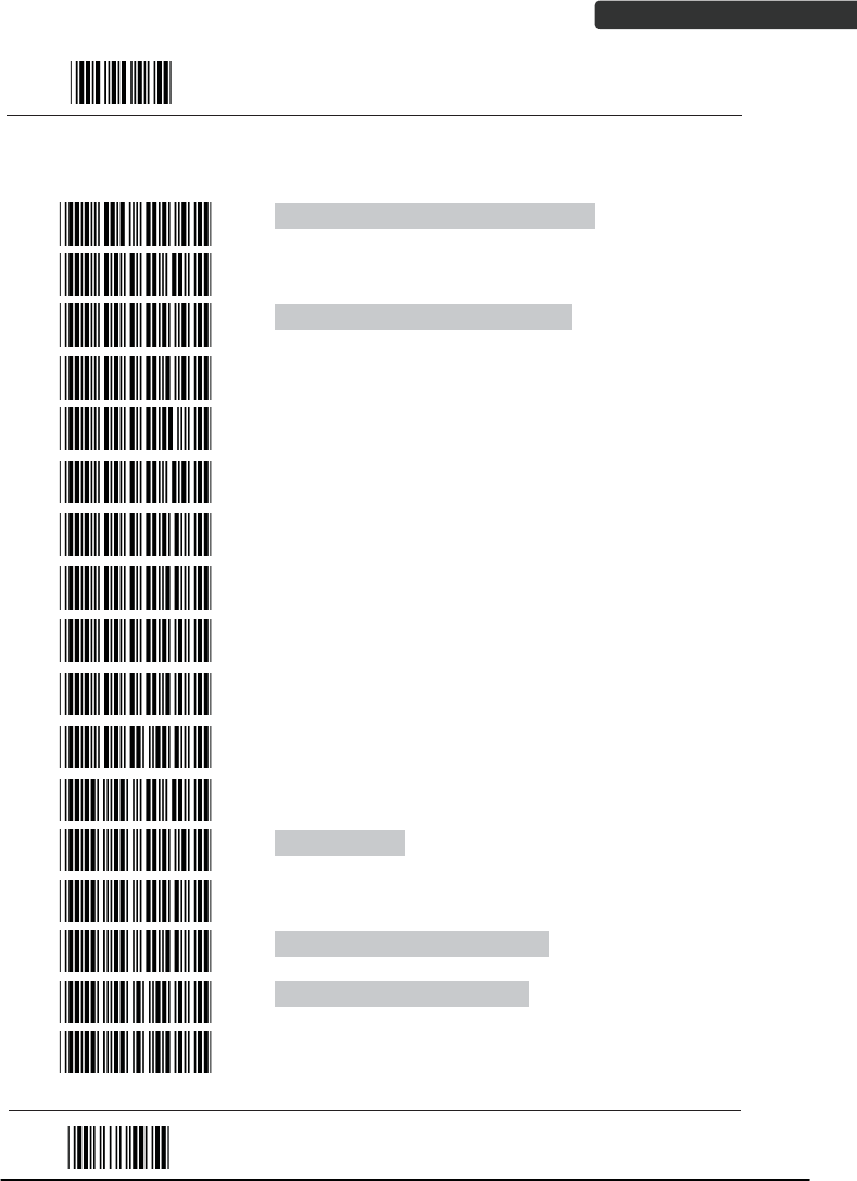
Return scanner to factory defaults
Return cradle host to factory defaults
Return to USB default
(Communication cradle link required)
Return to wand emulation default
(Communication cradle link required)
Return to RS232 default
(Communication cradle link required)
IBM PC/AT/PS/2 keyboard emulation
(Communication cradle link required)
Return as USB-virtual COM port default
Return to stand-alone keyboard default
Return as OPOS port default
End Of Configuration

USER’S MANUAL
Wireless Handheld Gun Type Scanner 35
Start Of Configuration
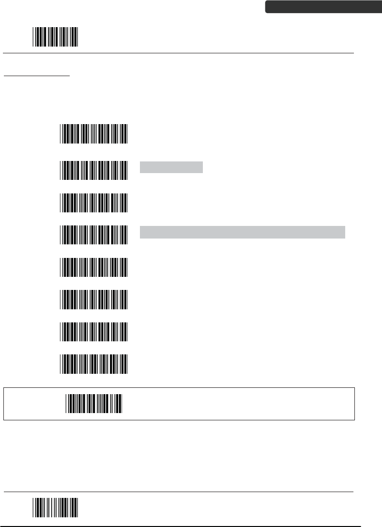
Barcode Value Description
Display firmware version
Abort
(exit programming mode without any updates)
Scan Mode
Trigger mode
The scanner becomes inactive as soon as the data is
transmitted. It must be triggered to become active again.
Auto scan mode
The scanner is still active after the data is transmitted but
the successive transmission of the same barcode is not
allowed when the trigger switch is pressed again.
Alternate mode
The scanner illumination alternates between on and off
when the trigger switch is pressed.
Presentation mode
Also called auto trigger mode. The scanner is inactive but
will automatically detect barcodes presented in the scan
zone and become active.
Idle mode enable
Idle mode disable
Disable Idle mode.
End Of Configuration
USER’S MANUAL
Wireless Handheld Gun Type Scanner
36
Start Of Configuration
Radio Communication Setting
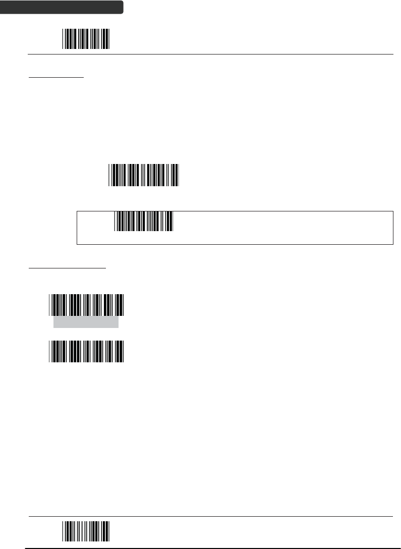
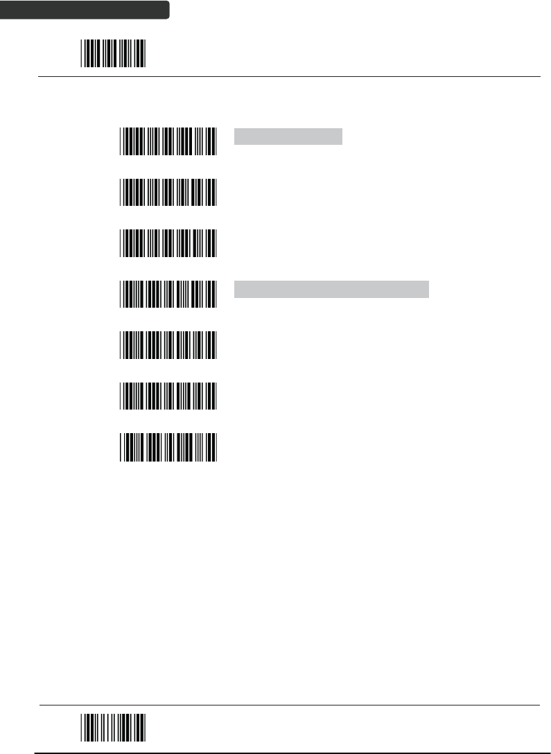
Cradle Host mode
Cradle Host mode enable
Enable cradle mode with this setup.
Unlock pairing mode
In this mode, the scanner can pair with another cradle
when disconnected.
Lock pairing mode.
In this mode, the scanner can not pair with another
cradle.
Undo pairing
Undo the pairing between the cradle and the scanner.
Scanner On Cradle sound alert enable
Enable beep sound alert when scanner is placed on
cradle.
Scanner On Cradle sound alert disable
Disable beep sound alert when scanner is placed on
cradle.
On Cradle Auto-Scan mode enable
Enable Auto-Scan when scanner is placed on cradle.
On Cradle Auto-Scan mode disable
Disable Auto-Scan when scanner is placed on cradle.
End Of Configuration

USER’S MANUAL
Wireless Handheld Gun Type Scanner 37
Start Of Configuration
USB Online mode
USB online scan disable
USB online scan enable
USB online scan, Ignore radio communication
BT HID mode
BT HID mode (Combo keyboard)
For Apple mode (Must execute BT HID mode first)
SPP Master/Slave mode
Scanner SPP Master enable
SPP Master (Connect wireless address
“BxxxxxxxxxxxxT” in CODE39 format)
Scanner SPP Slave enable
Setting wireless address (SPP Master only)
Set PIN code (SPP Master only)
End Of Configuration
USER’S MANUAL
Wireless Handheld Gun Type Scanner
38
Start Of Configuration
Default Device name
Friendly device name set
Delete pin code
Confirm Setting (for address, device name, and pin
code setting required)
Required Pair with slave (SPP Master)
Discover enable
Discover disable
Encryption enable
Encryption disable
Data communication without protocol
Data communication with ACK/NAK protocol
Data communication with Packing protocol
End Of Configuration

USER’S MANUAL
Wireless Handheld Gun Type Scanner 39
Start Of Configuration
Data Transmit Mode
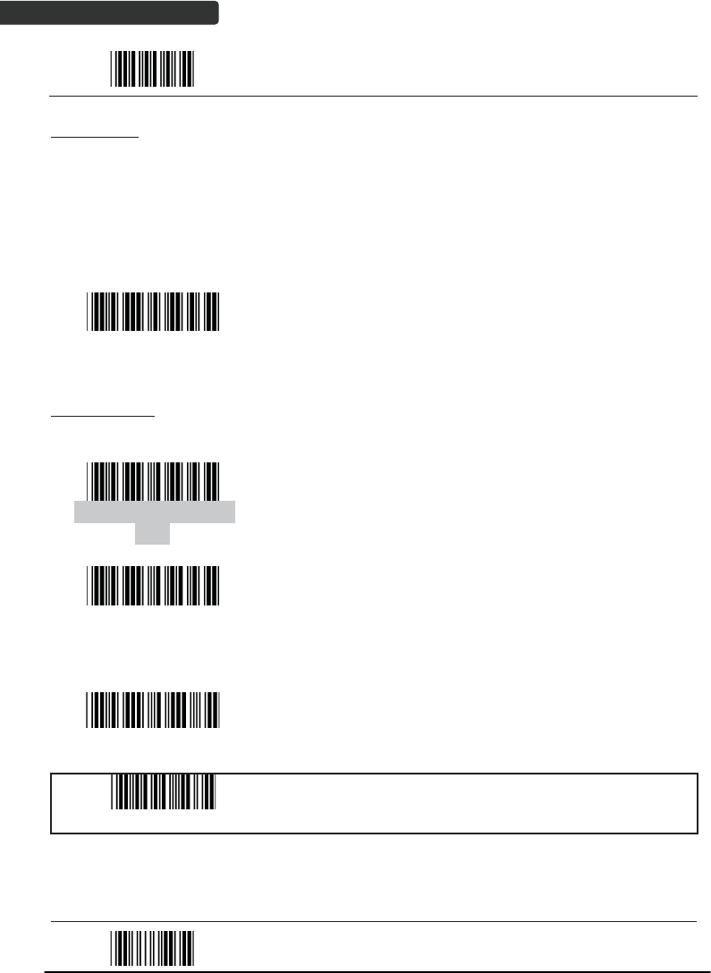
Data transmit normal
Out of range buffer enable
Batch mode
Send Batch Data By Scanning Label
Clear batch data after send
Clear batch data by scanning “Delete batch data” label
Delete batch data
Send Batch Data on line USB cable contact.
Send Batch data on cradle
Out of range resend data with beeper sound
Out of range resend data without beeper sound
Send Batch Data without Beep
Send Batch Data with Beep
End Of Configuration

USER’S MANUAL
Wireless Handheld Gun Type Scanner
40
Start Of Configuration
Radio protocol communication parameter
Radio protocol timeout= 3 sec
Radio protocol timeout= 5 sec
Radio protocol timeout =8 sec
Radio protocol timeout= 10 sec
Radio protocol timeout =13 sec
Radio protocol timeout =16 sec
Radio protocol timeout= 20 sec
End Of Configuration

USER’S MANUAL
Wireless Handheld Gun Type Scanner 41
Start Of Configuration
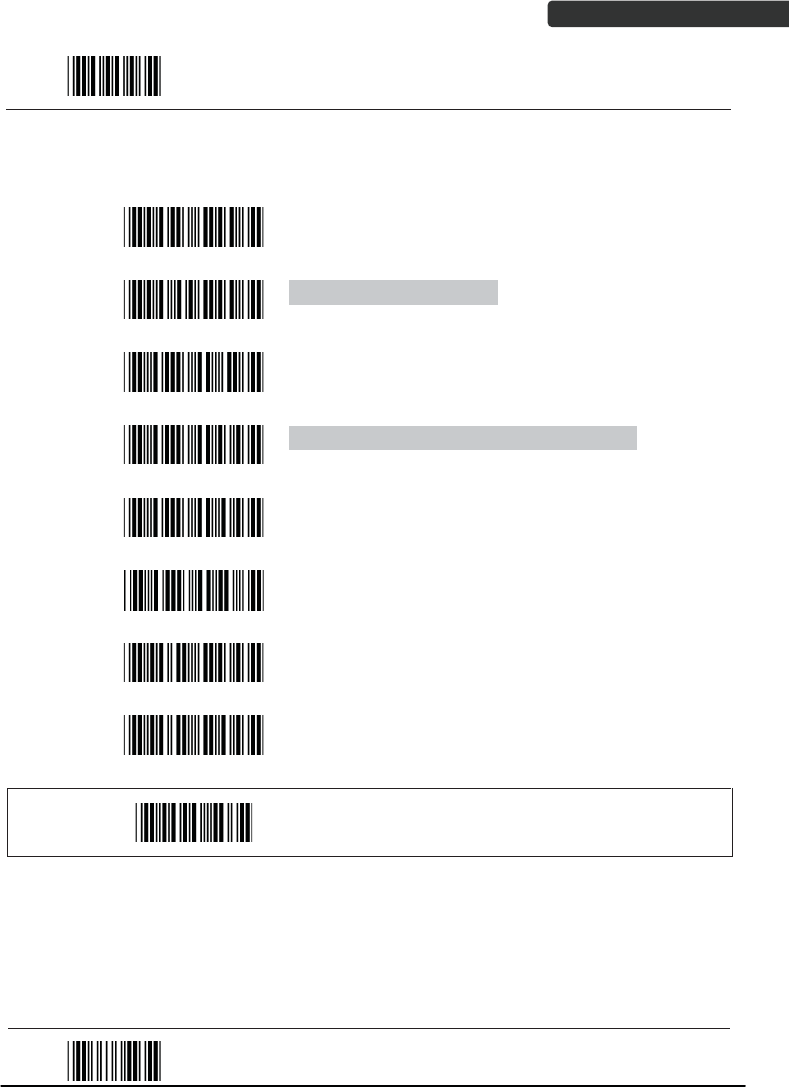
Power off timeout parameter
Power off timeout=5 min
Power off timeout=10 min
Power off timeout=20 min
Power off timeout=30 min
Power off timeout=1 hr
Power Off timeout : 2 hr
Power Off timeout : 4 hr
Power Off timeout : 6 hr
Power Off timeout : 8 hr
End Of Configuration
USER’S MANUAL
Wireless Handheld Gun Type Scanner
42
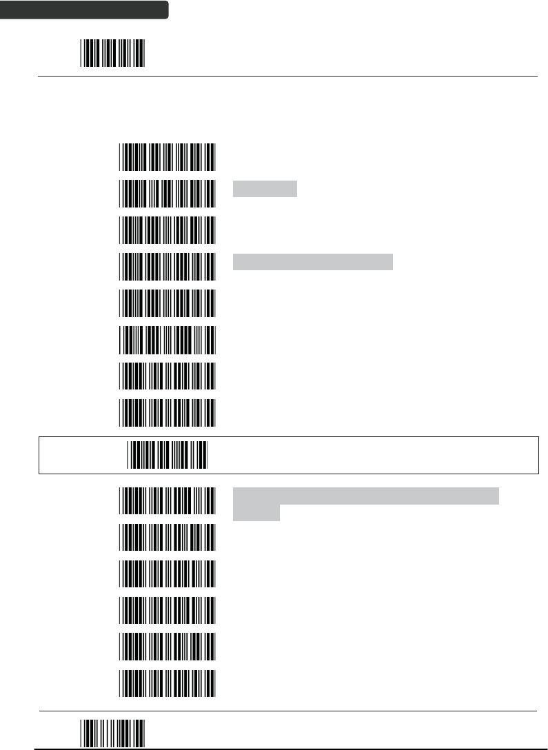
Start Of Configuration
Power Always On
Power off by scanning this label
Link beeper enable
Link beeper disable
Power-up beeper enable
Power-up beeper disable
Same Code Delay
50 msec
100 msec
200 msec
300 msec
End Of Configuration

USER’S MANUAL
Wireless Handheld Gun Type Scanner 43
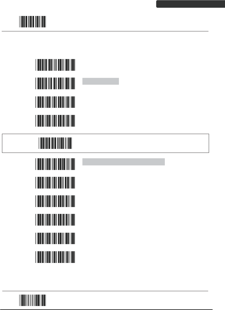
Start Of Configuration
400 msec
500 msec
600 msec
700 msec
800 msec
1000 msec
Infinite
End Of Configuration

USER’S MANUAL
Wireless Handheld Gun Type Scanner
44
Start Of Configuration
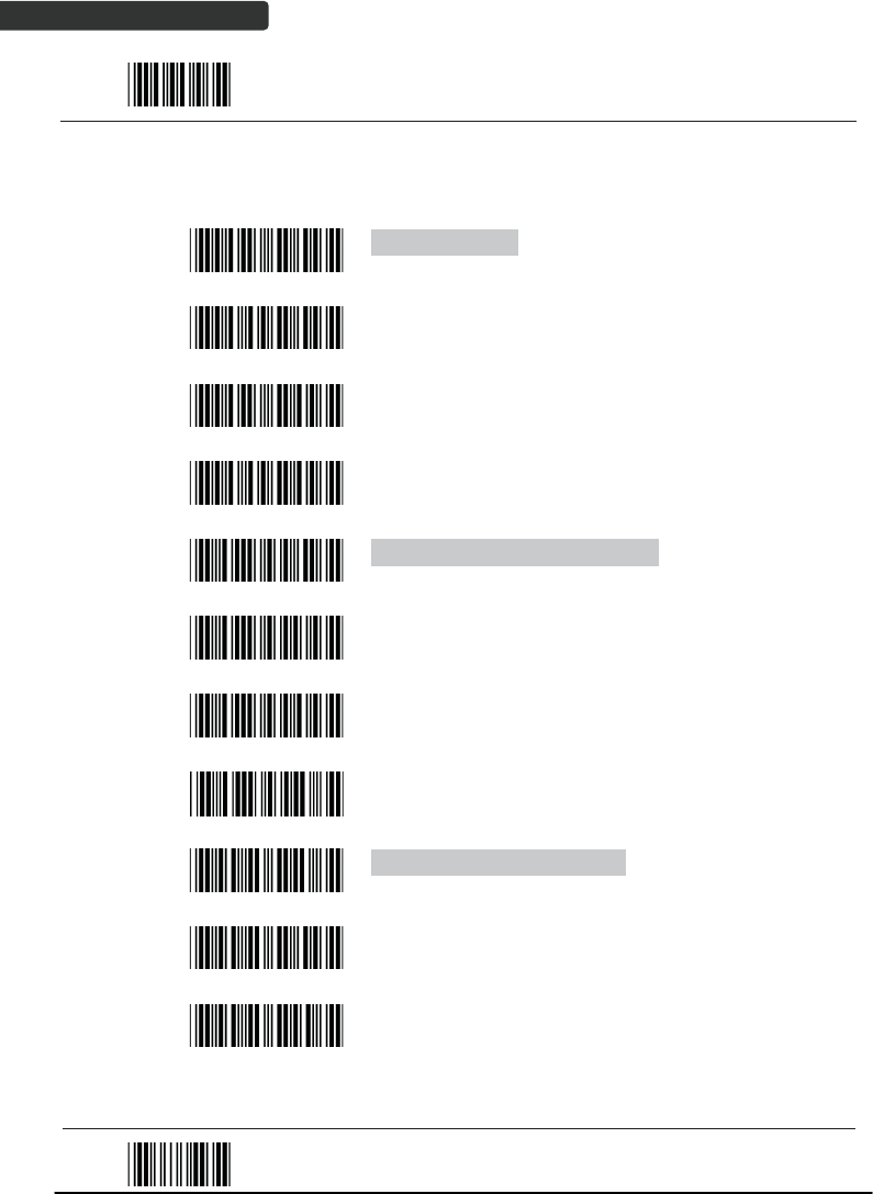
Operation Function Setting
Good Read Beeper Tone Selection
Medium beeper tone
High beeper tone
Low beeper tone
Speaker disable
End Of Configuration

USER’S MANUAL
Wireless Handheld Gun Type Scanner 45
Start Of Configuration
Beeper duration Selection
Long
Medium
Short
Ultra Short
Ultra Long
End Of Configuration

USER’S MANUAL
Wireless Handheld Gun Type Scanner
46
Start Of Configuration
Vibration Parameter
(Optional function, available only for customers of special request )
Good read vibrator enable.
Good read vibrator disable
Good read beeper and vibrator enable
Vibration duration=100msec
Vibration duration=200msec
Vibration duration=300msec
Vibration duration=400msec
Vibration duration=500msec
Vibration duration=1 second
Vibration duration=2 second
Vibration duration=3 second
Vibration duration=4 second
Vibration duration=5 second
End Of Configuration

USER’S MANUAL
Wireless Handheld Gun Type Scanner 47
Start Of Configuration
Inter Character Delay
0 ms
2 ms
5 ms
10 ms
20 ms
50 ms
Inter Message Delay
0 ms
100 ms
500 ms
1000 ms
End Of Configuration
USER’S MANUAL
Wireless Handheld Gun Type Scanner
48
Start Of Configuration
Interface Settings
1. RS-232C Interface Setting
Baud Rate
115200
19200
9600
4800
2400
1200
Parity Bit
Even parity
Odd parity
Mark parity
Space parity
None parity
Stop Bit
1 stop bit
2 stop bit
Data Bit
7 data bit
8 data bit
End Of Configuration

USER’S MANUAL
Wireless Handheld Gun Type Scanner 49
Start Of Configuration
Handshaking Protocol
None handshaking
ACK/NAK
Xon/Xoff
RTS/CTS
Enable BEEPER ON<BEL> CHARACTER
Ignore Beep on<BEL> character
ACK/NAK response time 300ms
ACK/NAK response time 2 sec
ACK/NAK response time 500 ms
ACK/NAK response time 3 sec
ACK/NAK response time 1 sec
ACK/NAK response time 5 sec
ACK/NAK response time infinity
End Of Configuration

USER’S MANUAL
Wireless Handheld Gun Type Scanner
50
Start Of Configuration
Message Terminator
RS-232 message terminator—none
RS-232 message terminator—CR/LF
RS-232 message terminator—CR
RS-232 message terminator—LF
RS-232 message terminator—H tab
RS-232 message terminator—STX/ETX
RS-232 message terminator—EOT
End Of Configuration
USER’S MANUAL
Wireless Handheld Gun Type Scanner 51
Start Of Configuration
2. Keyboard Wedge Setting
Keyboard Wedge Setting
IBM PC/AT/PS/2 Keyboard emulation
International Keyboard mode ( ALT method)
Keyboard language support---USA
Keyboard language support---UK send scan code
Keyboard language support---GERMANY
Keyboard language support---FRENCH send scan
code
Keyboard language support---SPANISH send scan
code
Keyboard language support---ITALIAN send scan
code
Keyboard language support---Switzerland send scan
code
Keyboard language support---Belgium send scan
code
Keyboard language support---Japanese
Capital lock on
Capital lock off
Function key emulation enable
Function key emulation disable
Send number as normal data
Send number as keypad data
End Of Configuration

USER’S MANUAL
Wireless Handheld Gun Type Scanner
52
Start Of Configuration
Message Terminator
Keyboard terminator---none
Keyboard terminator---Enter
Keyboard terminator---H-TAB
End Of Configuration

USER’S MANUAL
Wireless Handheld Gun Type Scanner 53
Start Of Configuration
3. USB Interface Setting
USB interface
International Keyboard mode ( ALT method)
Keyboard language support---USA
Keyboard language support---GERMANY
Keyboard language support---FRENCH send scan
code
Keyboard language support---SPANISH send scan
code
Keyboard language support---JAPANESE
Keyboard language support---ITALIAN
Message Terminator
Keyboard terminator---none
Keyboard terminator---Enter
Keyboard terminator---H-TAB
End Of Configuration

USER’S MANUAL
Wireless Handheld Gun Type Scanner
54
Start Of Configuration
4. Wand Emulation Setting
Wand emulation is not supported as standard, if needed, please contact your distributor.
(Code128, Code93 not supported)
Wand Emulation
All barcode will be decoded and transmitted in that
symbology
Enable Wand output data format as CODE39
Wand emulation data output black=high
y Scan this bar code to set quiet zones and
spaces low and bars =high.
Wand emulation data output black=low
y Scan this bar code to set quiet zones and
spaces high and bars=low
Idle = high
y Idle state refers to the TTL logic level of the
Wand Emulation signal when not in use
Idle = low
y Idle state refers to the TTL logic level of the
Wand Emulation signal when not in use
End Of Configuration

USER’S MANUAL
Wireless Handheld Gun Type Scanner 55
Start Of Configuration
Wand Emulation (Cont’d)
Wand emulation speed-----Low
y This option allows the transmission of wand
emulation at 1ms narrow element width
Wand emulation speed-----medium
y This option allows the transmission of wand
emulation at 600us narrow element width
Wand emulation speed-----high
y This option allows the transmission of wand
emulation at 300us narrow element width
Wand emulation speed-----higher
y This option allows the transmission of wand
emulation at 100 us narrow element width
End Of Configuration

USER’S MANUAL
Wireless Handheld Gun Type Scanner
56
Start Of Configuration
5. Smart Phone Software Keypad Control Setting
Smart Phone Software Keypad Control
Multi-media keyboard mode
y This option enables Multi-media keyboard
mode
Software keypad enable/disable
y This option enable or disable Software
keypad
To enable/disable Software keyboard:
1. Scan the Start Of Configuration barcode.
2. Scan the Multi-media keyboard mode barcode.
3. Scan the End Of Configuration barcode.
4. Connect the scanner with a smart phone. Please see BT HID mode for instructions.
5. With Multi-media keyboard mode enabled and smart phone connection made, you
may scan the Software keypad enable/disable barcode to enable or disable the
Software keypad.
End Of Configuration
USER’S MANUAL
Wireless Handheld Gun Type Scanner 57
Start Of Configuration
The Symbologies
1. Codabar Parameter Setting
Barcode
Value Barcode Label Description
RC02 Codabar enable
RD02 Codabar disable
CB05 Codabar start/stop character transmissionЁnone
CB06 Codabar start/stop character transmissionЁA,B,C,D
CB07 Codabar start/stop character transmissionЁ
DC1~DC4
CB08 Codabar start/stop character transmissionЁ
a/t,b/n,c/*,d/e
CB09 Codabar maximum length setting
CB10 Codabar minimum length setting
SET
Confirm to save this setting (required for reading full
ASCII table and length setting)
End Of Configuration
USER’S MANUAL
Wireless Handheld Gun Type Scanner
58
Start Of Configuration
Barcode
Value Barcode Label Description
CB13 No check character
CB14 Validate modulo 16,but don’t transmit
CB15 Validate modulo 16 and transmit
DC50 Codabar data redundant check=off
DC51 Codabar data redundant check=1
DC52 Codabar data redundant check=2
DC53 Codabar data redundant check=3
End Of Configuration
USER’S MANUAL
Wireless Handheld Gun Type Scanner 59
Start Of Configuration
2. Code 39 Parameter Setting
Barcode
Value Barcode Label Description
RC01 Code 39 enable
RD01 Code 39 disable
RC13 Code 32 enable
RD13 Code 32 disable
DC00 Code 39 data redundant check=off
DC01 Code 39 data redundant check=1
DC02 Code 39 data redundant check=2
DC03 Code 39 data redundant check=3
3901 Standard code 39
3902 Full ASCII code 39
3903 Code 39 start/stop character transmission
3904 Code 39 start/stop character without transmission
End Of Configuration
USER’S MANUAL
Wireless Handheld Gun Type Scanner
60
Start Of Configuration
Barcode
Value Barcode Label Description
3905 Code 39 check digit calculate and transmit
3906 Code 39 check digit calculate but without transmit
3907 No check character
3908 Code 39 maximum length setting
3909 Code 39 minimum length setting
SET
Confirm to save this setting (required for reading full
ASCII table and length setting)
3912 Code 32 (Italian pharmacy) transmit “A” character
3913 Code 32 (Italian pharmacy) without transmit ”A”
character
End Of Configuration
USER’S MANUAL
Wireless Handheld Gun Type Scanner 61
Start Of Configuration
3. Code 93 Parameter Setting
Barcode
Value Barcode Label Description
RC08 Code 93 enable
RD08 Code 93 disable
DC30 Code 93 data redundant check=off
DC31 Code 93 data redundant check=1
DC32 Code 93 data redundant check=2
DC33 Code 93 data redundant check=3
9301 Code 93 maximum length setting
9302 Code 93 minimum length setting
SET
Confirm to save this setting (required for reading full
ASCII table and length setting)
9303 Code 93 check digit calculate but without transmit
9304 Code 93 check digit not calculate and without
transmit
9305 Code 93 check digit calculate and transmit
End Of Configuration
USER’S MANUAL
Wireless Handheld Gun Type Scanner
62
Start Of Configuration
4. Code 128 Parameter Setting
Barcode
Value Barcode Label Description
RC06 Code 128 enable
RD06 Code 128 disable
RC10 EAN-128 enable
RD10 EAN-128 disable
DC40 Code 128 data redundant check=off
DC41 Code 128 data redundant check=1
DC42 Code 128 data redundant check=2
DC43 Code 128 data redundant check=3
1803 No check character
1804 Calculate but not transmit
1805 Calculate and transmit
1806 Code 128 maximum length setting
1807 Code 128 minimum length setting
SET
Confirm to save this setting (required for reading full
ASCII table and length setting)
End Of Configuration
USER’S MANUAL
Wireless Handheld Gun Type Scanner 63
Start Of Configuration
5. Chinese Post Code Parameter Setting
Barcode
Value Barcode Label Description
RC05 Chinese post code enable
RD05 Chinese post code disable
DC60 Chinese post code data redundant check=off
DC61 Chinese post code data redundant check=1
DC62 Chinese post code data redundant check=2
DC63 Chinese post code data redundant check=3
SZ01 Chinese post code maximum length setting
SZ02 Chinese post code minimum length setting
SET
Confirm to save this setting (required for reading full
ASCII table and length setting)
End Of Configuration
USER’S MANUAL
Wireless Handheld Gun Type Scanner
64
Start Of Configuration
6. MSI/Plessy Parameter Setting
Barcode
Value Barcode Label Description
RC14 MSI enable
RD14 MSI disable
DC70 MSI data redundant check= off
DC71 MSI data redundant check=1
DC72 MSI data redundant check=2
DC73 MSI data redundant check=3
MS01 MSI/Plessy maximum length setting
MS02 MSI/Plessy minimum length setting
SET
Confirm to save this setting (required for reading full
ASCII table and length setting)
MS03 MSI/Plessy double check digit calculate but not
transmit
MS04 MSI/Plessy double check digit without calculate and
transmit
MS05 MSI/Plessy double check digit calculate but only first
digit transmit
MS06 MSI/Plessy double check digit calculate and both
transmit
MS07 MSI/Plessy single check digit calculate but without
transmit
MS08 MSI/Plessy single check digit calculate and transmit
End Of Configuration
USER’S MANUAL
Wireless Handheld Gun Type Scanner 65
Start Of Configuration
7. Code 11 Interface Setting
Barcode
Value Barcode Label Description
RC07 Code 11 enable
RD07 Code 11 disable
1101 Code 11 maximum length setting
1102 Code 11 minimum length setting
SET
Confirm to save this setting (required for reading full
ASCII table and length setting)
1103 Code 11 one check digit verification
1104 Code 11 two check digit verification
1105 Two Check for Code 11 check digit if code length is
longer than 10 characters
1106 Disable verification
1107 Code 11 check digit transmitted
1108 Code 11 check digit not transmitted
End Of Configuration
USER’S MANUAL
Wireless Handheld Gun Type Scanner
66
Start Of Configuration
8. ITF 2 of 5 Parameter Setting
Barcode
Value Barcode Label Description
RC04 ITF 2 of 5 enable
RD04 ITF 2 of 5 disable
RC09 IATA code enable
RD09 IATA disable
DC80 ITF 25 data redundant check=off
DC81 ITF25 data redundant check=1
DC82 ITF25 data redundant check=2
DC83 ITF25 data redundant check=3
IT03 ITF 2 of 5 no check character
IT04 ITF 2 of 5 check digit calculate and transmit
IT05 ITF 2 of 5 check digit calculate but without transmit
End Of Configuration
USER’S MANUAL
Wireless Handheld Gun Type Scanner 67
Start Of Configuration
Barcode
Value Barcode Label Description
IT01 ITF 2 of 5 code maximum length setting
IT02 ITF 2 of 5 code minimum length setting
IT06 ITF 2 of 5 one fixed length setting
IT07 ITF 2 of 5 two fixed length setting
SET
Confirm to save this setting (required for reading full
ASCII table and length setting)
IT08 ITF 2 of 5 length variable
End Of Configuration
USER’S MANUAL
Wireless Handheld Gun Type Scanner
68
Start Of Configuration
9. Standard 2 of 5 Parameter Setting
Barcode
Value Barcode Label Description
RC22 Standard 2 of 5 code enable
RD22 Standard 2 of 5 code disable
D051 Standard 2 of 5 code maximum length setting
D052 Standard 2 of 5 code minimum length setting
SET
Confirm to save this setting (required for reading full
ASCII table and length setting)
D053 Standard 2 of 5 code no check character
D054 Standard 2 of 5 code check digit calculate and
transmit
D055 Standard 2 of 5 code check digit calculate but
without transmit
End Of Configuration
USER’S MANUAL
Wireless Handheld Gun Type Scanner 69
Start Of Configuration
10. Industrial 2 of 5 Parameter Setting
Barcode
Value Barcode Label Description
RC21 Industrial 2 of 5 code enable
RD21 Industrial 2 of 5 code disable
D251 Industrial 2 of 5 code maximum length setting
D252 Industrial 2 of 5 code minimum length setting
SET
Confirm to save this setting (required for reading full
ASCII table and length setting)
D253 Industrial 2 of 5 code no check character
D254 Industrial 2 of 5 code check digit calculate and
transmit
D255 Industrial 2 of 5 code check digit calculate but
without transmission
End Of Configuration

USER’S MANUAL
Wireless Handheld Gun Type Scanner
70
Start Of Configuration
11. UPC/EAN/JAN Parameter Setting
Barcode
Value Barcode Label Description
RC11 EAN convert to ISSN/ISBN enable
RD11 EAN convert to ISSN/ISBN disable
RC03 UPC/EAN/JAN enable
RD03 UPC/EAN/JAN disable
UE01 UPC/EAN/JAN all enable
UE02 EAN-8 or EAN-13 enable
UE03 UPC-A and EAN-13 enable
UE04 UPC-A and UPC-E enable
UE05 UPC-A enable
UE06 UPC-E enable
UE07 EAN-13 enable
UE08 EAN-8 enable
UE09 UPC/EAN Addendum disable
End Of Configuration

USER’S MANUAL
Wireless Handheld Gun Type Scanner 71
Start Of Configuration
Barcode
Value Barcode Label Description
UE10 Add on 5 only
UE11 Add on 2 only
UE12 Add on 2 or 5
UE13 Force UPC-E to UPC-A format enable
UE14 Force UPC-E to UPC-A format disable
UE15 Force UPC-A to EAN-13 format enable
UE16 Force UPC-A to EAN-13 format disable
UE44 Force EAN-8 to EAN-13 format enable
UE45 Force EAN-8 to EAN-13 format disable
UE17 Transmit UPC-A check digit enable
UE18 Transmit UPC-A check digit disable
UE19 Transmit UPC-E leading character enable
UE20 Transmit UPC-E leading character disable
UE21 Transmit UPC-E check digit enable
UE22 Transmit UPC-E check digit disable
End Of Configuration
USER’S MANUAL
Wireless Handheld Gun Type Scanner
72
Start Of Configuration
Barcode
Value Barcode Label Description
UE23 Transmit EAN-8 check digit enable
UE24 Transmit EAN-8 check digit disable
UE25 Transmit EAN-13 check digit enable
UE26 Transmit EAN-13 check digit disable
UE27 Transmit UPC-A leading character enable
UE28 Transmit UPC-A leading character disable
UE30 Add-on format with separator
UE31 Add-on format without separator
UE60 EAN-13 country code first “0” can be transmitted
UE61 EAN-13 country code first:”0” can’t be transmitted
UE66 EAN-13 with first 0 ID code same as “UPC-A”
UE67 EAN-13 with first 0 ID code same as “EAN-13”
DC10 UPC-A data redundant check=off
DC11 UPC-A data redundant check=1
End Of Configuration
USER’S MANUAL
Wireless Handheld Gun Type Scanner 73
Start Of Configuration
Barcode
Value Barcode Label Description
DC12 UPC-A data redundant check=2
DC13 UPC-A data redundant check=3
DC14 UPC-E data redundant check=off
DC15 UPC-E data redundant check=1
DC16 UPC-E data redundant check=2
DC17 UPC-E data redundant check=3
DC20 EAN-13 data redundant check=off
DC21 EAN-13 data redundant check=1
DC22 EAN-13 data redundant check=2
DC23 EAN-13 data redundant check=3
DC24 EAN-8 data redundant check=off
DC25 EAN-8 data redundant check=1
DC26 EAN-8 data redundant check=2
DC27 EAN-8 data redundant check=3
UE32 EAN/UPC +add-on (none mandatory)
UE33 EAN/UPC +add-on (mandatory)
End Of Configuration

USER’S MANUAL
Wireless Handheld Gun Type Scanner
74
Start Of Configuration
UE35 EAN/UPC +add-on mandatory for 978/977 bookland
(Supplement requirement, not sent for other)
UE38 EAN/UPC +addon mandatory for 978/977 bookland
(Supplement requirement, optional for other)
UE42 EAN/UPC +addon mandatory for 491 Japanese
bookland (Supplement requirement, not sent for other)
UE43 EAN/UPC +addon mandatory 491 Japanese bookland
(Supplement requirement, optional for other)
End Of Configuration

USER’S MANUAL
Wireless Handheld Gun Type Scanner 75
Start Of Configuration
12. Telepen Parameter Setting
Barcode
Value Barcode Label Description
RC25 Telepen enable
RD25 Telepen disable
TE03 Telepen numeric mode enable
TE04 AIM Telepen enable
End Of Configuration
USER’S MANUAL
Wireless Handheld Gun Type Scanner
76
Start Of Configuration
13. Matrix 2 of 5 Parameter Setting
Barcode
Value Barcode Label Description
RC12 Matrix 2 of 5 enable
RD12 Matrix 2 of 5 disable
D151 Matrix 2 of 5 maximum length setting
D152 Matrix 2 of 5 minimum length setting
SET
Confirm to save this setting (required for reading full
ASCII table and length setting)
D153 Matrix 2 of 5 no check character
D154 Matrix 2 of 5 check digit calculate and transmit
D155 Matrix 2 of 5 check digit calculate but without
transmission
End Of Configuration
USER’S MANUAL
Wireless Handheld Gun Type Scanner 77
Start Of Configuration
14. GS1 DataBar Parameter Setting
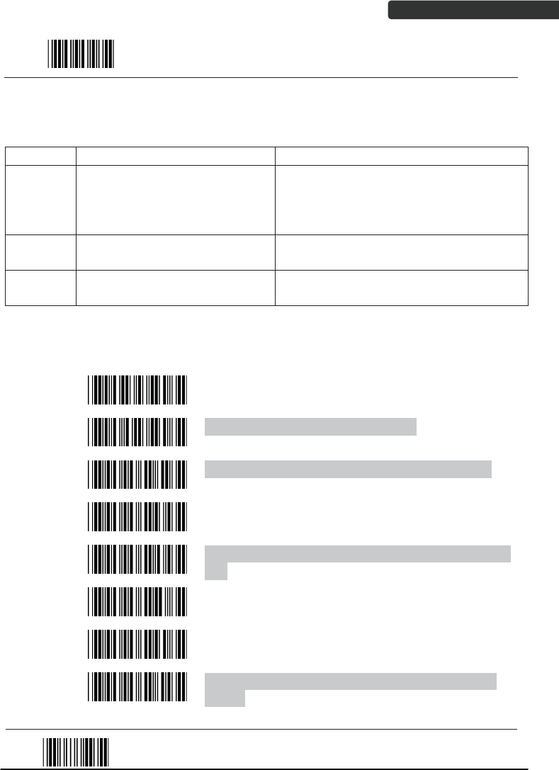
There are 7 kinds of barcodes in the GS1 DataBar family and they are categorized into
three groups. Barcode types in the same group use the same barcodes for setting.
Group Representative Contents
Group 1 GS1 DataBar Omnidirectional
(Formally RSS-14)
GS1 DataBar Omnidirectional
GS1 DataBar Truncated
GS1 DataBar Stacked
GS1 DataBar Stacked Omnidirectional
Group 2 GS1 DataBar Limited
(Formally RSS Limited) GS1 DataBar Limited
Group 3 GS1 DataBar Expanded
(Formally RSS Expanded)
GS1 DataBar Expanded
GS1 DataBar Expanded Stacked
GS1 DataBar Omnidirectional (Formally RSS-14)
Barcode
Value Barcode Label Description
RC15 GS1 DataBar Omnidirectional enable
RD15 GS1 DataBar Omnidirectional disable
SS00 Transmit GS1 DataBar Omnidirectional check digit
SS01 Do not transmit GS1 DataBar Omnidirectional check
digit
SS02 Transmit GS1 DataBar Omnidirectional application ID
(01)
SS03 Do not transmit GS1 DataBar Omnidirectional
application ID (01)
SS05 GS1 DataBar Omnidirectional /EAN-128 emulation
enable
SS04 GS1 DataBar Omnidirectional /EAN-128 emulation
disable
End Of Configuration
USER’S MANUAL
Wireless Handheld Gun Type Scanner
78
Start Of Configuration
GS1 DataBar Limited (Formally RSS Limited)
Barcode
Value Barcode Label Description
RC16 GS1 DataBar Limited enable
RD16 GS1 DataBar Limited disable
SS10 Transmit GS1 DataBar Limited check digit
SS11 Don’t transmit GS1 DataBar Limited check digit
SS12 Transmit GS1 DataBar limited application ID (01)
SS13 Do not transmit GS1 DataBar limited application ID
End Of Configuration

USER’S MANUAL
Wireless Handheld Gun Type Scanner 79
Start Of Configuration
GS1 DataBar Expanded (Formally RSS Expanded)
Barcode
Value Barcode Label Description
RC17 GS1 DataBar Expanded enable
RD17 GS1 DataBar Expanded disable
SS07 GS1 DataBar Expanded/EAN-128 emulation enable
SS06 GS1 DataBar Expanded/EAN-128 emulation disable
SS08 GS1 DataBar Expanded check digital enable
SS09 GS1 DataBar Expanded check digital disable
SS16 Transmit GS1 DataBar Expanded application ID (01)
SS17 Do not transmit GS1 DataBar Expanded application
ID
End Of Configuration

USER’S MANUAL
Wireless Handheld Gun Type Scanner
80
Start Of Configuration
Data Editing
1. Identifier Code
Barcode
Value Barcode Label Description
IS00 Disable identifier code
IS01 Enable identifier code table as factory standard
IS03 Enable identifier code table as AIM standard.
CI01 Code 39 identifier code setting
CI02 ITF 2 of 5 identifier code setting
CI03 Chinese Post Code identifier code setting
CI04 UPC-E identifier code setting
CI05 UPC-A identifier code setting
CI06 EAN-13 identifier code setting
CI07 EAN-8 identifier code setting
SET
Confirm to save this setting (required for reading full
ASCII table and length setting)
End Of Configuration

USER’S MANUAL
Wireless Handheld Gun Type Scanner 81
Start Of Configuration
Barcode
Value Barcode Label Description
CI08 Codabar identifier code setting
CI09 Code 128 identifier code setting
CI10 Code 93 identifier code setting
CI11 MSI identifier code setting
CI12 GS1 DataBar Omnidirectional identifier code setting
CI13 GS1 DataBar Limited identifier code setting
CI14 GS1 DataBar expanded identifier code setting
CI15 Industrial 2 of 5 identifier code setting
CI16 Code 11 Identifier code setting
CI17 Standard 2 of 5 identifier code setting
CI18 Matrix 2 of 5 identifier code setting
SET
Confirm to save this setting (required for reading full
ASCII table and length setting)
End Of Configuration
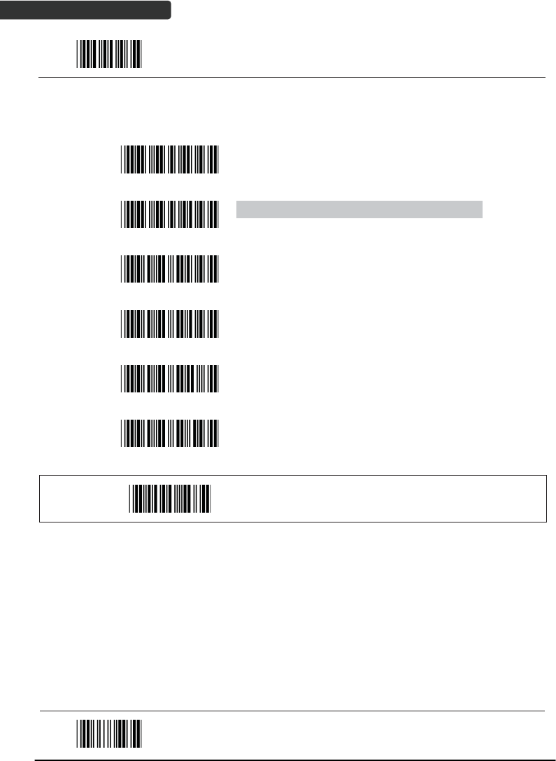
USER’S MANUAL
Wireless Handheld Gun Type Scanner
82
Start Of Configuration
2. Header and Trailer
Barcode
Value Barcode Label Description
CP11 Add code length as header enable (2 digits)
CP12 Add code length as header disable (2 digits)
HT01 Header (Preamble)
HT02 Trailer (Postamble)
HT03 Truncate header character
HT04 Truncate trailer character
SET
Confirm to save this setting (required for reading full
ASCII table and length setting)
End Of Configuration

USER’S MANUAL
Wireless Handheld Gun Type Scanner 83
Start Of Configuration
Full ASCII Code 39 Table
Code 39 ASCII
Hexa
-
code
Code 39 ASCII Hexa-
code
Full ASCII ---NUL 00
Full ASCII ---SI
Function key-----“Shift”
0F
Full ASCII ---SOH
Function key-----“Ins”
01
Full ASCII ---DLE
Function key-----
“5(num)”
10
Full ASCII ---STX
Function key-----“Del”
02
Full ASCII ---DC1
Function key-----“F1”
11
Full ASCII ---ETX
Function key-----“Home”
03
Full ASCII ---DC2
Function key-----“F2”
12
Full ASCII ---EOT
Function key-----“End”
04
Full ASCII ---DC3
Function key-----“F3”
13
Full ASCII ---ENQ
Function key-----“Up
arrow”
05
Full ASCII ---DC4
Function key-----“F4”
14
Full ASCII ---ACK
Function key-----“Down
arrow”
06
Full ASCII ---NAK
Function key-----“F5”
15
Full ASCII ---BEL
Function key-----“Left
arrow”
07
Full ASCII ---SYN
Function key-----“F6”
16
Full ASCII ---BS
Function key-----
“Backspace”
08
Full ASCII ---ETB
Function key-----“F7”
17
Full ASCII ---HT
Function key-----“TAB”
09
Full ASCII ---CAN
Function key-----“F8”
18
Full ASCII ---LF
Function key-----“Enter
(alpha numeric)”
0A
Full ASCII ---EN
Function key-----“F9”
19
Full ASCII ---VT
Function key-----“right
arrow”
0B
Full ASCII ---SUB
Function key-----“F10”
1A
Full ASCII ---FF
Function key-----“PgUp”
0C
Full ASCII ---ESC
Function key-----“F11”
1B
Full ASCII ---CR
Function key-----
“Enetr(num.)”
0D
Full ASCII ---FS
Function key-----“F12”
1C
Full ASCII ---SO
Function key-----“PgDn”
0E
Full ASCII ---GS
Function key-----“ESC”
1D
End Of Configuration

USER’S MANUAL
Wireless Handheld Gun Type Scanner
84
Start Of Configuration
Full ASCII Code 39 Table (continued)
Code 39 ASCII Hexa-
code Code 39 ASCII Hexa-
code
Full ASCII ---RS
Function key-----“CTL(L)”
1E
Full ASCII ---- 2D
Full ASCII ---US
Function key-----“ALT(L)”
1F
Full ASCII ---. 2E
Full ASCII ---SP 20
Full ASCII ---/ 2F
Full ASCII ---! 21
Full ASCII ---0 30
Full ASCII ---“ 22
Full ASCII ---1 31
Full ASCII ---# 23
Full ASCII ---2 32
Full ASCII ---$ 24
Full ASCII ---3 33
Full ASCII ---% 25
Full ASCII ---4 34
Full ASCII ---& 26
Full ASCII ---5 35
Full ASCII ---‘ 27
Full ASCII ---6 36
Full ASCII --- ( 28
Full ASCII ---7 37
Full ASCII ---) 29
Full ASCII ---8 38
Full ASCII ---* 2A
Full ASCII ---9 39
Full ASCII ---+ 2B Full ASCII ---: 3A
Full ASCII ---, 2C Full ASCII ---; 3B
End Of Configuration

USER’S MANUAL
Wireless Handheld Gun Type Scanner 85
Start Of Configuration
Full ASCII Code 39 Table (continued)
Code 39 ASCII Hexa-
code Code 39 ASCII Hexa-
code
Full ASCII ---< 3C
Full ASCII ---K 4B
Full ASCII ---= 3D
Full ASCII ---L 4C
Full ASCII ---> 3E
Full ASCII ---M 4D
Full ASCII ---? 3F
Full ASCII ---N 4E
Full ASCII ---@ 40
Full ASCII ---O 4F
Full ASCII ---A 41
Full ASCII ---P 50
Full ASCII ---B 42
Full ASCII ---Q 51
Full ASCII ---C 43
Full ASCII ---R 52
Full ASCII ---D 44
Full ASCII ---S 53
Full ASCII ---E 45
Full ASCII ---T 54
Full ASCII ---F 46
Full ASCII ---U 55
Full ASCII ---G 47
Full ASCII ---V 56
Full ASCII ---H 48
Full ASCII ---W 57
Full ASCII ---I 49
Full ASCII ---X 58
Full ASCII ---J 4A
Full ASCII ---Y 59
End Of Configuration

USER’S MANUAL
Wireless Handheld Gun Type Scanner
86
Start Of Configuration
Full ASCII Code 39 Table (continued)
Code 39 ASCII Hexa-
code Code 39 ASCII Hexa-
code
Full ASCII ---Z 5A
Full ASCII ---i 69
Full ASCII ---[ 5B
Full ASCII ---j 6A
Full ASCII ---\ 5C
Full ASCII ---k 6B
Full ASCII ---] 5D
Full ASCII ---l 6C
Full ASCII ---^ 5E
Full ASCII ---m 6D
Full ASCII ---_ 5F
Full ASCII ---n 6E
Full ASCII ---` 60
Full ASCII ---o 6F
Full ASCII ---a 61
Full ASCII ---p 70
Full ASCII ---b 62
Full ASCII ---q 71
Full ASCII ---c 63
Full ASCII ---r 72
Full ASCII ---d 64
Full ASCII ---s 73
Full ASCII ---e 65
Full ASCII ---t 74
Full ASCII ---f 66
Full ASCII ---u 75
Full ASCII ---g 67
Full ASCII ---v 76
Full ASCII ---h 68
Full ASCII ---w 77
End Of Configuration
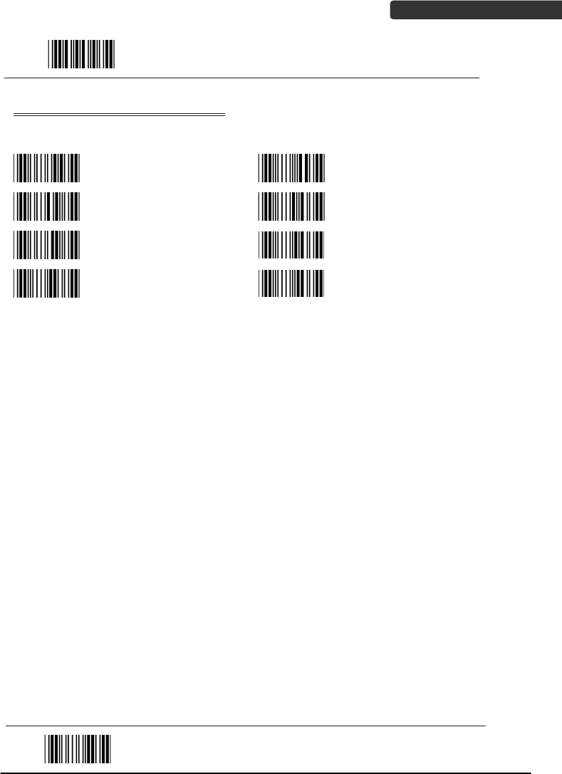
USER’S MANUAL
Wireless Handheld Gun Type Scanner 87
Start Of Configuration
Full ASCII Code 39 Table (continued)
Code 39 ASCII Hexa-
code Code 39 ASCII Hexa-
code
Full ASCII ---x 78
Full ASCII ---| 7C
Full ASCII ---y 79
Full ASCII ---} 7D
Full ASCII ---z 7A
Full ASCII ---~ 7E
Full ASCII ---{ 7B
Full ASCII ---DEL 7F
End Of Configuration

Wireless Handheld Gun Type Scanner
88
USER’S MANUAL
Appendix 1: USB Virtual COM Driver Installation
Contact your distributor to get the driver and follow the steps below to enable USB
virtual COM port.
1. Connect the handheld scanner and the host (e.g. a PC) with a USB interface cable.
2. Enable USB virtual COM port with programming barcode on page 32.
3. After the programming, the host would request driver installation. Browse your
files to locate the driver and start installation.
4. The USB virtual COM port is ready for use after driver installation.
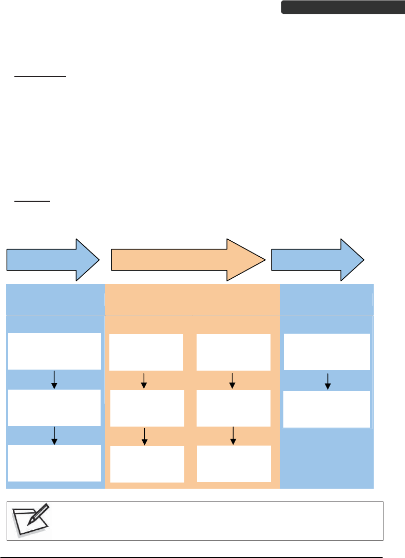
USER’S MANUAL
Wireless Handheld Gun Type Scanner 89
Appendix 2: Barcode Length Setting
Introduction
The length of a barcode is the number of characters it contains, including check digits.
As listed in the Default Parameters section, each barcode type has different default
length. You may change the setting by the following procedure.
To set up barcode length, the paramours to be determined are barcode type and the
desired barcode length. Barcode length is consisted of 2 digits. For numbers smaller
than 10, you need to add a “0” in the front.
Example
If the barcode length is 4 to 12 digits, the steps would be as below:
EndSet up barcode length Start
Set up minimum
barcode length
Start of Configuration Set up maximum
barcode length End of Configuration
Scan the “Start of
configuration” barcode
Scan the “Set”
barcode to save this
settin
g
Scan the
“Min“ barcode
Set the “Max”
barcode
Set up the
second digit: 2
Scan the first
digit: 0
Scan the second
digit: 4
Turn to the page of the
barcode type to be set
u
p
Read the “Full ASCII
code 39” barcode
Set up the first
digit: 1
Scan the “End of
configuration”
barcode
Use the ASCII table (Appendix 4) to set up barcode length. Be sure to enable
the full ASCII code 39 option before you start and read the “Set” label to set
your choice into memory.