Zebra Technologies AP6 Access Point Radio Module 6 User Manual Manual
Zebra Technologies Corporation Access Point Radio Module 6 Manual
UserManual.wiki
>
Zebra Technologies
>
AP6 User Manual
>
Manual
Contents
1.
Manual
2.
Antenna Installation Guide 050412
3.
AP 6511 Install Guide Rev B 050412
4.
AP 6521 Install Guide Rev B 050412
Manual
Navigation menu
Upload a User Manual
Namespaces
Wiki Guide
HTML
PDF
Info
Views
User Manual
Discussion / Help
Navigation
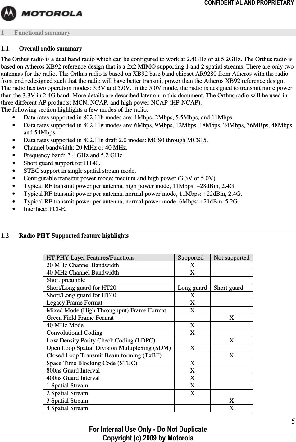
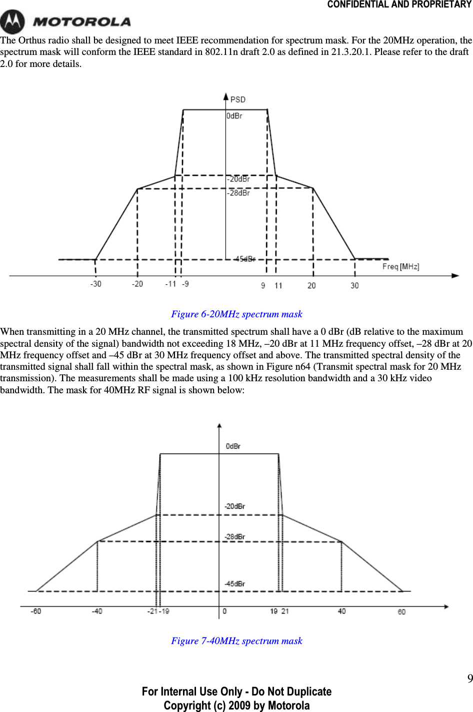
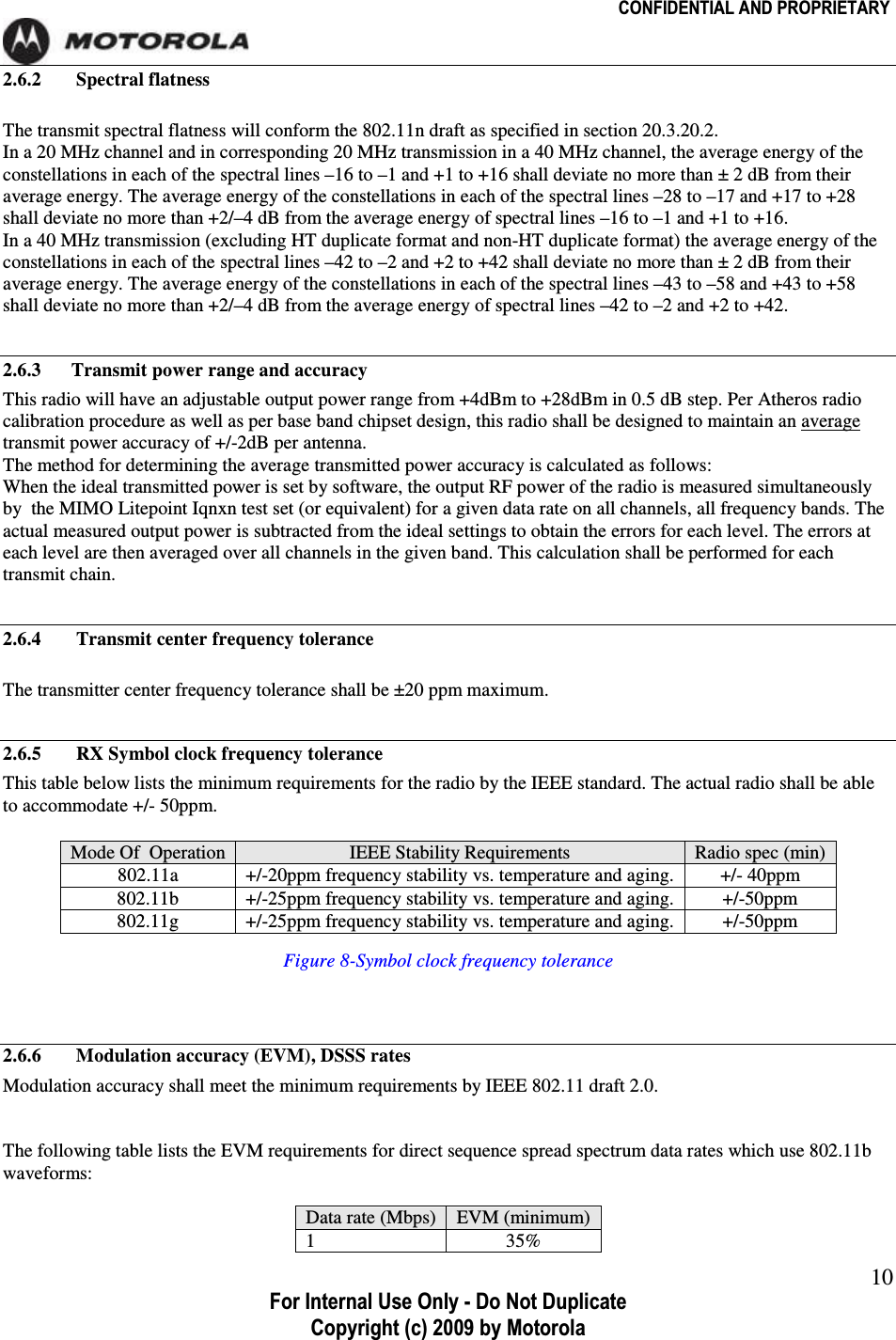
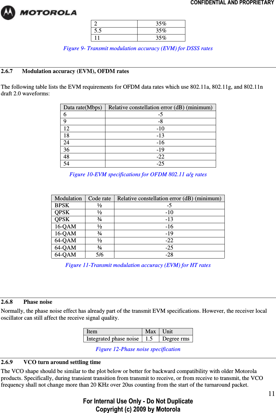
![CONFIDENTIAL AND PROPRIETARY For Internal Use Only - Do Not Duplicate Copyright (c) 2009 by Motorola 3TABLE OF CONTENTS X mG .......................................................................................................... 5 XUX vGG ............................................................................................... 5 XUY yGwoGzGG .............................................................. 5 Y l .............................................................................................................................. 7 YUX hG ............................................................................................................... 7 YUY {G ..................................................................................................... 7 YUZ yGG ..................................................................................................... 7 YUZUX hGG .......................................................................... 7 YU[ ymGG ................................................................................................ 7 YU\ jGGGGG ........................................... 7 YU\UX YU[Gno¡G ....................................................................................................... 7 YU\UY \UYGno¡G ....................................................................................................... 8 YU] {G ................................................................................................ 8 YU]UX zG .................................................................................................... 8 YU]UY zG ............................................................................................... 10 YU]UZ {GGGG .......................................................... 10 YU]U[ {GGG ........................................................ 10 YU]U\ yGzGGG ....................................................... 10 YU]U] tGGOl}tPSGkzzzG .................................................. 10 YU]U^ tGGOl}tPSGvmktG ................................................ 11 YU]U_ wG ........................................................................................................ 11 YU]U` }jvGGGG ..................................................................... 11 YU]UXW {G ......................................................................................... 12 YU]UXX sG ..................................................................................................... 13 YU]UXY jGG ............................................................................ 14 YU^ yG .................................................................................................... 15 YU^UX yGG ........................................................................... 15 YU^UY hGG ............................................................................ 18 YU^UZ uTGG .................................................................. 18 YU^U[ yGGGG ......................................................... 19 YU^U\ yGTG .......................................................... 19 YU^U] yGGGGOyjwpP ................................................. 19 YU^U^ kGGGG ................................................................. 20](https://usermanual.wiki/Zebra-Technologies/AP6.Manual/User-Guide-1412596-Page-3.png)
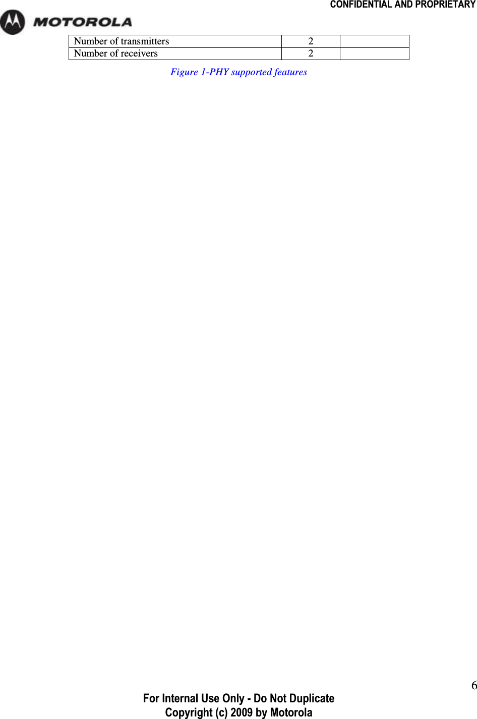
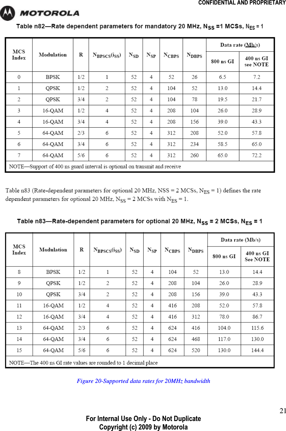
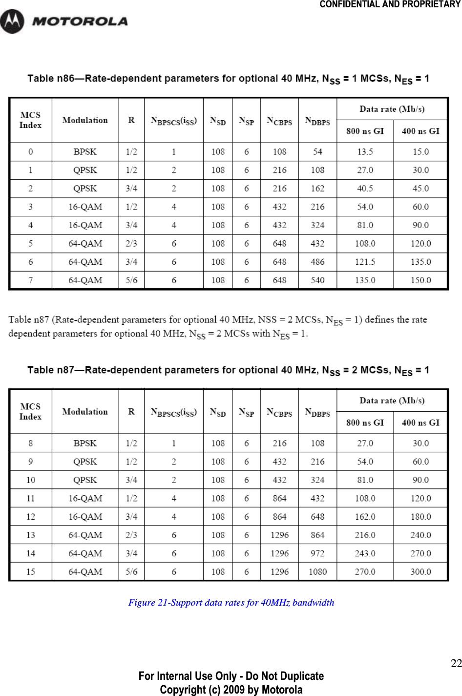
![CONFIDENTIAL AND PROPRIETARY For Internal Use Only - Do Not Duplicate Copyright (c) 2009 by Motorola 4TABLE OF FIGURES mGXTwoGG ........................................................................................ 6 mGYTwGG ................................................................................ 7 mGZTyztGGGG ............................................................... 7 mG[TYU[Gno¡G ....................................................................................................... 8 mG\T\UYGno¡GGG................................................................... 8 mG]TYWto¡GG .......................................................................................... 9 mG^T[Wto¡GG .......................................................................................... 9 mG_TzGGG ................................................................... 10 mG`TG{GGGOl}tPGGkzzzG ............................. 11 mGXWTl}tGGGvmktG_WYUXXGVG ........................................ 11 mGXXT{GGGOl}tPGGo{G ................................. 11 mGXYTwGG ................................................................................. 11 mGXZT}jvGG .................................................................................. 12 mGX[T{GG ................................................................... 13 mGX\T{GGSGZUZ}G .................................................. 14 mGX]T{GGSG\UW}G .................................................. 15 mGX^T{GGGGvGSGY[WWt¡G .............. 16 mGX_T{GGGGvGSG\YWWt¡G .............. 17 mGX`ThGjGGTGGG . 18 mGYWTzGGGGYWto¡G ............................................... 21mGYXTzGGGG[Wto¡G .................................................... 22](https://usermanual.wiki/Zebra-Technologies/AP6.Manual/User-Guide-1412596-Page-4.png)