Zebra Technologies AP6 Access Point Radio Module 6 User Manual WS5100MigGde
Zebra Technologies Corporation Access Point Radio Module 6 WS5100MigGde
Contents
- 1. Manual
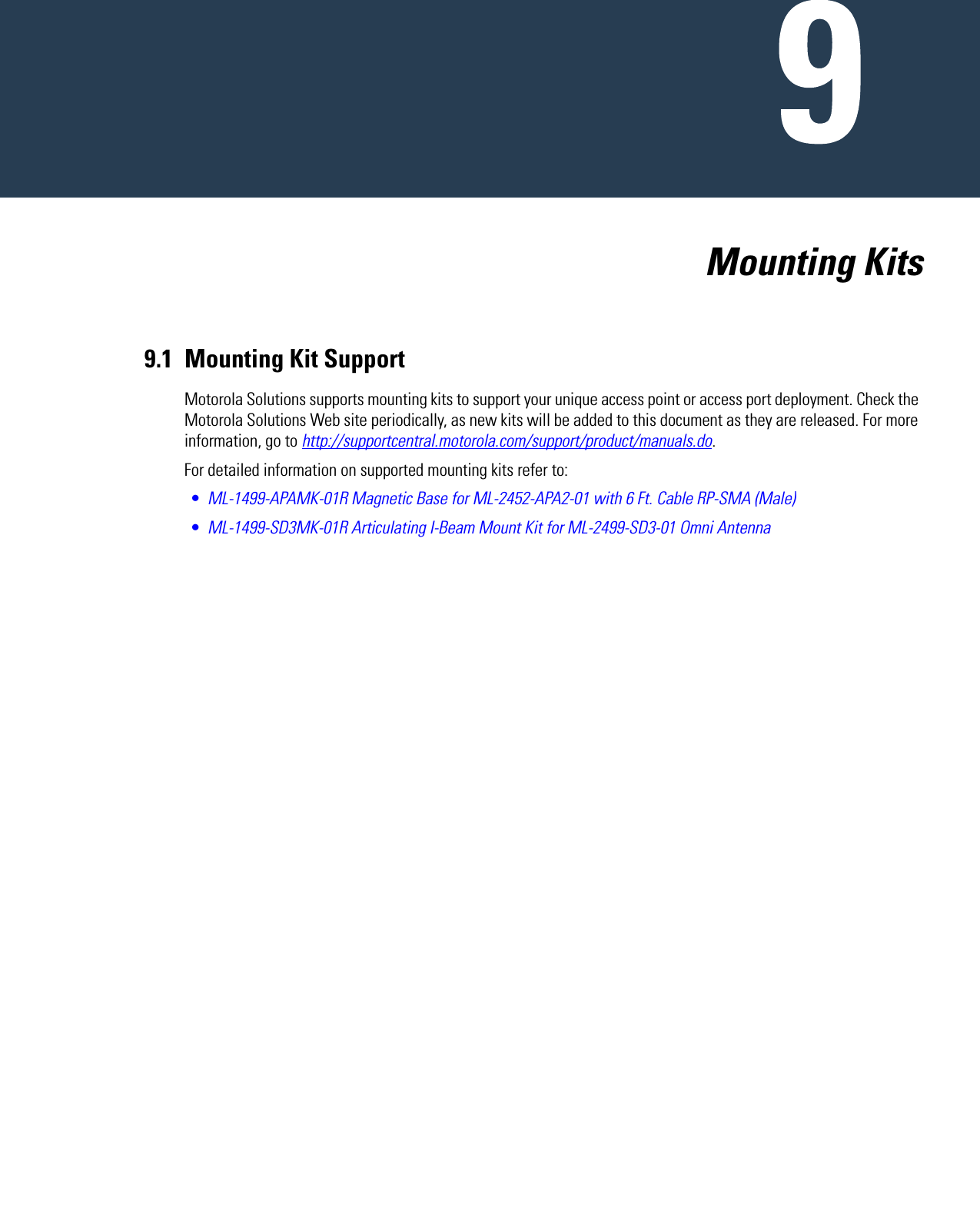
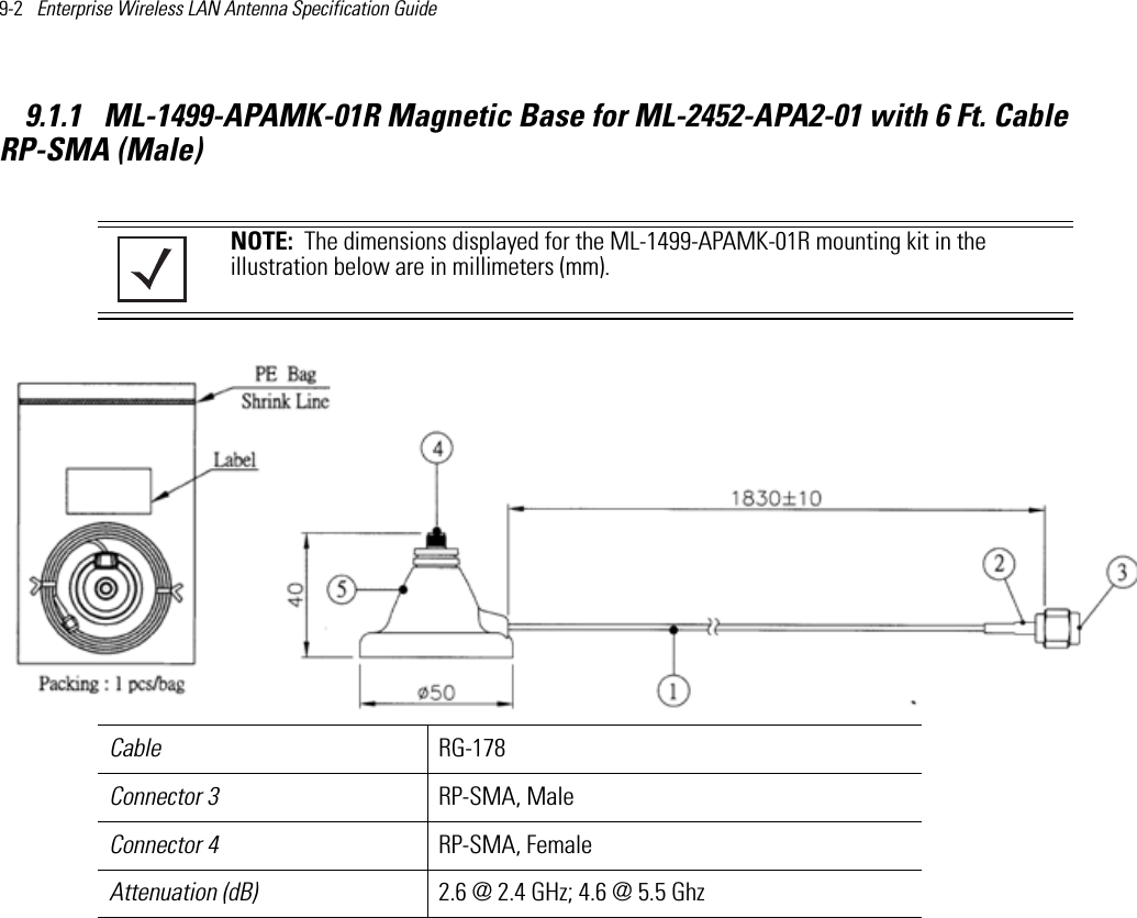
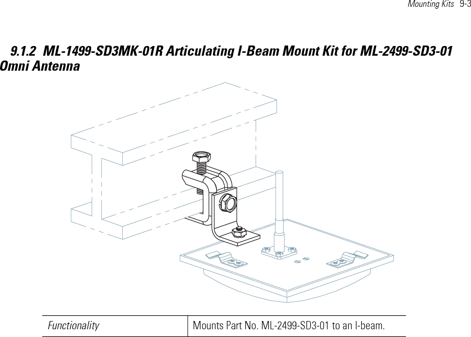
- 2. Antenna Installation Guide 050412
- 3. AP 6511 Install Guide Rev B 050412
- 4. AP 6521 Install Guide Rev B 050412
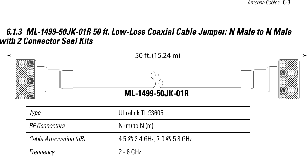
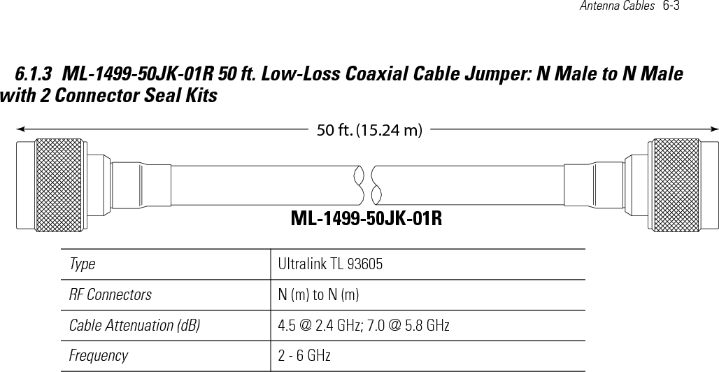
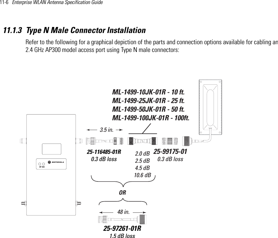
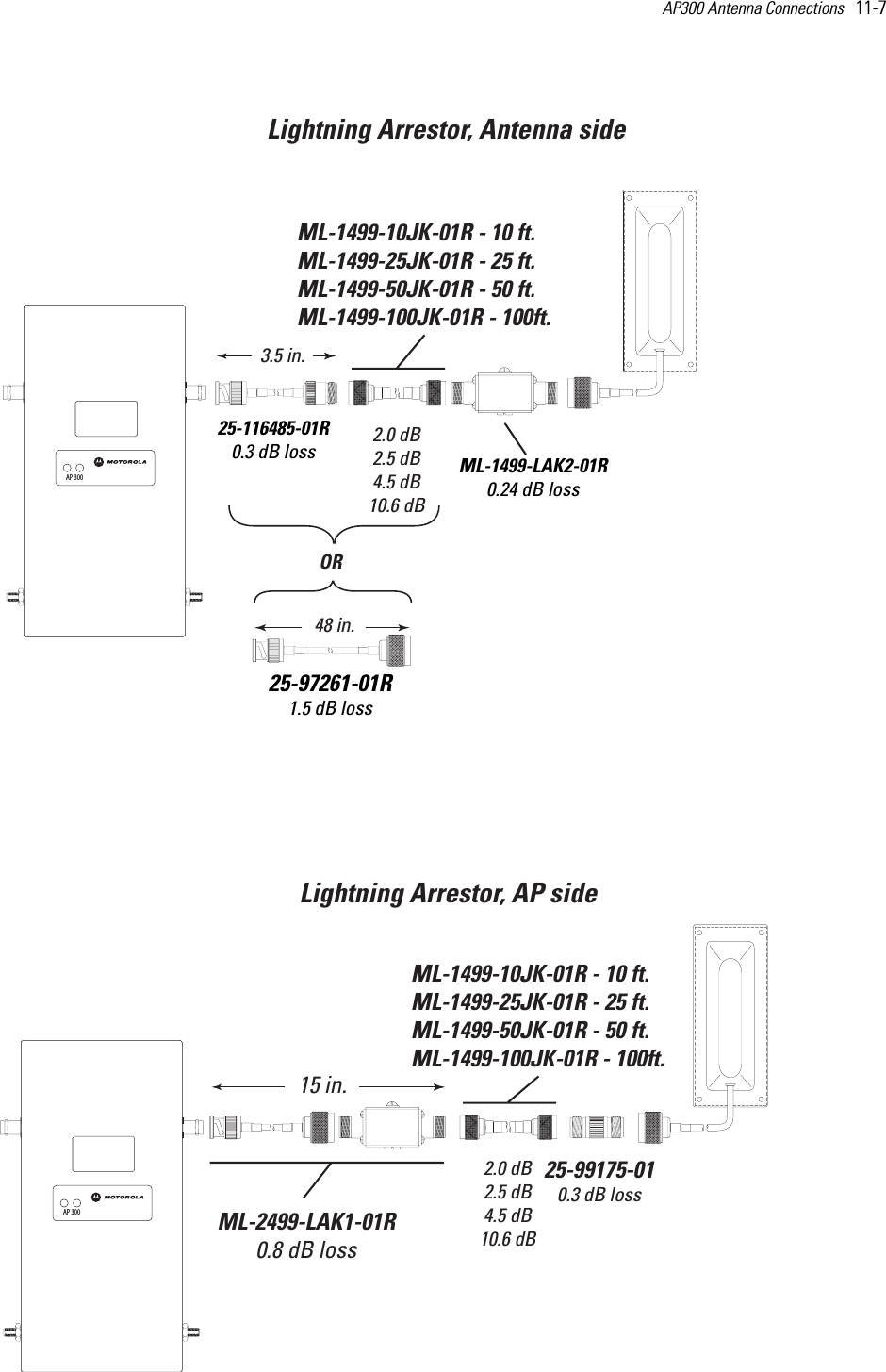
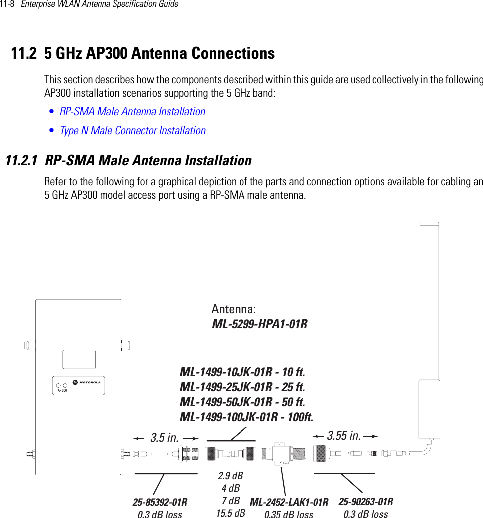
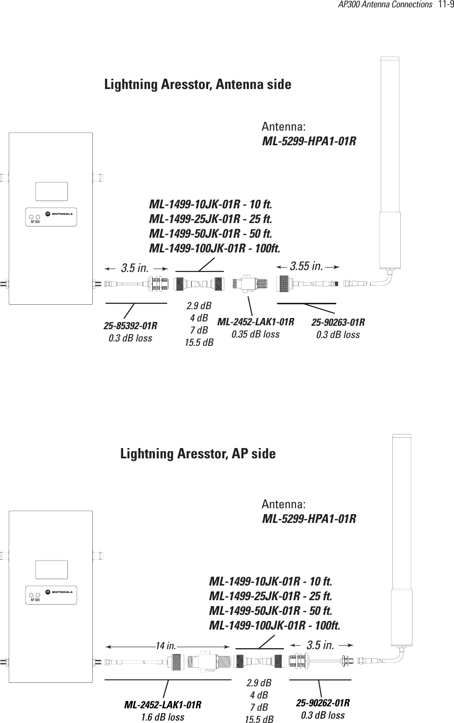
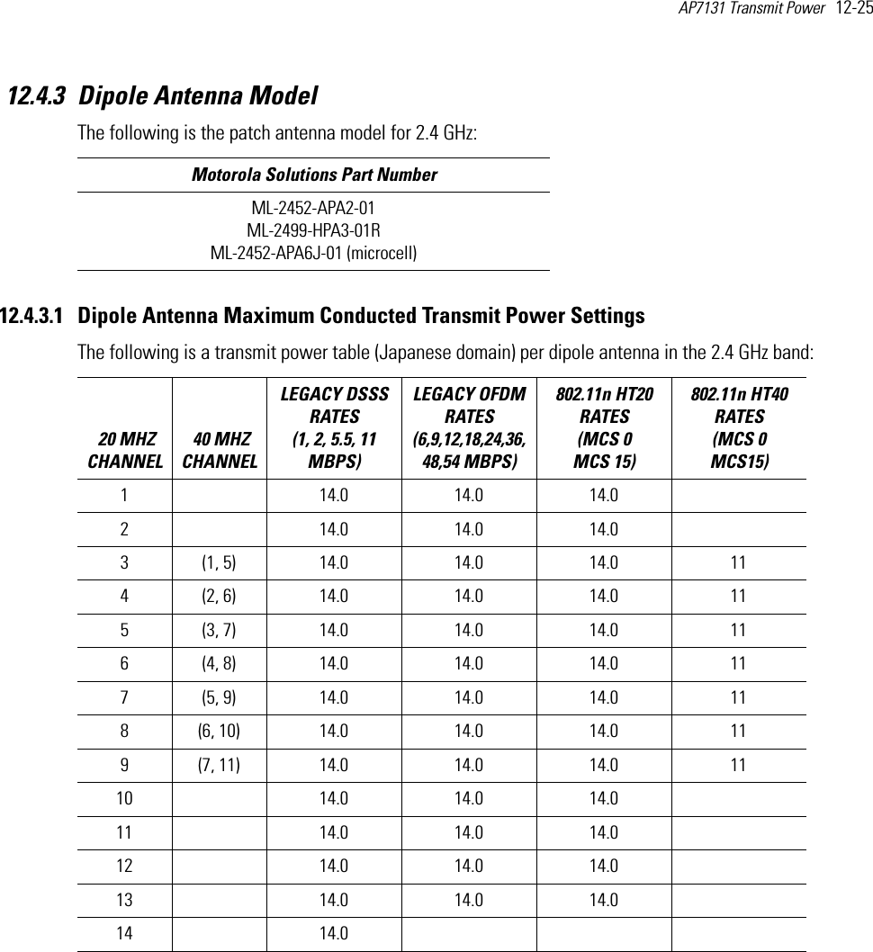
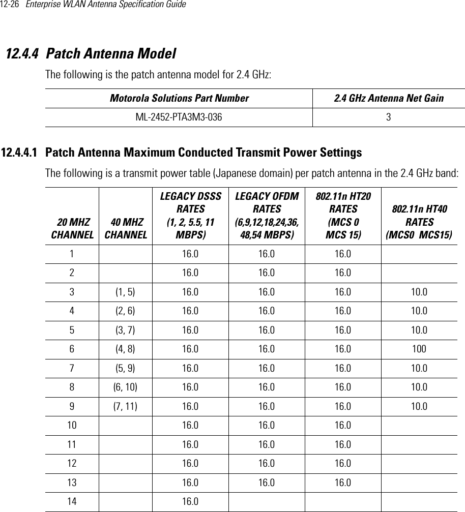
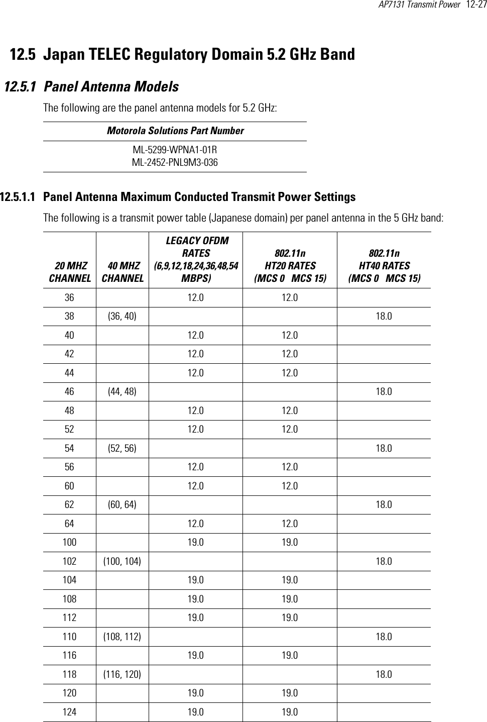
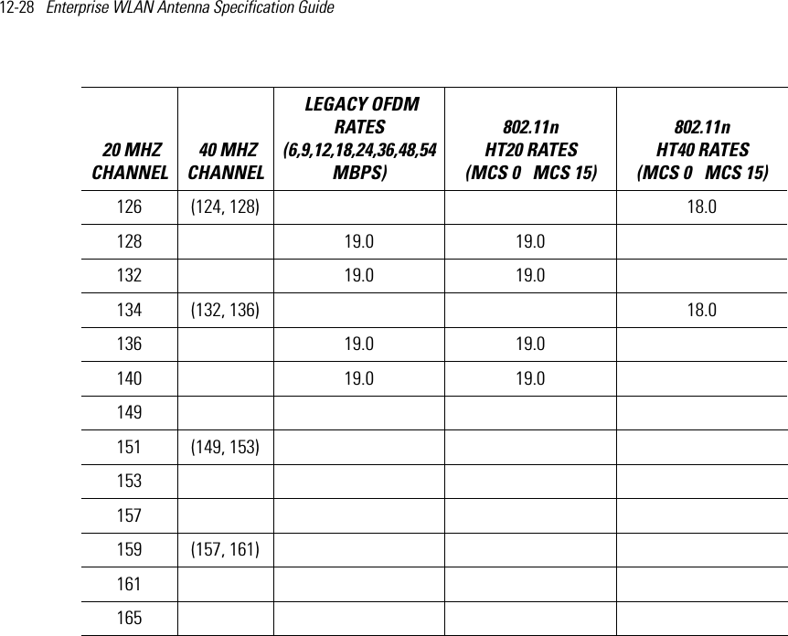
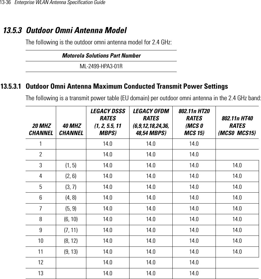
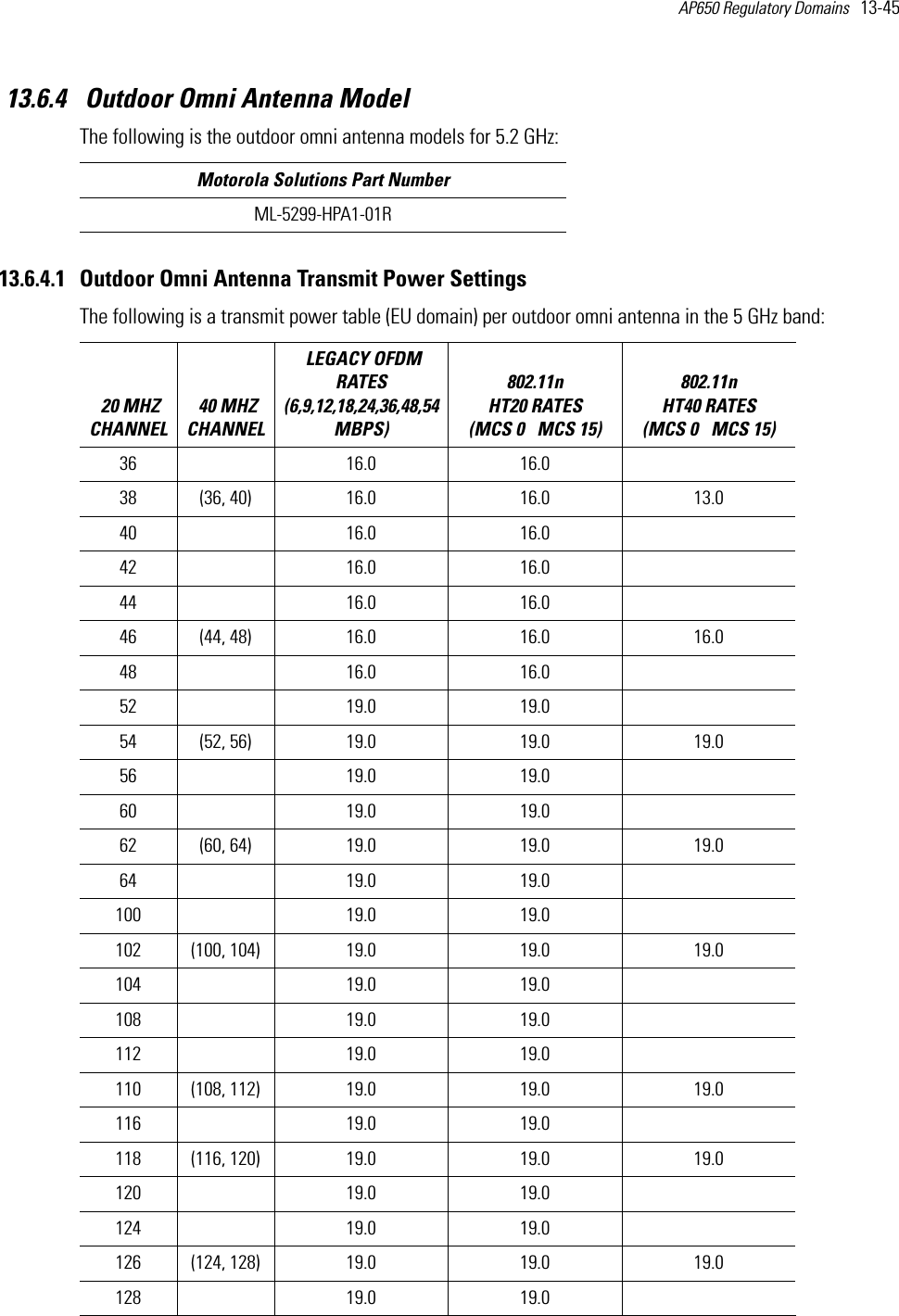
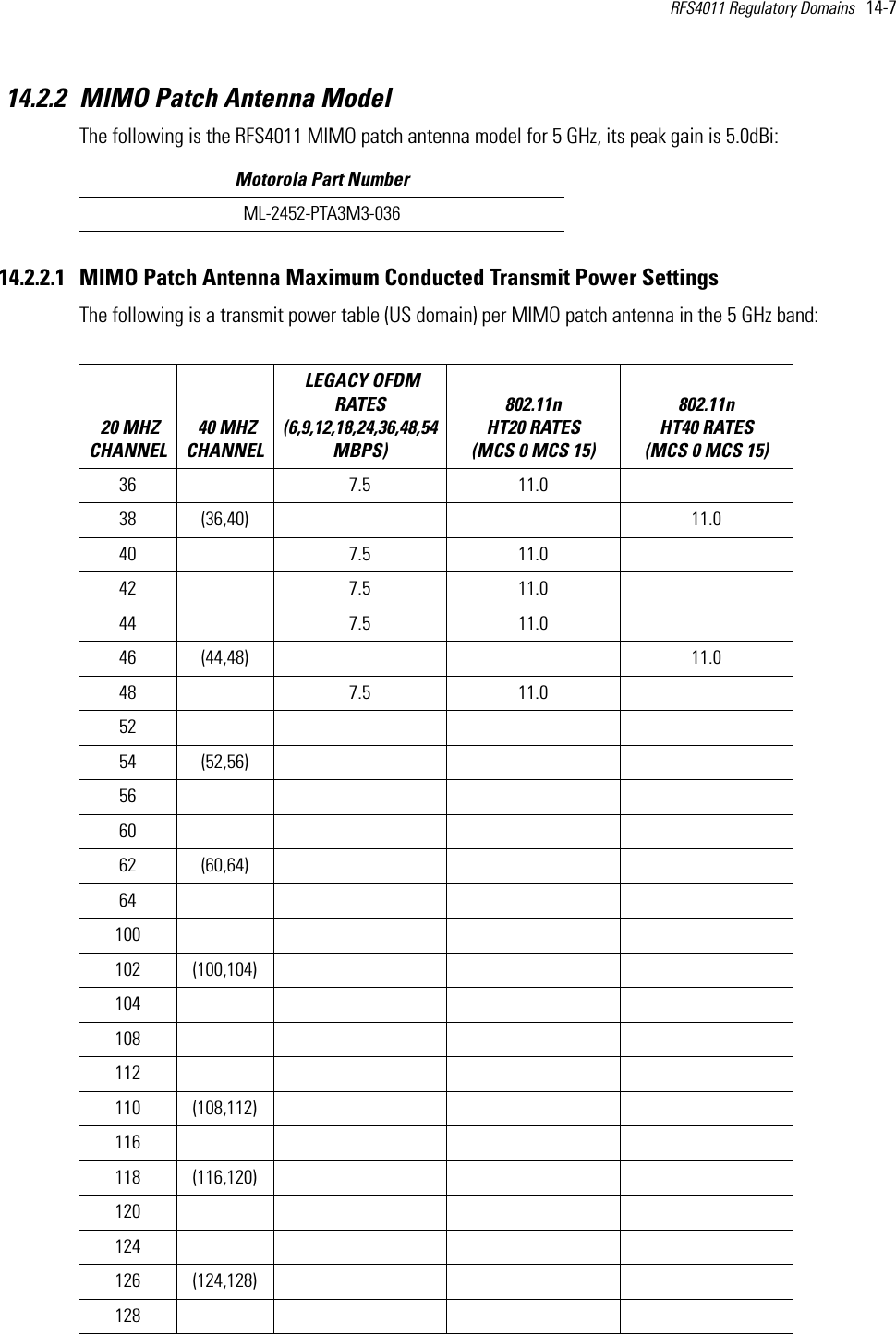
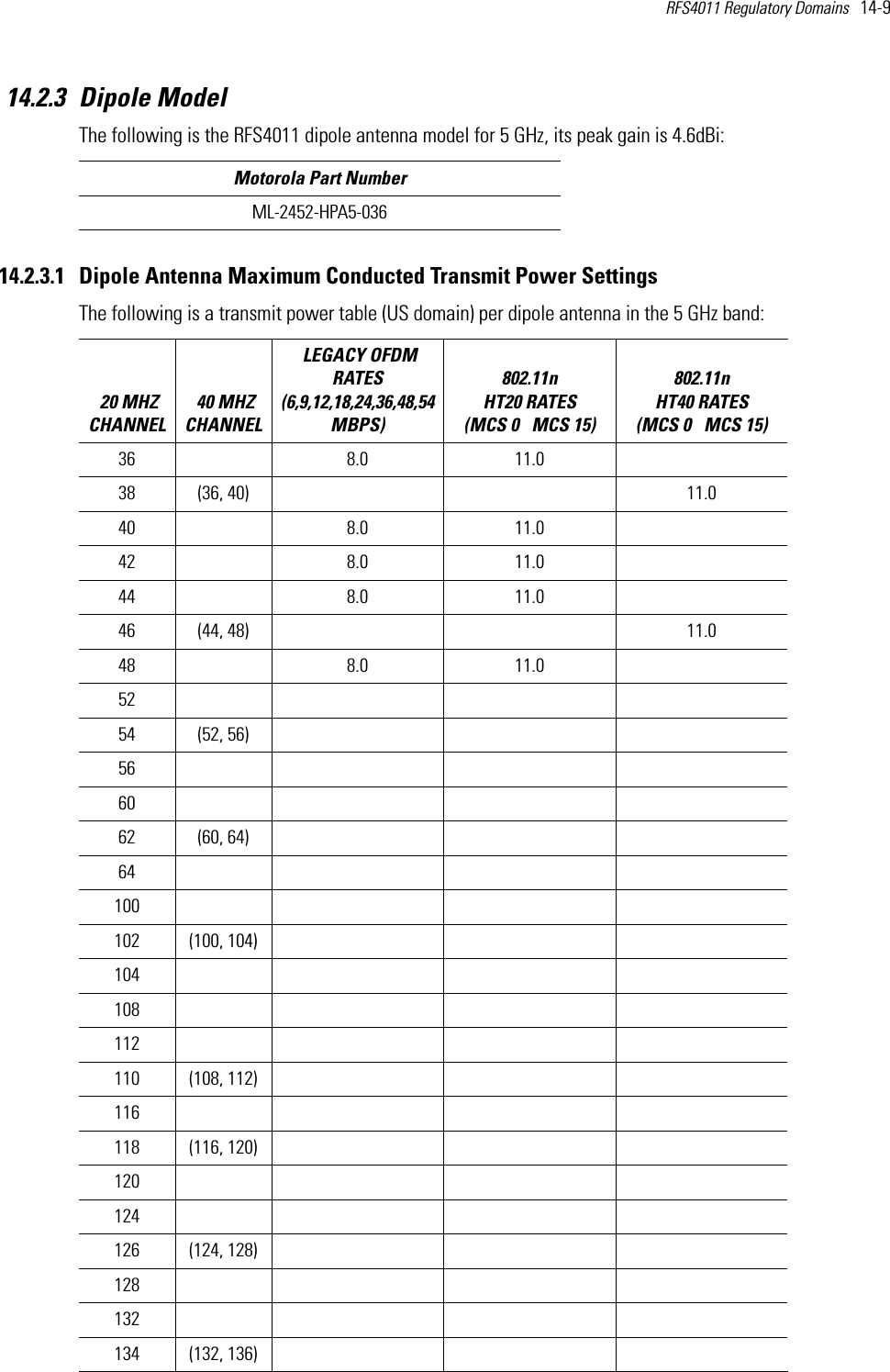
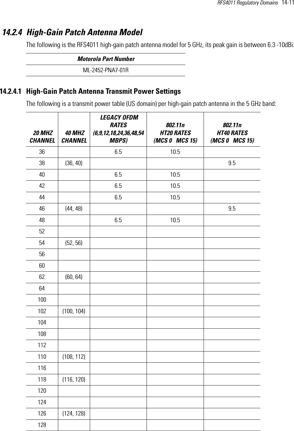
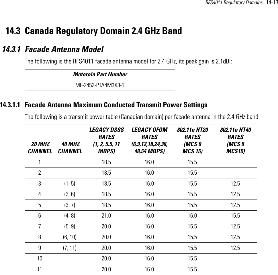
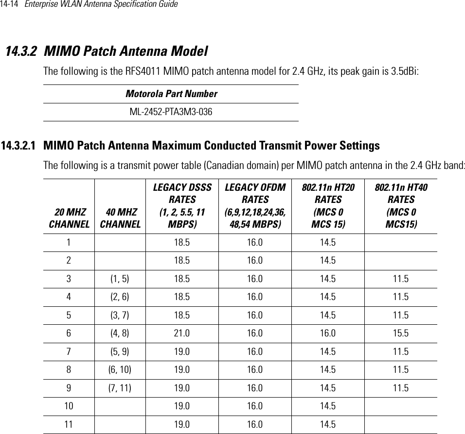
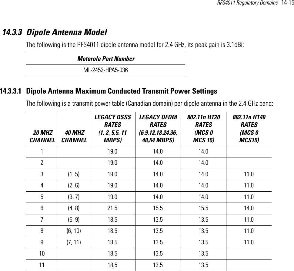
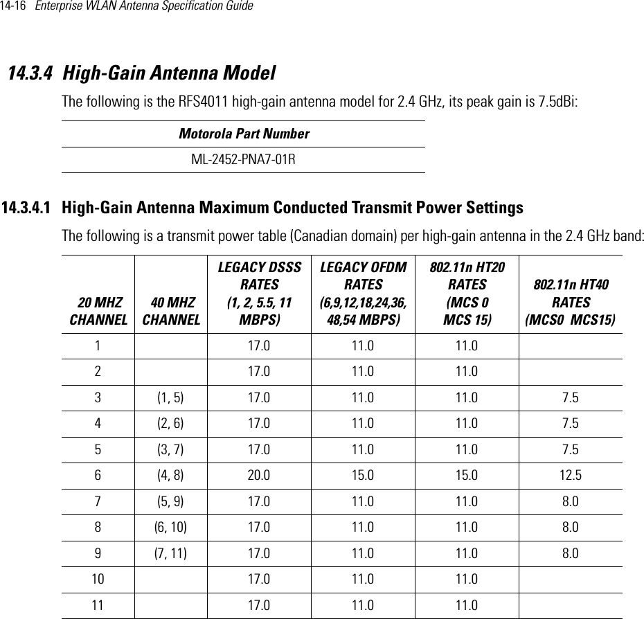
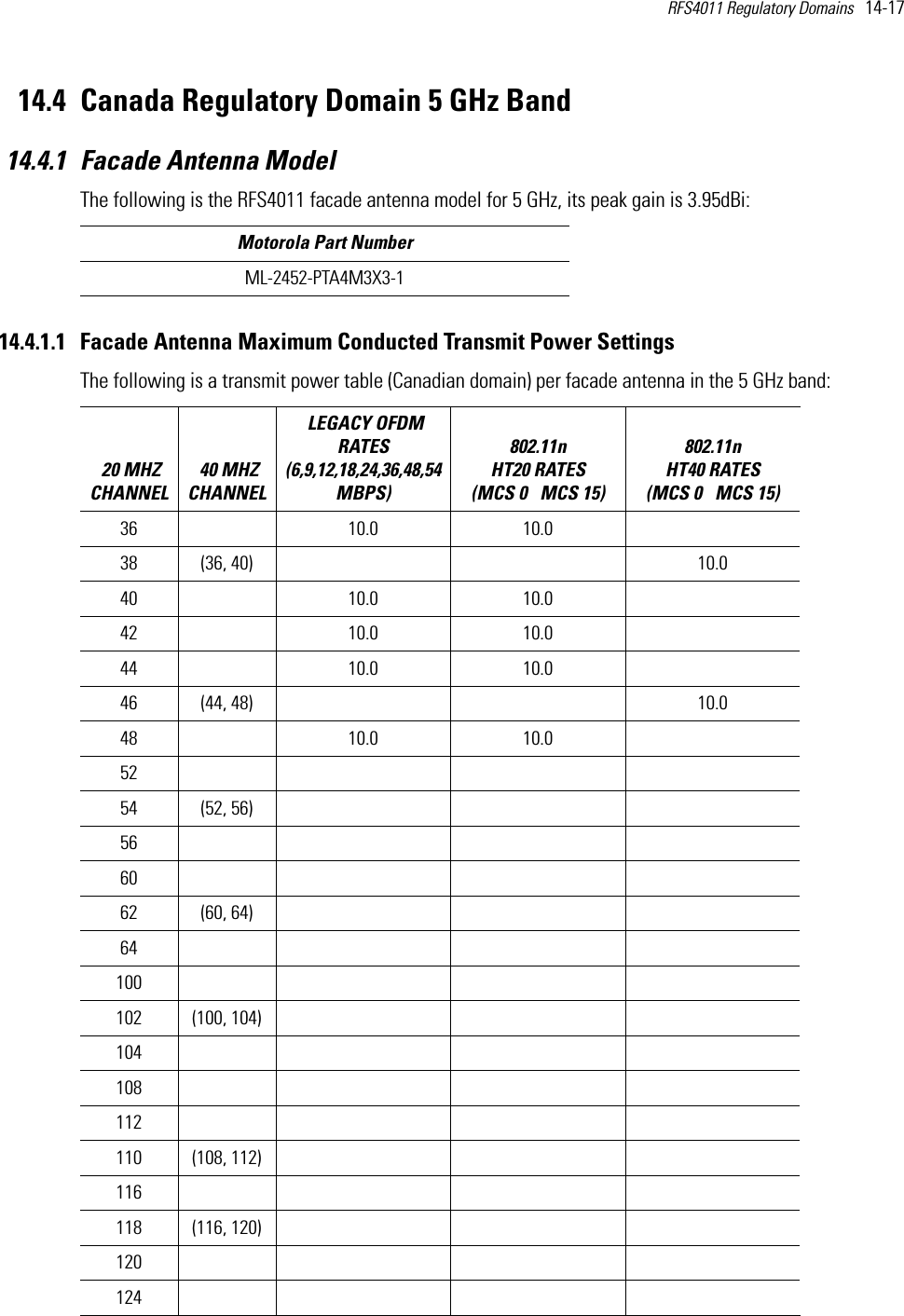
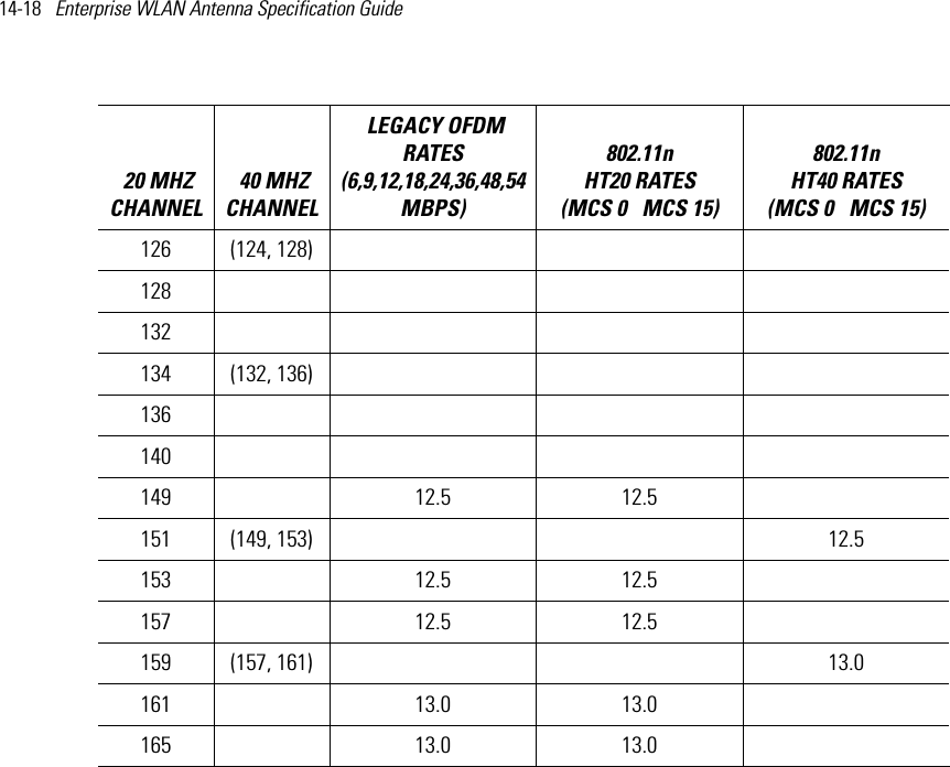
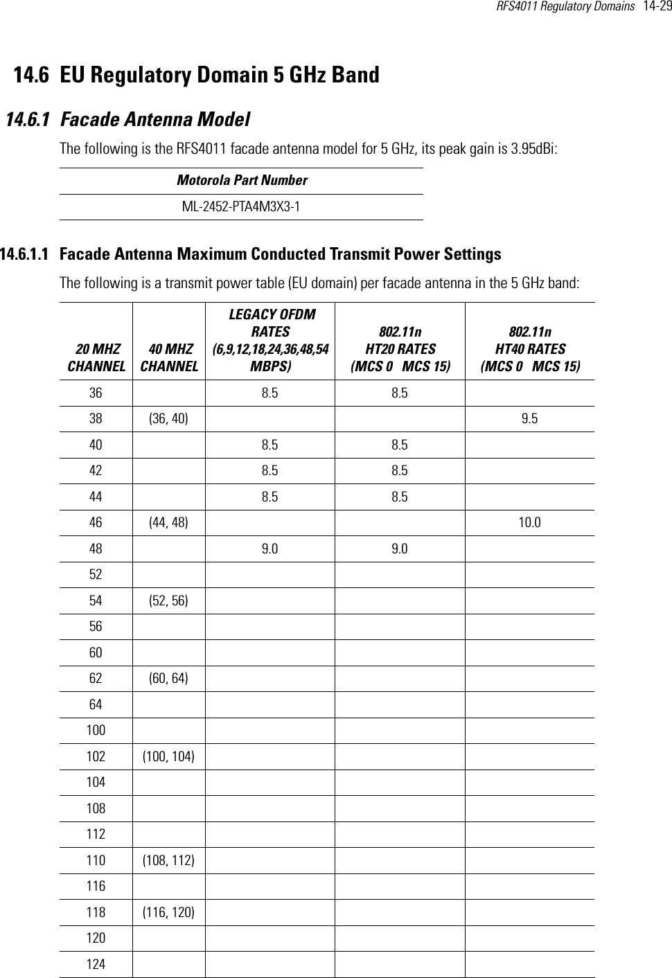
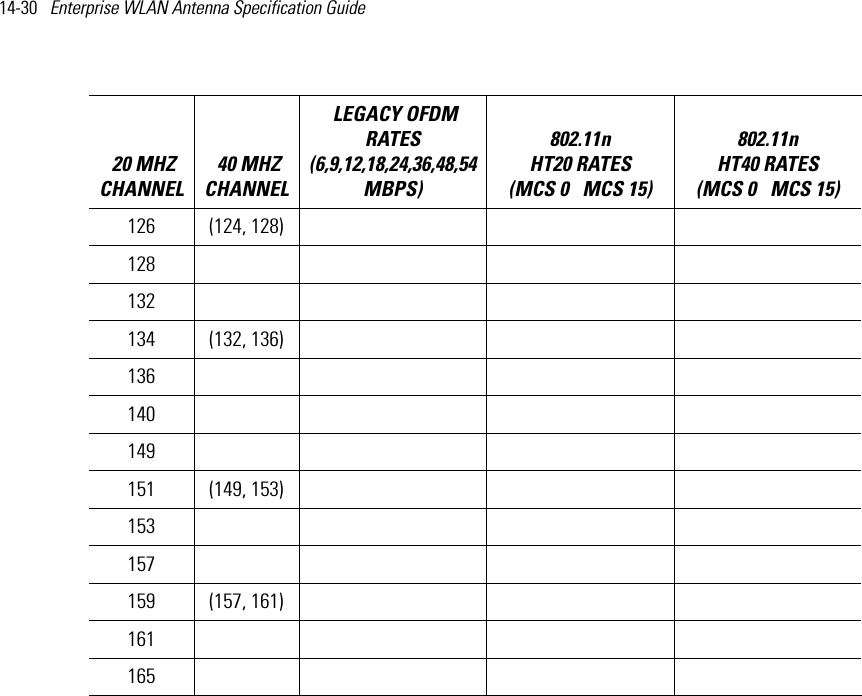
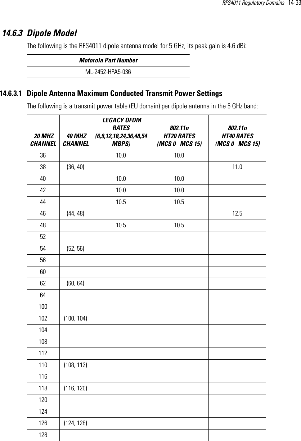
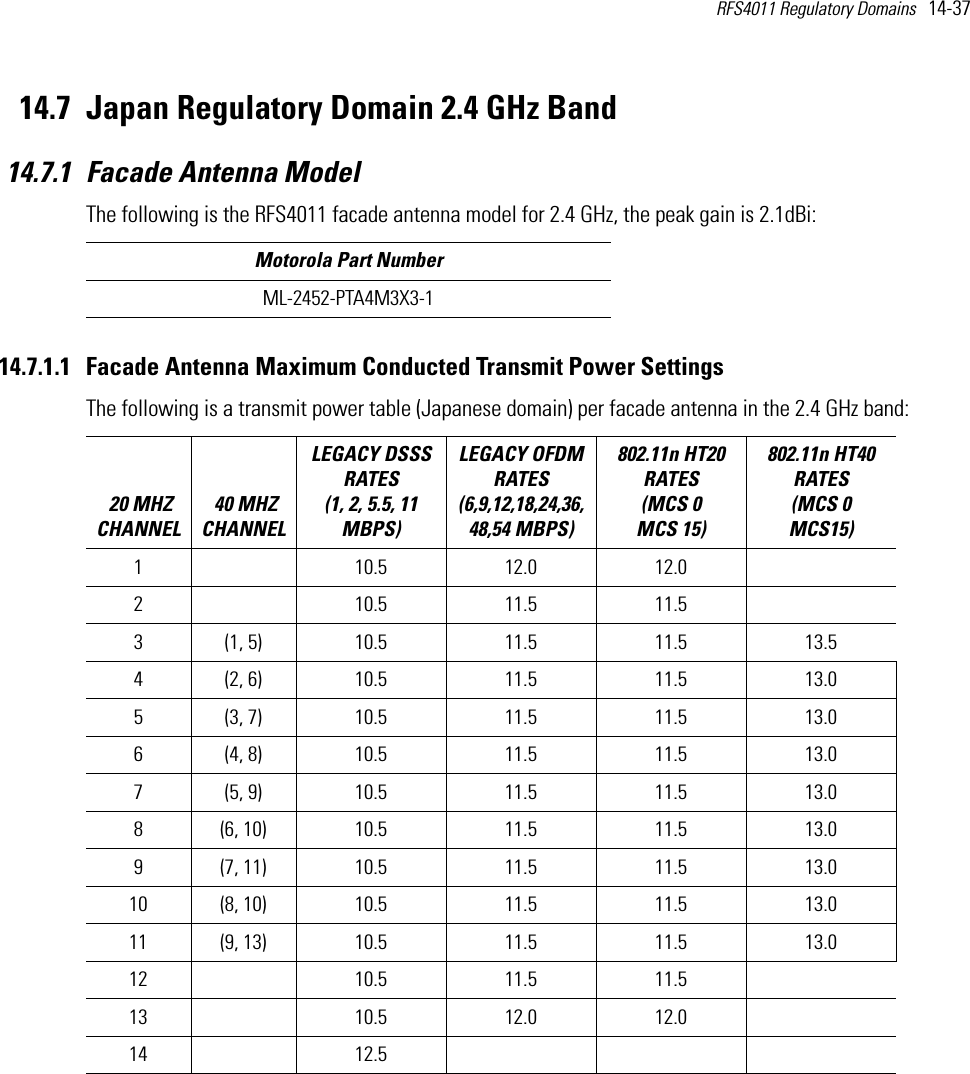
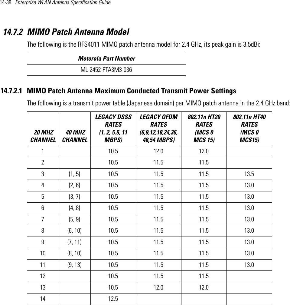
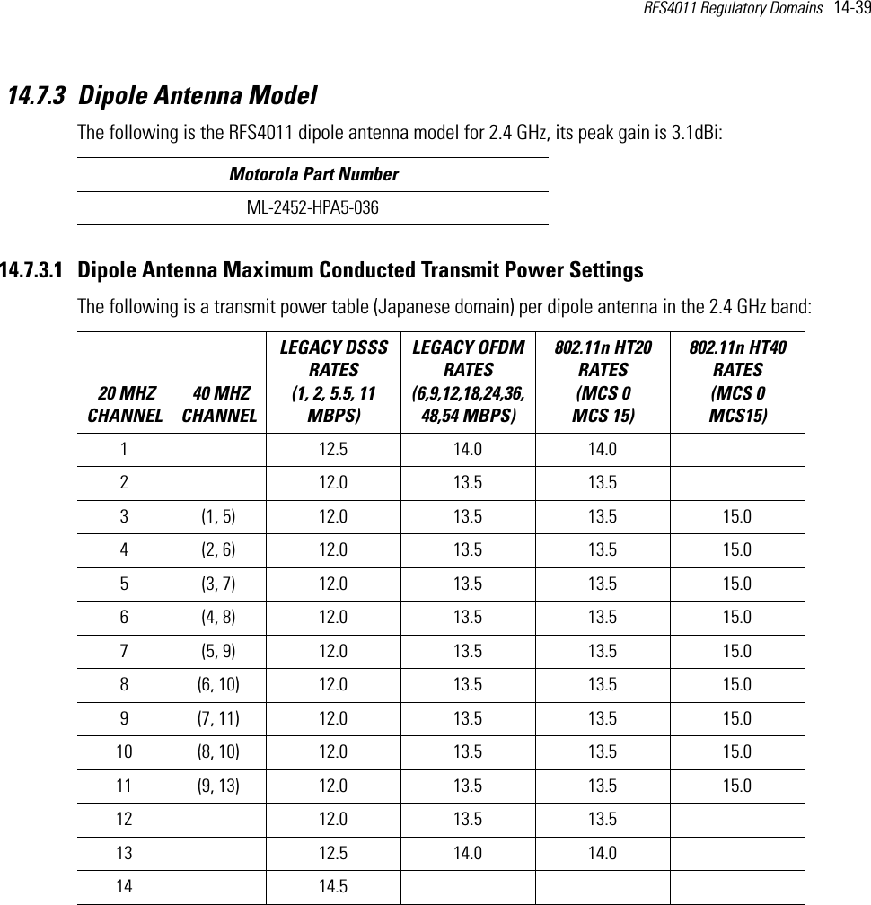
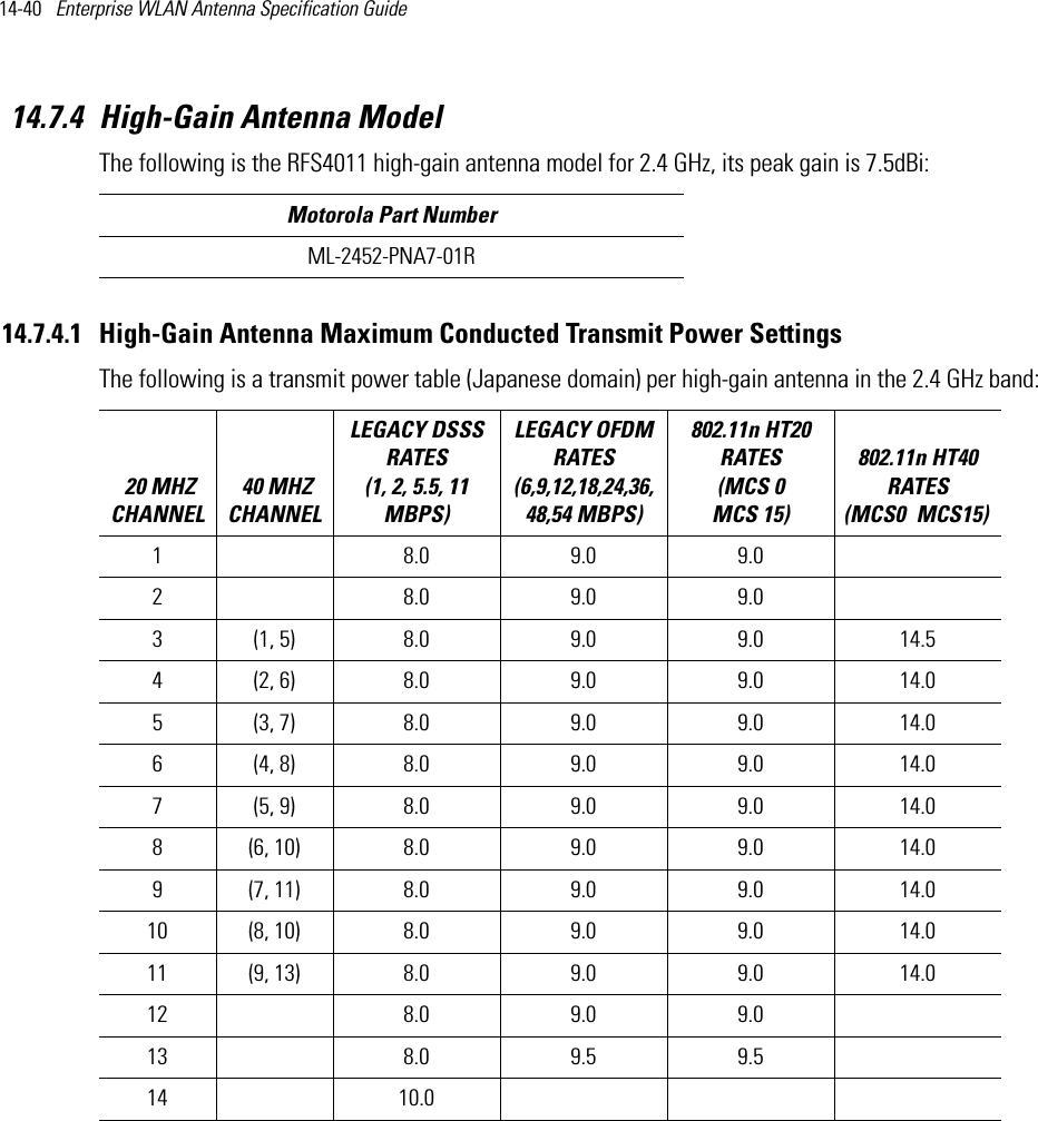
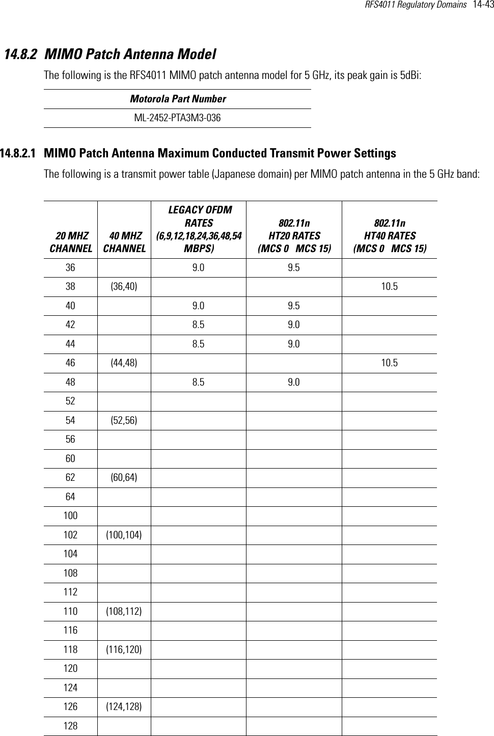
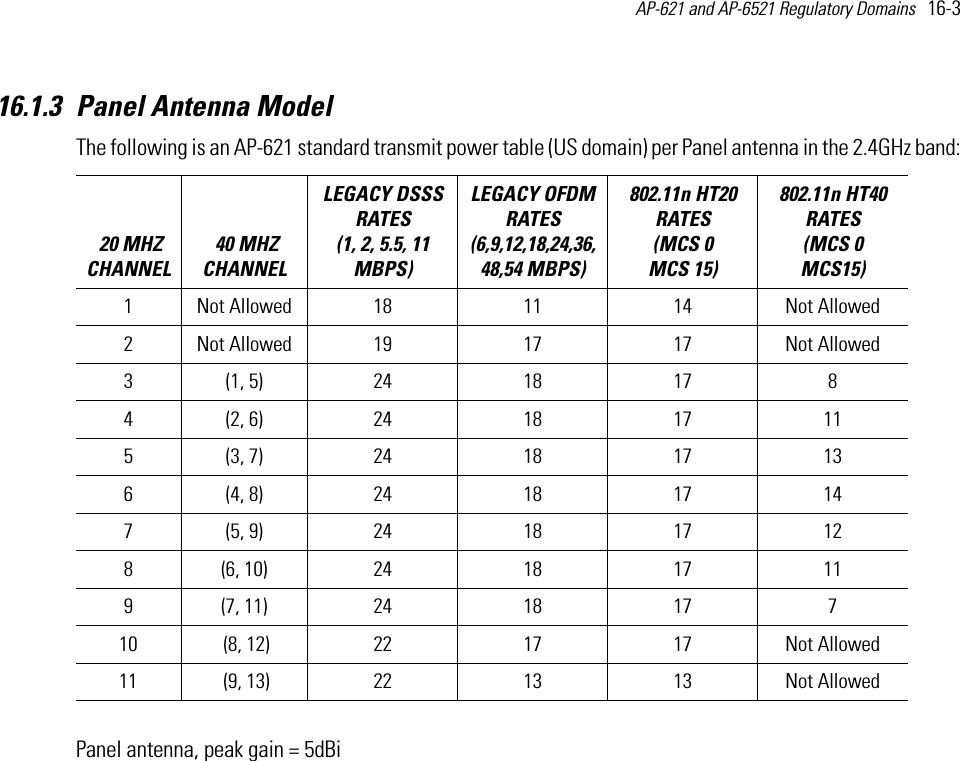
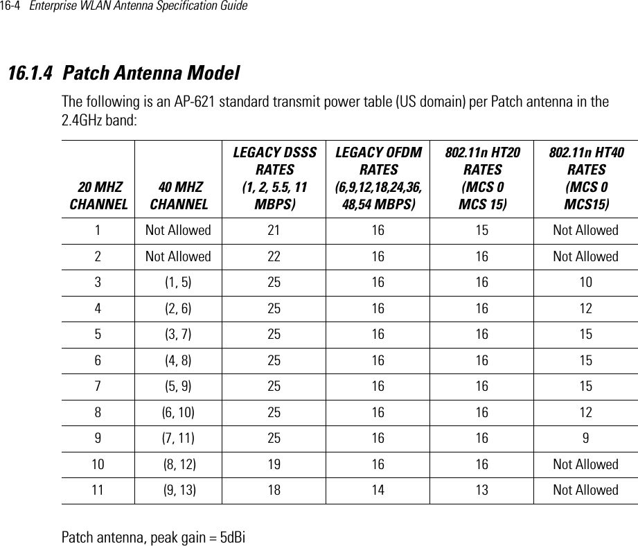
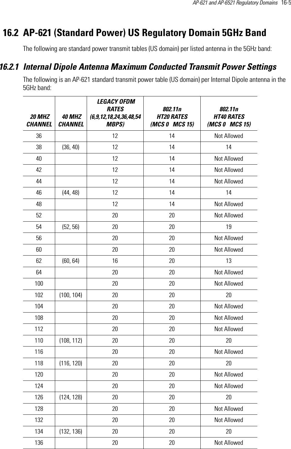
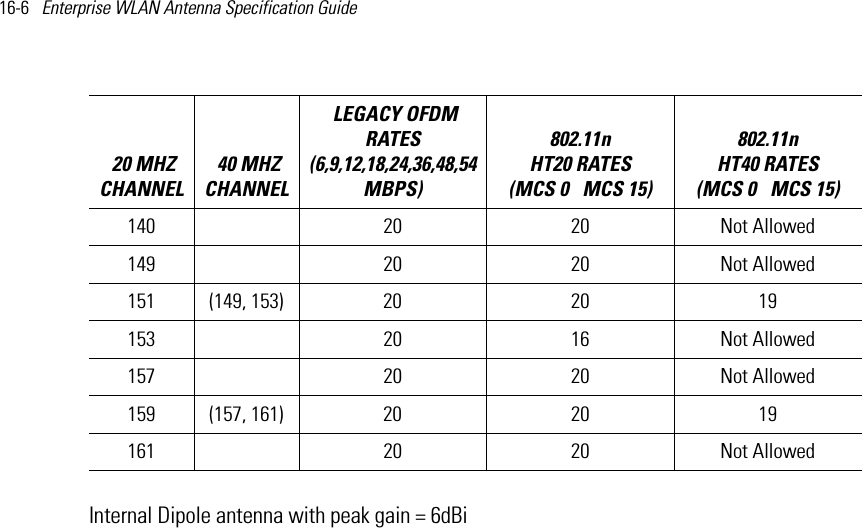
Antenna Installation Guide 050412

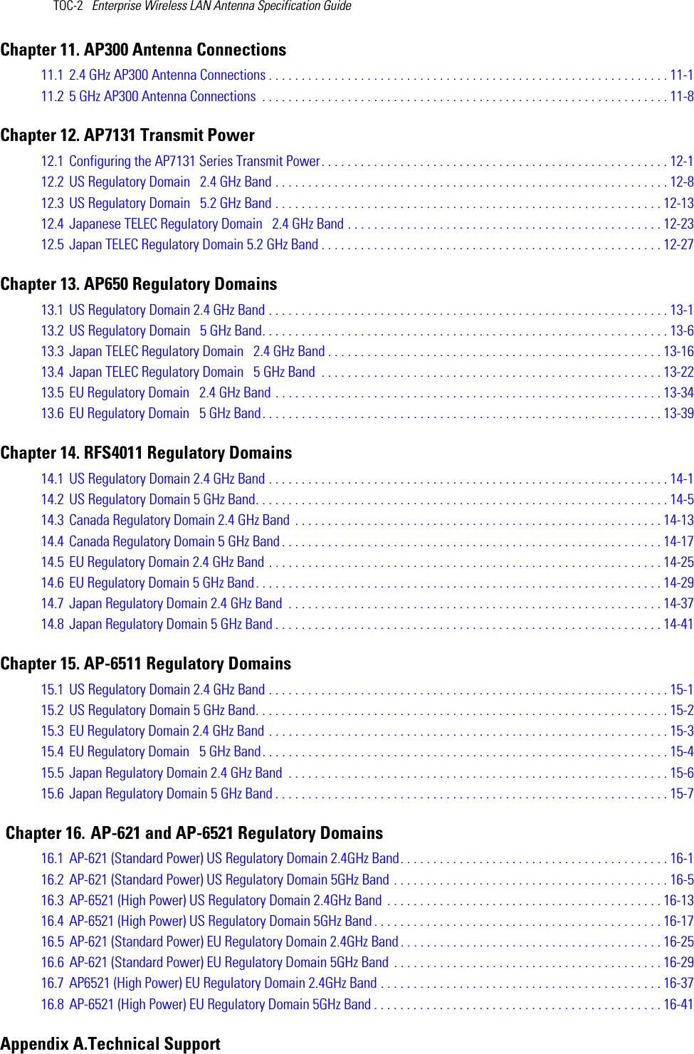
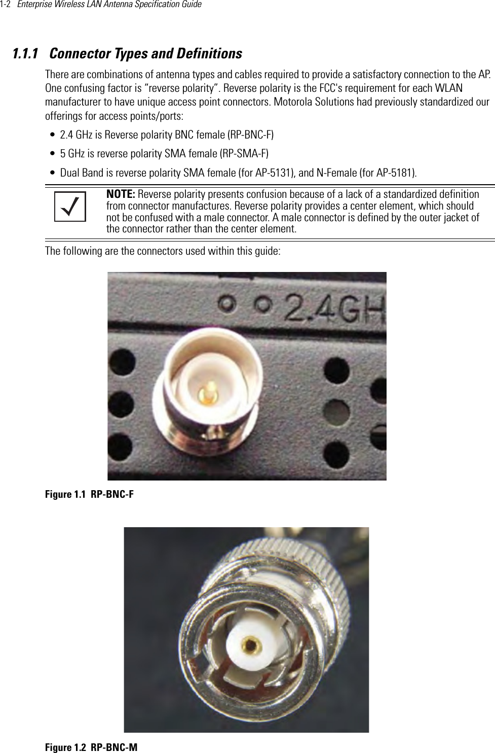
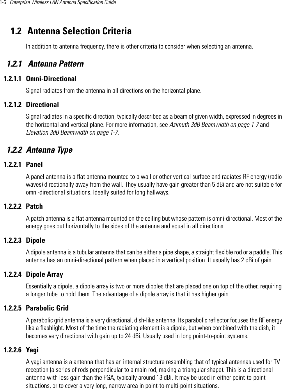
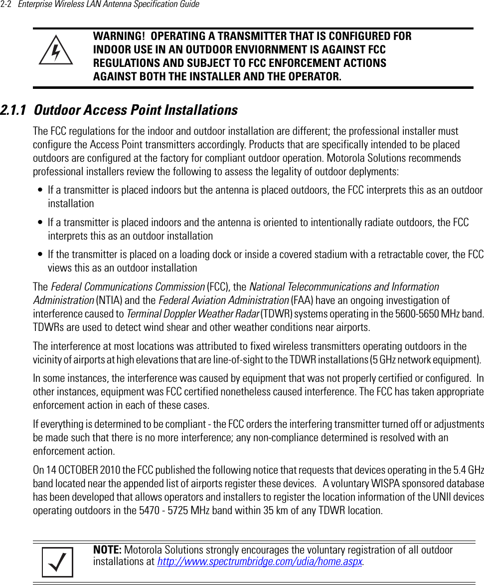
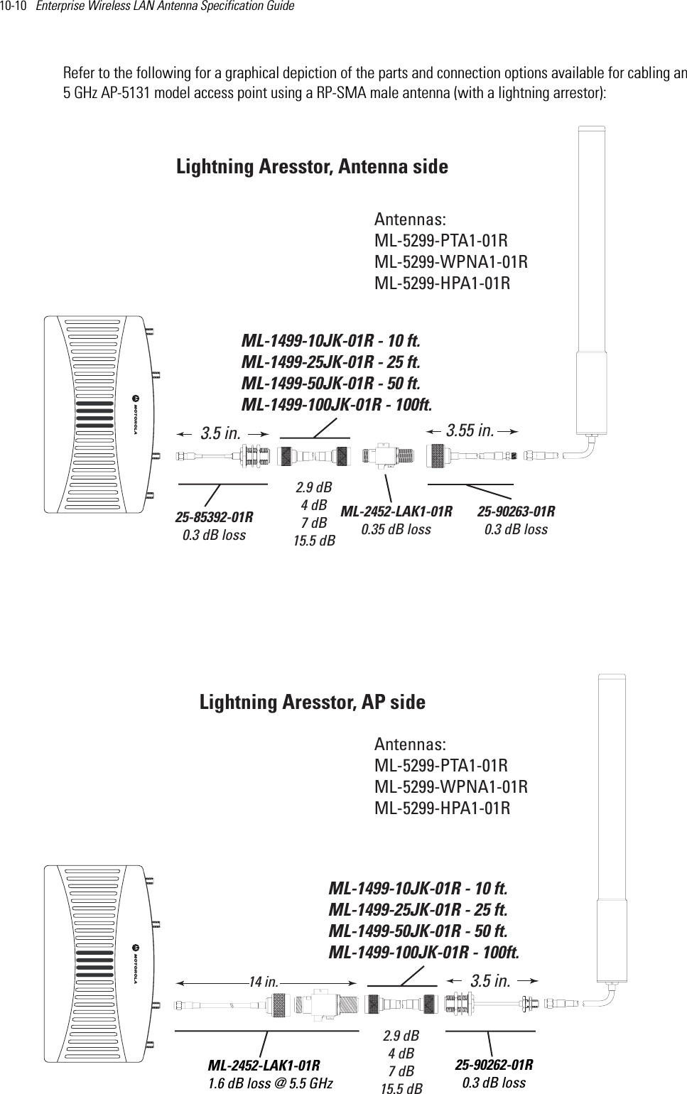
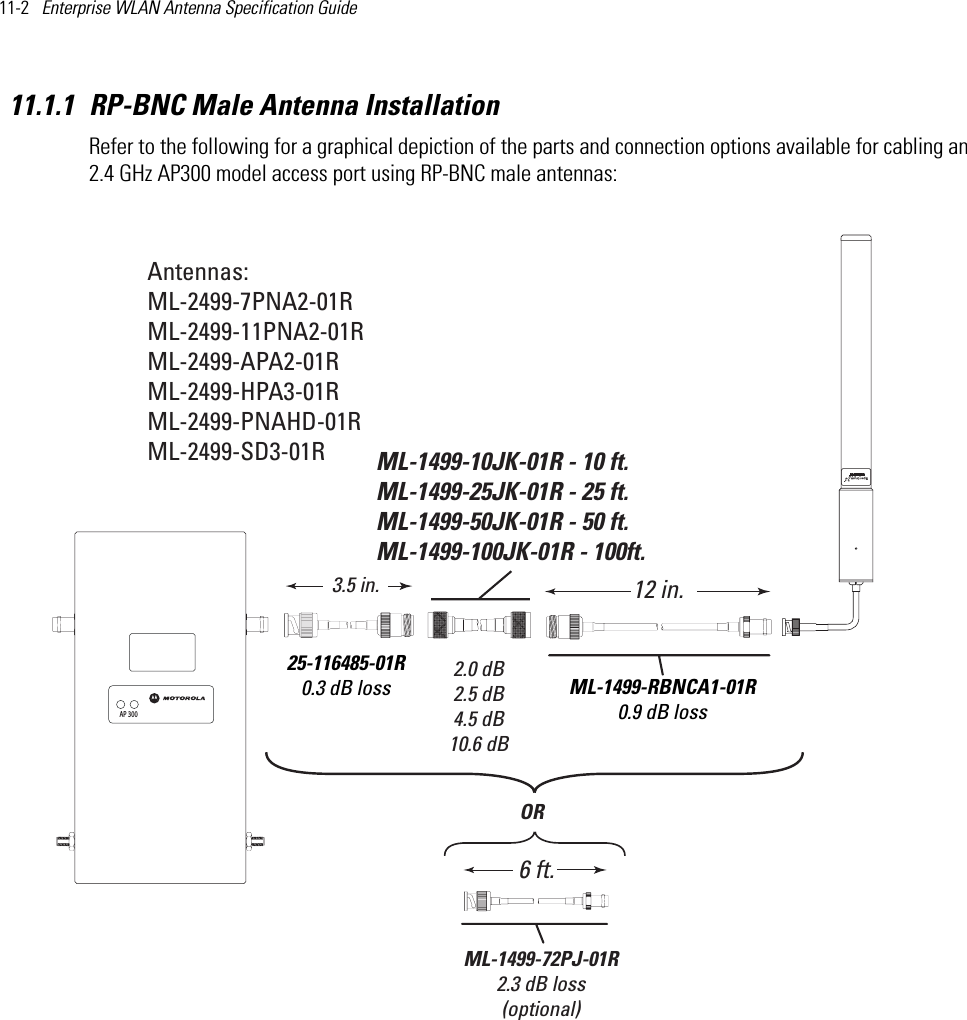
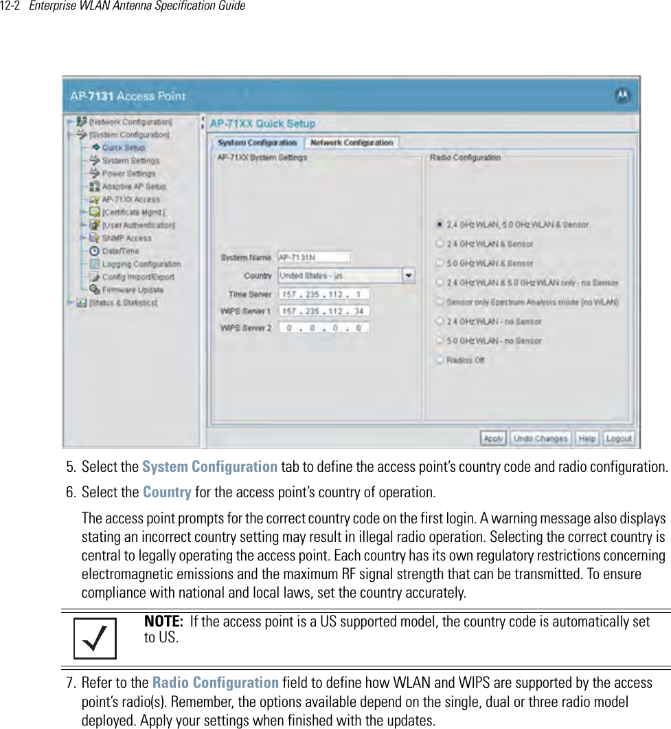
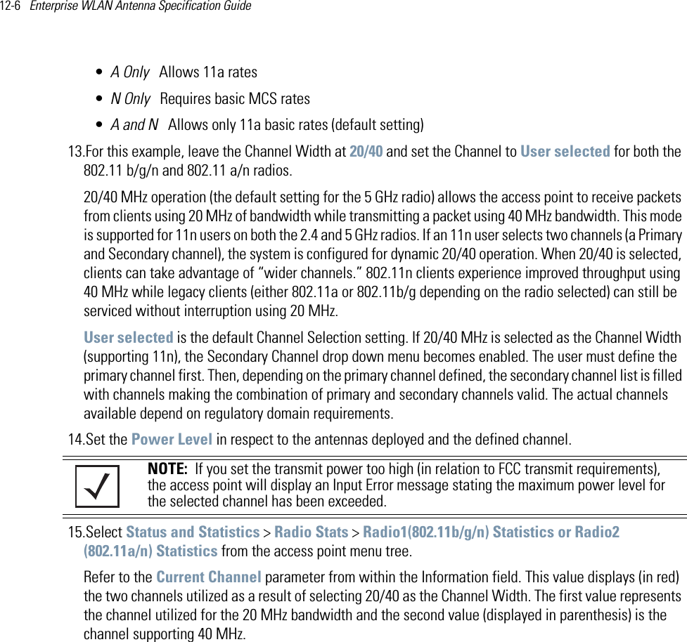
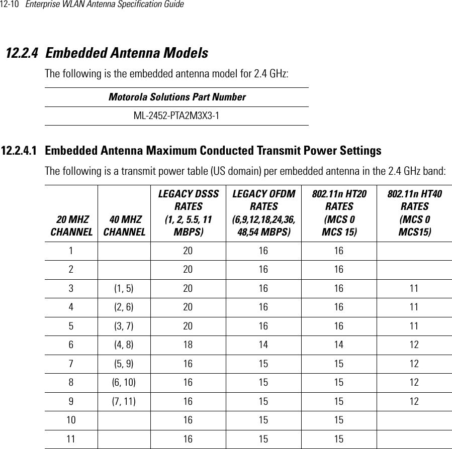
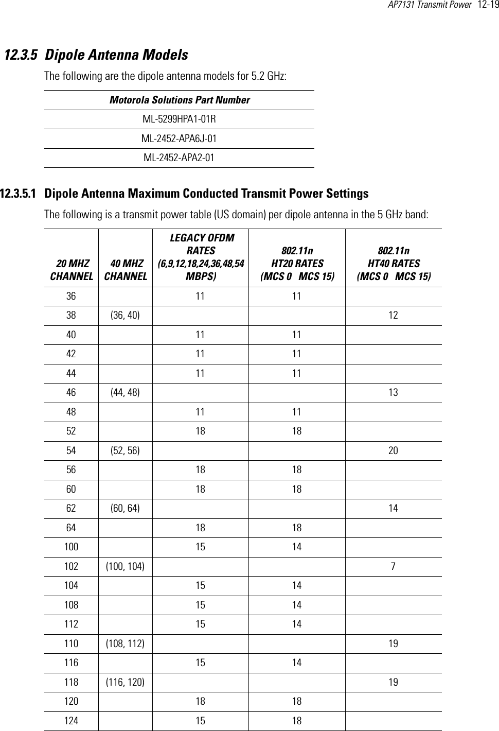
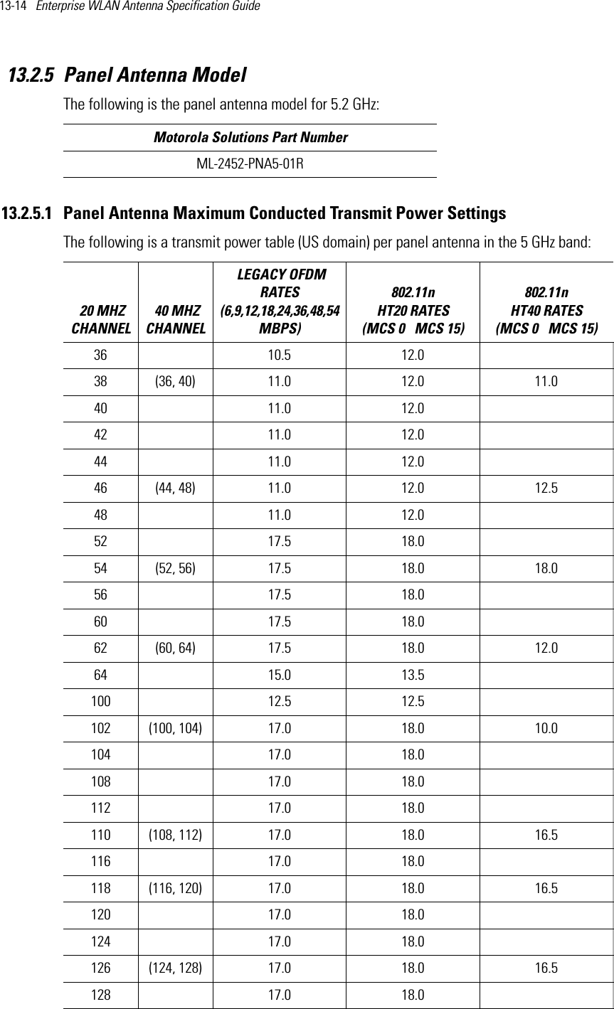
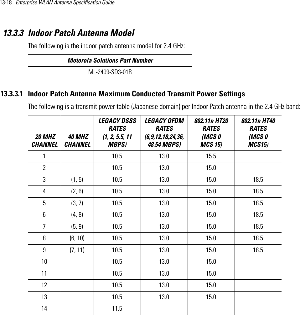
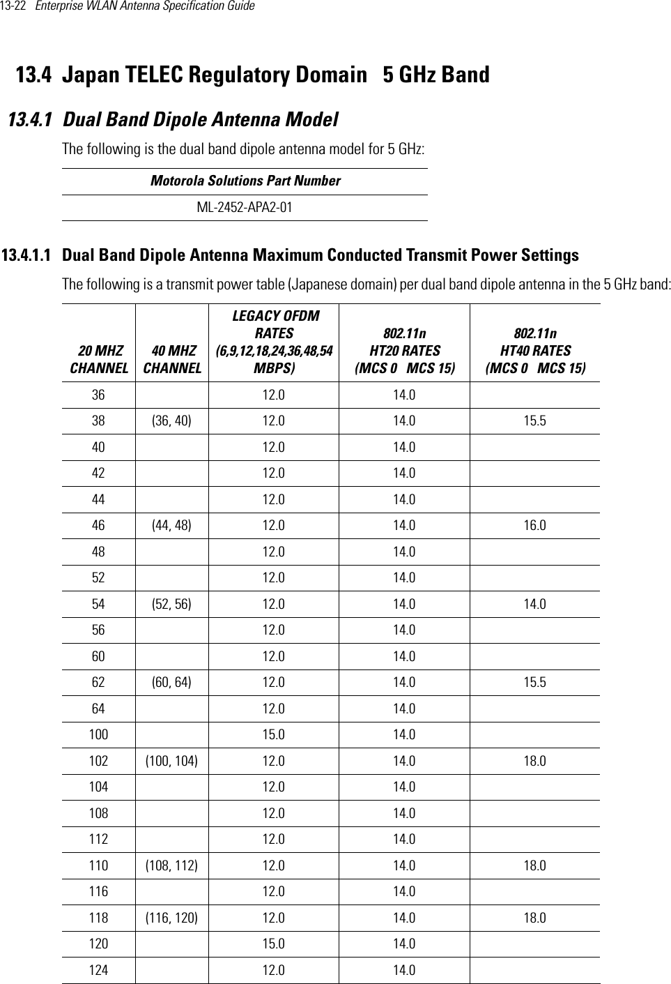
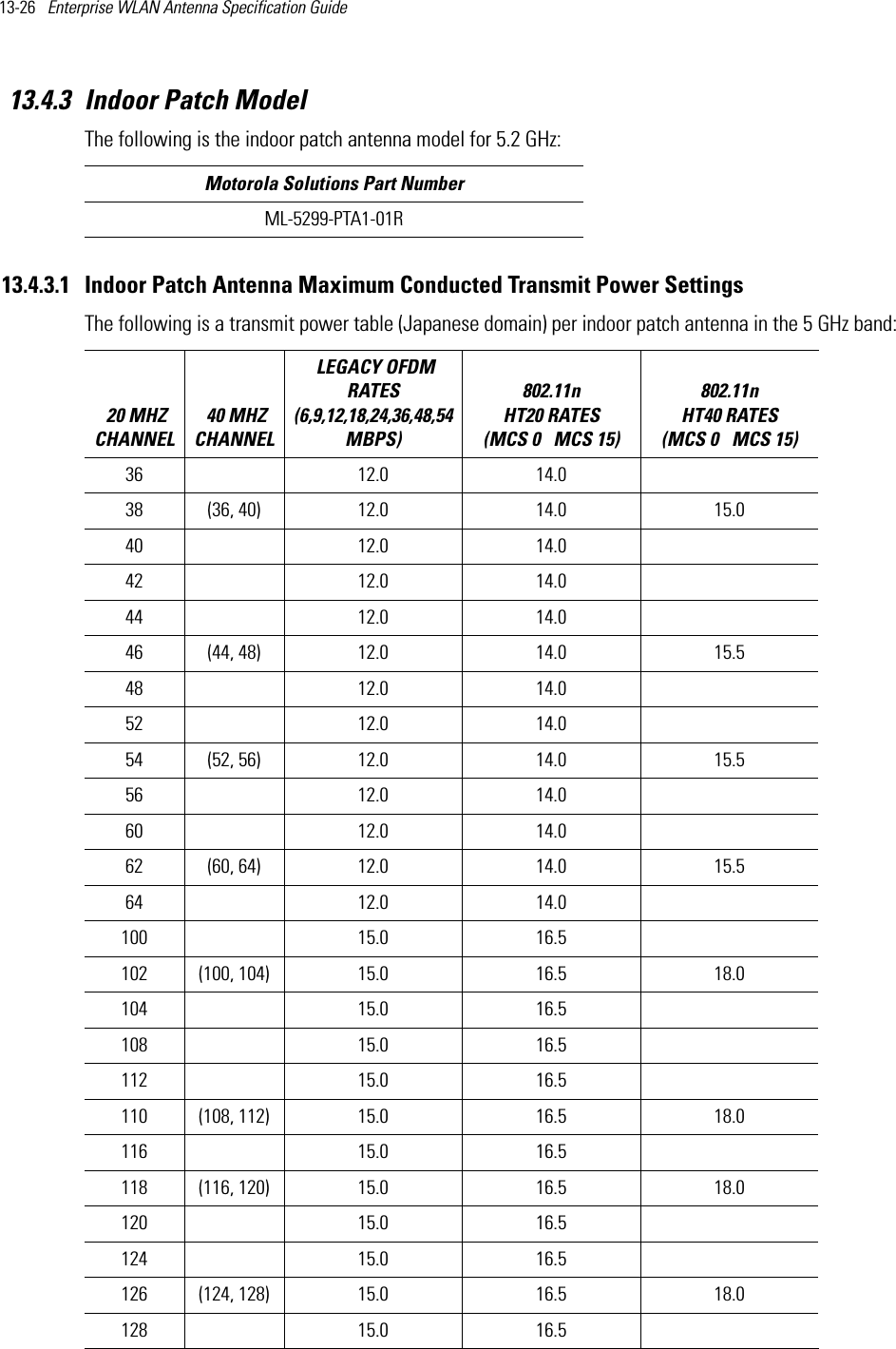
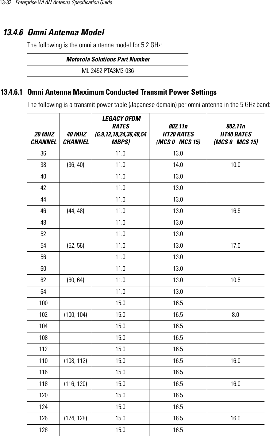
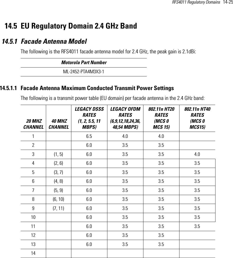
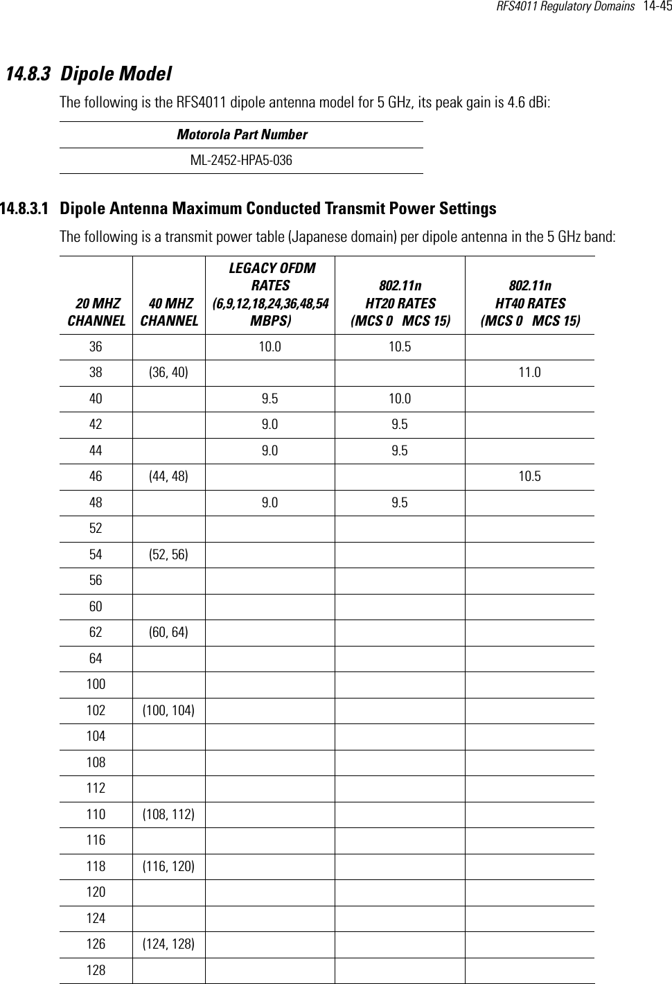
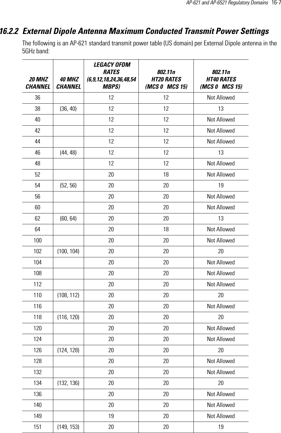
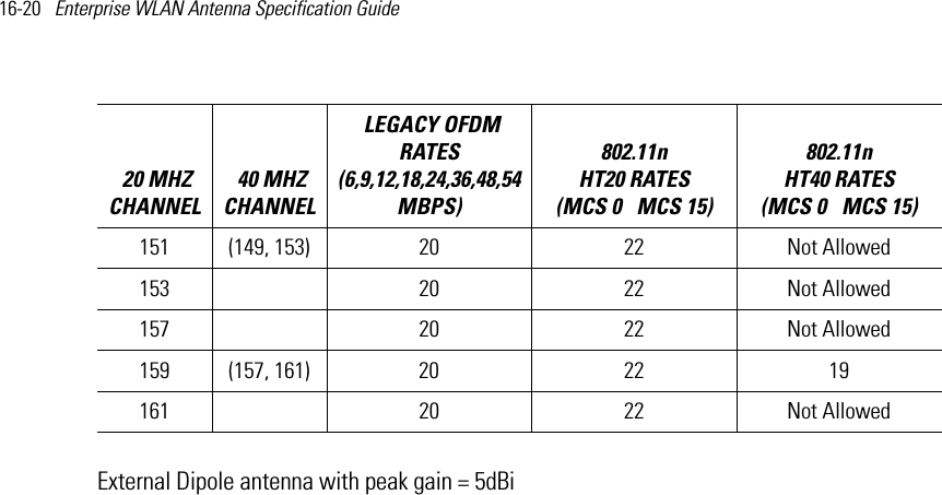
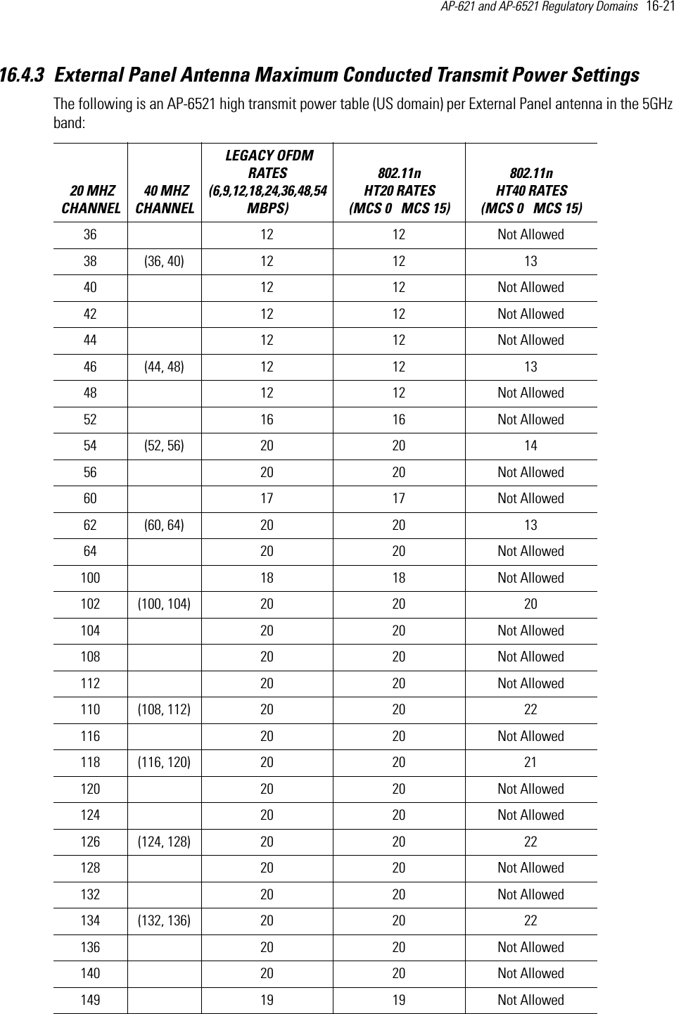
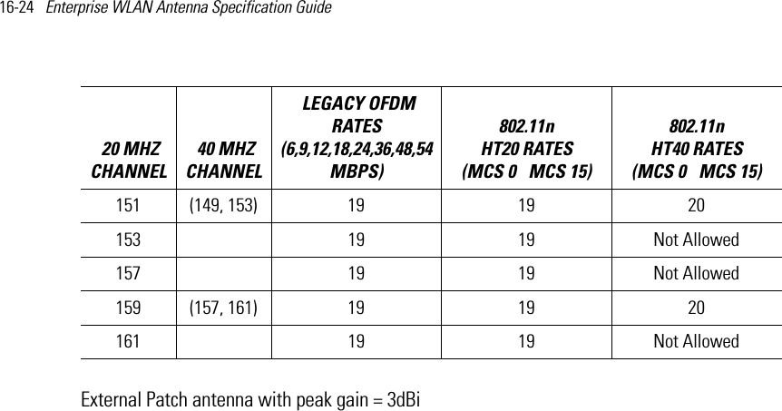
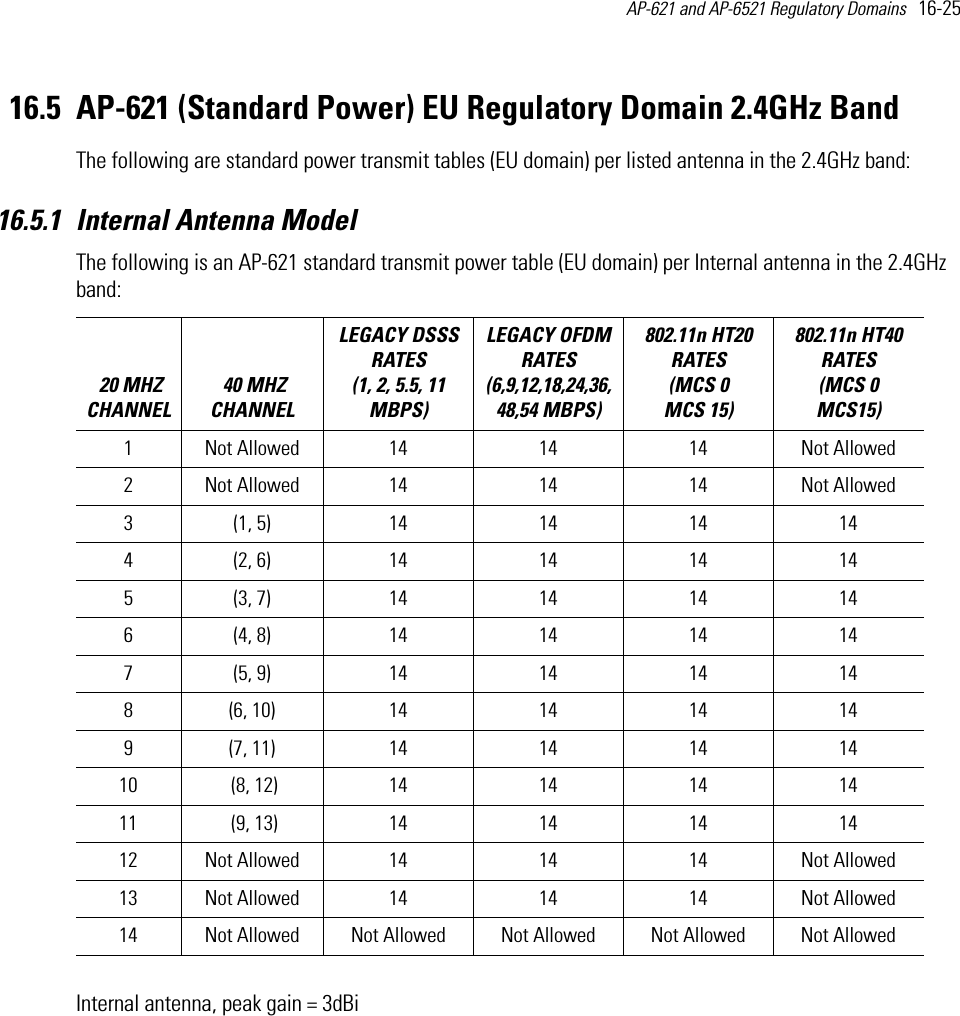
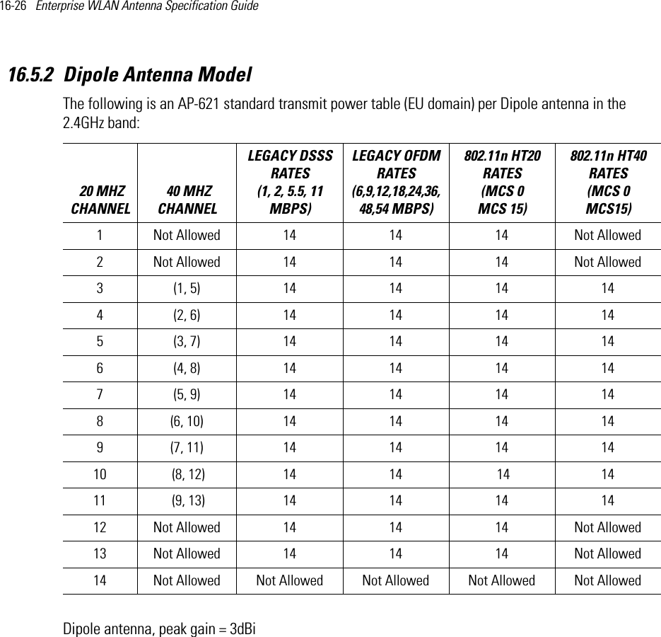
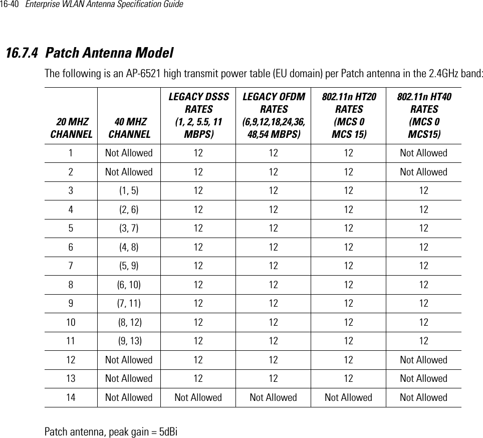
![2-4 Enterprise Wireless LAN Antenna Specification Guide • All applications for equipment authorization must clearly show compliance with all of the technical requirements under worst case parameters, under user or operator control, based on frame rates, listen/talk ratios and user data transfer conditions.All the devices subject to the DFS requirements must be submitted to the Commission’s Laboratory Division for pre-grant testing and equipment authorization.8 The applicant must ensure that all equipment authorization applications subject to this interim procedure include appropriate attestations that the device has no option to change the DFS parameters and that transmissions are disabled at least in the 5600 – 5650 MHz band. The application must include the user’s manual with the appropriate installation and operations requirements for the installers and operators.We are continuing to evaluate additional measures that may need to be taken to further ensure against interference caused by 5 GHz outdoor wireless systems located near airports. While manufacturers have an obligation to ensure that their equipment complies with FCC rules, and must take steps to ensure their devices are unlikely to cause harmful interference, Section 15.5 of the Commission’s rules also places an obligation on users of devices to avoid causing interference and to correct any interference that may occur. We encourage the manufacturers to include information for the users, including the operators and installers, to ensure that they understand that it is incumbent on them to cooperate with manufacturers to implement any changes necessary to facilitate compliance.5 Devices may be optionally designed not to transmit on channels which overlap 5570 – 5680 MHz instead of requiring installers to perform site-by-site adjustments. In that case it is still required that the devices should be installed professionally and the procedures for registering the device in the industry database should be included in the Users Manual.6 A voluntary WISPA sponsored database has been developed that allows operators and installers to register the location information of the UNII devices operating outdoors in the 5470 – 5725 MHz band within 35 km of any TDWR location (see http://www.spectrumbridge.com/udia/home.aspx). This database may be used by government agencies in order to expedite resolution of any interference to TDWRs.7 For example, device software must not have any country code options or software configuration settings which allow an end user to modify the DFS operation or impact the performance of DFS. See KDB 594280.8 The TCBs are not permitted to approve transmitters with radar detection capabilities. See KDB 628591.9 The manufacturers may consider taking steps providing clear instructions to operators and installers of devices as to the need to comply with rules for use of the band, guidance on registration of devices and any other processes that are designed to avoid interference. They may use methods that include, but are not limited to, instructions in manuals, notification on product web pages and service bulletins issued for products in the field.TDWR Location Information*STATE CITY LONGITUDE LATITUDE FREQUENCY TERRAIN ELEVATION (MSL) [ft]ANTENNA HEIGHT ABOVE TERRAIN [ft]AZ PHOENIX W 112 09 46 N 33 25 14 5610 MHz 1024 64CO DENVER W 104 31 35 N 39 43 39 5615 MHz 5643 64FL FT LAUDERDALE W 080 20 39 N 26 08 36 5645 MHz 7 113FL MIAMI W 080 29 28 N 25 45 27 5605 MHz 10 113FL ORLANDO W 081 19 33 N 28 20 37 5640 MHz 72 97FL TAMPA W 082 31 04 N 27 51 35 5620 MHz 14 80FL WEST PALM BEACHW 080 16 23 N 26 41 17 5615 MHz 20 113](https://usermanual.wiki/Zebra-Technologies/AP6.Antenna-Installation-Guide-050412/User-Guide-1702053-Page-18.png)
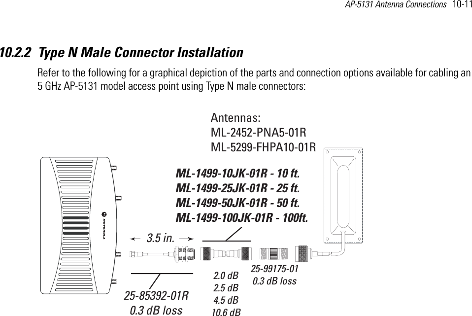
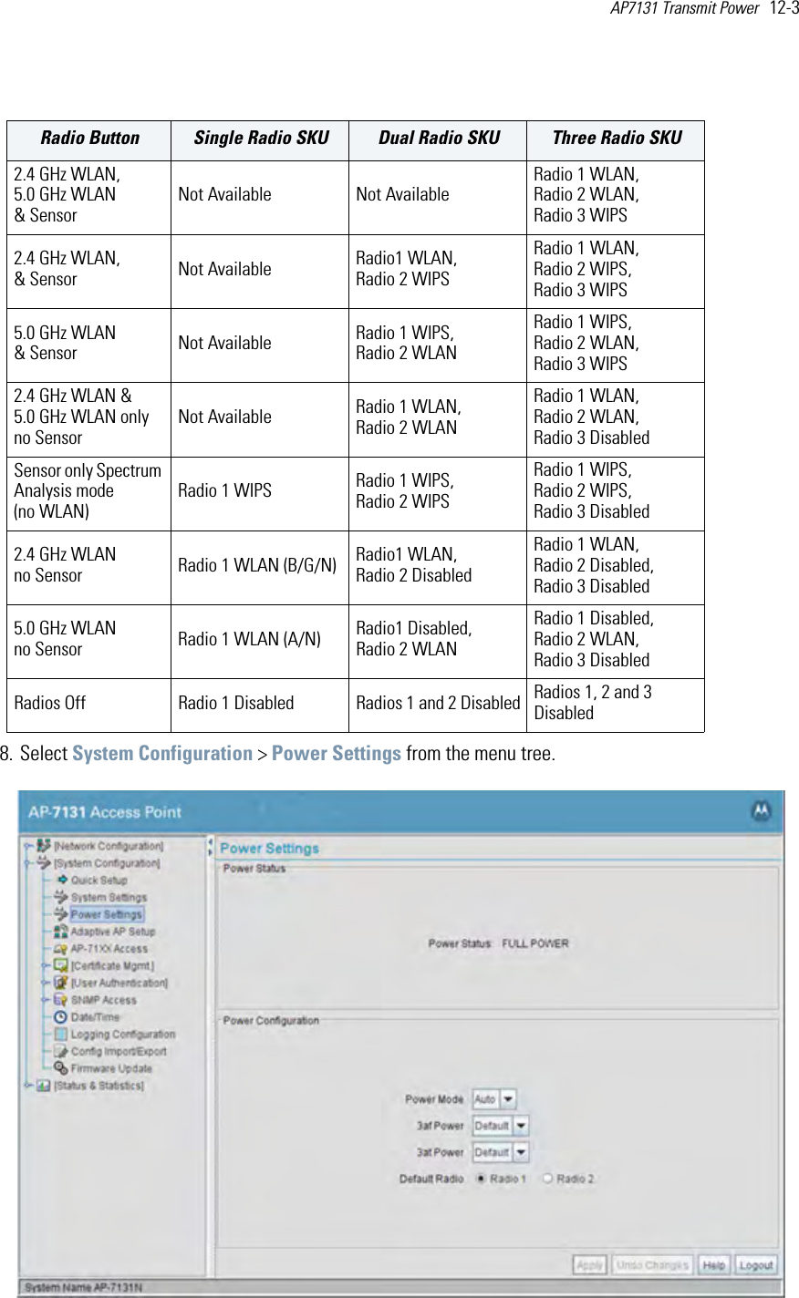
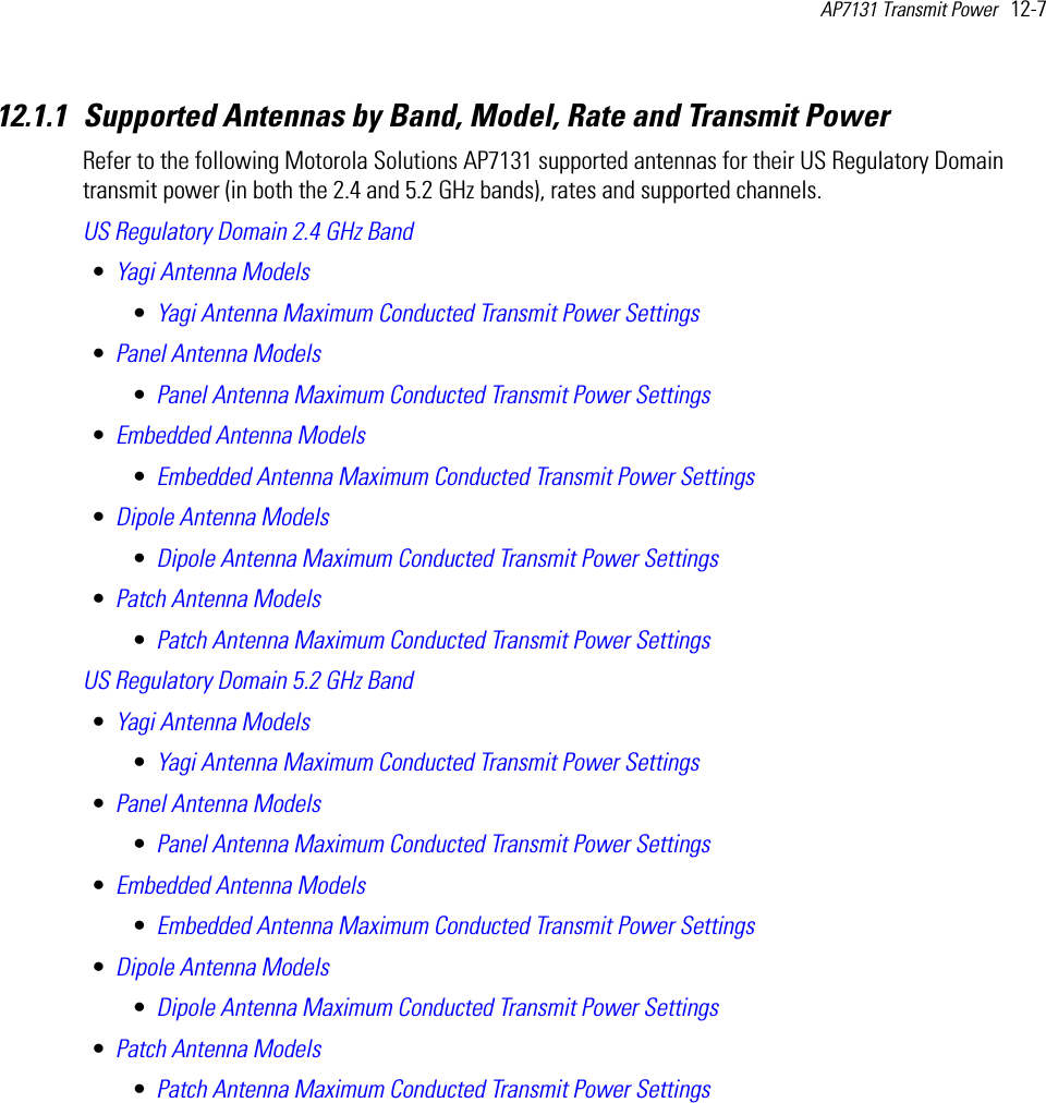
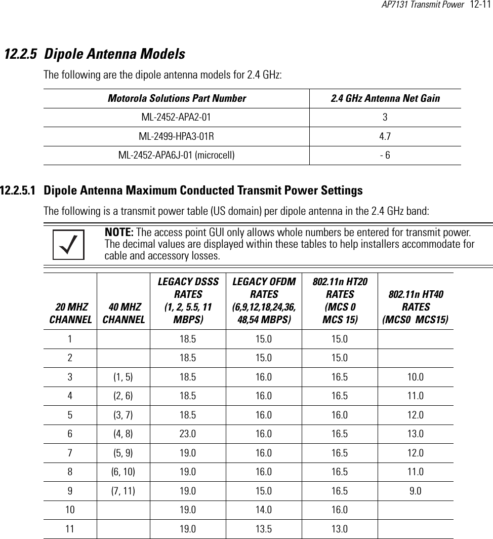
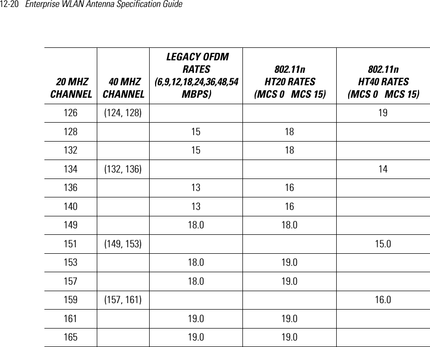
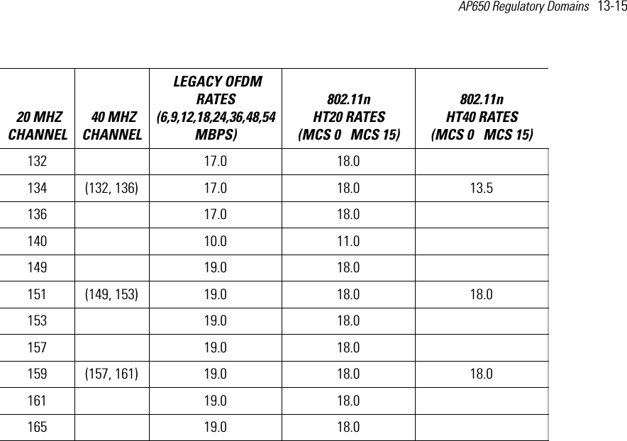
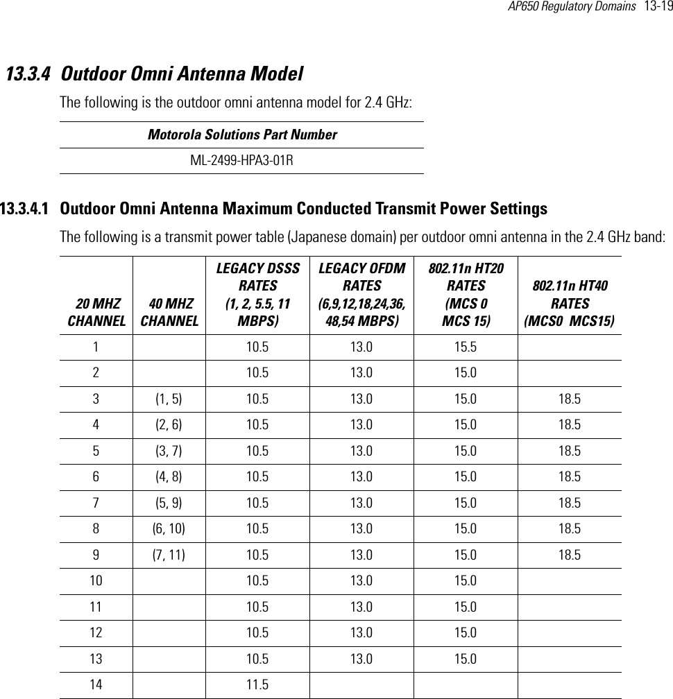
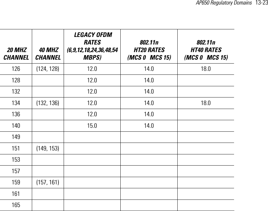
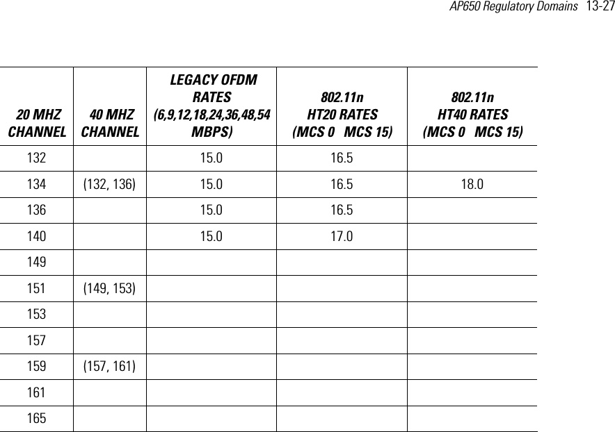
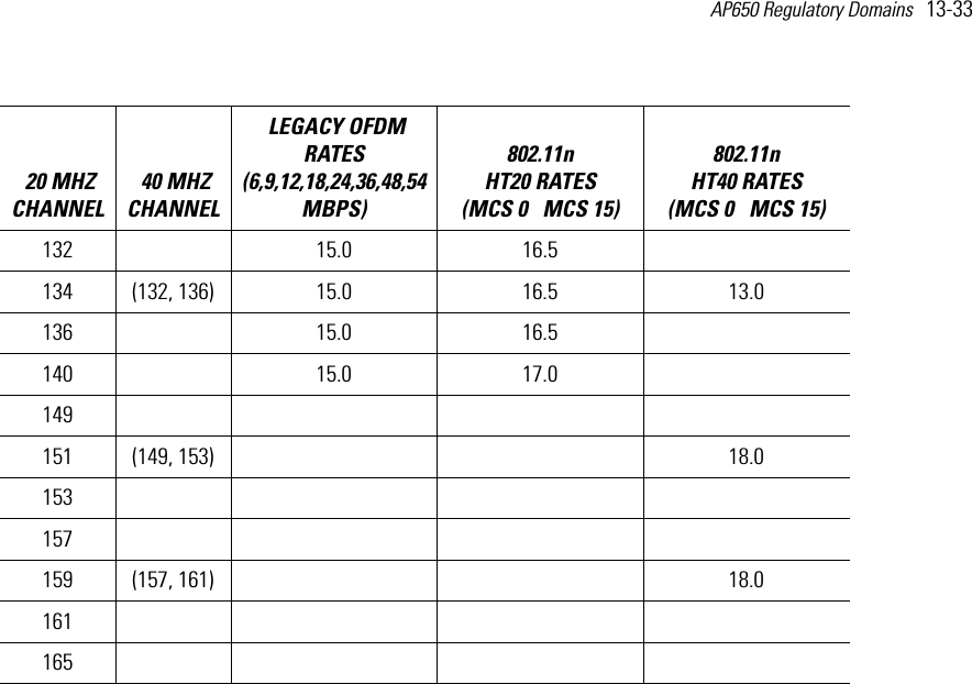
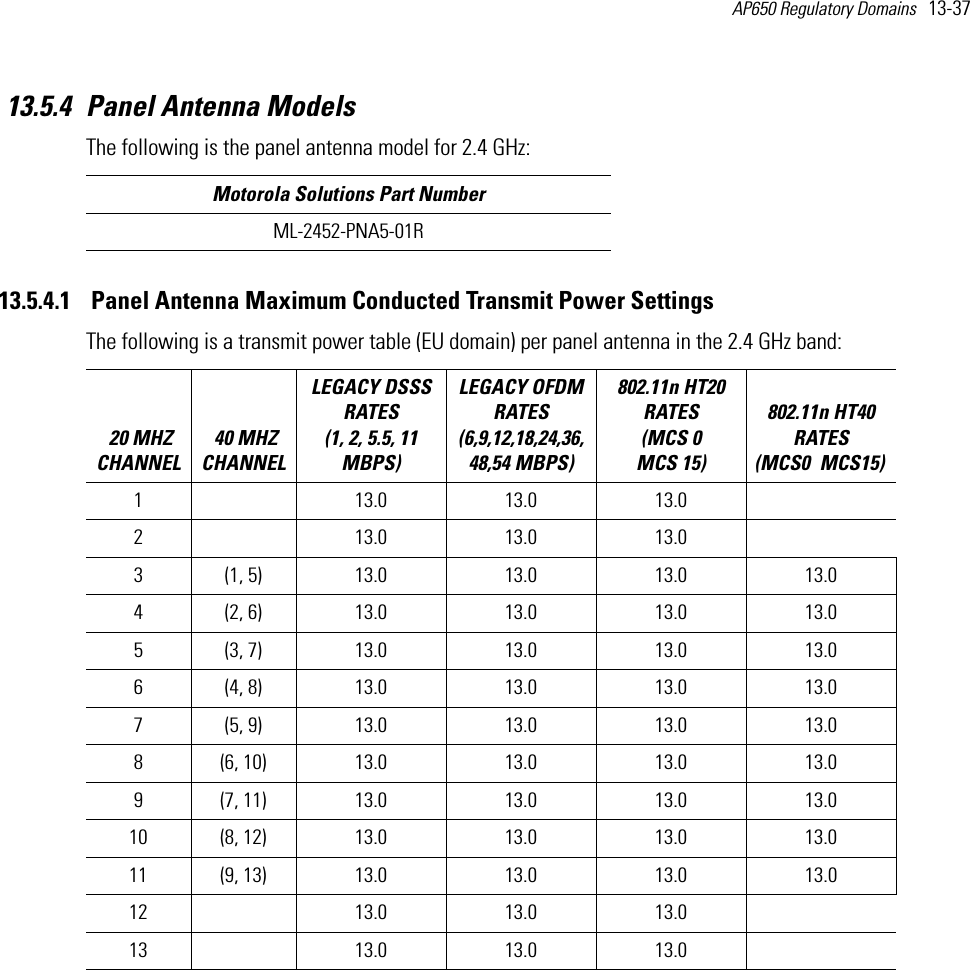
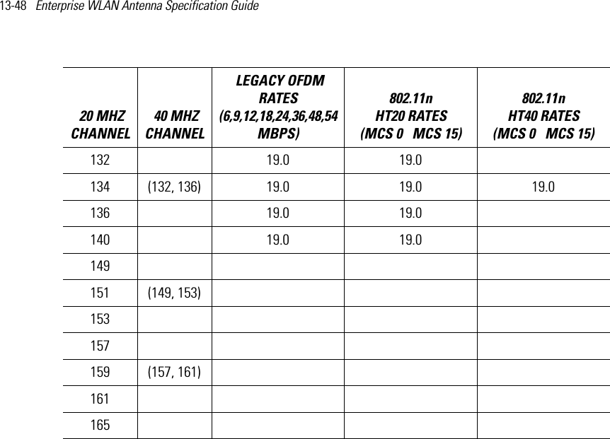
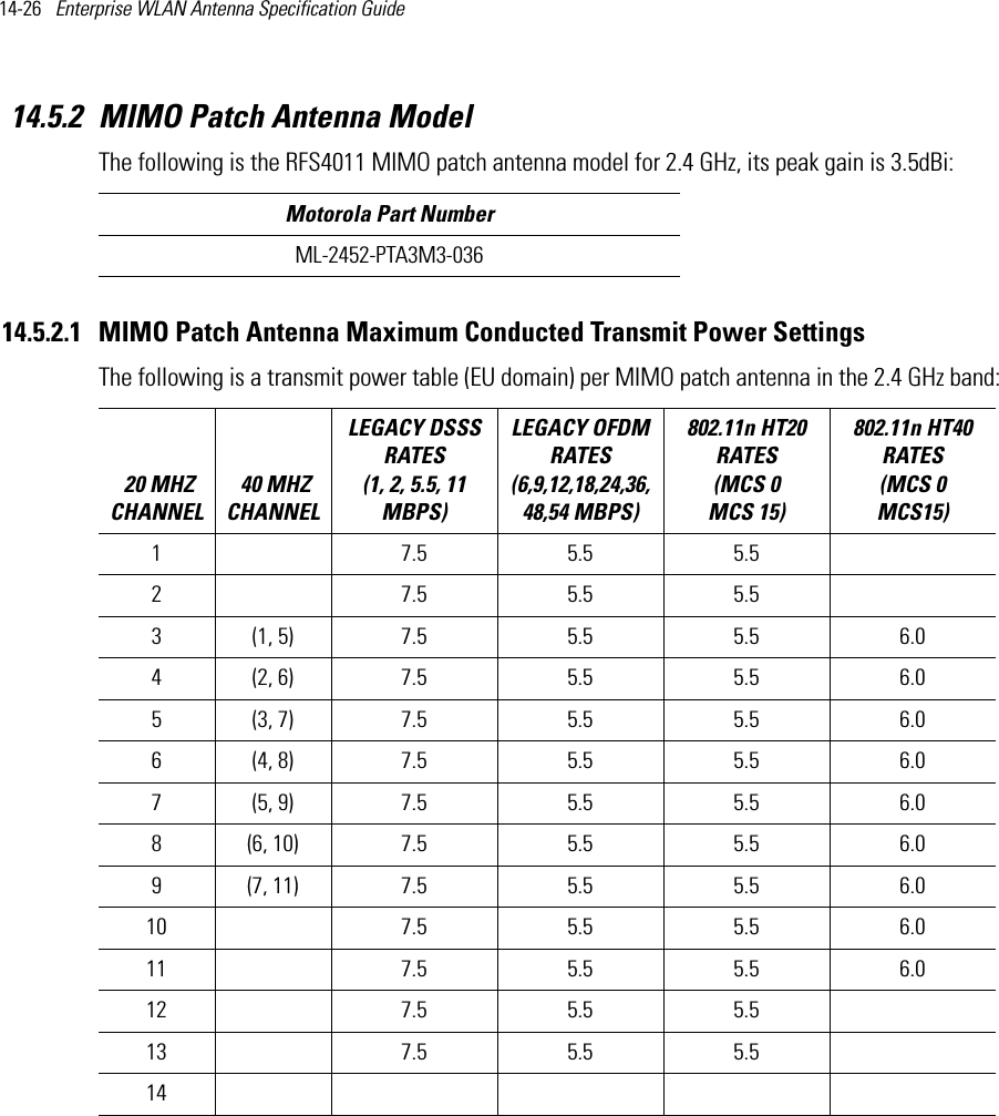
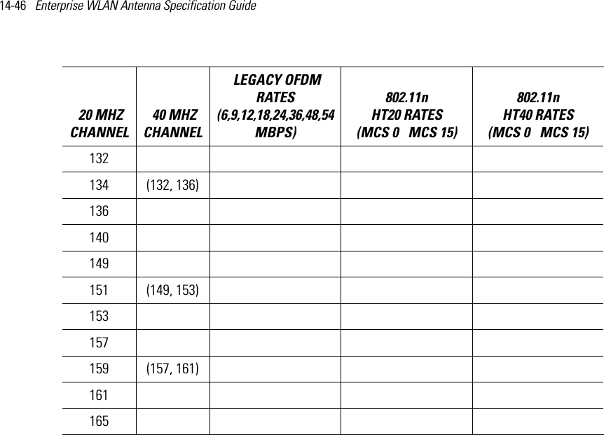
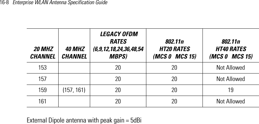
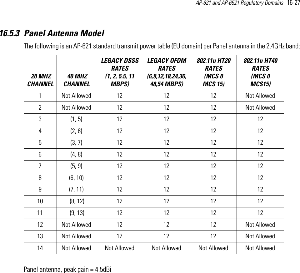
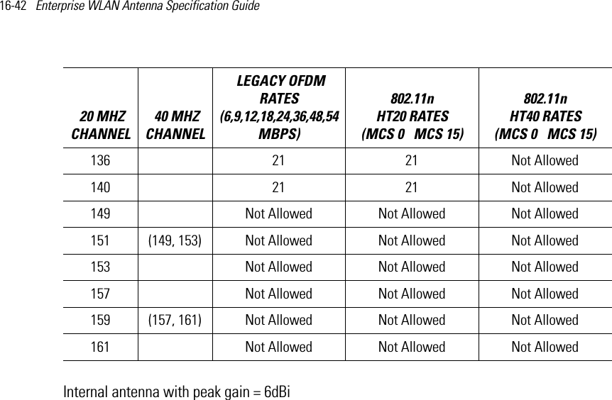
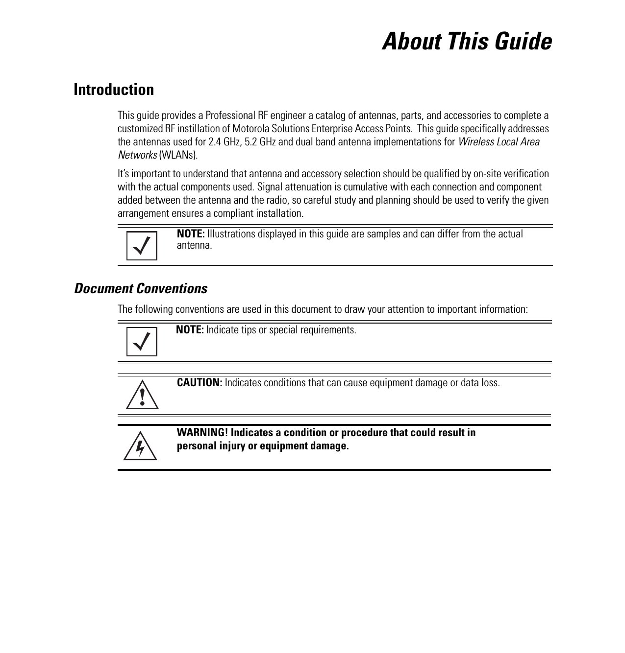
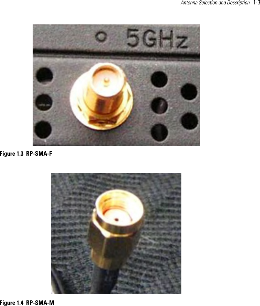
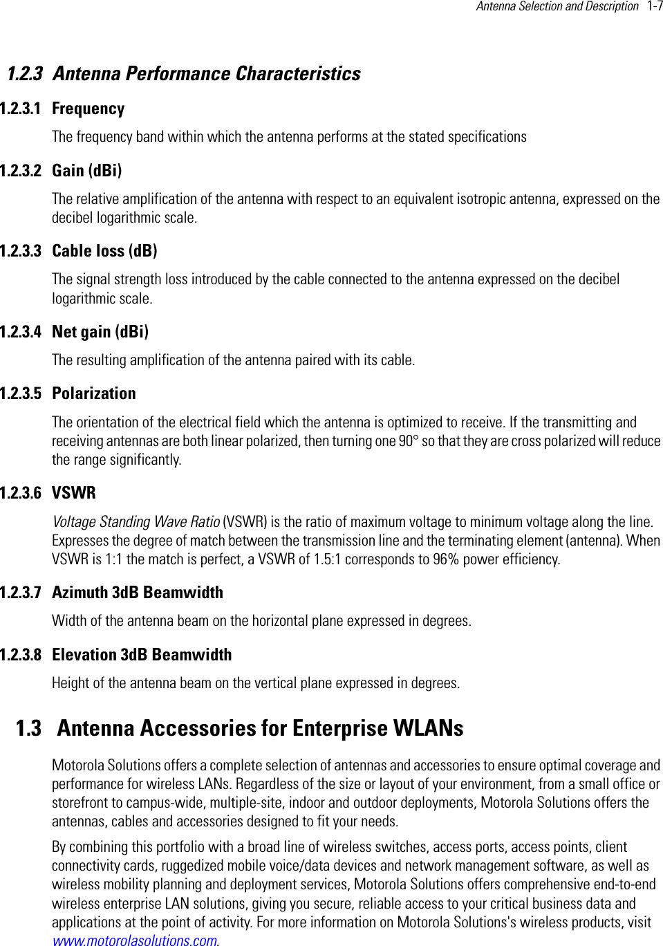
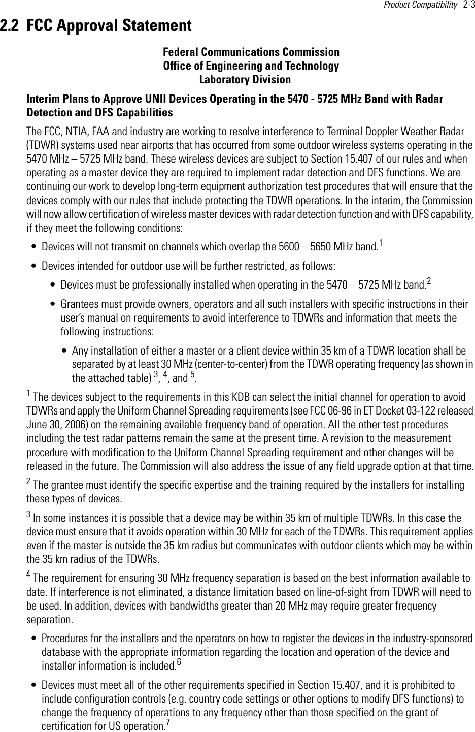
![Product Compatibility 2-5 GS ATLANTA W 084 15 44 N 33 38 48 5615 MHz 962 113IL MCCOOK W 087 51 31 N 41 47 50 5615 MHz 646 97IL CRESTWOOD W 087 43 47 N 41 39 05 5645 MHz 663 113IN INDIANAPOLIS W 086 26 08 N 39 38 14 5605 MHz 751 97KS WICHITA W 097 26 13 N 37 30 26 5603 MHz 1270 80KY COVINGTON CINNCINNATIW 084 34 48 N 38 53 53 5610 MHz 942 97KY LOUISVILLE W 085 36 38 N 38 02 45 5646 MHz 617 113LA NEW ORLEANS W 090 24 11 N 30 01 18 5645 MHz 2 97MA BOSTON W 070 56 01 N 42 09 30 5610 MHz 151 113MD BRANYWINE W 076 50 42 N 38 41 43 5635 MHz 233 113MD BENFIELD W 076 37 48 N 39 05 23 5645 MHz 184 113MD CLINTON W 076 57 43 N 38 45 32 5615 MHz 249 97MI DETROIT W 083 30 54 N 42 06 40 5615 MHz 656 113MN MINNEAPOLIS W 092 55 58 N 44 52 17 5610 MHz 1040 80MO KANSAS CITY W 094 44 31 N 39 29 55 5605 MHz 1040 64MO SAINT LOUIS W 090 29 21 N 38 48 20 5610 MHz 551 97MS DESOTO COUNTYW 089 59 33 N 34 53 45 5610 MHz 371 113NC CHARLOTTE W 080 53 06 N 35 20 14 5608 MHz 757 113NC RALEIGH DURHAMW 078 41 50 N 36 00 07 5647 MHz 400 113NJ WOODBRIDGE W 074 16 13 N 40 35 37 5620 MHz 19 113NJ PENNSAUKEN W 075 04 12 N 39 56 57 5610 MHz 39 113NV LAS VEGAS W 115 00 26 N 36 08 37 5645 MHz 1995 64NY FLOYD BENNETT FIELDW 073 52 49 N 40 35 20 5647 MHz 8 97OH DAYTON W 084 07 23 N 40 01 19 5640 MHz 922 97OH CLEVELAND W 082 00 28 N 41 17 23 5645 MHz 817 113OH COLUMBUS W 082 42 55 N 40 00 20 5605 MHz 1037 113OK AERO. CTR TDWR #1W 097 37 31 N 35 24 19 5610 MHz 1285 80STATE CITY LONGITUDE LATITUDE FREQUENCY TERRAIN ELEVATION (MSL) [ft]ANTENNA HEIGHT ABOVE TERRAIN [ft]](https://usermanual.wiki/Zebra-Technologies/AP6.Antenna-Installation-Guide-050412/User-Guide-1702053-Page-19.png)
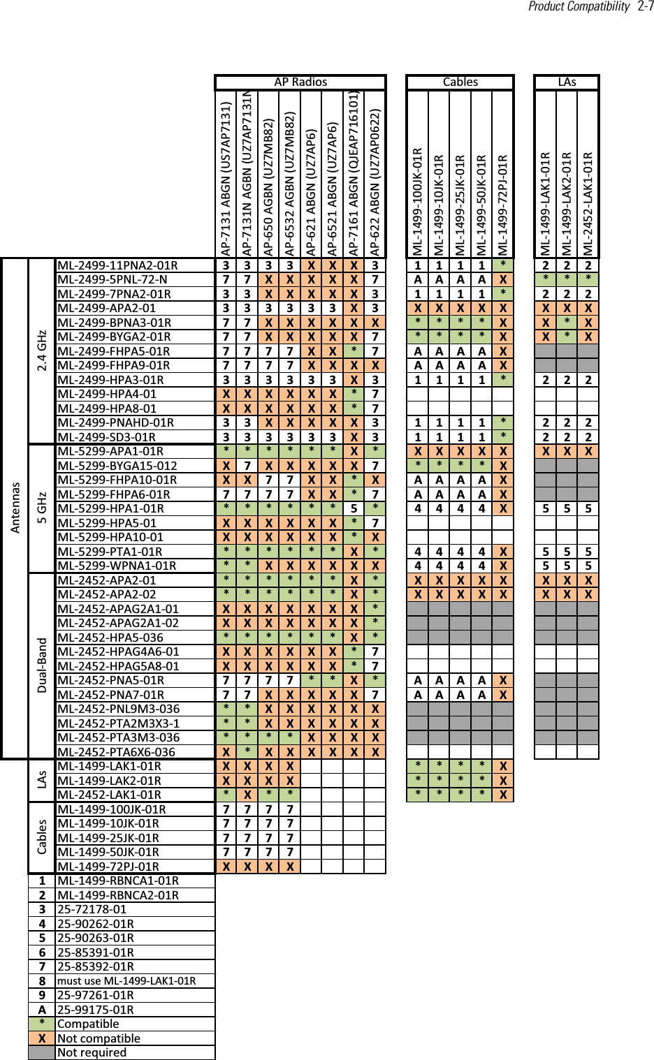
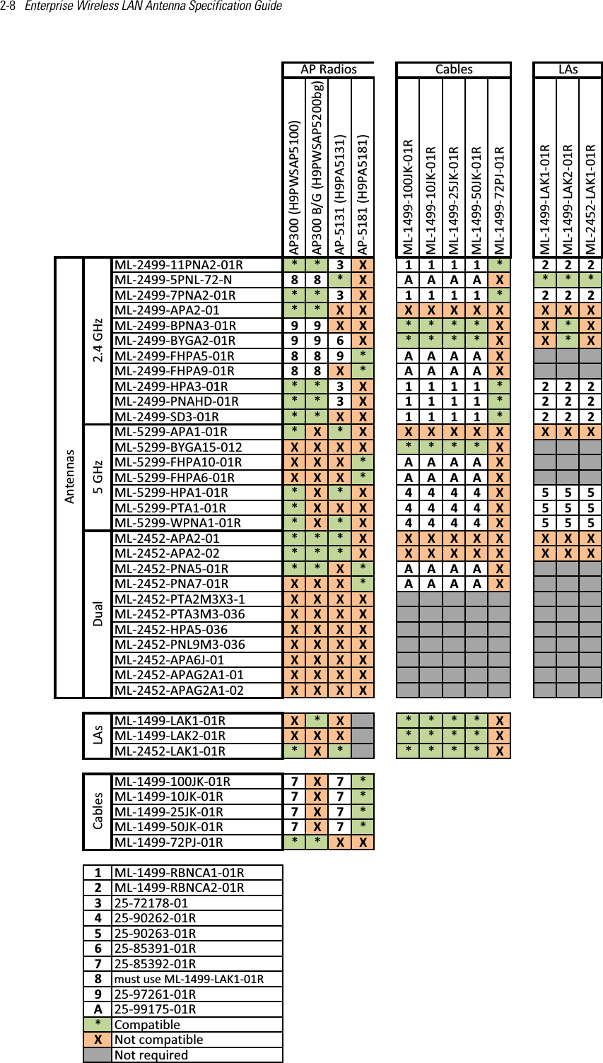
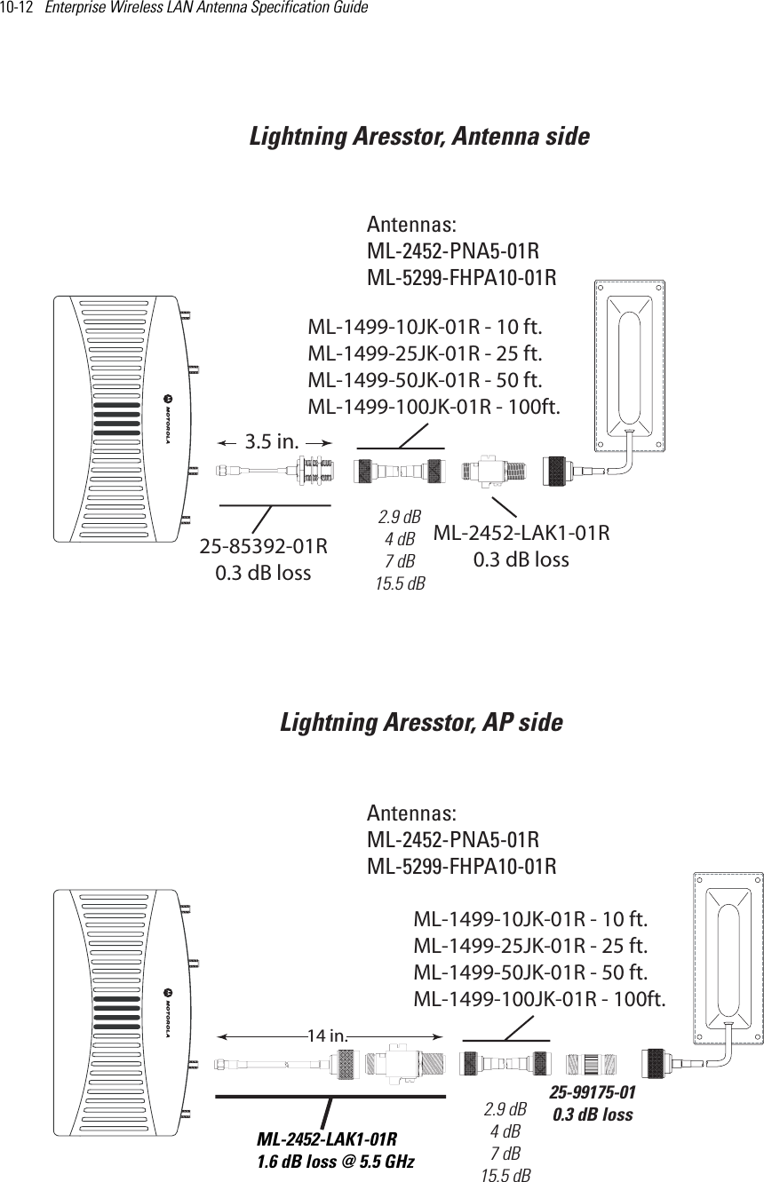
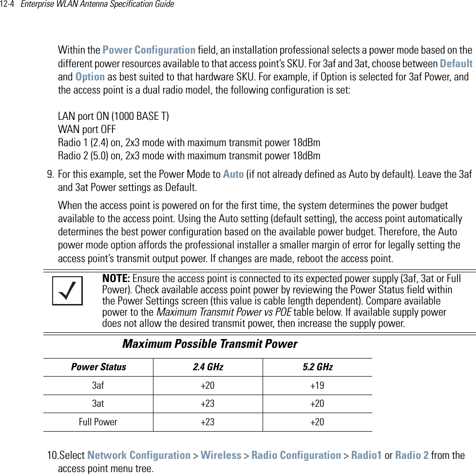
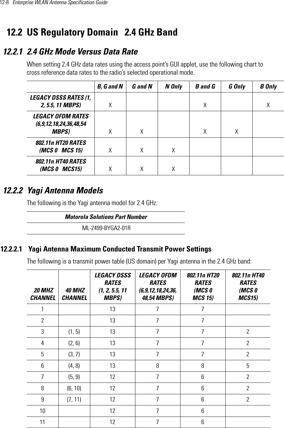
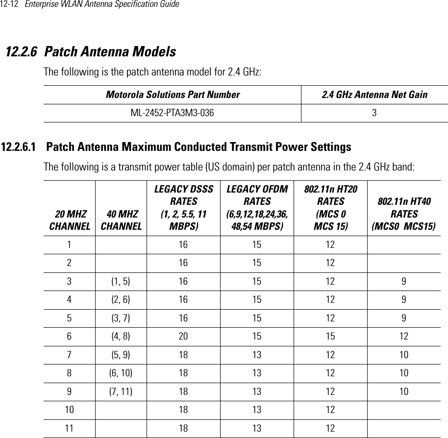
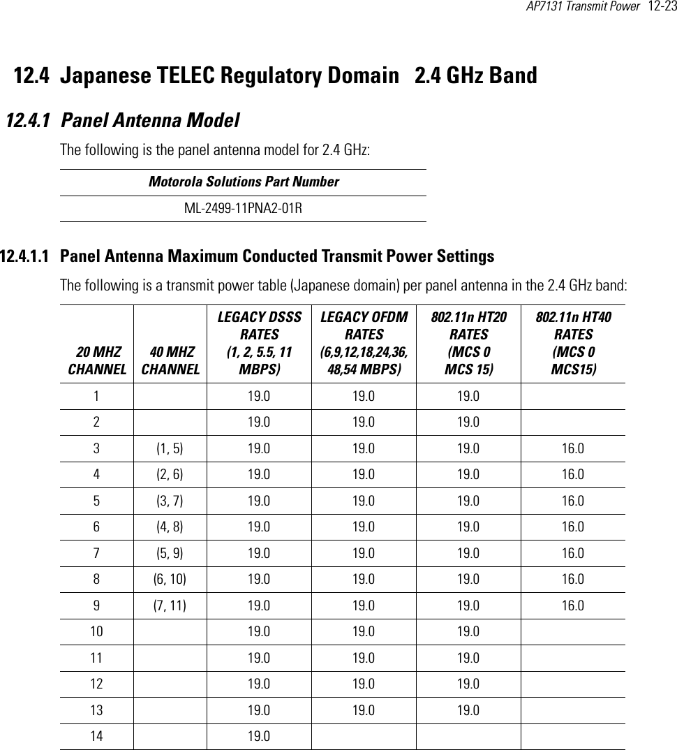
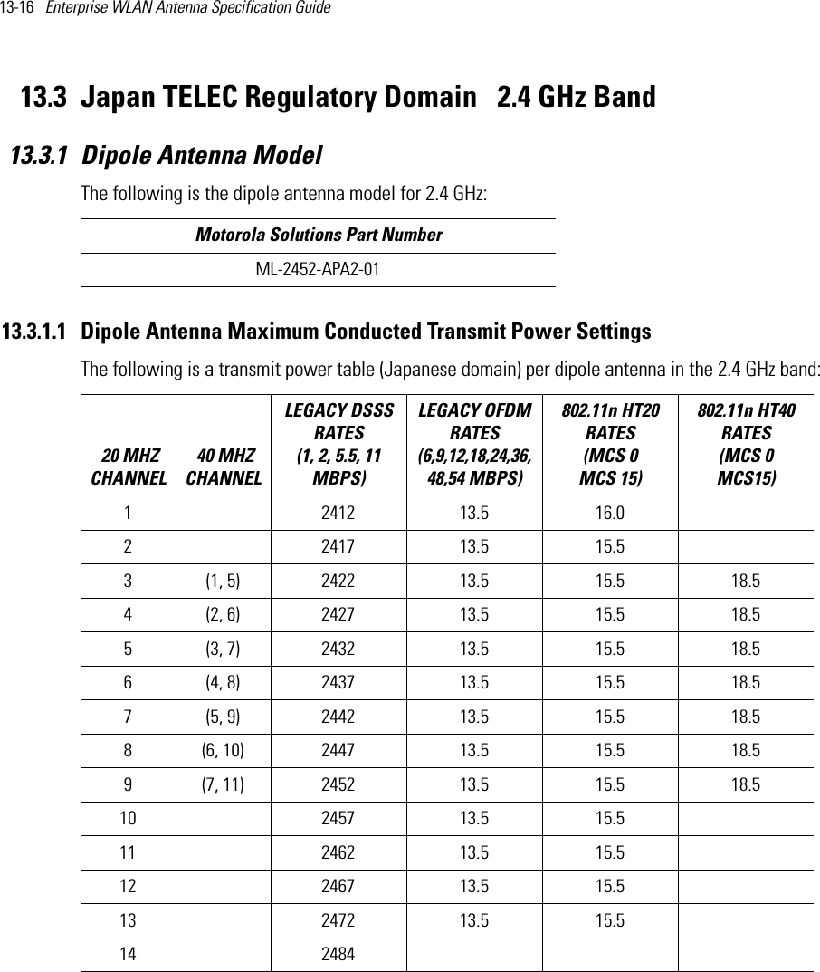
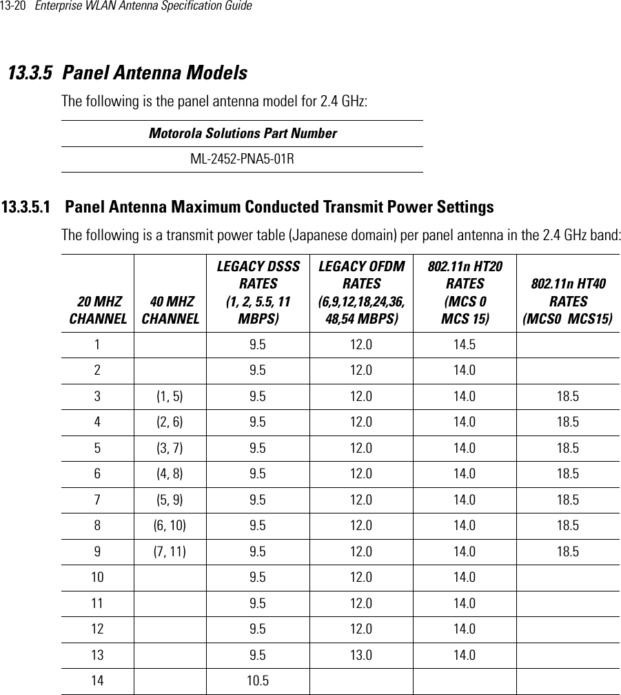
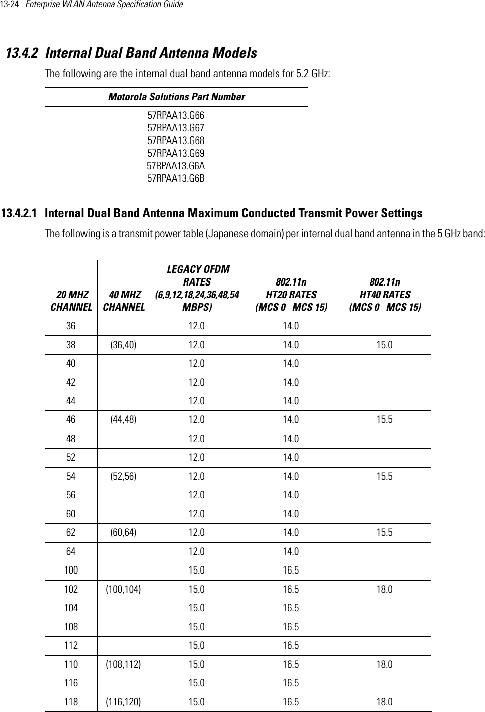
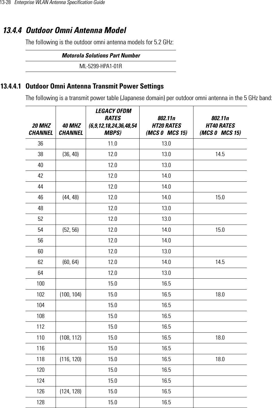
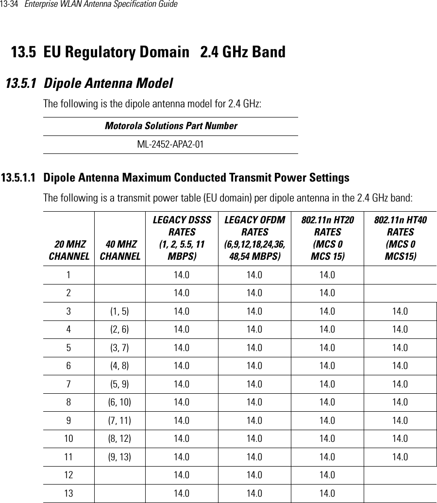
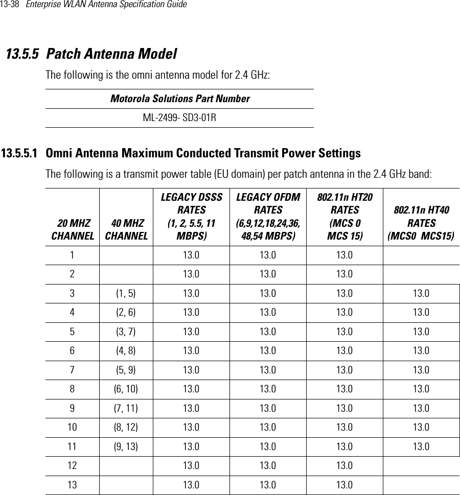
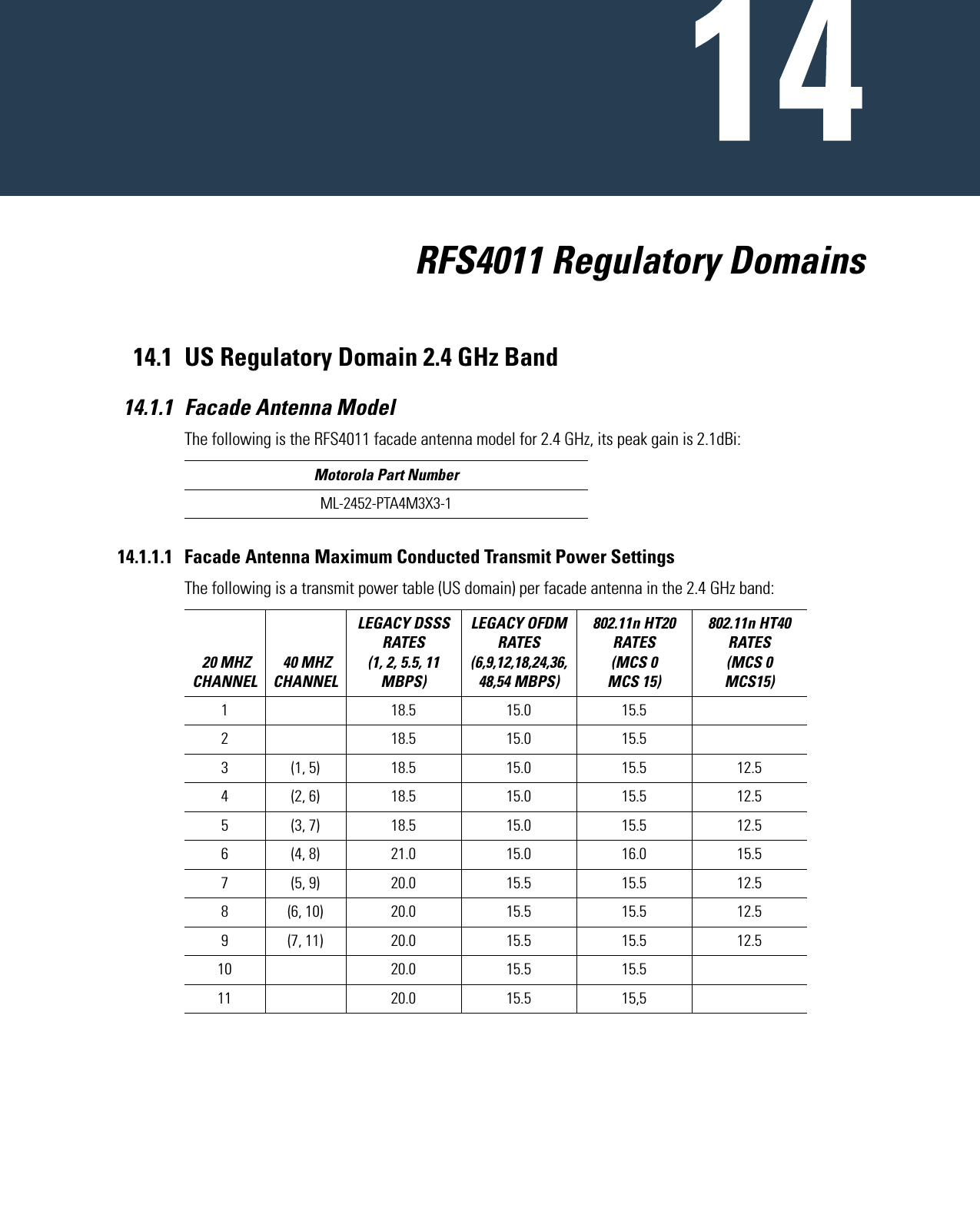
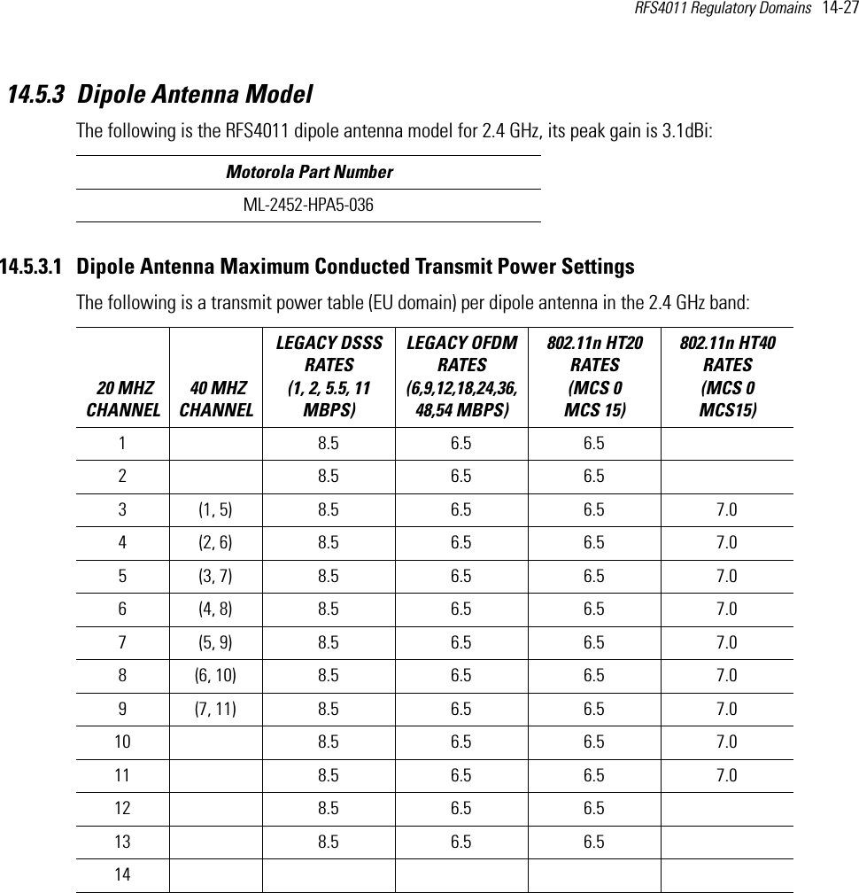
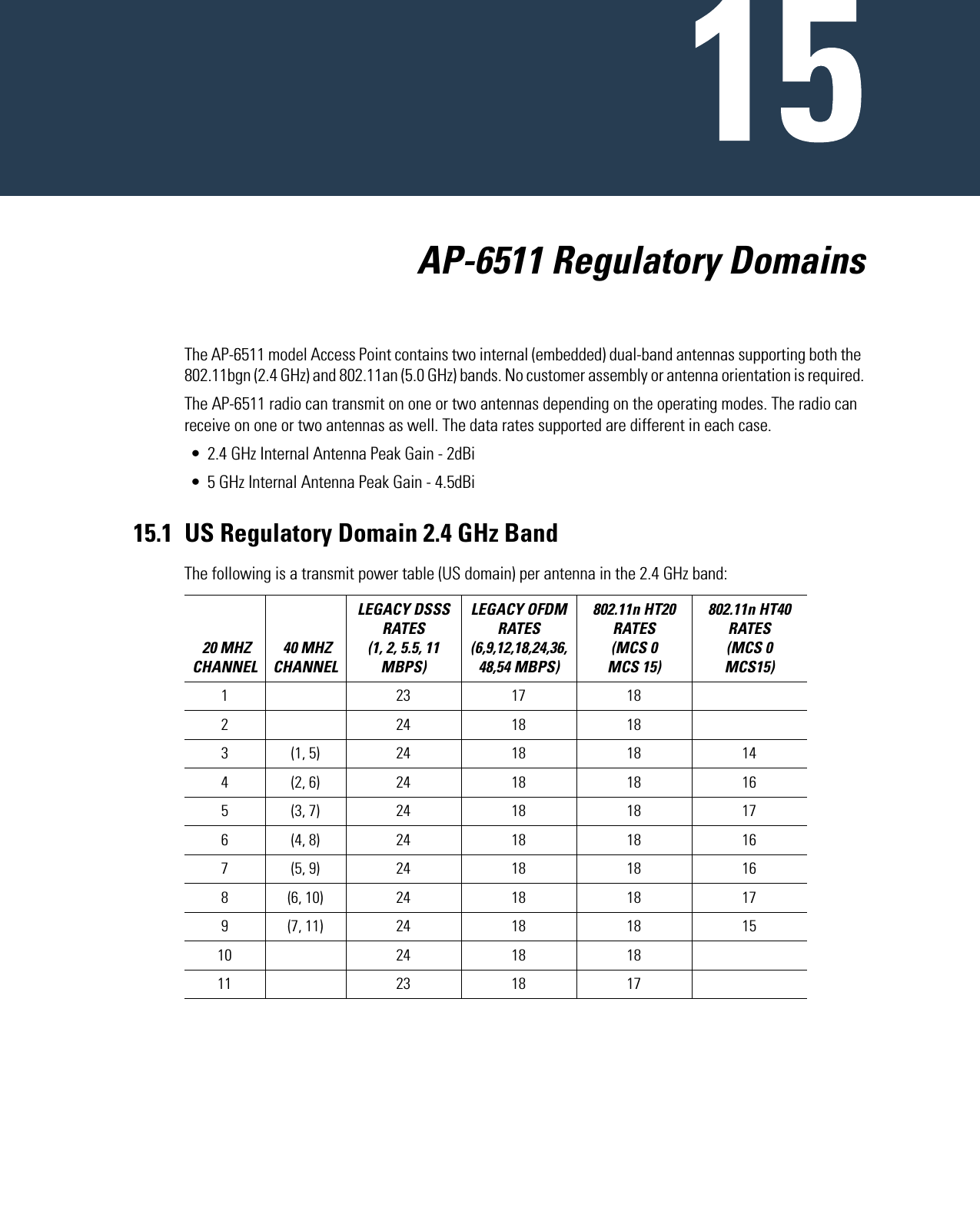
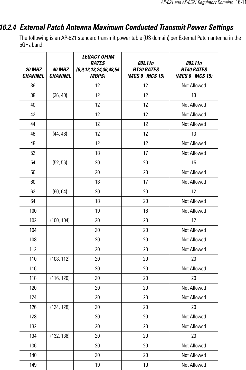
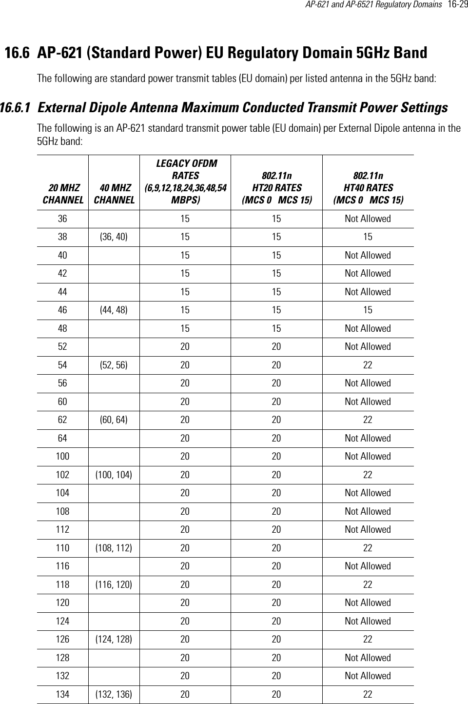
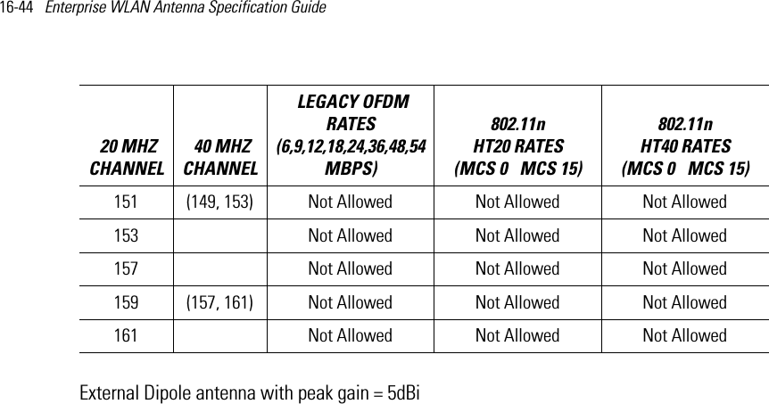
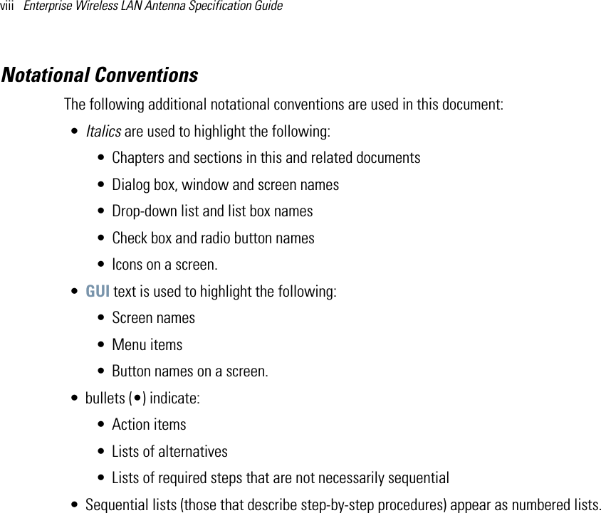
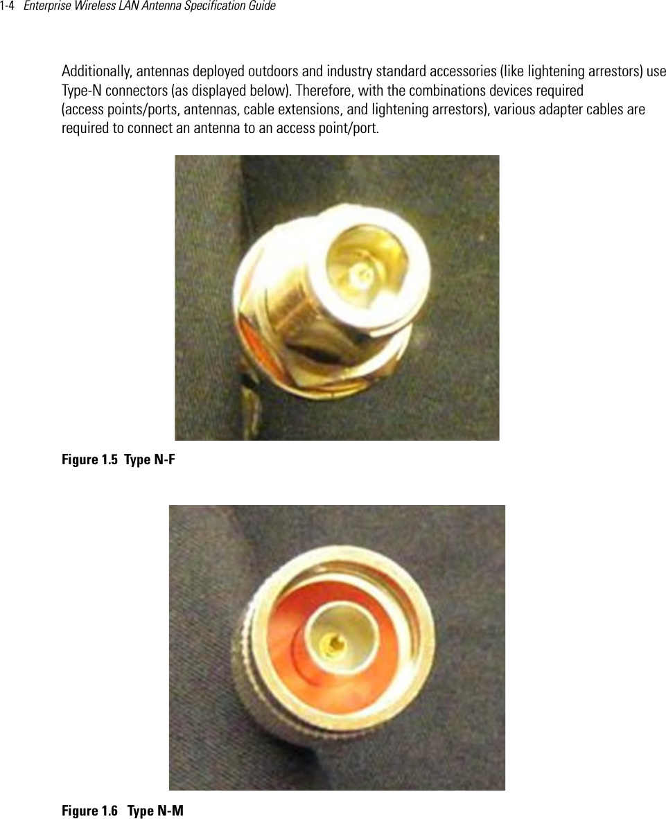
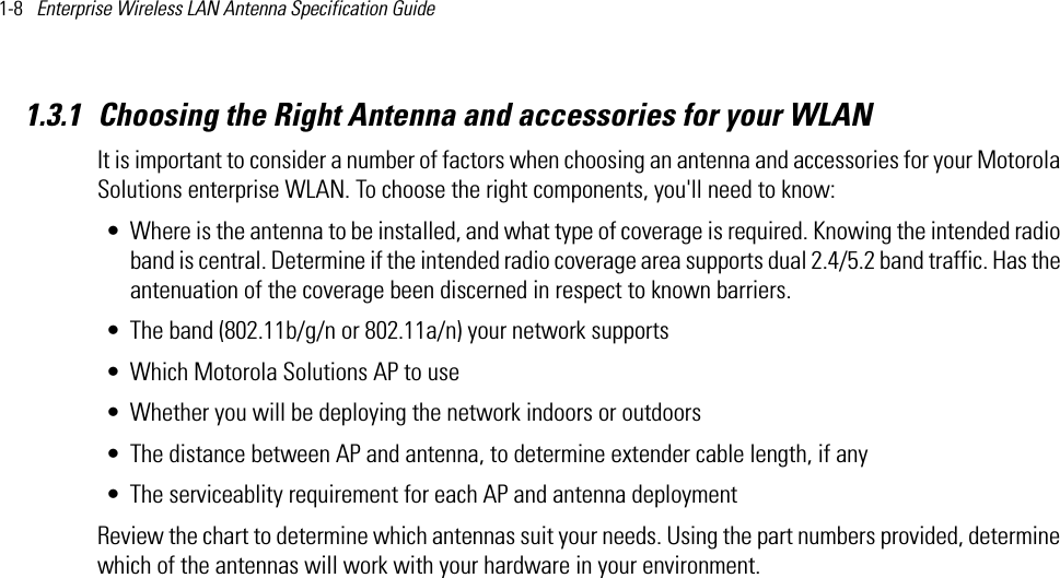
![2-6 Enterprise Wireless LAN Antenna Specification Guide 2.3 FCC USA Compaibility MatrixThe following (on the next two pages) displays Motorola Solutions FCC approved AP radio, antenna, cable and accessory combinations for use in the United States for both current and legacy access points:OK AERO. CTR TDWR #2W 097 37 43 N 35 23 34 5620 MHz 1293 97OK TULSA W 095 49 34 N 36 04 14 5605 MHz 712 113OK OKLAHOMA CITYW 097 30 36 N 35 16 34 5603 MHz 1195 64PA HANOVER W 080 29 10 N 40 30 05 5615 MHz 1266 113PR SAN JUAN W 066 10 46 N 18 28 26 5610 MHz 59 113TN NASHVILLE W 086 39 42 N 35 58 47 5605 MHz 722 97TX HOUSTON INTERCONTLW 095 34 01 N 30 03 54 5605 MHz 154 97TX PEARLAND W 095 14 30 N 29 30 59 5645 MHz 36 80TX DALLAS LOVE FIELDW 096 58 06 N 32 55 33 5608 MHz 541 80TX LEWISVILLE DFWW 096 55 05 N 33 03 53 5640 MHz 554 31UT SALT LAKE CITY W 111 55 47 N 40 58 02 5610 MHz 4219 80VA LEESBURG W 077 31 46 N 39 05 02 5605 MHz 361 113WI MILWAUKEE W 088 02 47 N 42 49 10 5603 MHz 820 113STATE CITY LONGITUDE LATITUDE FREQUENCY TERRAIN ELEVATION (MSL) [ft]ANTENNA HEIGHT ABOVE TERRAIN [ft]](https://usermanual.wiki/Zebra-Technologies/AP6.Antenna-Installation-Guide-050412/User-Guide-1702053-Page-20.png)