Zebra Technologies AP6 Access Point Radio Module 6 User Manual 6521 IG
Zebra Technologies Corporation Access Point Radio Module 6 6521 IG
Contents
- 1. Manual
- 2. Antenna Installation Guide 050412
- 3. AP 6511 Install Guide Rev B 050412
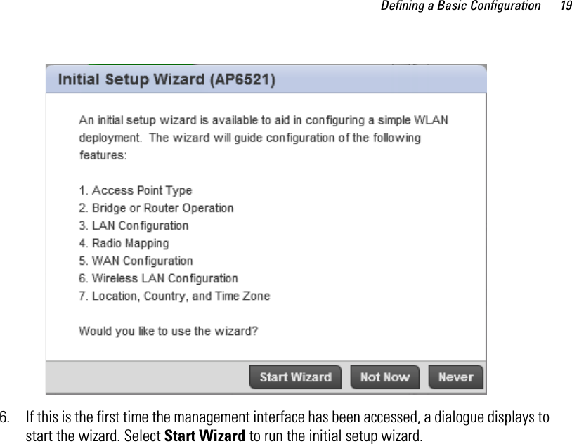
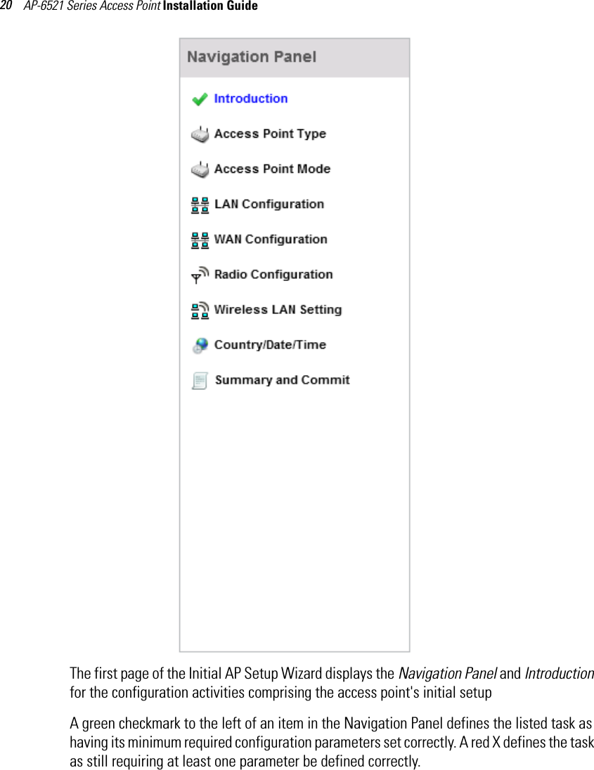
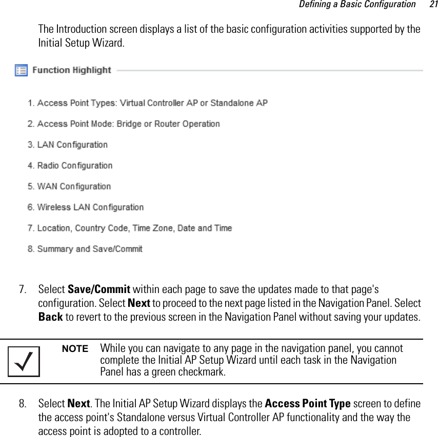
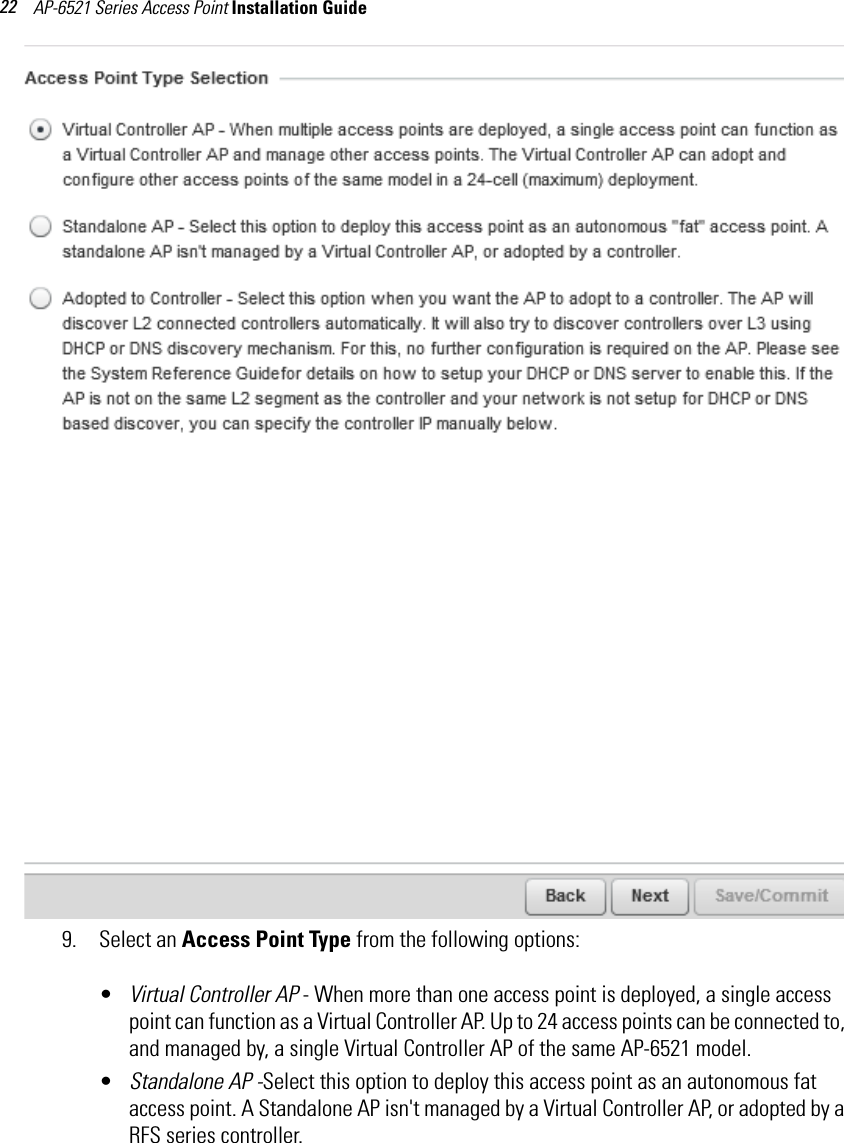
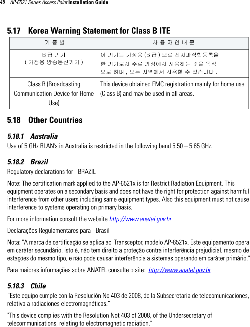
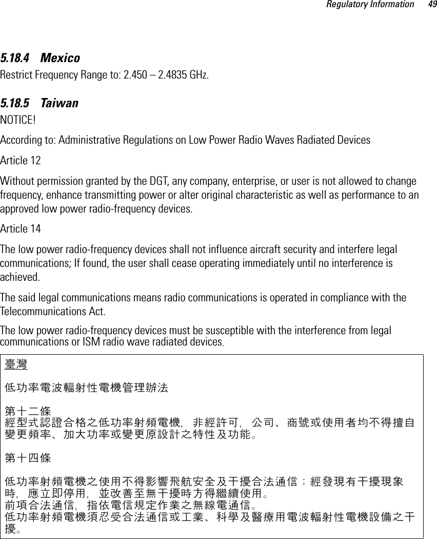
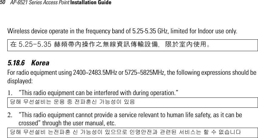
- 4. AP 6521 Install Guide Rev B 050412
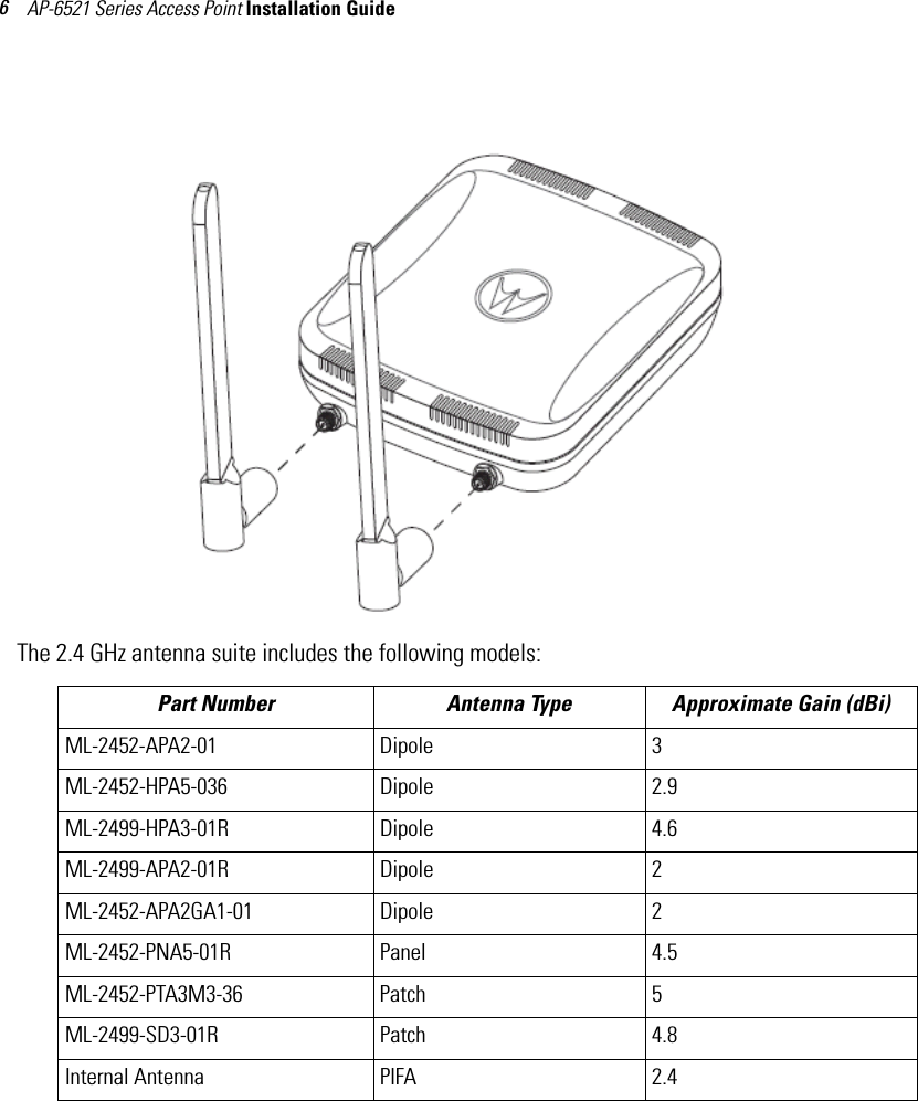
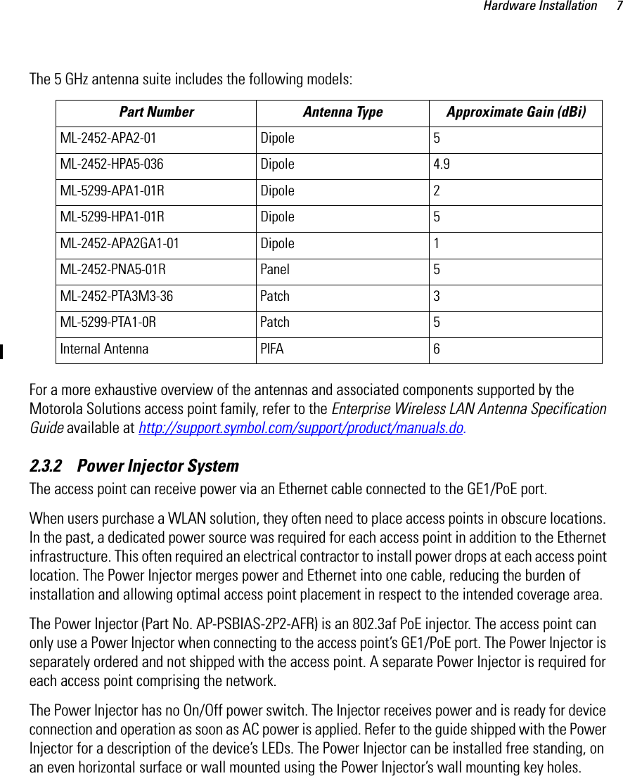
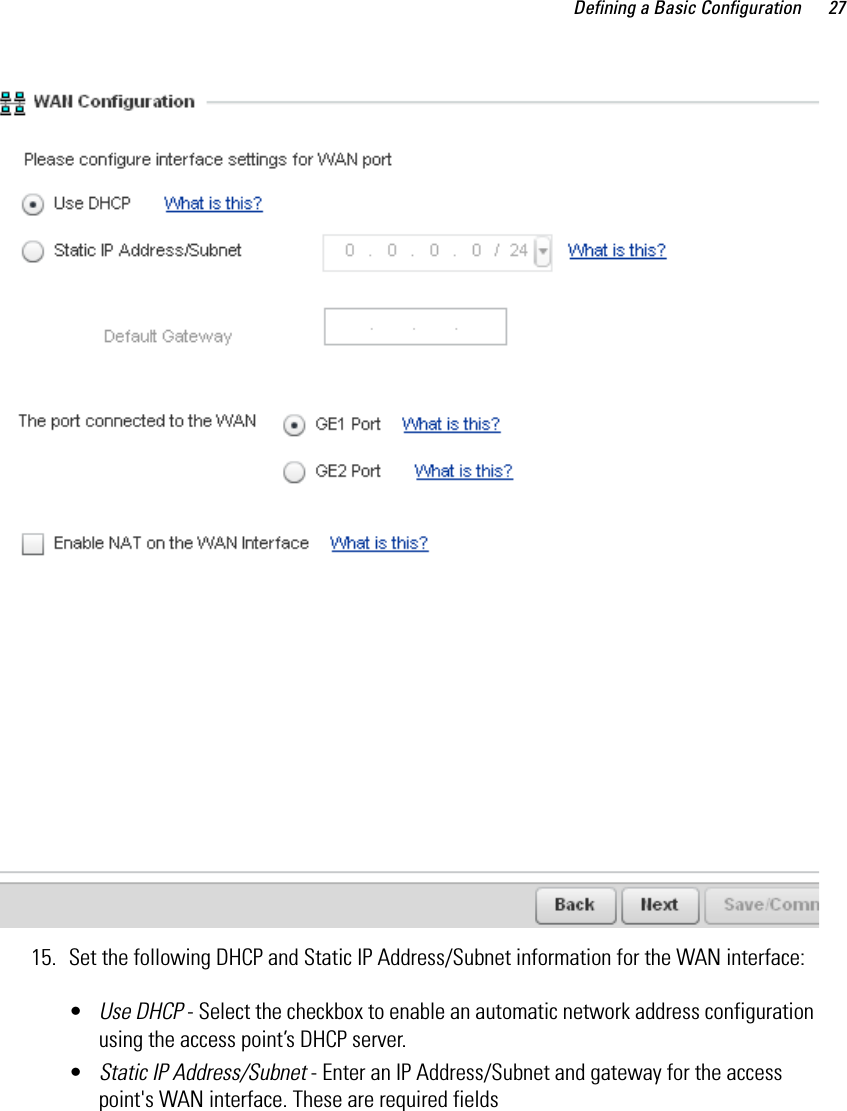
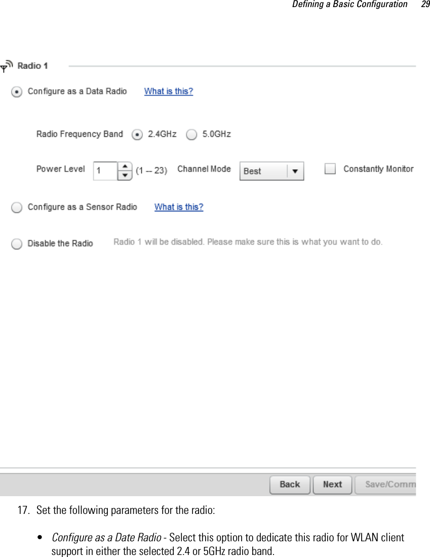
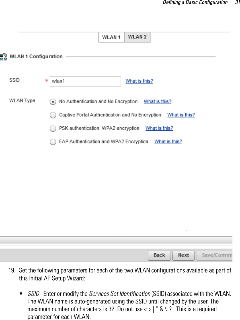
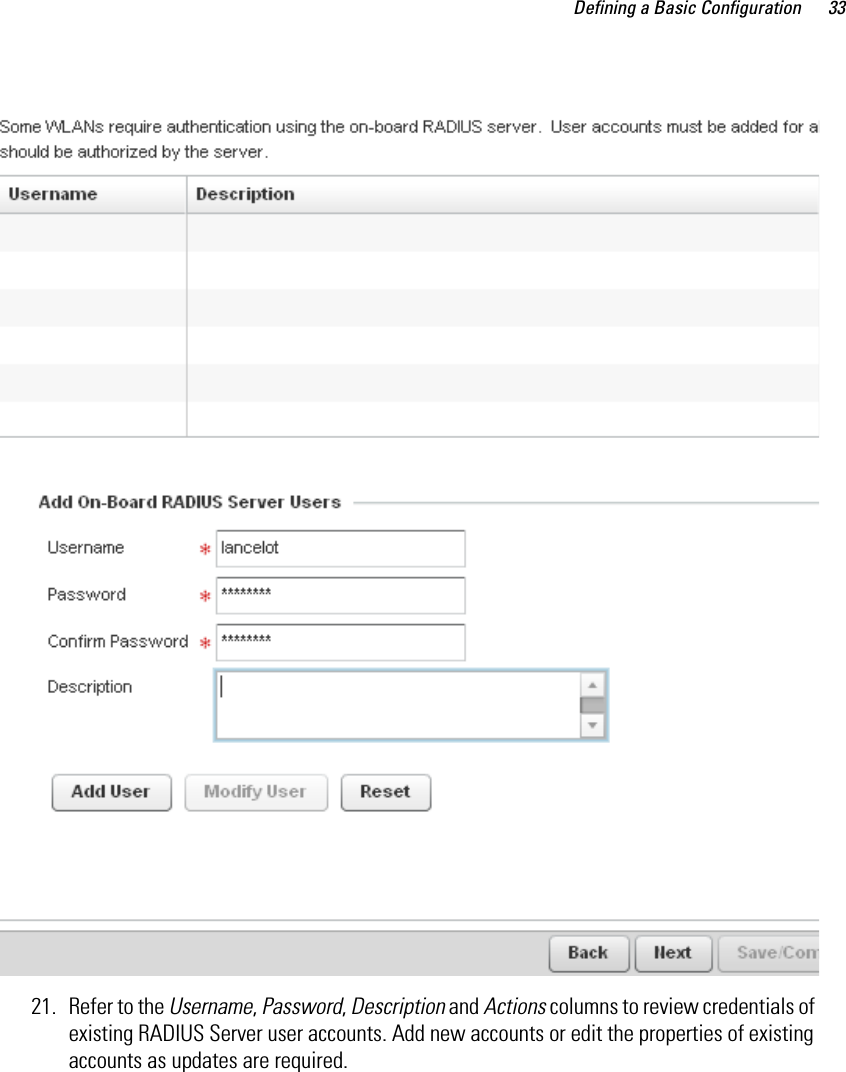
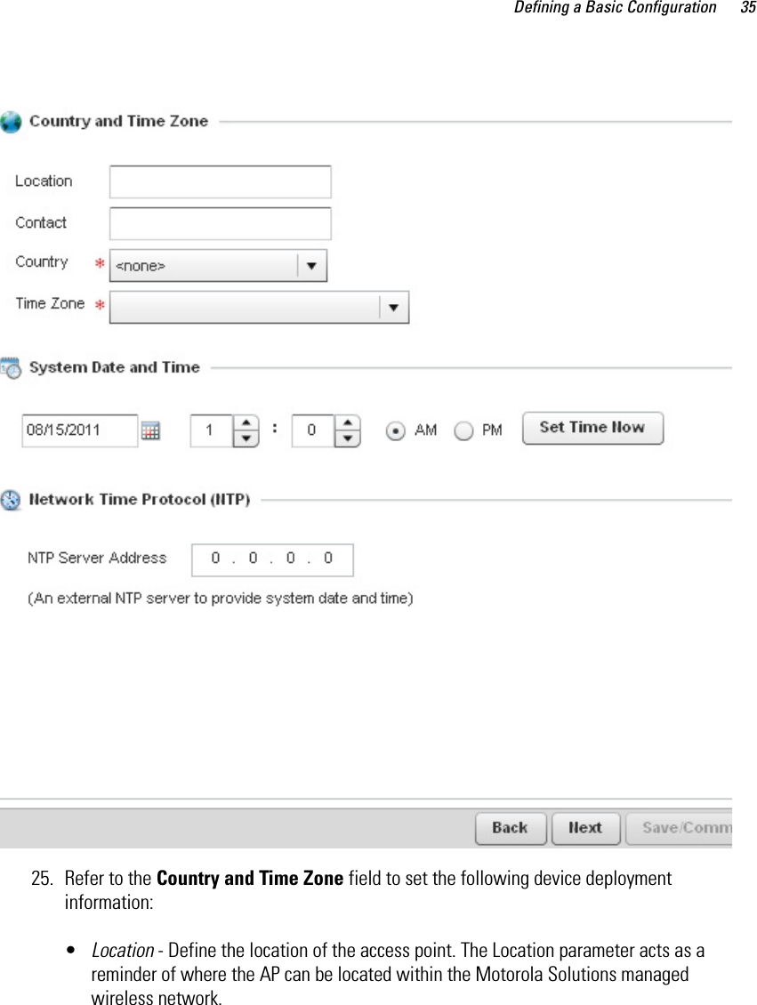
AP 6521 Install Guide Rev B 050412