Zebra Technologies DS6878 Barcode scanner with integrated Bluetooth User Manual Symbol DS6878 Product Reference Guide
Zebra Technologies Corporation Barcode scanner with integrated Bluetooth Symbol DS6878 Product Reference Guide
Contents
- 1. User Manual II
- 2. User Manual III
- 3. User Manual I
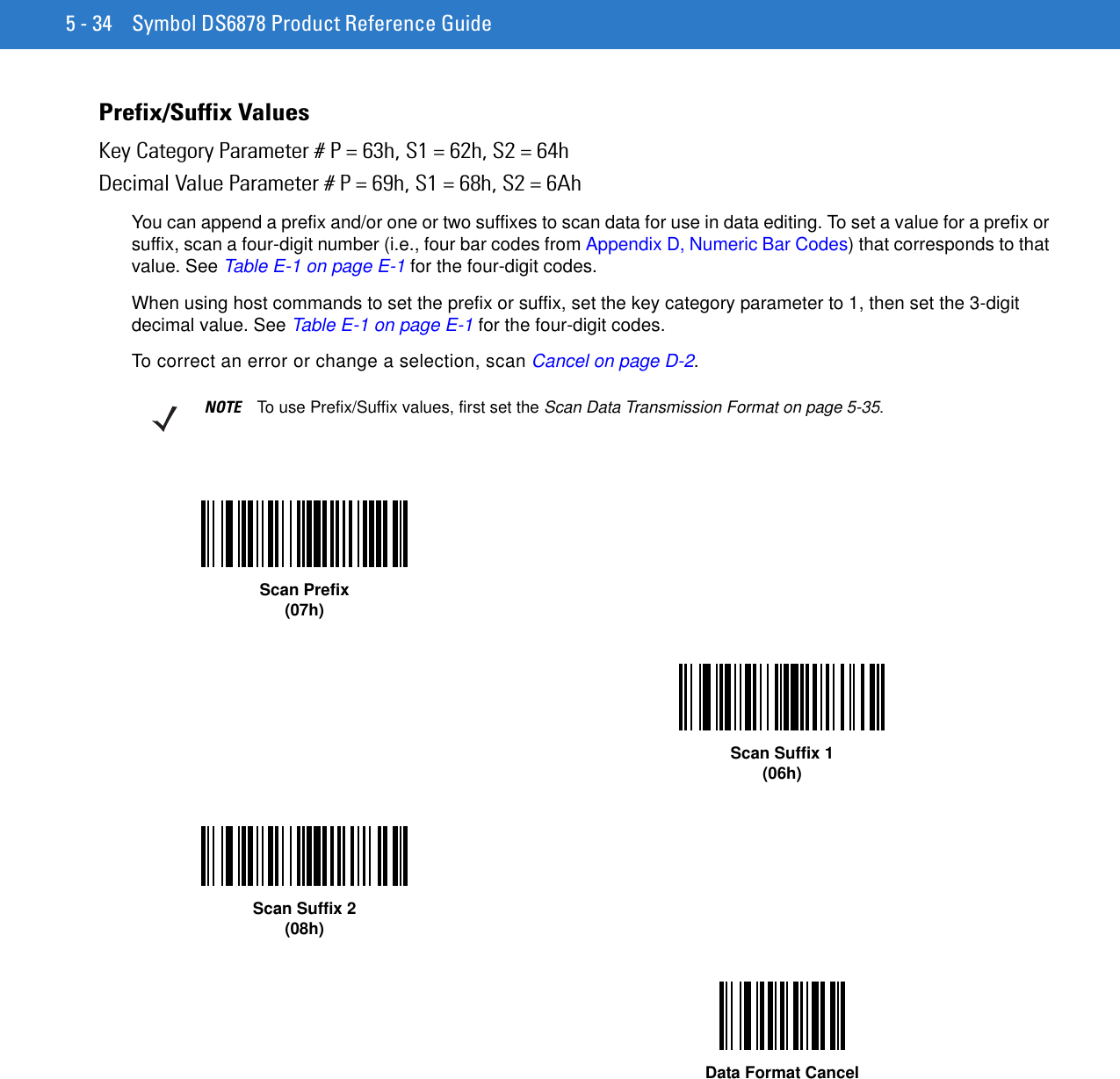
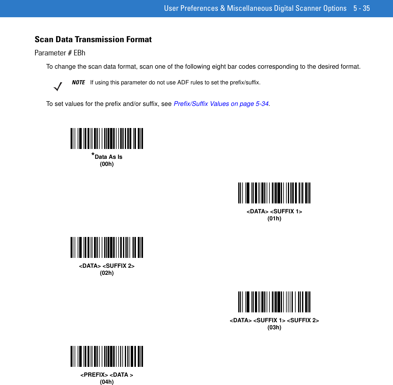
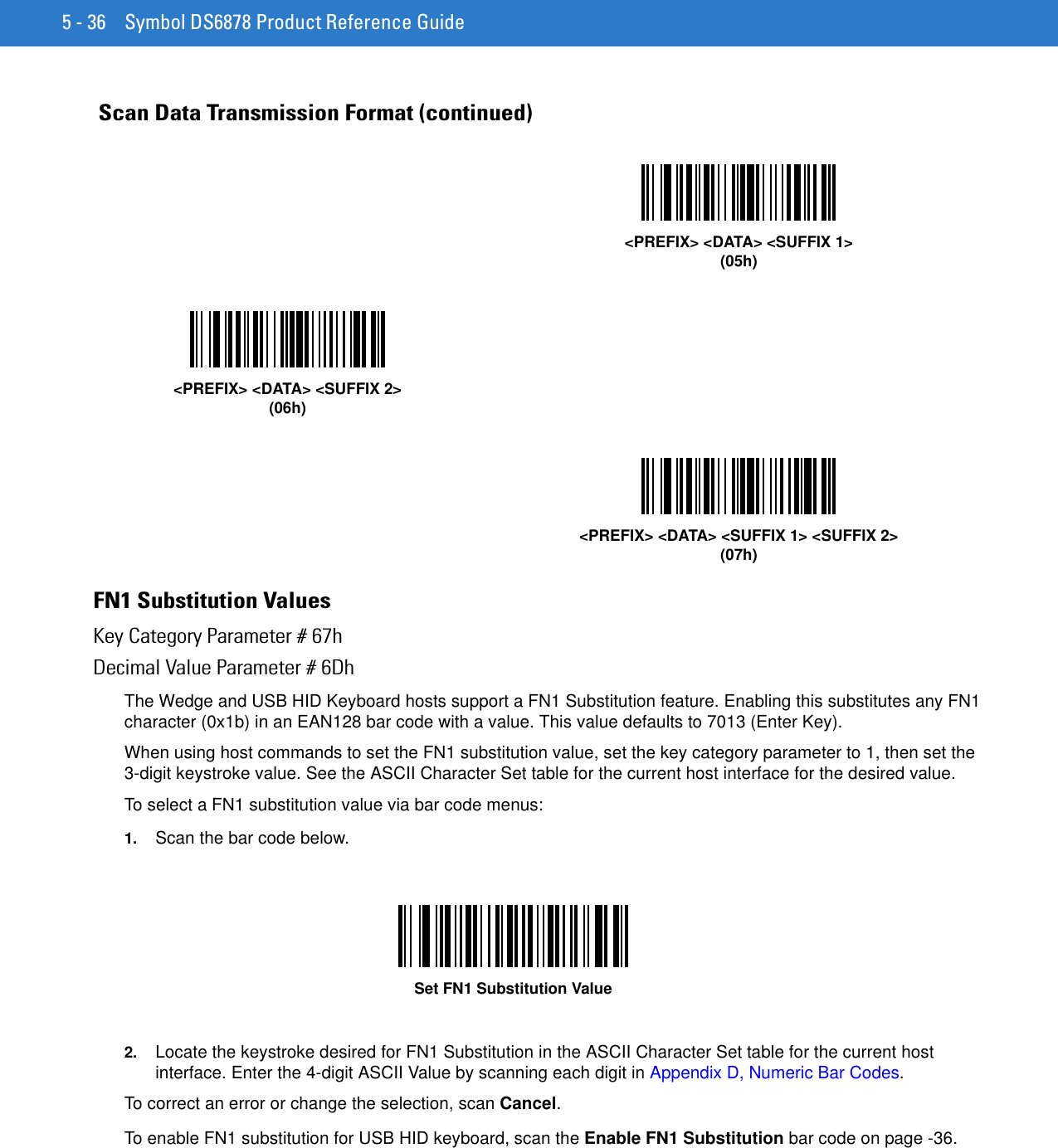
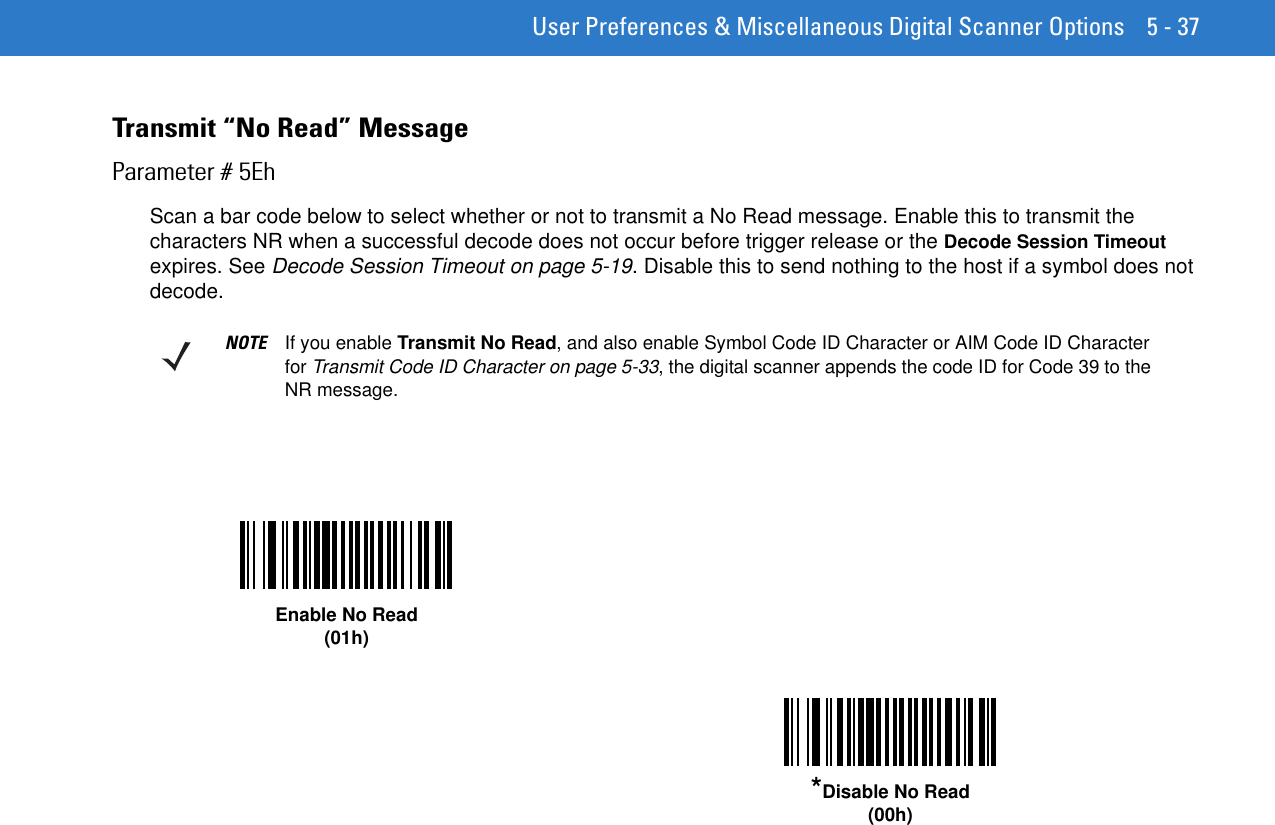
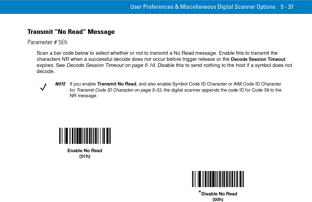
User Manual I
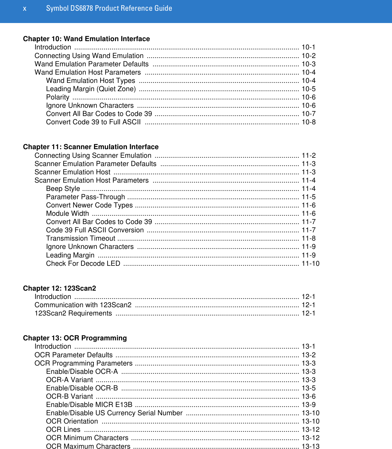
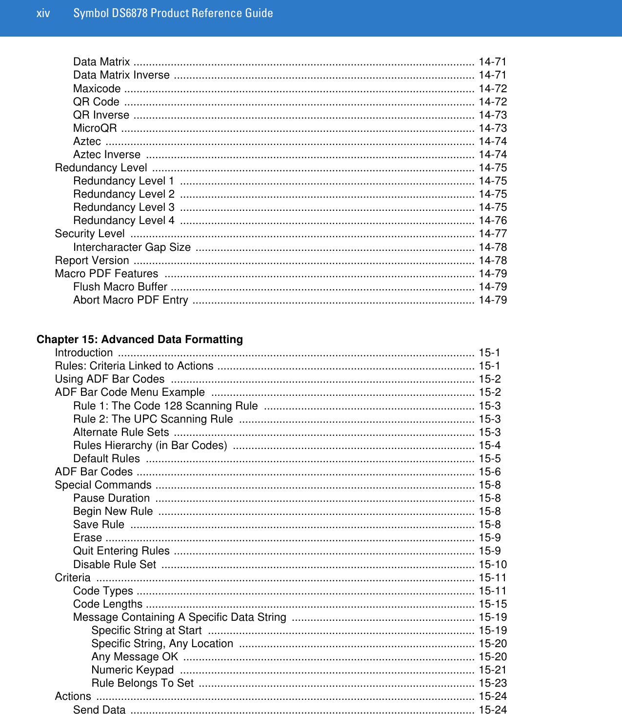

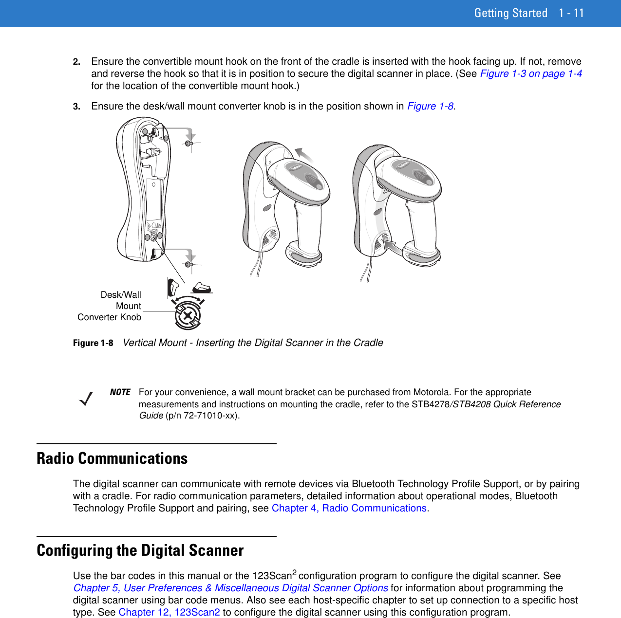

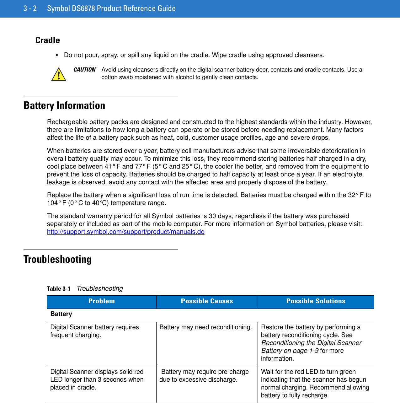
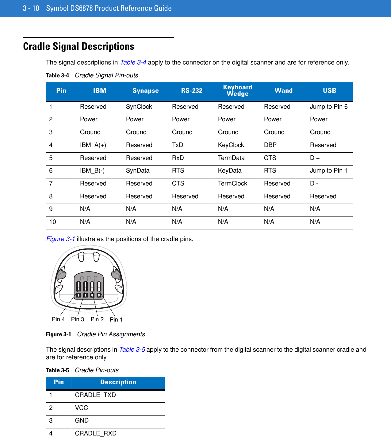
![5 - 24 Symbol DS6878 Product Reference GuideMulticode ExpressionParameter # F1h, 95hUse this feature to program a multicode expression for Multicode Mode (grid method). The default is 1, which indicates any bar code.To set the multicode expression: 1. Scan the bar code below.2. Scan bar codes from the alphanumeric keyboard in the Advanced Data Formatting Programmer Guide to define the expression. 3. Scan the End of Message bar code from the Advanced Data Formatting Programmer Guide.Multicode Expression Syntax[n] [Element 1]; [Element 2 ]; ... [Element n];Where:•n is the number of elements in the overall expression. The multicode expression describes the bar code(s) that the digital scanner can expect to find in an image. Each element represents one bar code in the digital scanner's field of view. The order of elements in the expression is the order in which bar code data from each element transmits to the host. Elements are defined using one or more of the following methods:•By Region. This type of element limits decoding to a specific area within the digital scanner's field of view. Region coordinates are defined as the top left and bottom right corners of the region, expressed in percentages of the field of view. These can range from 0% to 100%, or 0x00 to 0x64 in hex, for both horizontal and vertical axes. A region element is constructed as:[R] [4] [Top, Left] [Bottom, Right]Where:•[R] is the character R•[4] is 0x04, indicating there are four bytes thereafter to describe the region•[Top, Left] are two values representing the top left corner of the region•[Bottom, Right] are two values representing the bottom right corner of the region•By Code Type. An element can specify a specific bar code symbology to find and decode somewhere in the field of view. A code type element is constructed as:[C] [2] [Code Type]Multicode Expression](https://usermanual.wiki/Zebra-Technologies/DS6878.User-Manual-I/User-Guide-1246132-Page-106.png)
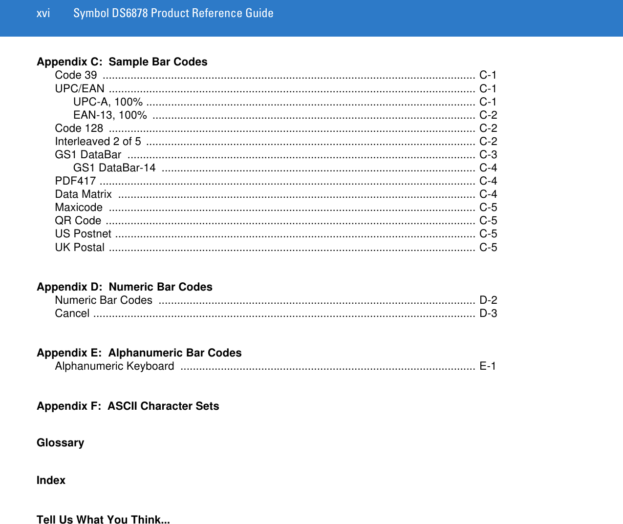
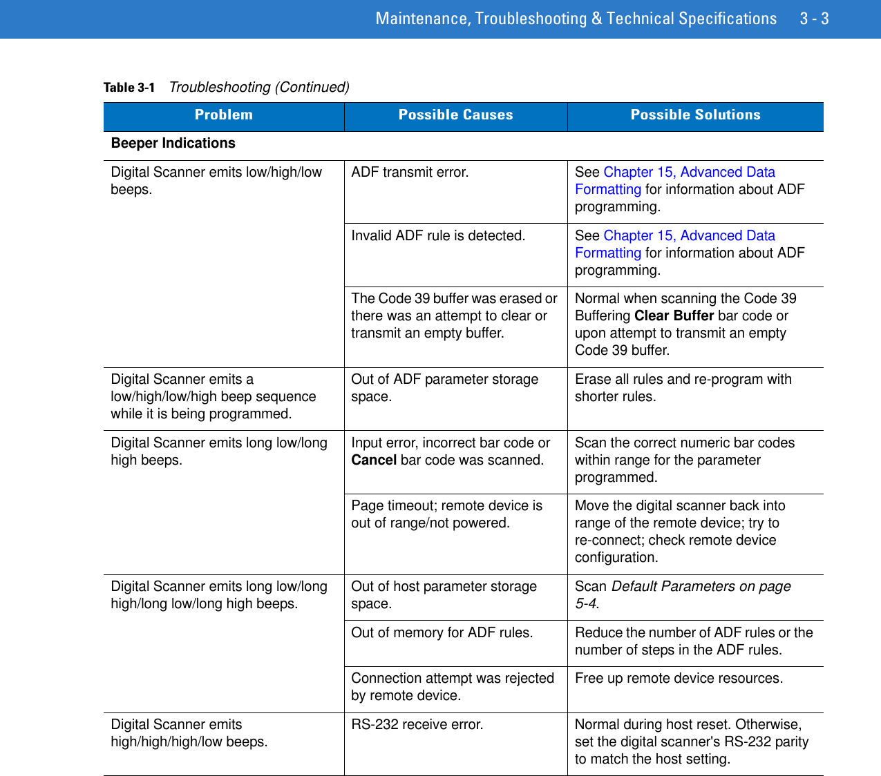
![User Preferences & Miscellaneous Digital Scanner Options 5 - 25Where: •[C] is the character C•[2] is 0x02, indicating there are two bytes thereafter to describe the code type•[Code Type] is the desired symbology's parameter number (see Chapter 14, Symbologies). For single-byte parameter numbers, extend the value to two bytes by adding 00 before the parameter number. Defining Multicode Expression NotesWhen defining multicode expressions consider the following:•Use the Code Type specifier if there are bar codes of more than one code type in view.•Always use the Region specifier when there are multiple bar codes of the same code type.•When transmission order is important (the first element in the expression transmits first), use either type to define the order.•When there are unwanted bar codes in view, filter them out in one of two ways:•Use Code Type to specify only the target bar codes.•Use Region to identify only the target bar codes.•If the expression does not contain a Region specifier, scanning angle and distance do not matter. If you specify a region you must scan in a fixed orientation and at a fixed distance. Because of this, it is preferable to use the Code Type specifier rather than the Region specifier.•When defining regions:•Defining a region much larger than the bar code improves tolerance to scan distance and angle, but can cause a decode of a nearby bar code instead of the target bar code. Therefore, for best performance define larger regions when only a few bar codes are in view and those in view are widely separated.•Defining a region close to (or smaller than) the target bar code improves the probability of decoding this bar code rather than one nearby, but scan distance and angle must be more accurate. Therefore, for best performance define small regions when many bar codes are in view or those in view are close together.•Use Region elements to improve decode speeds by reducing the image area to search for the target bar code.•Specifying Code Type may also improve decode speeds for some code types.•Although you can scan parameter bar codes when multicode mode is enabled, be aware of the following: If the multicode expression defined a region(s), to scan a parameter bar code you must position the bar code within the first region defined in the expression. In some cases, this first region is not the center of the image and aiming at the parameter bar code does not result in a successful decode.The following examples show the multicode expressions in both hex and decimal formats, however in the sample figures the values are decimal. Be sure to use the correct base numbering system when creating an expression. A region specified as 0x00 0x00 0x64 0x32 represents a region with coordinates of Top-Left (0,0) and Bottom Right (100,50).](https://usermanual.wiki/Zebra-Technologies/DS6878.User-Manual-I/User-Guide-1246132-Page-107.png)
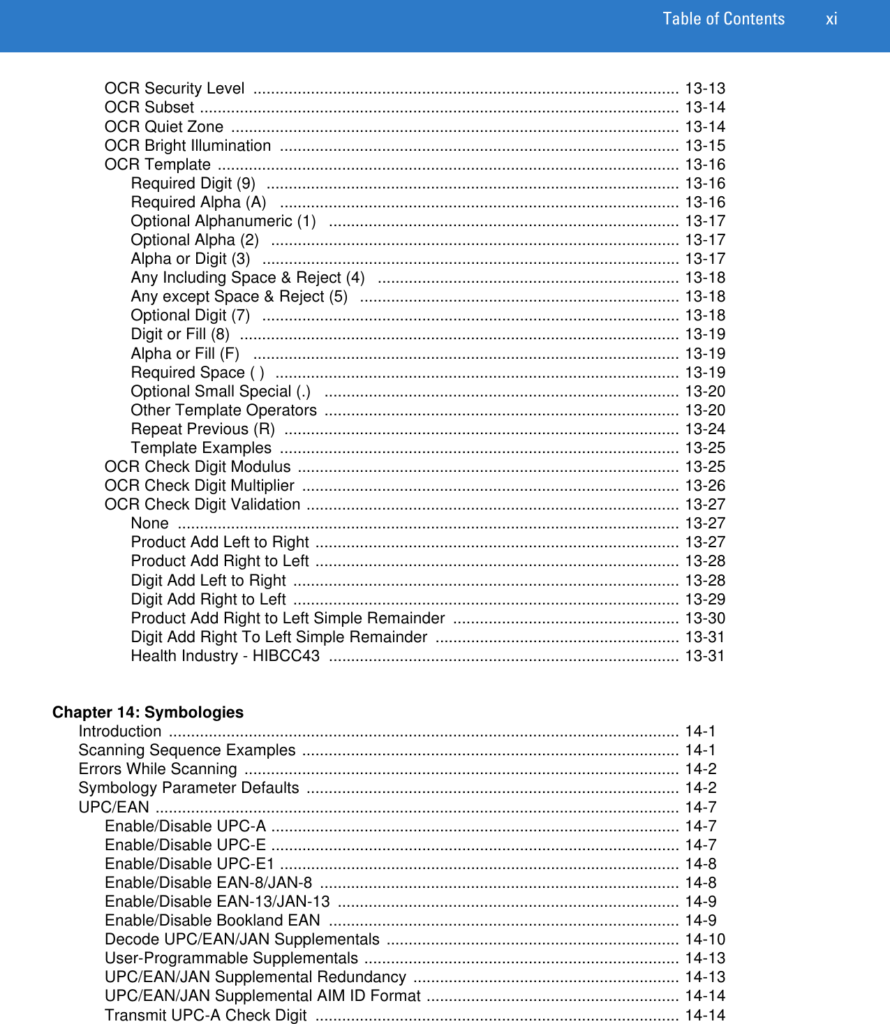
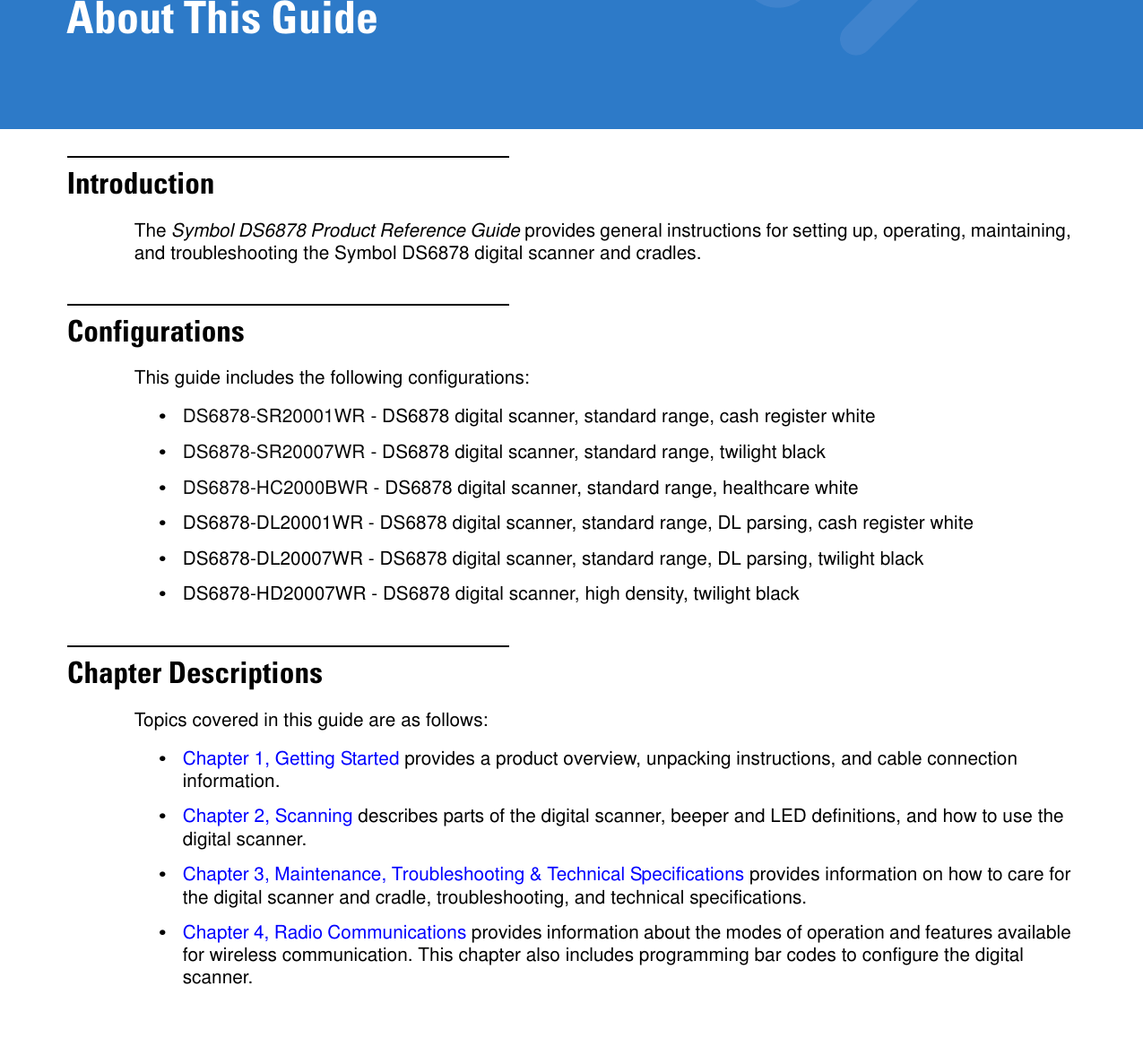
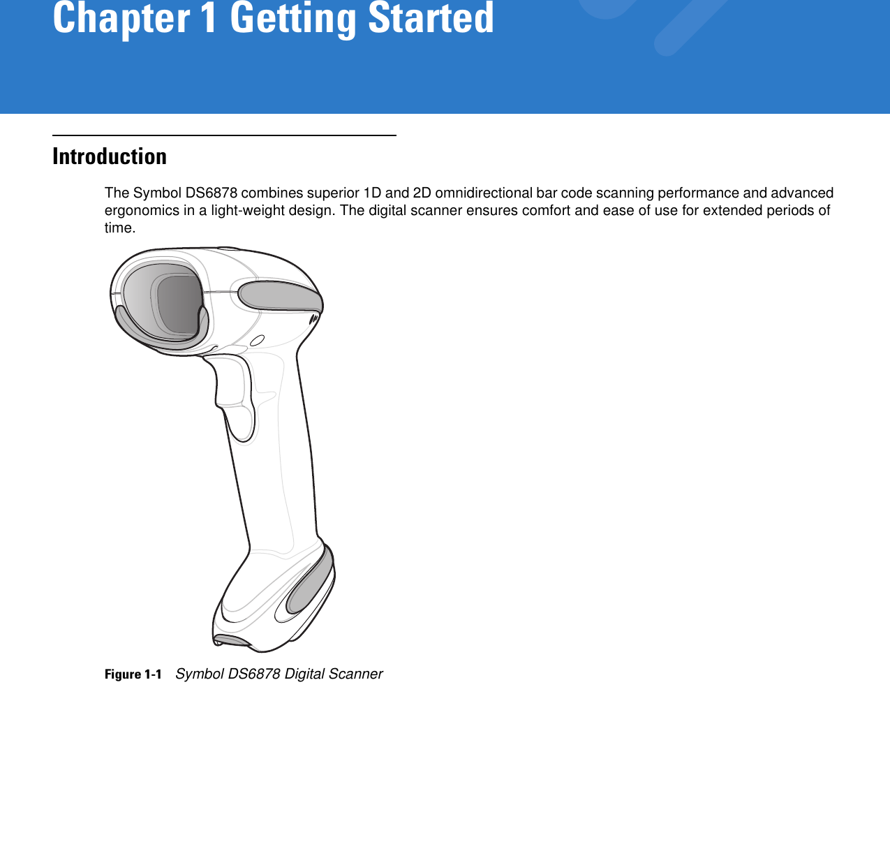
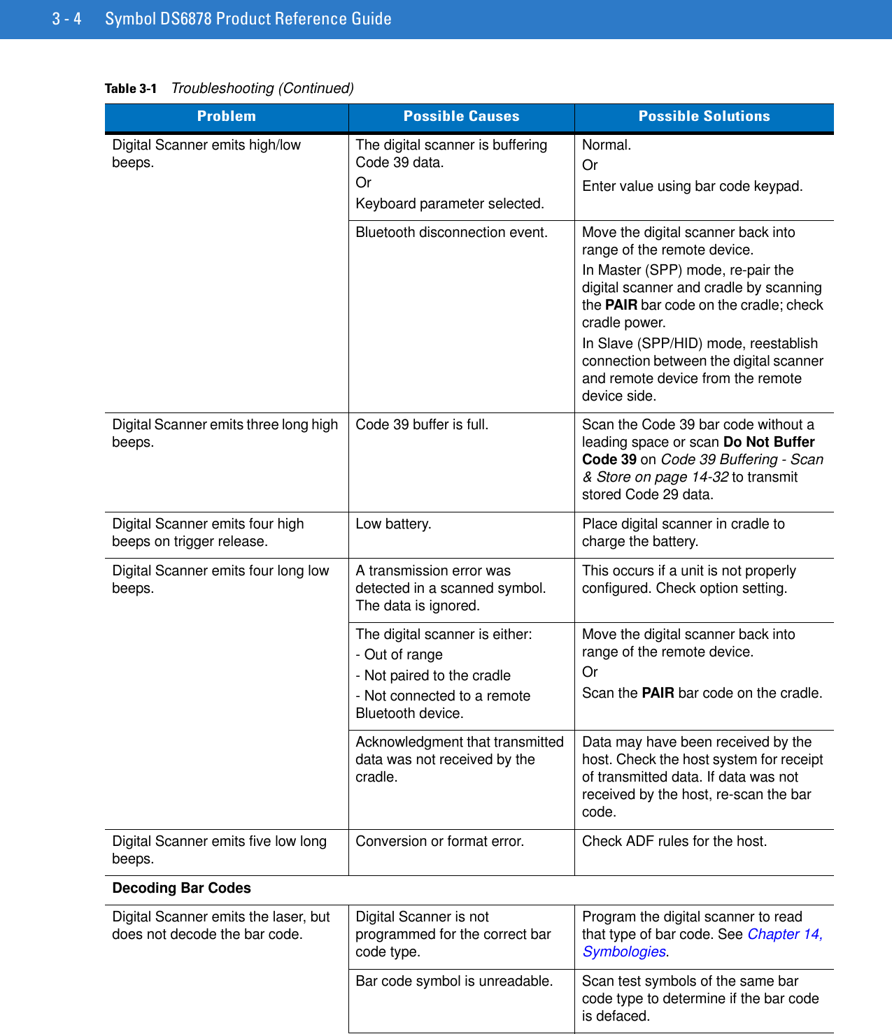
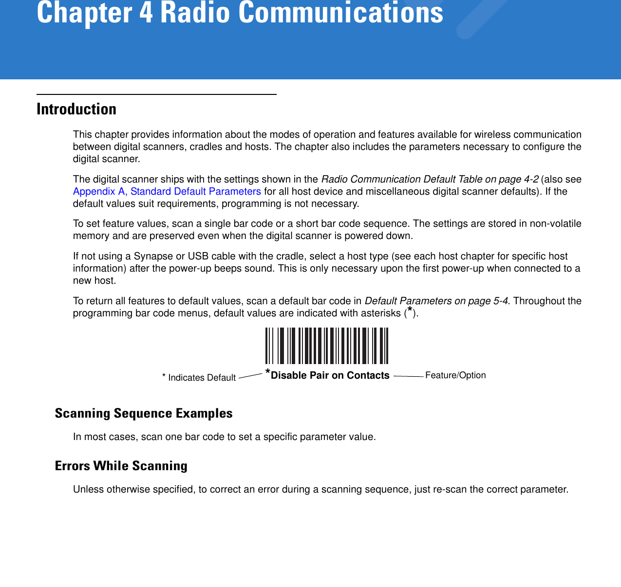
![5 - 26 Symbol DS6878 Product Reference GuideExample 1To decode one Code 128 bar code anywhere in the image (even when bar codes of other types are in view), as in Figure 5-1, program the expression as follows:The expression in decimal is (formatted for readability): 1 C 2 0 8 ;To program the expression via scanning parameters the sequence is (spaces are for readability): [MultiCode-Expression] 01 C 02 00 08 ; [End Of Message]To program the expression via host command (SSI/SNAPI) the sequence is: 0x01 0x43 0x02 0x00 0x08 0x3b Figure 5-1 Multicode Expression Example 101234567890550%0%100%0% 50% 100%PDF417 CodeCode 128 CodeUPC-A Code](https://usermanual.wiki/Zebra-Technologies/DS6878.User-Manual-I/User-Guide-1246132-Page-108.png)
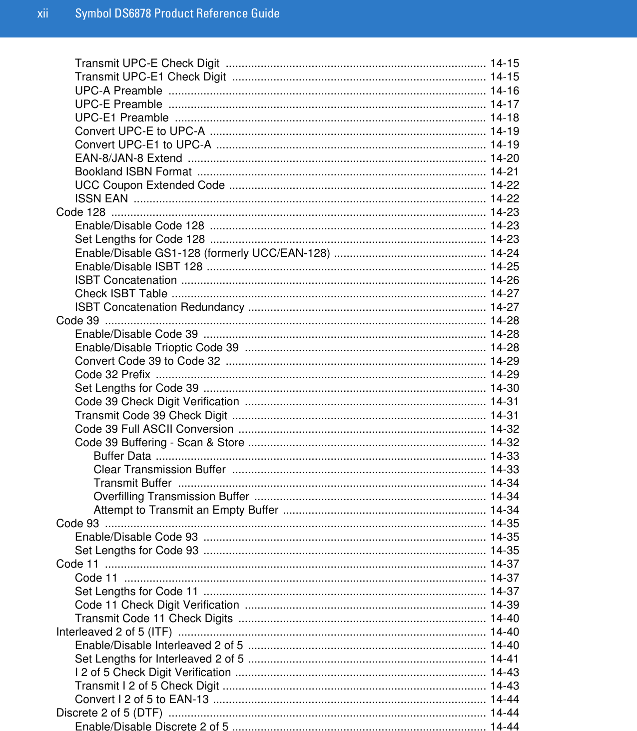
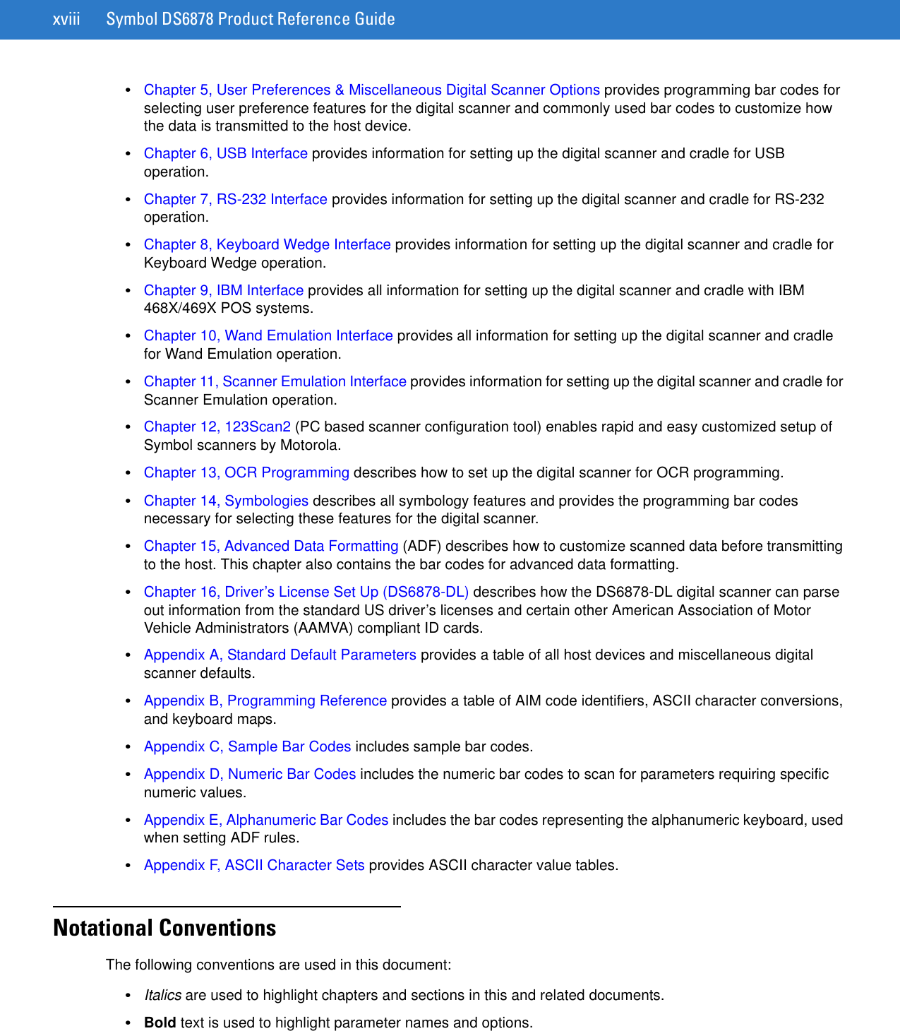
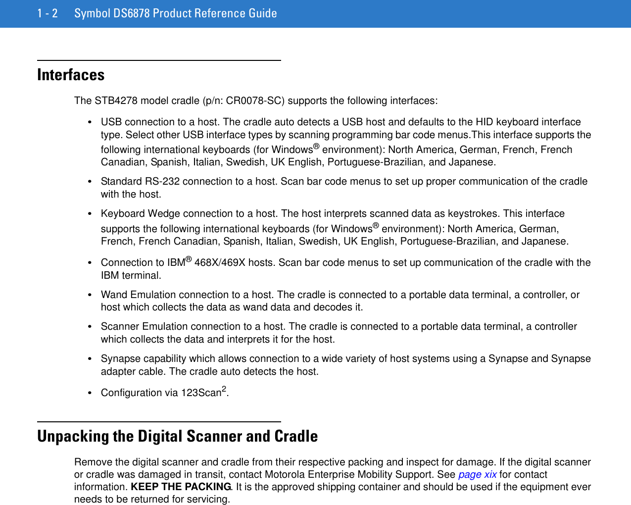
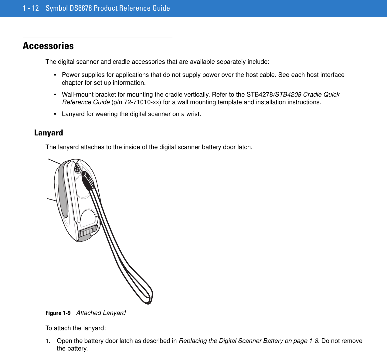
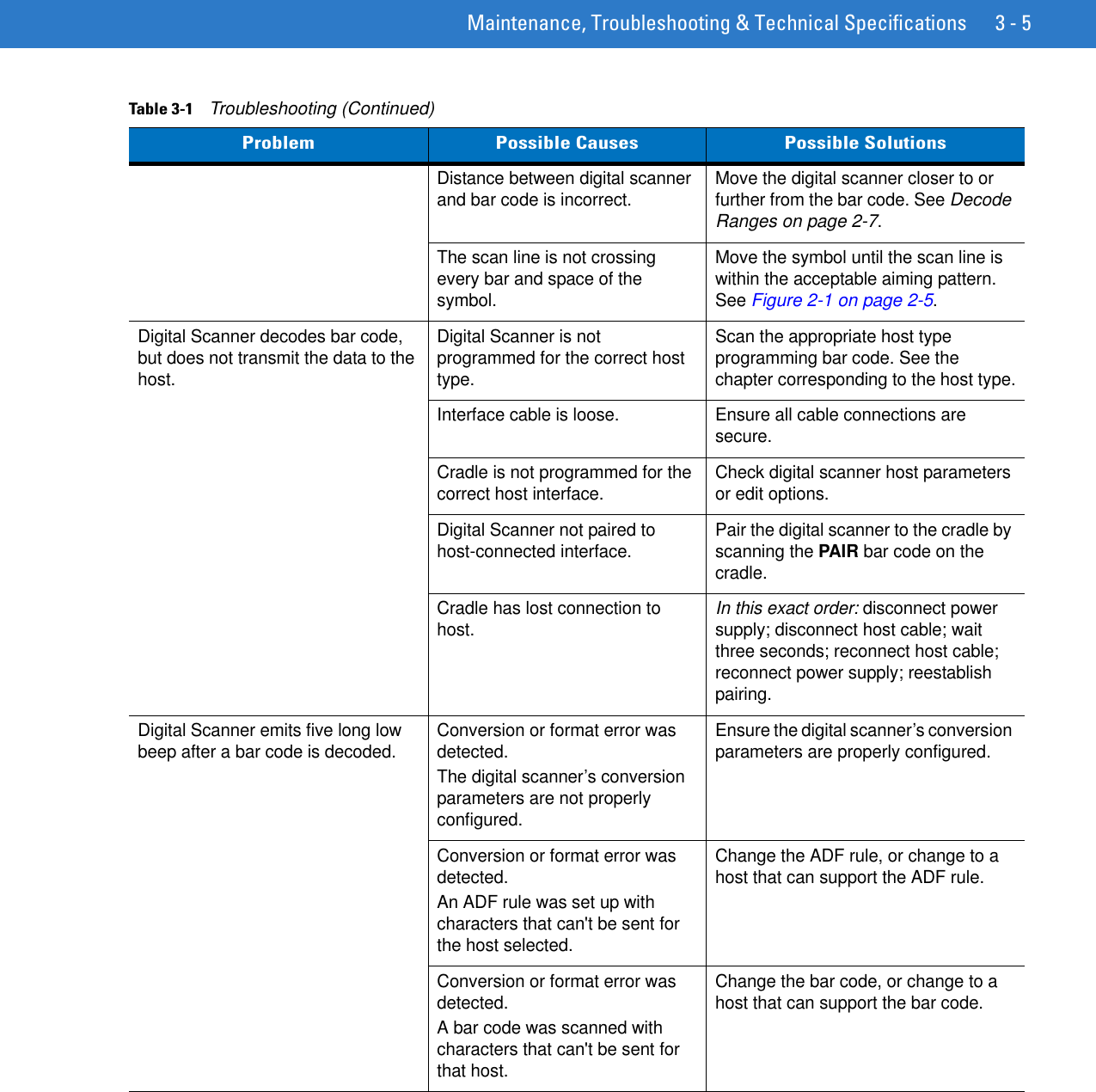
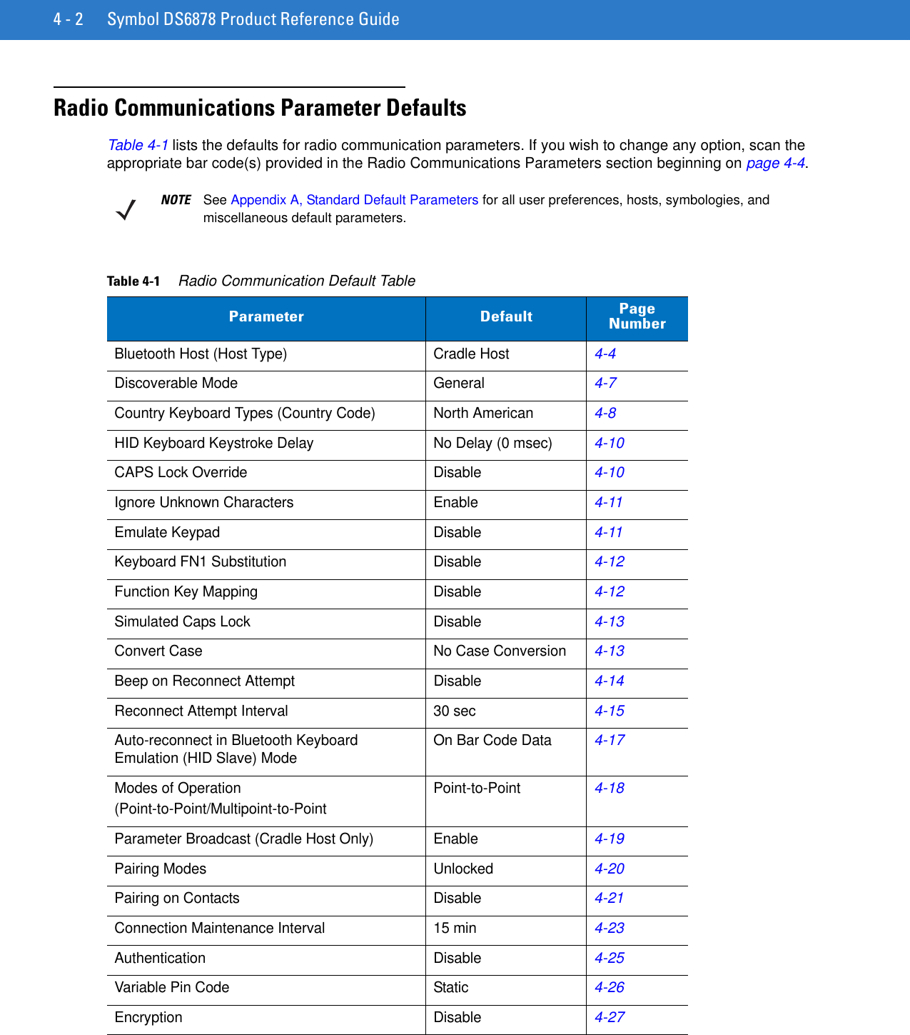
![User Preferences & Miscellaneous Digital Scanner Options 5 - 27Example 2aTo decode a Code128 (Code Type=8) on the top half of the image and a PDF417 (Code Type=15) on the bottom half of the image, as in Figure 5-2, program the expression as follows:The expression in decimal is (formatted for readability):2 C 2 0 8 R 4 0 0 100 50 ; C 2 0 15 R 4 0 50 100 100 ;To program the expression via scanning parameters the sequence is:[MultiCode-Expression] 02 C 02 00 08 R 04 00 00 64 32 ; C 02 00 0F R 04 00 32 64 64 ; [End Of Message]To program the expression via host command (SSI/SNAPI) the sequence is:0x02 0x43 0x02 0x00 0x08 0x52 0x04 0x00 0x00 0x64 0x32 0x3B 0x43 0x02 0x00 0x0F 0x52 0x04 0x00 0x32 0x64 0x64 0x3BExample 2bIn Figure 5-2, if the bottom PDF417 bar code must transmit first, reverse the sequence of the two bar codes:The expression in decimal is (formatted for readability):2 C 2 0 15 R 4 0 50 100 100 ; C 2 0 8 R 4 0 0 100 50 ;To program the expression via scanning parameters the sequence is:[MultiCode-Expression] 02 C 02 00 0F R 04 00 32 64 64 ; C 02 00 08 R 04 00 00 64 32 ; [End Of Message]To program the expression via host command (SSI/SNAPI) the sequence is:0x02 0x43 0x02 0x00 0x0F 0x52 0x04 0x00 0x32 0x64 0x64 0x3B 0x43 0x02 0x00 0x08 0x52 0x04 0x00 0x00 0x64 0x32 0x3BFigure 5-2 Multicode Expression Example 2PDF417 Code(0,0)Code 128 Code(0,50)(160,100)(100,50)50%0%100%0% 50% 100%](https://usermanual.wiki/Zebra-Technologies/DS6878.User-Manual-I/User-Guide-1246132-Page-109.png)
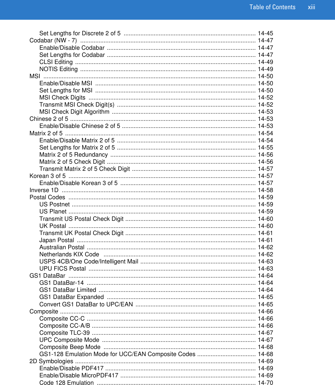
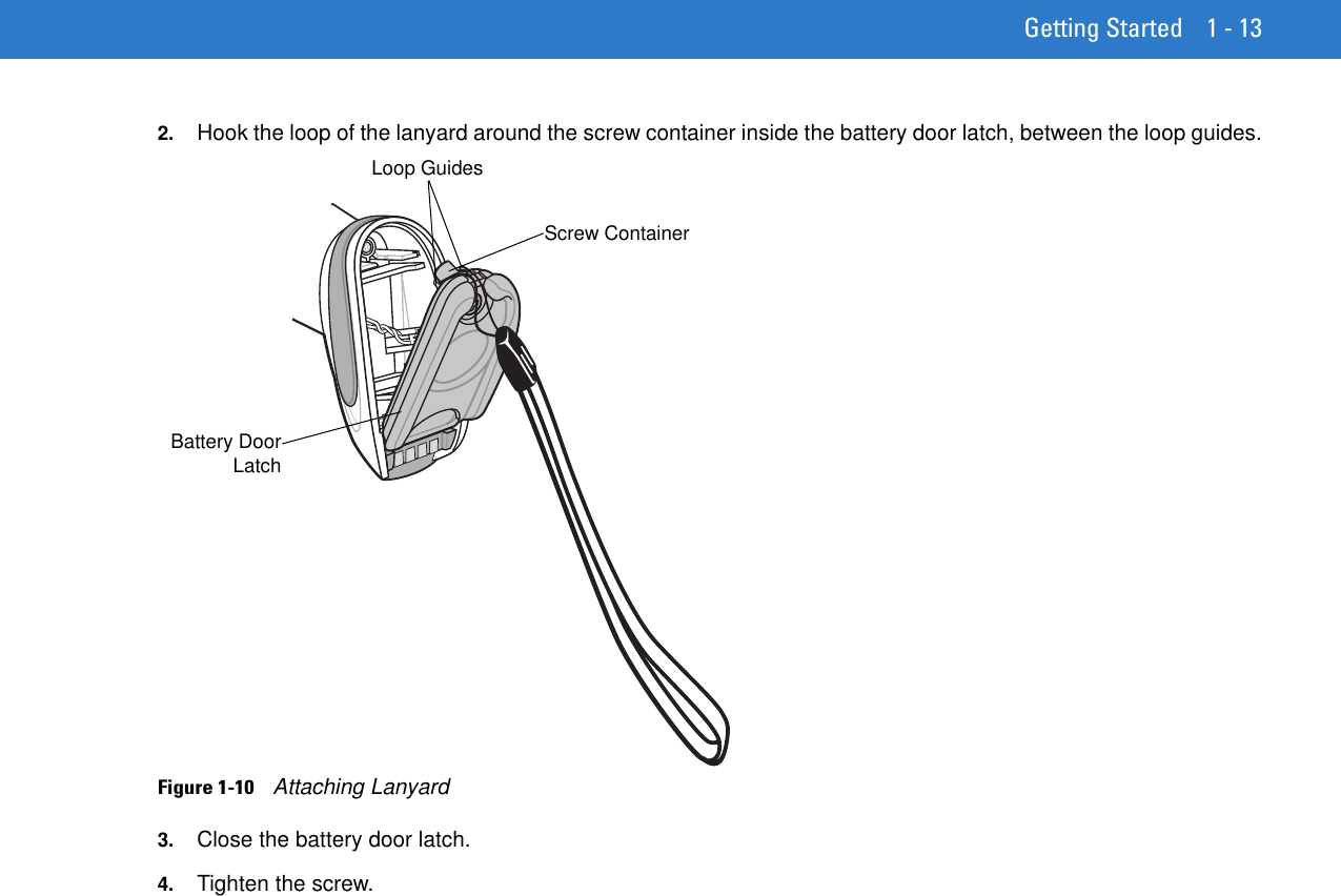
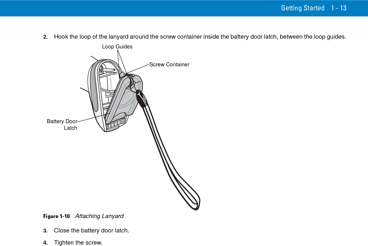
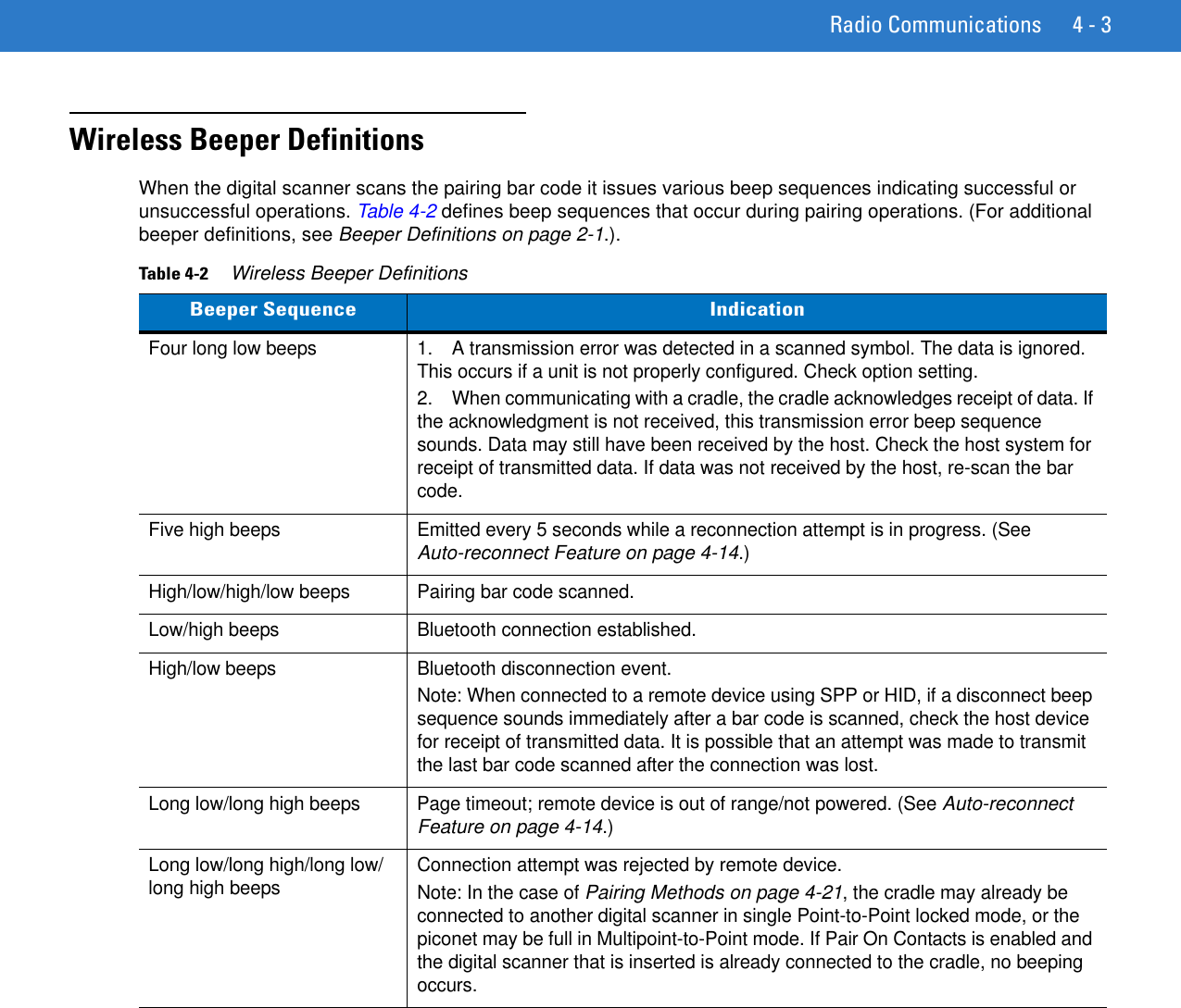
![5 - 28 Symbol DS6878 Product Reference GuideExample 3To decode the set of three bar codes while excluding the center Code 128 bar code, as in Figure 5-3, the expression is:The expression in decimal is (formatted for readability):3 C 2 0 15 R 4 0 0 50 50 ; C 2 [F0 24] R 4 70 0 100 40 ; C 2 0 8 R 4 65 60 100 100 ;To program the expression via scanning parameters the sequence is:[MultiCode-Expression] 03 C 02 00 0F R 04 00 00 32 32 ; C 02 F0 24 R 04 46 00 64 28 ; C 02 00 08 R 04 41 3C 64 64 ; [End Of Message]To program the expression via host command (SSI/SNAPI) the sequence is:0x03 0x43 0x02 0x00 0x0F 0x52 0x04 0x00 0x00 0x32 0x32 0x3B 0x43 0x02 0xF0 0x24 0x52 0x04 0x46 0x00 0x64 0x28 0x3B 0x43 0x02 0x00 0x08 0x52 0x04 0x41 0x3C 0x64 0x64 0x3BFigure 5-3 Multicode Expression Example 3 40%65%40%40%PDF417 CodeCode 128 CodeData Matrix CodeCode 128 Code70%60%(70,0)(100,40)(100,100)(0,0)(40,40)(65,60)50%0%100%0% 50% 100%](https://usermanual.wiki/Zebra-Technologies/DS6878.User-Manual-I/User-Guide-1246132-Page-110.png)
![5 - 32 Symbol DS6878 Product Reference GuideExamples of Simple Multicode ExpressionsThe simplest multicode expression is:•One bar code of any type, anywhere in the image. •To program this use: [MultiCode-Expression] 01 ; [End Of Message] Another simple multicode expression is:•One Code 128 bar code, anywhere in the image. •To program this use: [MultiCode-Expression] 01 C 02 00 08 ; [End Of Message]](https://usermanual.wiki/Zebra-Technologies/DS6878.User-Manual-I/User-Guide-1246132-Page-114.png)
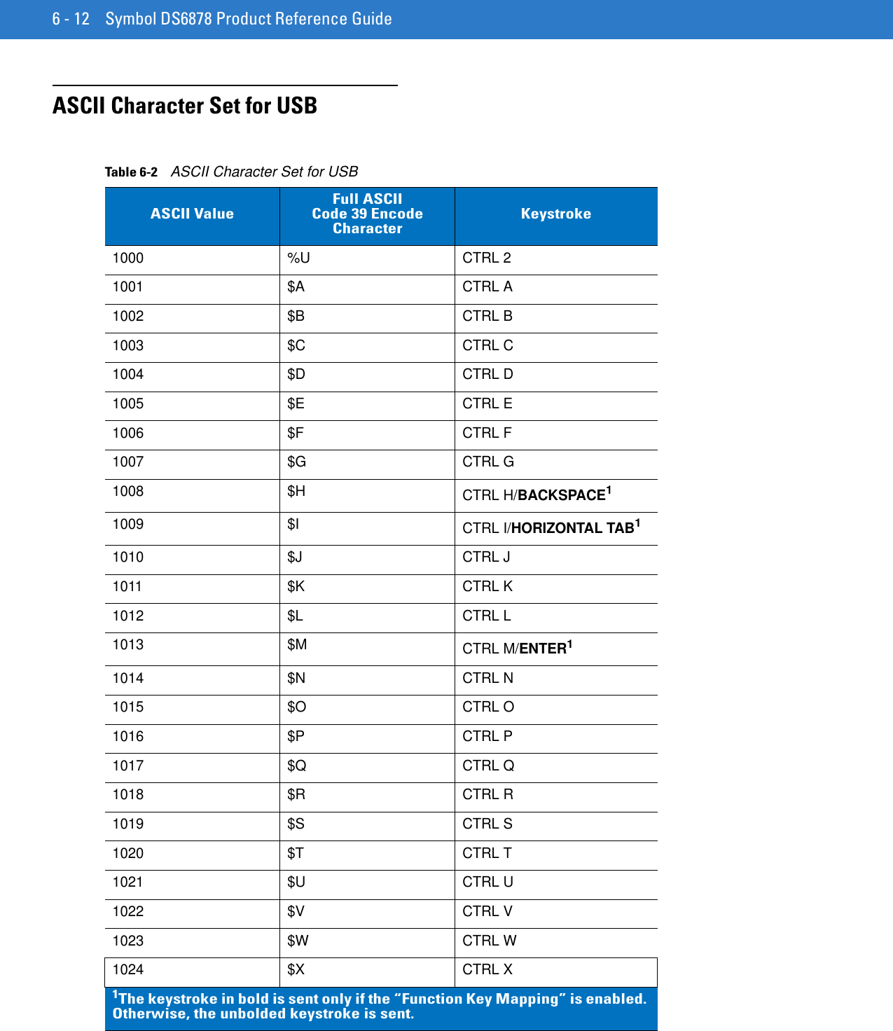
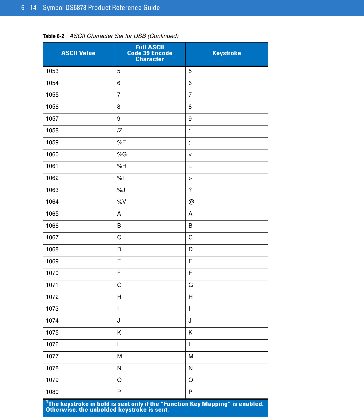
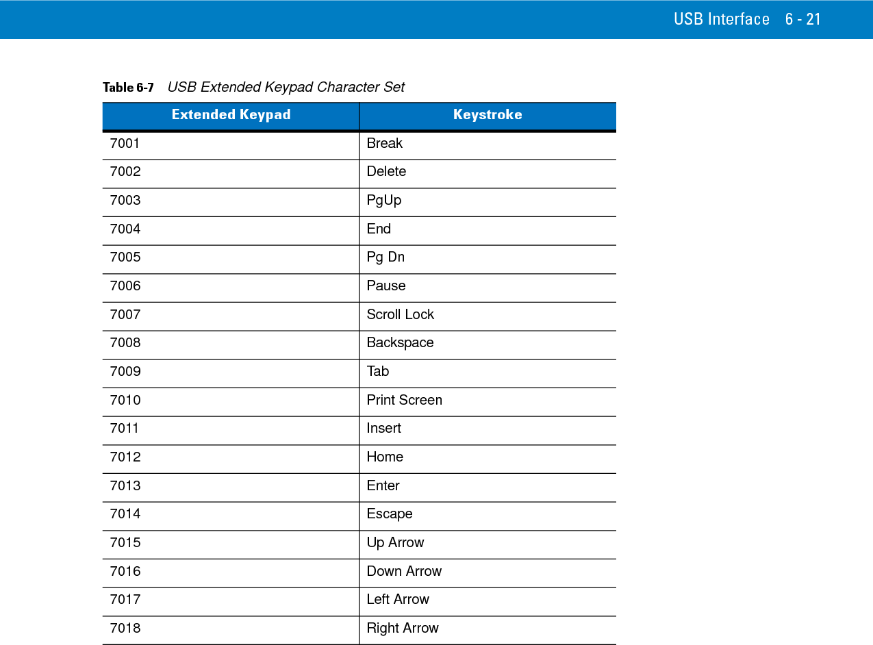
![USB Interface 6 - 131025 $Y CTRL Y1026 $Z CTRL Z1027 %A CTRL [/ESC11028 %B CTRL \1029 %C CTRL ]1030 %D CTRL 61031 %E CTRL -1032 Space Space1033 /A !1034 /B “1035 /C #1036 /D $1037 /E %1038 /F &1039 /G ‘1040 /H (1041 /I )1042 /J *1043 /K +1044 /L ,1045 - -1046 . .1047 /O /1048 0 01049 1 11050 2 21051 3 31052 4 4Table 6-2 ASCII Character Set for USB (Continued)ASCII ValueFull ASCIICode 39 Encode CharacterKeystroke1The keystroke in bold is sent only if the “Function Key Mapping” is enabled. Otherwise, the unbolded keystroke is sent.](https://usermanual.wiki/Zebra-Technologies/DS6878.User-Manual-I/User-Guide-1246132-Page-133.png)
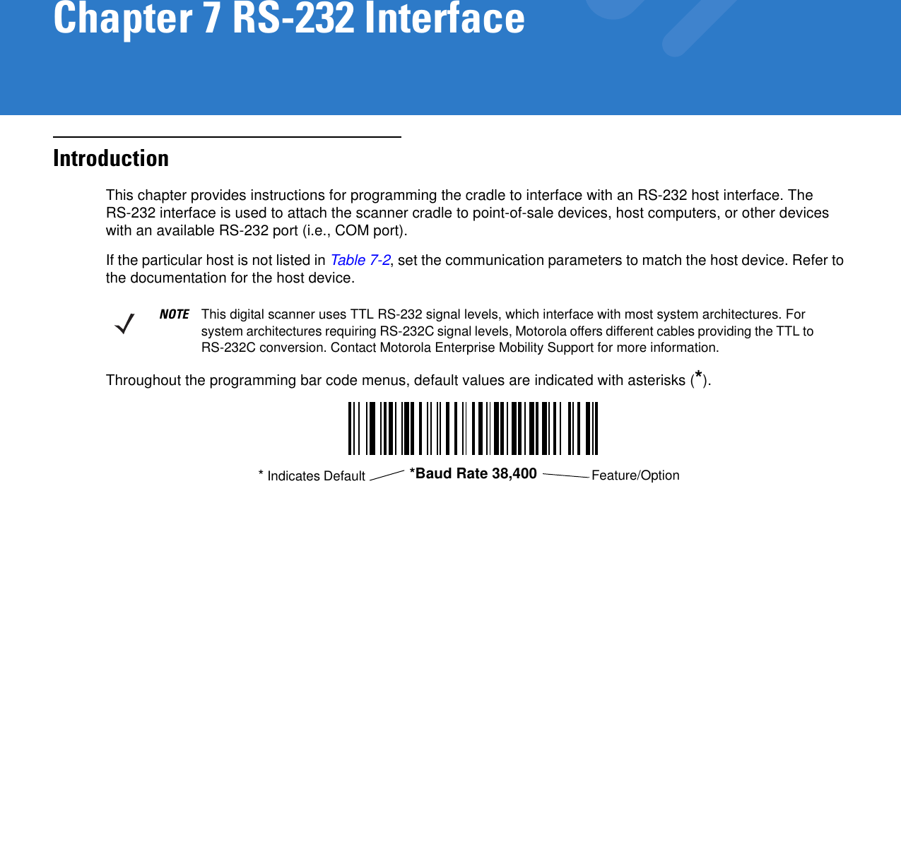
![USB Interface 6 - 151081 Q Q1082 R R1083 S S1084 T T1085 U U1086 V V1087 W W1088 X X1089 Y Y1090 Z Z1091 %K [1092 %L \1093 %M ]1094 %N ^1095 %O _1096 %W `1097 +A a1098 +B b1099 +C c1100 +D d1101 +E e1102 +F f1103 +G g1104 +H h1105 +I i1106 +J j1107 +K k1108 +L lTable 6-2 ASCII Character Set for USB (Continued)ASCII ValueFull ASCIICode 39 Encode CharacterKeystroke1The keystroke in bold is sent only if the “Function Key Mapping” is enabled. Otherwise, the unbolded keystroke is sent.](https://usermanual.wiki/Zebra-Technologies/DS6878.User-Manual-I/User-Guide-1246132-Page-135.png)
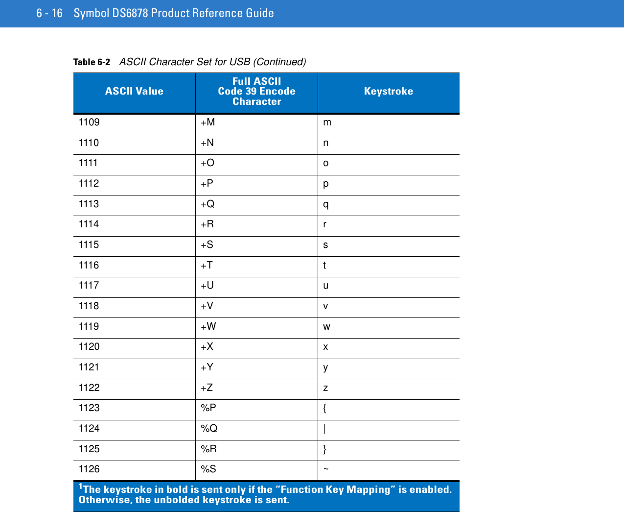
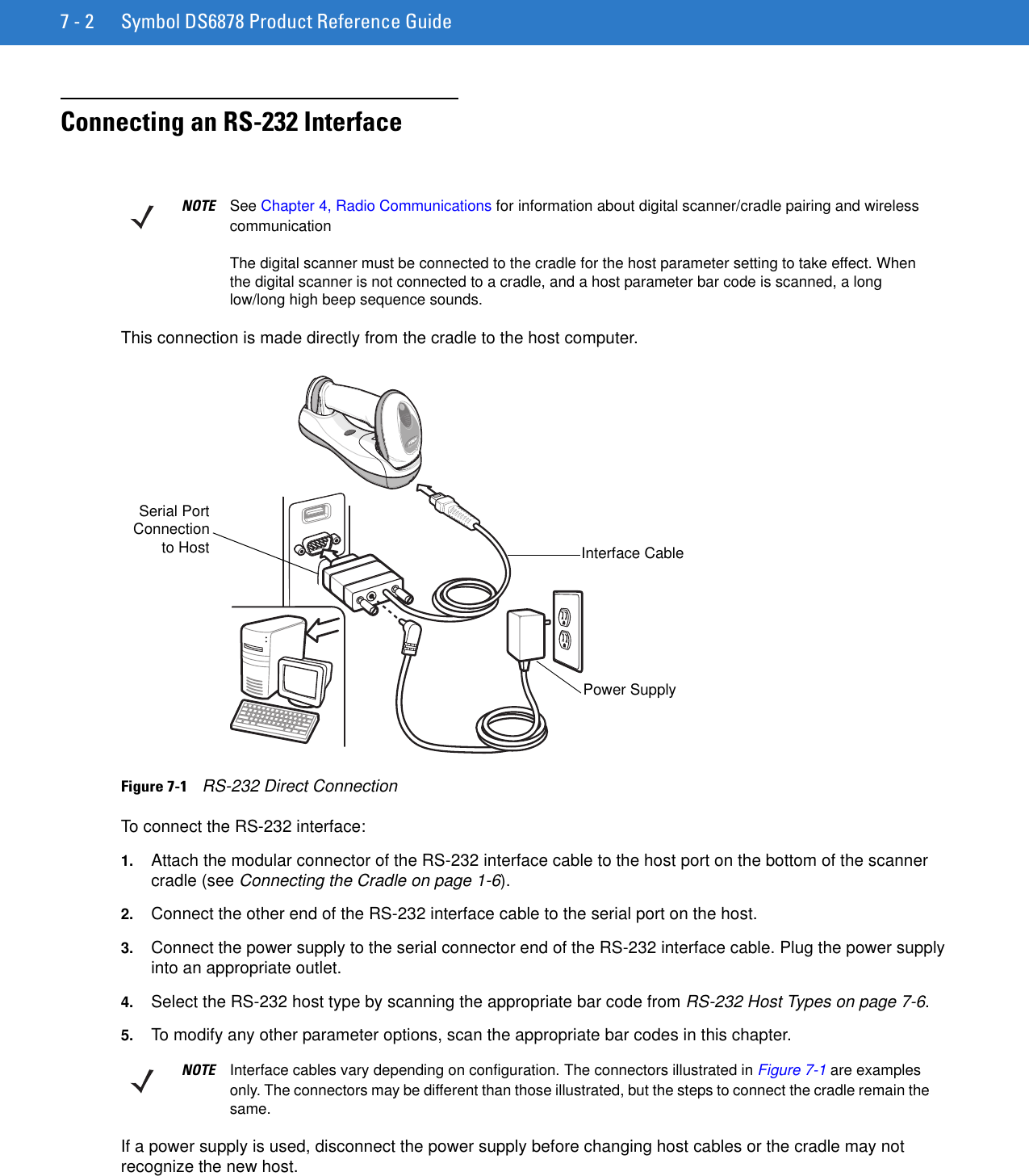
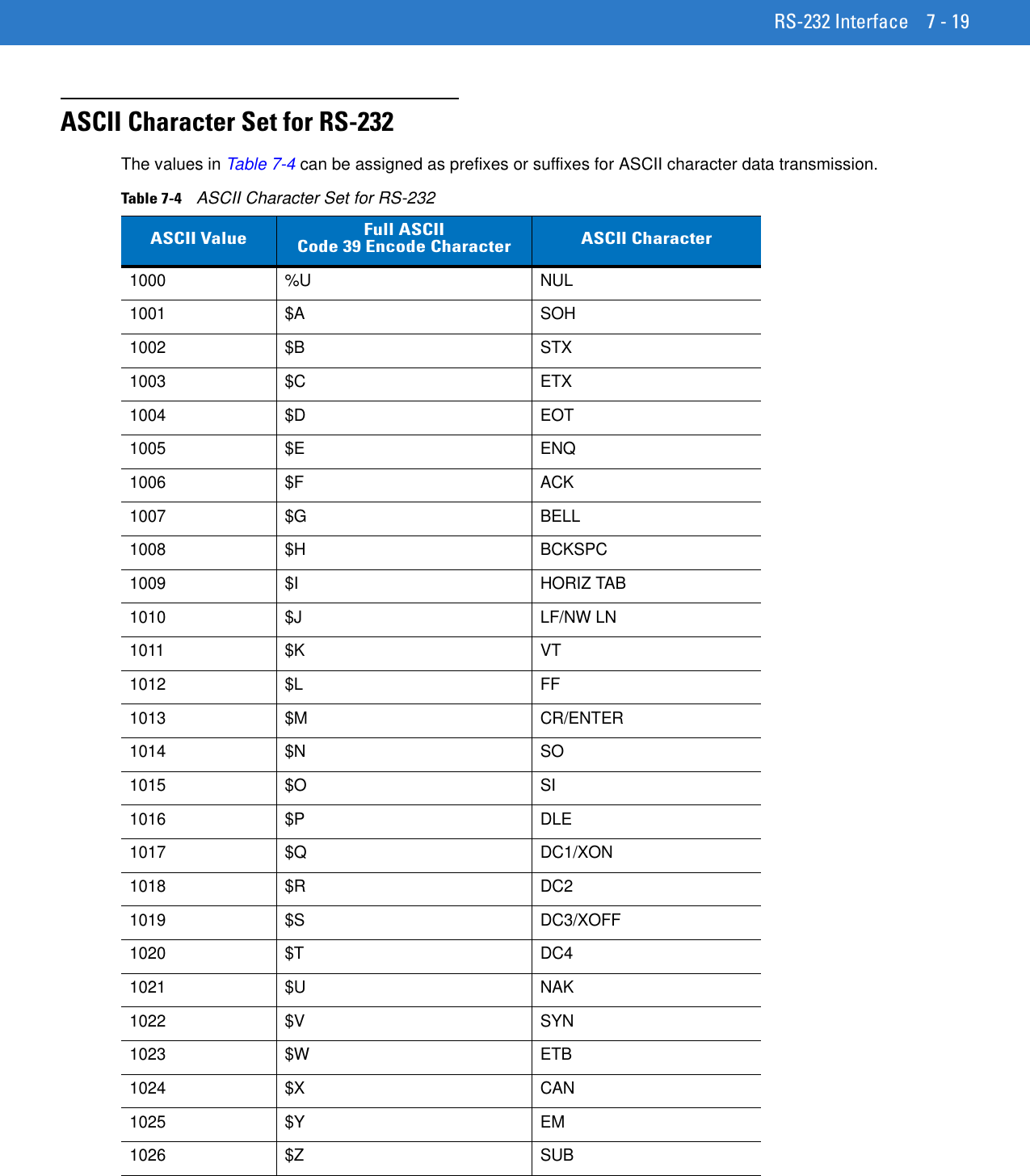
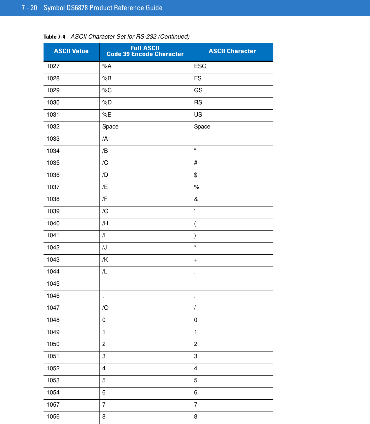
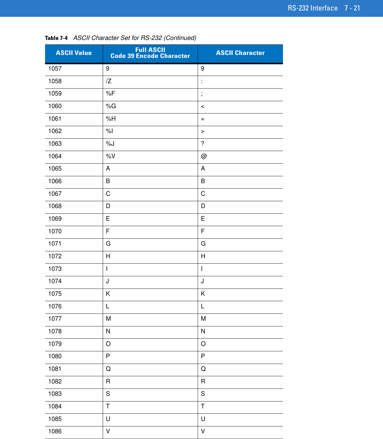
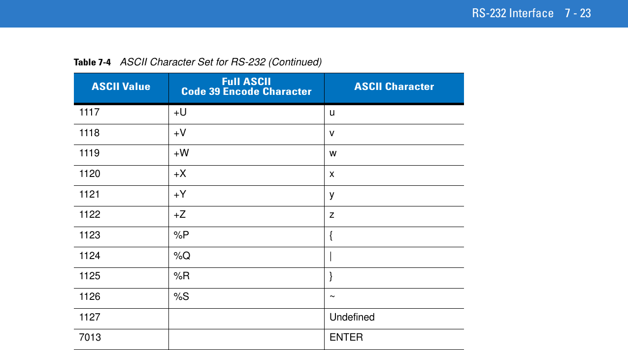
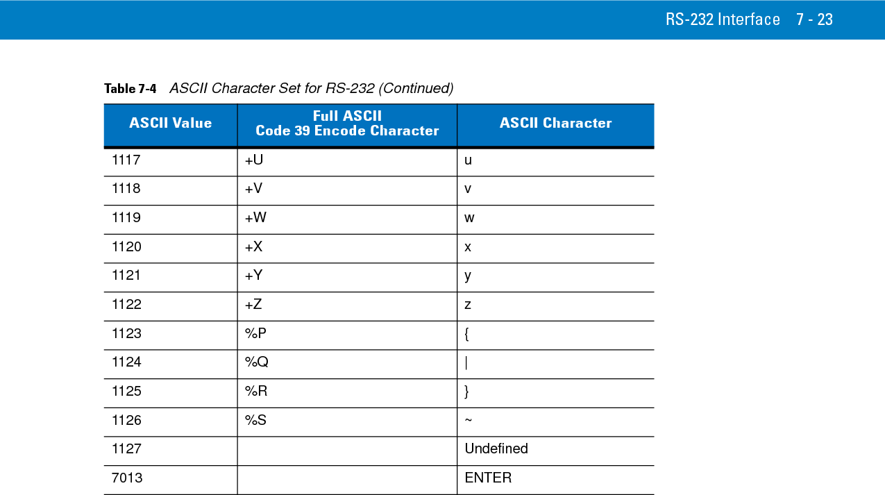
![7 - 22 Symbol DS6878 Product Reference Guide1087 W W1088 X X1089 Y Y1090 Z Z1091 %K [1092 %L \1093 %M ]1094 %N ^1095 %O _1096 %W `1097 +A a1098 +B b1099 +C c1100 +D d1101 +E e1102 +F f1103 +G g1104 +H h1105 +I i1106 +J j1107 +K k1108 +L l1109 +M m1110 +N n1111 +O o1112 +P p1113 +Q q1114 +R r1115 +S s1116 +T tTable 7-4 ASCII Character Set for RS-232 (Continued)ASCII Value Full ASCIICode 39 Encode Character ASCII Character](https://usermanual.wiki/Zebra-Technologies/DS6878.User-Manual-I/User-Guide-1246132-Page-164.png)

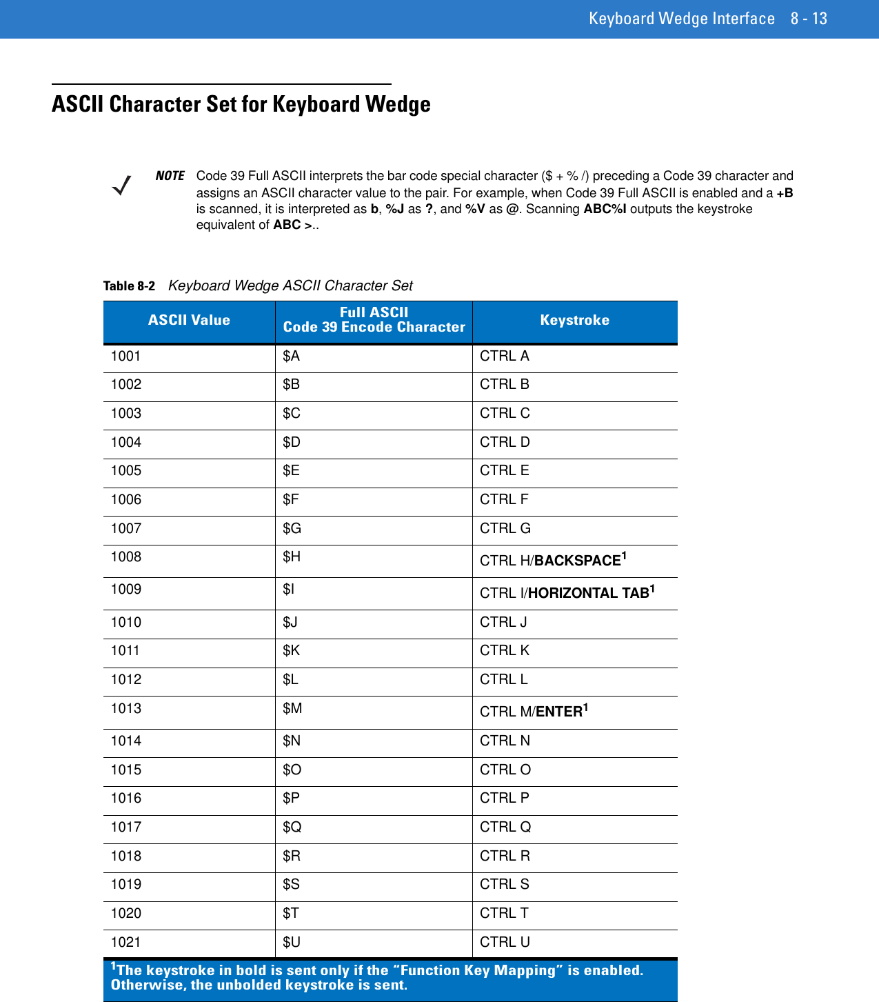
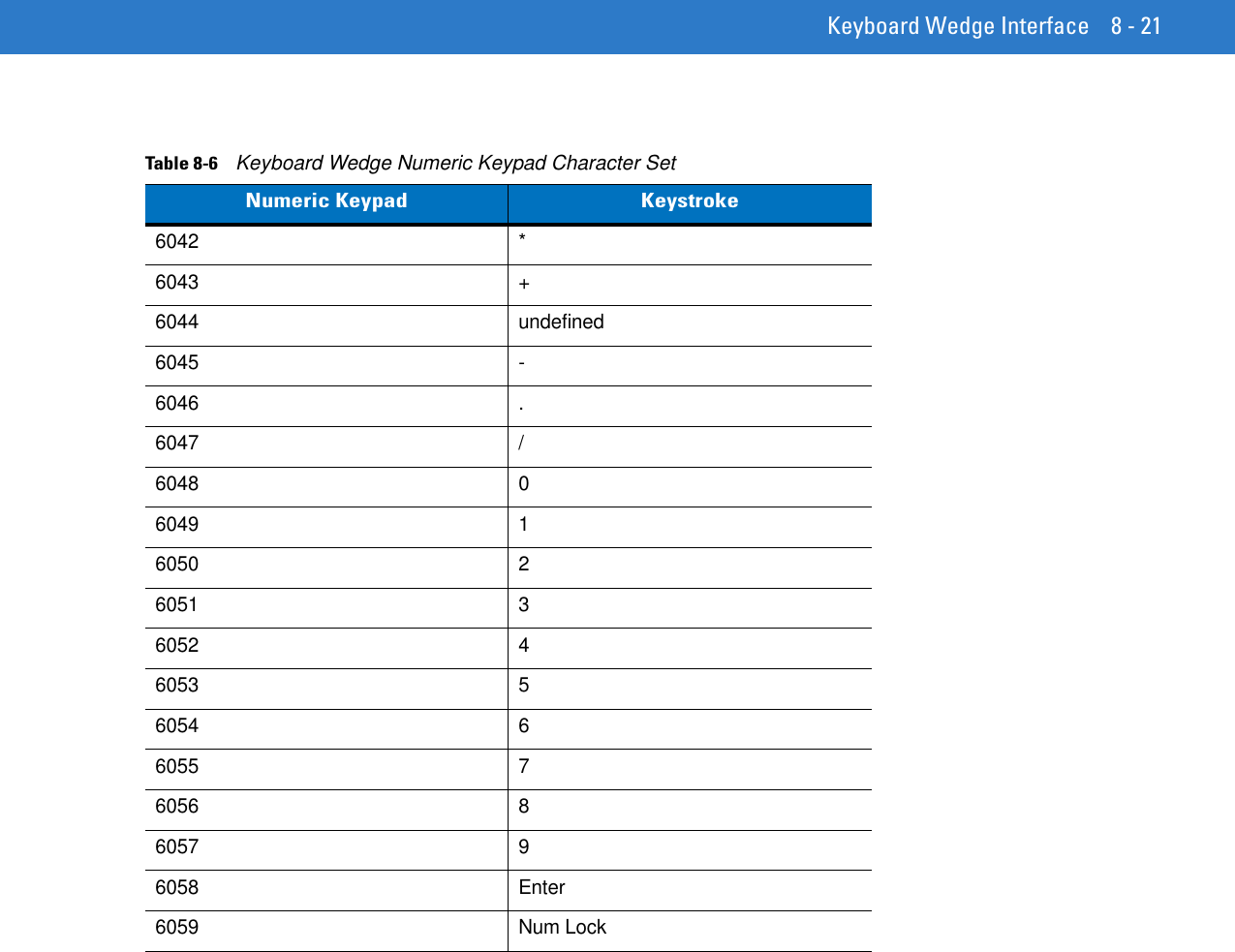
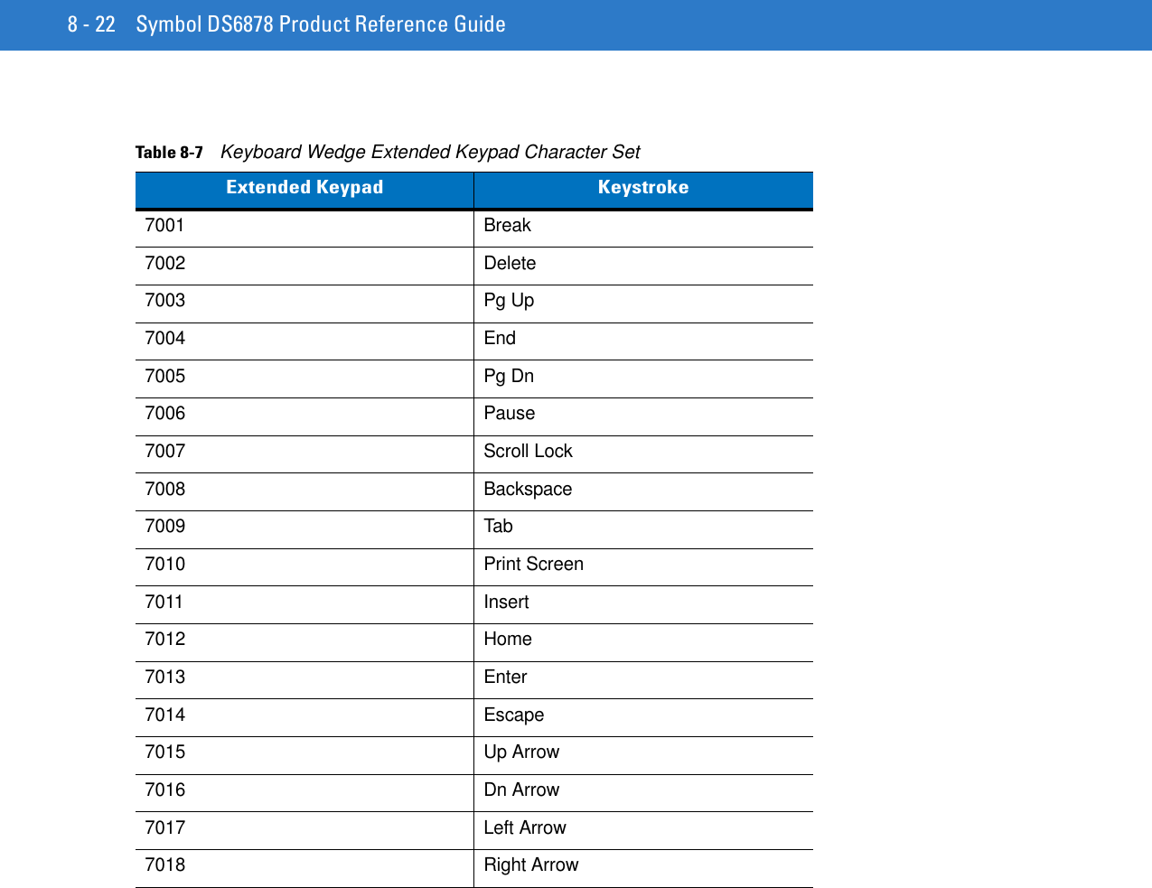
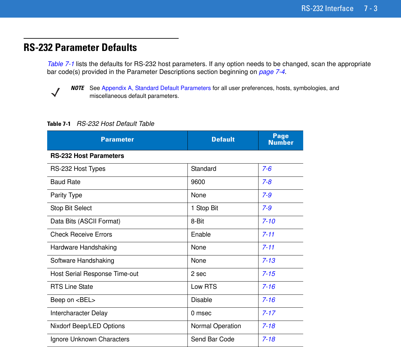
![8 - 14 Symbol DS6878 Product Reference Guide1022 $V CTRL V1023 $W CTRL W1024 $X CTRL X1025 $Y CTRL Y1026 $Z CTRL Z1027 %A CTRL [ /ESC11028 %B CTRL \1029 %C CTRL ]1030 %D CTRL 61031 %E CTRL -1032 Space Space1033 /A !1034 /B “1035 /C #1036 /D $1037 /E %1038 /F &1039 /G ‘1040 /H (1041 /I )1042 /J *1043 /K +1044 /L ,1045 - -1046 . .1047 /O /1048 0 01049 1 1Table 8-2 Keyboard Wedge ASCII Character Set (Continued)ASCII Value Full ASCII Code 39 Encode Character Keystroke1The keystroke in bold is sent only if the “Function Key Mapping” is enabled. Otherwise, the unbolded keystroke is sent.](https://usermanual.wiki/Zebra-Technologies/DS6878.User-Manual-I/User-Guide-1246132-Page-180.png)
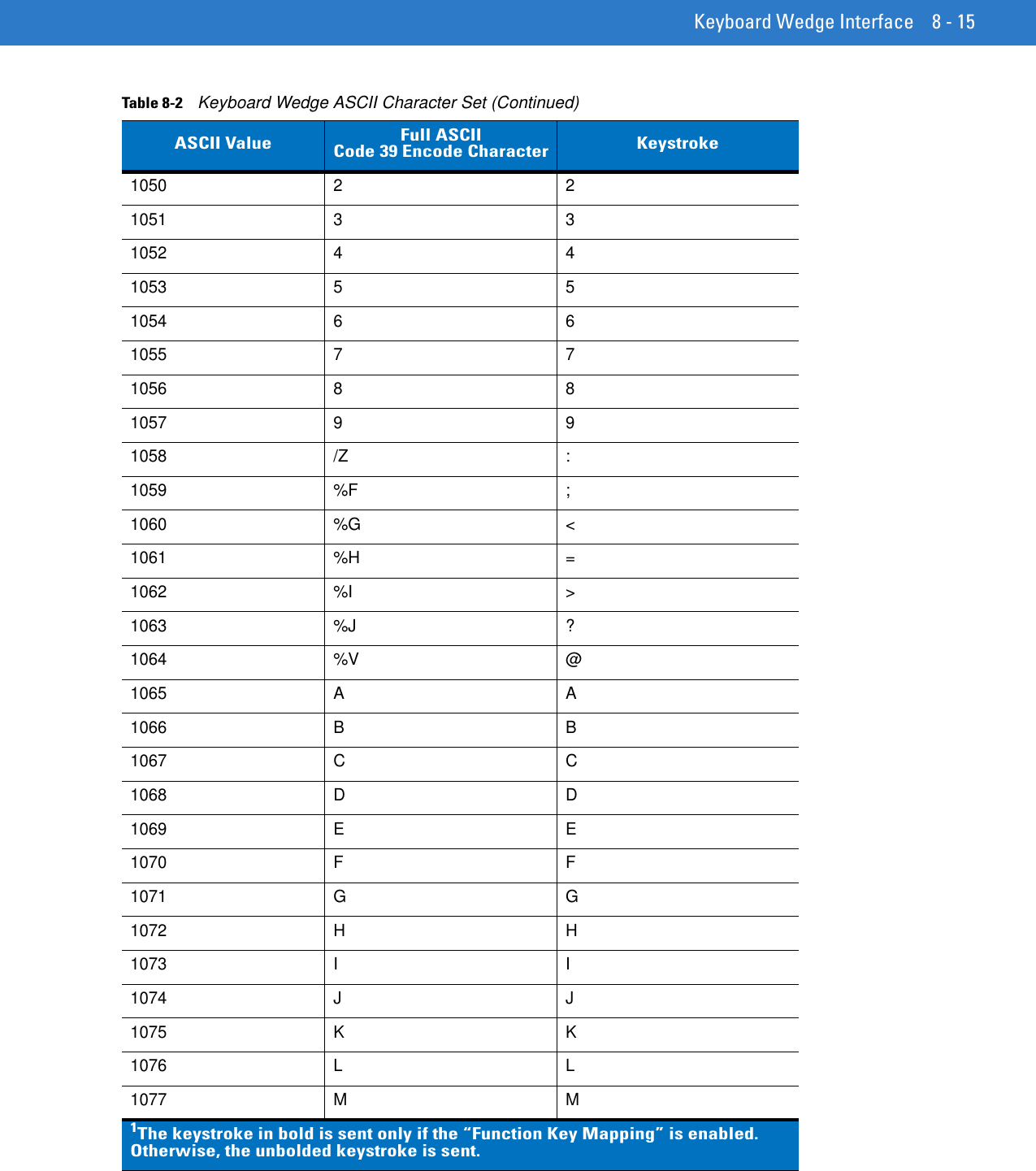
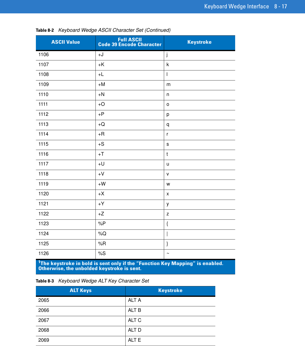
![8 - 16 Symbol DS6878 Product Reference Guide1078 N N1079 O O1080 P P1081 Q Q1082 R R1083 S S1084 T T1085 U U1086 V V1087 W W1088 X X1089 Y Y1090 Z Z1091 %K [1092 %L \1093 %M ]1094 %N ^1095 %O _1096 %W ‘1097 +A a1098 +B b1099 +C c1100 +D d1101 +E e1102 +F f1103 +G g1104 +H h1105 +I iTable 8-2 Keyboard Wedge ASCII Character Set (Continued)ASCII Value Full ASCII Code 39 Encode Character Keystroke1The keystroke in bold is sent only if the “Function Key Mapping” is enabled. Otherwise, the unbolded keystroke is sent.](https://usermanual.wiki/Zebra-Technologies/DS6878.User-Manual-I/User-Guide-1246132-Page-182.png)