Zebra Technologies DS6878 Barcode scanner with integrated Bluetooth User Manual Symbol DS6878 Product Reference Guide
Zebra Technologies Corporation Barcode scanner with integrated Bluetooth Symbol DS6878 Product Reference Guide
Contents
- 1. User Manual II
- 2. User Manual III
- 3. User Manual I
User Manual I
Symbol DS6878
Product Reference Guide

Symbol DS6878
Product Reference Guide
72E-131700-01
Revision A
March 2010

ii Symbol DS6878 Product Reference Guide
© 2009 by Motorola, Inc. All rights reserved.
No part of this publication may be reproduced or used in any form, or by any electrical or mechanical means, without permission in writing
from Motorola. This includes electronic or mechanical means, such as photocopying, recording, or information storage and retrieval
systems. The material in this manual is subject to change without notice.
The software is provided strictly on an “as is” basis. All software, including firmware, furnished to the user is on a licensed basis. Motorola
grants to the user a non-transferable and non-exclusive license to use each software or firmware program delivered hereunder (licensed
program). Except as noted below, such license may not be assigned, sublicensed, or otherwise transferred by the user without prior written
consent of Motorola. No right to copy a licensed program in whole or in part is granted, except as permitted under copyright law. The user
shall not modify, merge, or incorporate any form or portion of a licensed program with other program material, create a derivative work from
a licensed program, or use a licensed program in a network without written permission from Motorola. The user agrees to maintain
Motorola’s copyright notice on the licensed programs delivered hereunder, and to include the same on any authorized copies it makes, in
whole or in part. The user agrees not to decompile, disassemble, decode, or reverse engineer any licensed program delivered to the user
or any portion thereof.
Motorola reserves the right to make changes to any software or product to improve reliability, function, or design.
Motorola does not assume any product liability arising out of, or in connection with, the application or use of any product, circuit, or
application described herein.
No license is granted, either expressly or by implication, estoppel, or otherwise under any Motorola, Inc., intellectual property rights. An
implied license only exists for equipment, circuits, and subsystems contained in Motorola products.
MOTOROLA and the Stylized M Logo and Symbol and the Symbol logo are registered in the US Patent & Trademark Office. Bluetooth is a
registered trademark of Bluetooth SIG. Microsoft, Windows and ActiveSync are either registered trademarks or trademarks of Microsoft
Corporation. All other product or service names are the property of their respective owners.
This media, or Motorola Product, may include Motorola Software, Commercial Third Party Software, and Publicly Available Software.
The Motorola Software that may be included on this media, or included in the Motorola Product, is Copyright (c) by Motorola, Inc., and its
use is subject to the licenses, terms and conditions of the agreement in force between the purchaser of the Motorola Product and
Motorola, Inc.
The Commercial Third Party Software that may be included on this media, or included in the Motorola Product, is subject to the licenses,
terms and conditions of the agreement in force between the purchaser of the Motorola Product and Motorola, Inc., unless a separate
Commercial Third Party Software License is included, in which case, your use of the Commercial Third Party Software will then be
governed by the separate Commercial Third Party License.
The Publicly Available Software that may be included on this media, or in the Motorola Product, is listed below. The use of the listed
Publicly Available Software is subject to the licenses, terms and conditions of the agreement in force between the purchaser of the
Motorola Product and Motorola, Inc., as well as, the terms and conditions of the license of each Publicly Available Software package.
Copies of the licenses for the listed Publicly Available Software, as well as, all attributions, acknowledgements, and software information
details, are included below. Motorola is required to reproduce the software licenses, acknowledgments and copyright notices as provided
by the Authors and Owners, thus, all such information is provided in its native language form, without modification or translation.
The Publicly Available Software in the list below is limited to the Publicly Available Software included by Motorola. The Publicly Available
Software included by Commercial Third Party Software or Products, that is used in the Motorola Product, are disclosed in the Commercial
Third Party Licenses, or via the respective Commercial Third Party Publicly Available Software Legal Notices.
Publicly available software list:
Name: Regular Expression Evaluator
Version: 8.3
Description: Compiles and executes regular expressions
Software Site: http://www.freebsd.org/cgi/cvsweb.cgi/src/lib/libc/regex/
Source Code: No Source Distribution Obligations. Motorola will not provide nor distribute the Source Code for the
Regular Expression Evaluator.
License: BSD Style License
© 1992 Henry Spencer.
© 1992, 1993 The Regents of the University of California. All rights reserved.
This code is derived from software contributed to Berkeley by Henry Spencer of the University of Toronto. Redistribution and use in source
and binary forms, with or without modification, are permitted provided that the following conditions are met:
1. Redistributions of source code must retain the above copyright notice, this list of conditions and the following disclaimer.
2. Redistributions in binary form must reproduce the above copyright notice, this list of conditions and the following disclaimer in the
documentation and/or other materials provided with the distribution.
3. All advertising materials mentioning features or use of this software must display the following acknowledgement:

iii
This product includes software developed by the University of California, Berkeley and its contributors.
4. Neither the name of the University nor the names of its contributors may be used to endorse or promote products derived from this
software without specific prior written permission.
THIS SOFTWARE IS PROVIDED BY THE REGENTS AND CONTRIBUTORS ``AS IS'' AND ANY EXPRESS OR IMPLIED
WARRANTIES, INCLUDING, BUT NOT LIMITED TO, THE IMPLIED WARRANTIES OF MERCHANTABILITY AND FITNESS FOR A
PARTICULAR PURPOSE ARE DISCLAIMED. IN NO EVENT SHALL THE REGENTS OR CONTRIBUTORS BE LIABLE FOR ANY
DIRECT, INDIRECT, INCIDENTAL, SPECIAL, EXEMPLARY, OR CONSEQUENTIAL DAMAGES (INCLUDING, BUT NOT LIMITED TO,
PROCUREMENT OF SUBSTITUTE GOODS OR SERVICES; LOSS OF USE, DATA, OR PROFITS; OR BUSINESS INTERRUPTION)
HOWEVER CAUSED AND ON ANY THEORY OF LIABILITY, WHETHER IN CONTRACT, STRICT LIABILITY, OR TORT (INCLUDING
NEGLIGENCE OR OTHERWISE) ARISING IN ANY WAY OUT OF THE USE OF THIS SOFTWARE, EVEN IF ADVISED OF THE
POSSIBILITY OF SUCH DAMAGE.
Motorola, Inc.
One Motorola Plaza
Holtsville, New York 11742-1300
http://www.motorola.com/enterprisemobility
Patents
This product is covered by one or more of the patents listed on the website:
http://www.motorola.com/enterprisemobility/patents.
Warranty
The complete Motorola hardware product warranty statement is available at:
http://www.motorola.com/enterprisemobility/warranty.
Revision History
Changes to the original manual are listed below:
Change Date Description
-01 Rev A 3/2010 Initial release.

iv Symbol DS6878 Product Reference Guide

Patents........................................................................................................................... iii
Warranty ........................................................................................................................ iii
Revision History............................................................................................................. iii
About This Guide
Introduction.................................................................................................................... xvii
Configurations................................................................................................................ xvii
Chapter Descriptions ..................................................................................................... xvii
Notational Conventions.................................................................................................. xviii
Related Documents ....................................................................................................... xix
Service Information........................................................................................................ xix
Chapter 1: Getting Started
Introduction ................................................................................................................... 1-1
Interfaces ...................................................................................................................... 1-2
Unpacking the Digital Scanner and Cradle ................................................................... 1-2
Parts ............................................................................................................................. 1-3
Scanner ................................................................................................................... 1-3
Cradle ..................................................................................................................... 1-4
Digital Scanner Cradle .................................................................................................. 1-6
Connecting the Cradle ............................................................................................ 1-6
Supplying Power to the Cradle ............................................................................... 1-7
Using the USB Interface to Supply Power ........................................................ 1-7
Lost Connection to Host .......................................................................................... 1-7
Mounting the Cradle ................................................................................................ 1-7
Replacing the Digital Scanner Battery .......................................................................... 1-8
Charging the Digital Scanner Battery ........................................................................... 1-9
Charging LED ......................................................................................................... 1-9
Shutting Off the Digital Scanner Battery ....................................................................... 1-9
Reconditioning the Digital Scanner Battery .................................................................. 1-9
Battery Reconditioning LED Definitions .................................................................. 1-10
Inserting the Digital Scanner in the Cradle ................................................................... 1-10
Table of Contents

vi Symbol DS6878 Product Reference Guide
Horizontal Cradle Mount ......................................................................................... 1-10
Vertical Cradle Mount ............................................................................................. 1-10
Radio Communications ................................................................................................. 1-11
Configuring the Digital Scanner .................................................................................... 1-11
Accessories .................................................................................................................. 1-12
Lanyard ................................................................................................................... 1-12
Chapter 2: Scanning
Introduction ................................................................................................................... 2-1
Beeper Definitions ........................................................................................................ 2-1
LED Definitions ............................................................................................................. 2-3
Scanning ...................................................................................................................... 2-5
Aiming ..................................................................................................................... 2-5
Decode Ranges ............................................................................................................ 2-7
Chapter 3: Maintenance, Troubleshooting & Technical Specifications
Introduction ................................................................................................................... 3-1
Maintenance ................................................................................................................. 3-1
Digital Scanner ........................................................................................................ 3-1
Cradle ..................................................................................................................... 3-2
Battery Information ....................................................................................................... 3-2
Troubleshooting ............................................................................................................ 3-2
Technical Specifications ............................................................................................... 3-7
Cradle Signal Descriptions ........................................................................................... 3-10
Chapter 4: Radio Communications
Introduction ................................................................................................................... 4-1
Scanning Sequence Examples ............................................................................... 4-1
Errors While Scanning ............................................................................................ 4-1
Radio Communications Parameter Defaults ................................................................. 4-2
Wireless Beeper Definitions .......................................................................................... 4-3
Radio Communications Host Types ............................................................................. 4-4
Bluetooth Technology Profile Support .......................................................................... 4-6
Master/Slave Set Up ............................................................................................... 4-6
Master ............................................................................................................... 4-6
Slave ................................................................................................................. 4-6
Bluetooth Friendly Name ........................................................................................ 4-7
Discoverable Mode ................................................................................................. 4-7
HID Host Parameters .................................................................................................... 4-8
HID Country Keyboard Types (Country Codes) ...................................................... 4-8
HID Keyboard Keystroke Delay .............................................................................. 4-10
HID CAPS Lock Override ........................................................................................ 4-10
HID Ignore Unknown Characters ............................................................................ 4-11
Emulate Keypad ...................................................................................................... 4-11
HID Keyboard FN1 Substitution .............................................................................. 4-12
HID Function Key Mapping ..................................................................................... 4-12
Simulated Caps Lock .............................................................................................. 4-13

Table of Contents vii
Convert Case .......................................................................................................... 4-13
Auto-reconnect Feature ................................................................................................ 4-14
Reconnect Attempt Beep Feedback ....................................................................... 4-14
Reconnect Attempt Interval ..................................................................................... 4-15
Auto-reconnect in Bluetooth Keyboard Emulation (HID Slave) Mode ..................... 4-17
Out of Range Indicator .................................................................................................. 4-17
Digital Scanner(s) To Cradle Support ........................................................................... 4-18
Modes of Operation ................................................................................................ 4-18
Point-to-Point Communication .......................................................................... 4-18
Multipoint-to-Point Communication ................................................................... 4-18
Parameter Broadcast (Cradle Host Only) ............................................................... 4-19
Pairing ..................................................................................................................... 4-19
Pairing Modes ................................................................................................... 4-20
Lock Override .................................................................................................... 4-20
Pairing Methods ................................................................................................ 4-21
Unpairing ........................................................................................................... 4-21
Pairing Bar Code Format ........................................................................................ 4-22
Pairing Bar Code Example ................................................................................ 4-22
Connection Maintenance Interval ........................................................................... 4-23
Considerations .................................................................................................. 4-23
Bluetooth Security ......................................................................................................... 4-25
Authentication ......................................................................................................... 4-25
PIN Code ................................................................................................................ 4-26
Variable PIN Code ............................................................................................ 4-26
Encryption ............................................................................................................... 4-27
Chapter 5: User Preferences & Miscellaneous Digital Scanner Options
Introduction ................................................................................................................... 5-1
Scanning Sequence Examples ..................................................................................... 5-2
Errors While Scanning .................................................................................................. 5-2
User Preferences/Miscellaneous Option Parameter Defaults ...................................... 5-2
User Preferences .......................................................................................................... 5-4
Default Parameters ................................................................................................. 5-4
Parameter Bar Code Scanning ............................................................................... 5-5
Beep After Good Decode ........................................................................................ 5-5
Suppress Power Up Beeps ..................................................................................... 5-6
Beeper Tone ........................................................................................................... 5-7
Beeper Volume ....................................................................................................... 5-8
Beeper Duration ...................................................................................................... 5-9
Beep on Insertion .................................................................................................... 5-9
Batch Mode ............................................................................................................. 5-10
Modes of Operation .......................................................................................... 5-10
Low Power Mode .................................................................................................... 5-12
Time Delay to Reduced Power Mode ..................................................................... 5-13
Timeout to Low Power Mode from Auto Aim .......................................................... 5-14
Hand-Held Trigger Mode ........................................................................................ 5-15
Picklist Mode ........................................................................................................... 5-16
Mobile Phone/Display Mode ................................................................................... 5-17
Continuous Bar Code Read .................................................................................... 5-18

viii Symbol DS6878 Product Reference Guide
Unique Bar Code Reporting .................................................................................... 5-18
Decode Session Timeout ........................................................................................ 5-19
Timeout Between Decodes, Same Symbol ............................................................ 5-20
Timeout Between Decodes, Different Symbols ...................................................... 5-20
Fuzzy 1D Processing .............................................................................................. 5-21
Hand-Held Decode Aiming Pattern ......................................................................... 5-22
Decoding Illumination .............................................................................................. 5-23
Multicode Mode ....................................................................................................... 5-23
Multicode Expression .............................................................................................. 5-24
Multicode Expression Syntax ............................................................................ 5-24
Defining Multicode Expression Notes ............................................................... 5-25
Multicode Mode Concatenation .............................................................................. 5-29
Multicode Concatenation Symbology ...................................................................... 5-30
Multicode Troubleshooting ...................................................................................... 5-31
Troubleshooting Multicode Expression Programming ...................................... 5-31
Troubleshooting Multicode Mode Scanning and Decoding ............................... 5-31
Miscellaneous Scanner Parameters ............................................................................. 5-33
Transmit Code ID Character ................................................................................... 5-33
Prefix/Suffix Values ................................................................................................. 5-34
Scan Data Transmission Format ............................................................................ 5-35
FN1 Substitution Values ......................................................................................... 5-36
Transmit “No Read” Message ................................................................................. 5-37
Chapter 6: USB Interface
Introduction ................................................................................................................... 6-1
Connecting a USB Interface ......................................................................................... 6-2
USB Parameter Defaults .............................................................................................. 6-3
USB Host Parameters .................................................................................................. 6-4
USB Device Type .................................................................................................... 6-4
USB Country Keyboard Types (Country Codes) .................................................... 6-5
USB Keystroke Delay ............................................................................................. 6-7
USB CAPS Lock Override ...................................................................................... 6-7
USB Ignore Unknown Characters ........................................................................... 6-8
Emulate Keypad ...................................................................................................... 6-8
USB Keyboard FN 1 Substitution ............................................................................ 6-9
Function Key Mapping ............................................................................................ 6-9
Simulated Caps Lock .............................................................................................. 6-10
Convert Case .......................................................................................................... 6-10
Optional USB Parameters ............................................................................................ 6-11
Ignore Beep ............................................................................................................ 6-11
Ignore Bar Code Configuration ............................................................................... 6-11
ASCII Character Set for USB ........................................................................................ 6-12
Chapter 7: RS-232 Interface
Introduction ................................................................................................................... 7-1
Connecting an RS-232 Interface .................................................................................. 7-2
RS-232 Parameter Defaults .......................................................................................... 7-3
RS-232 Host Parameters .............................................................................................. 7-4

Table of Contents ix
RS-232 Host Types ................................................................................................. 7-6
Baud Rate ............................................................................................................... 7-8
Parity ....................................................................................................................... 7-9
Stop Bit Select ........................................................................................................ 7-9
Data Bits (ASCII Format) ........................................................................................ 7-10
Check Receive Errors ............................................................................................. 7-11
Hardware Handshaking .......................................................................................... 7-11
Software Handshaking ............................................................................................ 7-13
Host Serial Response Time-out .............................................................................. 7-15
RTS Line State ........................................................................................................ 7-16
Beep on <BEL> ....................................................................................................... 7-16
Intercharacter Delay ................................................................................................ 7-17
Nixdorf Beep/LED Options ...................................................................................... 7-18
Ignore Unknown Characters ................................................................................... 7-18
ASCII Character Set for RS-232 ................................................................................... 7-19
Chapter 8: Keyboard Wedge Interface
Introduction ................................................................................................................... 8-1
Connecting a Keyboard Wedge Interface ..................................................................... 8-2
Keyboard Wedge Parameter Defaults .......................................................................... 8-3
Keyboard Wedge Host Parameters .............................................................................. 8-4
Keyboard Wedge Host Types ................................................................................. 8-4
Keyboard Wedge Country Types (Country Codes) ................................................ 8-5
Ignore Unknown Characters ................................................................................... 8-6
Keystroke Delay ...................................................................................................... 8-7
Intra-Keystroke Delay ............................................................................................. 8-7
Alternate Numeric Keypad Emulation ..................................................................... 8-8
Caps Lock On ......................................................................................................... 8-8
Caps Lock Override ................................................................................................ 8-9
Convert Wedge Data .............................................................................................. 8-9
Function Key Mapping ............................................................................................ 8-10
FN1 Substitution ..................................................................................................... 8-10
Send Make and Break ............................................................................................ 8-11
Keyboard Maps ............................................................................................................. 8-12
ASCII Character Set for Keyboard Wedge ................................................................... 8-13
Chapter 9: IBM Interface
Introduction ................................................................................................................... 9-1
Connecting to an IBM 468X/469X Host ........................................................................ 9-2
IBM Parameter Defaults ............................................................................................... 9-3
IBM 468X/469X Host Parameters ................................................................................. 9-4
Port Address ........................................................................................................... 9-4
Convert Unknown to Code 39 ................................................................................. 9-5
Optional IBM Parameters ............................................................................................. 9-5
Ignore Beep ............................................................................................................ 9-5
Ignore Bar Code Configuration ............................................................................... 9-6

x Symbol DS6878 Product Reference Guide
Chapter 10: Wand Emulation Interface
Introduction ................................................................................................................... 10-1
Connecting Using Wand Emulation .............................................................................. 10-2
Wand Emulation Parameter Defaults ........................................................................... 10-3
Wand Emulation Host Parameters ............................................................................... 10-4
Wand Emulation Host Types .................................................................................. 10-4
Leading Margin (Quiet Zone) .................................................................................. 10-5
Polarity .................................................................................................................... 10-6
Ignore Unknown Characters ................................................................................... 10-6
Convert All Bar Codes to Code 39 .......................................................................... 10-7
Convert Code 39 to Full ASCII ............................................................................... 10-8
Chapter 11: Scanner Emulation Interface
Connecting Using Scanner Emulation .......................................................................... 11-2
Scanner Emulation Parameter Defaults ....................................................................... 11-3
Scanner Emulation Host ............................................................................................... 11-3
Scanner Emulation Host Parameters ........................................................................... 11-4
Beep Style ............................................................................................................... 11-4
Parameter Pass-Through ........................................................................................ 11-5
Convert Newer Code Types .................................................................................... 11-6
Module Width .......................................................................................................... 11-6
Convert All Bar Codes to Code 39 .......................................................................... 11-7
Code 39 Full ASCII Conversion .............................................................................. 11-7
Transmission Timeout ............................................................................................. 11-8
Ignore Unknown Characters ................................................................................... 11-9
Leading Margin ....................................................................................................... 11-9
Check For Decode LED .......................................................................................... 11-10
Chapter 12: 123Scan2
Introduction ................................................................................................................... 12-1
Communication with 123Scan2 .................................................................................... 12-1
123Scan2 Requirements .............................................................................................. 12-1
Chapter 13: OCR Programming
Introduction ................................................................................................................... 13-1
OCR Parameter Defaults .............................................................................................. 13-2
OCR Programming Parameters .................................................................................... 13-3
Enable/Disable OCR-A ........................................................................................... 13-3
OCR-A Variant ........................................................................................................ 13-3
Enable/Disable OCR-B ........................................................................................... 13-5
OCR-B Variant ........................................................................................................ 13-6
Enable/Disable MICR E13B .................................................................................... 13-9
Enable/Disable US Currency Serial Number .......................................................... 13-10
OCR Orientation ..................................................................................................... 13-10
OCR Lines .............................................................................................................. 13-12
OCR Minimum Characters ...................................................................................... 13-12
OCR Maximum Characters ..................................................................................... 13-13

Table of Contents xi
OCR Security Level ................................................................................................ 13-13
OCR Subset ............................................................................................................ 13-14
OCR Quiet Zone ..................................................................................................... 13-14
OCR Bright Illumination .......................................................................................... 13-15
OCR Template ........................................................................................................ 13-16
Required Digit (9) ............................................................................................. 13-16
Required Alpha (A) .......................................................................................... 13-16
Optional Alphanumeric (1) ............................................................................... 13-17
Optional Alpha (2) ............................................................................................ 13-17
Alpha or Digit (3) .............................................................................................. 13-17
Any Including Space & Reject (4) .................................................................... 13-18
Any except Space & Reject (5) ........................................................................ 13-18
Optional Digit (7) .............................................................................................. 13-18
Digit or Fill (8) ................................................................................................... 13-19
Alpha or Fill (F) ................................................................................................ 13-19
Required Space ( ) ........................................................................................... 13-19
Optional Small Special (.) ................................................................................ 13-20
Other Template Operators ................................................................................ 13-20
Repeat Previous (R) ......................................................................................... 13-24
Template Examples .......................................................................................... 13-25
OCR Check Digit Modulus ...................................................................................... 13-25
OCR Check Digit Multiplier ..................................................................................... 13-26
OCR Check Digit Validation .................................................................................... 13-27
None ................................................................................................................. 13-27
Product Add Left to Right .................................................................................. 13-27
Product Add Right to Left .................................................................................. 13-28
Digit Add Left to Right ....................................................................................... 13-28
Digit Add Right to Left ....................................................................................... 13-29
Product Add Right to Left Simple Remainder ................................................... 13-30
Digit Add Right To Left Simple Remainder ....................................................... 13-31
Health Industry - HIBCC43 ............................................................................... 13-31
Chapter 14: Symbologies
Introduction ................................................................................................................... 14-1
Scanning Sequence Examples ..................................................................................... 14-1
Errors While Scanning .................................................................................................. 14-2
Symbology Parameter Defaults .................................................................................... 14-2
UPC/EAN ...................................................................................................................... 14-7
Enable/Disable UPC-A ............................................................................................ 14-7
Enable/Disable UPC-E ............................................................................................ 14-7
Enable/Disable UPC-E1 .......................................................................................... 14-8
Enable/Disable EAN-8/JAN-8 ................................................................................. 14-8
Enable/Disable EAN-13/JAN-13 ............................................................................. 14-9
Enable/Disable Bookland EAN ............................................................................... 14-9
Decode UPC/EAN/JAN Supplementals .................................................................. 14-10
User-Programmable Supplementals ....................................................................... 14-13
UPC/EAN/JAN Supplemental Redundancy ............................................................ 14-13
UPC/EAN/JAN Supplemental AIM ID Format ......................................................... 14-14
Transmit UPC-A Check Digit .................................................................................. 14-14

xii Symbol DS6878 Product Reference Guide
Transmit UPC-E Check Digit .................................................................................. 14-15
Transmit UPC-E1 Check Digit ................................................................................ 14-15
UPC-A Preamble .................................................................................................... 14-16
UPC-E Preamble .................................................................................................... 14-17
UPC-E1 Preamble .................................................................................................. 14-18
Convert UPC-E to UPC-A ....................................................................................... 14-19
Convert UPC-E1 to UPC-A ..................................................................................... 14-19
EAN-8/JAN-8 Extend .............................................................................................. 14-20
Bookland ISBN Format ........................................................................................... 14-21
UCC Coupon Extended Code ................................................................................. 14-22
ISSN EAN ............................................................................................................... 14-22
Code 128 ...................................................................................................................... 14-23
Enable/Disable Code 128 ....................................................................................... 14-23
Set Lengths for Code 128 ....................................................................................... 14-23
Enable/Disable GS1-128 (formerly UCC/EAN-128) ................................................ 14-24
Enable/Disable ISBT 128 ........................................................................................ 14-25
ISBT Concatenation ................................................................................................ 14-26
Check ISBT Table ................................................................................................... 14-27
ISBT Concatenation Redundancy ........................................................................... 14-27
Code 39 ........................................................................................................................ 14-28
Enable/Disable Code 39 ......................................................................................... 14-28
Enable/Disable Trioptic Code 39 ............................................................................ 14-28
Convert Code 39 to Code 32 .................................................................................. 14-29
Code 32 Prefix ........................................................................................................ 14-29
Set Lengths for Code 39 ......................................................................................... 14-30
Code 39 Check Digit Verification ............................................................................ 14-31
Transmit Code 39 Check Digit ................................................................................ 14-31
Code 39 Full ASCII Conversion .............................................................................. 14-32
Code 39 Buffering - Scan & Store ........................................................................... 14-32
Buffer Data ........................................................................................................ 14-33
Clear Transmission Buffer ................................................................................ 14-33
Transmit Buffer ................................................................................................. 14-34
Overfilling Transmission Buffer ......................................................................... 14-34
Attempt to Transmit an Empty Buffer ................................................................ 14-34
Code 93 ........................................................................................................................ 14-35
Enable/Disable Code 93 ......................................................................................... 14-35
Set Lengths for Code 93 ......................................................................................... 14-35
Code 11 ........................................................................................................................ 14-37
Code 11 .................................................................................................................. 14-37
Set Lengths for Code 11 ......................................................................................... 14-37
Code 11 Check Digit Verification ............................................................................ 14-39
Transmit Code 11 Check Digits .............................................................................. 14-40
Interleaved 2 of 5 (ITF) ................................................................................................. 14-40
Enable/Disable Interleaved 2 of 5 ........................................................................... 14-40
Set Lengths for Interleaved 2 of 5 ........................................................................... 14-41
I 2 of 5 Check Digit Verification ............................................................................... 14-43
Transmit I 2 of 5 Check Digit ................................................................................... 14-43
Convert I 2 of 5 to EAN-13 ...................................................................................... 14-44
Discrete 2 of 5 (DTF) .................................................................................................... 14-44
Enable/Disable Discrete 2 of 5 ................................................................................ 14-44

Table of Contents xiii
Set Lengths for Discrete 2 of 5 ............................................................................... 14-45
Codabar (NW - 7) ......................................................................................................... 14-47
Enable/Disable Codabar ......................................................................................... 14-47
Set Lengths for Codabar ......................................................................................... 14-47
CLSI Editing ............................................................................................................ 14-49
NOTIS Editing ......................................................................................................... 14-49
MSI ............................................................................................................................... 14-50
Enable/Disable MSI ................................................................................................ 14-50
Set Lengths for MSI ................................................................................................ 14-50
MSI Check Digits .................................................................................................... 14-52
Transmit MSI Check Digit(s) ................................................................................... 14-52
MSI Check Digit Algorithm ...................................................................................... 14-53
Chinese 2 of 5 ............................................................................................................... 14-53
Enable/Disable Chinese 2 of 5 ................................................................................ 14-53
Matrix 2 of 5 .................................................................................................................. 14-54
Enable/Disable Matrix 2 of 5 ................................................................................... 14-54
Set Lengths for Matrix 2 of 5 ................................................................................... 14-55
Matrix 2 of 5 Redundancy ....................................................................................... 14-56
Matrix 2 of 5 Check Digit ......................................................................................... 14-56
Transmit Matrix 2 of 5 Check Digit .......................................................................... 14-57
Korean 3 of 5 ................................................................................................................ 14-57
Enable/Disable Korean 3 of 5 ................................................................................. 14-57
Inverse 1D .................................................................................................................... 14-58
Postal Codes ................................................................................................................ 14-59
US Postnet .............................................................................................................. 14-59
US Planet ................................................................................................................ 14-59
Transmit US Postal Check Digit .............................................................................. 14-60
UK Postal ................................................................................................................ 14-60
Transmit UK Postal Check Digit .............................................................................. 14-61
Japan Postal ........................................................................................................... 14-61
Australian Postal ..................................................................................................... 14-62
Netherlands KIX Code ........................................................................................... 14-62
USPS 4CB/One Code/Intelligent Mail ..................................................................... 14-63
UPU FICS Postal .................................................................................................... 14-63
GS1 DataBar ................................................................................................................ 14-64
GS1 DataBar-14 ..................................................................................................... 14-64
GS1 DataBar Limited .............................................................................................. 14-64
GS1 DataBar Expanded ......................................................................................... 14-65
Convert GS1 DataBar to UPC/EAN ........................................................................ 14-65
Composite ..................................................................................................................... 14-66
Composite CC-C ..................................................................................................... 14-66
Composite CC-A/B .................................................................................................. 14-66
Composite TLC-39 .................................................................................................. 14-67
UPC Composite Mode ............................................................................................ 14-67
Composite Beep Mode ........................................................................................... 14-68
GS1-128 Emulation Mode for UCC/EAN Composite Codes ................................... 14-68
2D Symbologies ............................................................................................................ 14-69
Enable/Disable PDF417 .......................................................................................... 14-69
Enable/Disable MicroPDF417 ................................................................................. 14-69
Code 128 Emulation ............................................................................................... 14-70

xiv Symbol DS6878 Product Reference Guide
Data Matrix .............................................................................................................. 14-71
Data Matrix Inverse ................................................................................................. 14-71
Maxicode ................................................................................................................. 14-72
QR Code ................................................................................................................. 14-72
QR Inverse .............................................................................................................. 14-73
MicroQR .................................................................................................................. 14-73
Aztec ....................................................................................................................... 14-74
Aztec Inverse .......................................................................................................... 14-74
Redundancy Level ........................................................................................................ 14-75
Redundancy Level 1 ............................................................................................... 14-75
Redundancy Level 2 ............................................................................................... 14-75
Redundancy Level 3 ............................................................................................... 14-75
Redundancy Level 4 ............................................................................................... 14-76
Security Level ............................................................................................................... 14-77
Intercharacter Gap Size .......................................................................................... 14-78
Report Version .............................................................................................................. 14-78
Macro PDF Features .................................................................................................... 14-79
Flush Macro Buffer .................................................................................................. 14-79
Abort Macro PDF Entry ........................................................................................... 14-79
Chapter 15: Advanced Data Formatting
Introduction ................................................................................................................... 15-1
Rules: Criteria Linked to Actions ................................................................................... 15-1
Using ADF Bar Codes .................................................................................................. 15-2
ADF Bar Code Menu Example ..................................................................................... 15-2
Rule 1: The Code 128 Scanning Rule .................................................................... 15-3
Rule 2: The UPC Scanning Rule ............................................................................ 15-3
Alternate Rule Sets ................................................................................................. 15-3
Rules Hierarchy (in Bar Codes) .............................................................................. 15-4
Default Rules .......................................................................................................... 15-5
ADF Bar Codes ............................................................................................................. 15-6
Special Commands ....................................................................................................... 15-8
Pause Duration ....................................................................................................... 15-8
Begin New Rule ...................................................................................................... 15-8
Save Rule ............................................................................................................... 15-8
Erase ....................................................................................................................... 15-9
Quit Entering Rules ................................................................................................. 15-9
Disable Rule Set ..................................................................................................... 15-10
Criteria .......................................................................................................................... 15-11
Code Types ............................................................................................................. 15-11
Code Lengths .......................................................................................................... 15-15
Message Containing A Specific Data String ........................................................... 15-19
Specific String at Start ...................................................................................... 15-19
Specific String, Any Location ............................................................................ 15-20
Any Message OK .............................................................................................. 15-20
Numeric Keypad ............................................................................................... 15-21
Rule Belongs To Set ......................................................................................... 15-23
Actions .......................................................................................................................... 15-24
Send Data ............................................................................................................... 15-24

Table of Contents xv
Setup Field(s) .......................................................................................................... 15-27
Move Cursor ..................................................................................................... 15-28
Send Pause ...................................................................................................... 15-28
Skip Ahead ........................................................................................................ 15-29
Skip Back ......................................................................................................... 15-30
Send Preset Value ............................................................................................ 15-32
Modify Data ............................................................................................................. 15-32
Remove All Spaces ........................................................................................... 15-32
Crunch All Spaces ............................................................................................ 15-32
Stop Space Removal ........................................................................................ 15-32
Remove Leading Zeros ..................................................................................... 15-33
Stop Zero Removal ........................................................................................... 15-33
Pad Data with Spaces ............................................................................................. 15-34
Pad Data with Zeros ............................................................................................... 15-38
Beeps ...................................................................................................................... 15-43
Send Keystroke (Control Characters and Keyboard Characters) ........................... 15-43
Control Characters ............................................................................................ 15-43
Keyboard Characters ........................................................................................ 15-48
Send ALT Characters ....................................................................................... 15-61
Send Keypad Characters .................................................................................. 15-67
Send Function Key ............................................................................................ 15-72
Send Right Control Key .......................................................................................... 15-79
Send Graphic User Interface (GUI) Characters ...................................................... 15-80
Turn On/Off Rule Sets ............................................................................................ 15-85
Alphanumeric Keyboard ............................................................................................... 15-87
Chapter 16: Driver’s License Set Up (DS6878-DL)
Introduction ................................................................................................................... 16-1
Driver’s License Parsing ............................................................................................... 16-2
Parsing Driver’s License Data Fields (Embedded Driver's License Parsing) ............... 16-3
Embedded Driver's License Parsing Criteria - Code Type ..................................... 16-3
Driver’s License Parse Field Bar Codes ................................................................. 16-4
AAMVA Parse Field Bar Codes .............................................................................. 16-7
Parsing Rule Example .................................................................................................. 16-17
Embedded Driver's License Parsing ADF Example ................................................ 16-21
Field Update Procedure ................................................................................................ 16-23
User Preferences .......................................................................................................... 16-24
Set Default Parameter ............................................................................................ 16-24
Send Keystroke (Control Characters and Keyboard Characters) ........................... 16-24
Control Characters ............................................................................................ 16-24
Keyboard Characters ........................................................................................ 16-29
Appendix A: Standard Default Parameters
Appendix B: Programming Reference
Symbol Code Identifiers ................................................................................................ B-1
AIM Code Identifiers ..................................................................................................... B-3

xvi Symbol DS6878 Product Reference Guide
Appendix C: Sample Bar Codes
Code 39 ........................................................................................................................ C-1
UPC/EAN ...................................................................................................................... C-1
UPC-A, 100% .......................................................................................................... C-1
EAN-13, 100% ........................................................................................................ C-2
Code 128 ...................................................................................................................... C-2
Interleaved 2 of 5 .......................................................................................................... C-2
GS1 DataBar ................................................................................................................ C-3
GS1 DataBar-14 ..................................................................................................... C-4
PDF417 ......................................................................................................................... C-4
Data Matrix ................................................................................................................... C-4
Maxicode ...................................................................................................................... C-5
QR Code ....................................................................................................................... C-5
US Postnet .................................................................................................................... C-5
UK Postal ...................................................................................................................... C-5
Appendix D: Numeric Bar Codes
Numeric Bar Codes ...................................................................................................... D-2
Cancel ........................................................................................................................... D-3
Appendix E: Alphanumeric Bar Codes
Alphanumeric Keyboard ............................................................................................... E-1
Appendix F: ASCII Character Sets
Glossary
Index
Tell Us What You Think...

About This Guide
Introduction
The Symbol DS6878 Product Reference Guide provides general instructions for setting up, operating, maintaining,
and troubleshooting the Symbol DS6878 digital scanner and cradles.
Configurations
This guide includes the following configurations:
•
DS6878-SR20001WR - DS6878 digital scanner, standard range, cash register white
•
DS6878-SR20007WR - DS6878 digital scanner, standard range, twilight black
•
DS6878-HC2000BWR - DS6878 digital scanner, standard range, healthcare white
•
DS6878-DL20001WR - DS6878 digital scanner, standard range, DL parsing, cash register white
•
DS6878-DL20007WR - DS6878 digital scanner, standard range, DL parsing, twilight black
•
DS6878-HD20007WR - DS6878 digital scanner, high density, twilight black
Chapter Descriptions
Topics covered in this guide are as follows:
•
Chapter 1, Getting Started provides a product overview, unpacking instructions, and cable connection
information.
•
Chapter 2, Scanning describes parts of the digital scanner, beeper and LED definitions, and how to use the
digital scanner.
•
Chapter 3, Maintenance, Troubleshooting & Technical Specifications provides information on how to care for
the digital scanner and cradle, troubleshooting, and technical specifications.
•
Chapter 4, Radio Communications provides information about the modes of operation and features available
for wireless communication. This chapter also includes programming bar codes to configure the digital
scanner.

xviii Symbol DS6878 Product Reference Guide
•
Chapter 5, User Preferences & Miscellaneous Digital Scanner Options provides programming bar codes for
selecting user preference features for the digital scanner and commonly used bar codes to customize how
the data is transmitted to the host device.
•
Chapter 6, USB Interface provides information for setting up the digital scanner and cradle for USB
operation.
•
Chapter 7, RS-232 Interface provides information for setting up the digital scanner and cradle for RS-232
operation.
•
Chapter 8, Keyboard Wedge Interface provides information for setting up the digital scanner and cradle for
Keyboard Wedge operation.
•
Chapter 9, IBM Interface provides all information for setting up the digital scanner and cradle with IBM
468X/469X POS systems.
•
Chapter 10, Wand Emulation Interface provides all information for setting up the digital scanner and cradle
for Wand Emulation operation.
•
Chapter 11, Scanner Emulation Interface provides information for setting up the digital scanner and cradle for
Scanner Emulation operation.
•
Chapter 12, 123Scan2 (PC based scanner configuration tool) enables rapid and easy customized setup of
Symbol scanners by Motorola.
•
Chapter 13, OCR Programming describes how to set up the digital scanner for OCR programming.
•
Chapter 14, Symbologies describes all symbology features and provides the programming bar codes
necessary for selecting these features for the digital scanner.
•
Chapter 15, Advanced Data Formatting (ADF) describes how to customize scanned data before transmitting
to the host. This chapter also contains the bar codes for advanced data formatting.
•
Chapter 16, Driver’s License Set Up (DS6878-DL) describes how the DS6878-DL digital scanner can parse
out information from the standard US driver’s licenses and certain other American Association of Motor
Vehicle Administrators (AAMVA) compliant ID cards.
•
Appendix A, Standard Default Parameters provides a table of all host devices and miscellaneous digital
scanner defaults.
•
Appendix B, Programming Reference provides a table of AIM code identifiers, ASCII character conversions,
and keyboard maps.
•
Appendix C, Sample Bar Codes includes sample bar codes.
•
Appendix D, Numeric Bar Codes includes the numeric bar codes to scan for parameters requiring specific
numeric values.
•
Appendix E, Alphanumeric Bar Codes includes the bar codes representing the alphanumeric keyboard, used
when setting ADF rules.
•
Appendix F, ASCII Character Sets provides ASCII character value tables.
Notational Conventions
The following conventions are used in this document:
•
Italics are used to highlight chapters and sections in this and related documents.
•
Bold text is used to highlight parameter names and options.

About This Guide xix
•
bullets (•) indicate:
•Action items
•Lists of alternatives
•Lists of required steps that are not necessarily sequential
•
Sequential lists (e.g., those that describe step-by-step procedures) appear as numbered lists.
•
Throughout the programming bar code menus, asterisks (*) are used to denote default parameter settings.
Related Documents
•
The Symbol DS6878 Quick Start Guide (p/n 72-131700-xx) provides general information to help the user get
started with the digital scanner. It includes basic operation instructions and start up bar codes.
•
The STB4278/STB4208 Cradle Quick Reference Guide (p/n 72-71010-xx) provides information to help the
user set up and use the charge only and host interface cradles. It includes set up and mounting instructions.
The latest version of this guide and all guides, are available at:
http://www.motorola.com/enterprisemobility/manuals
Service Information
If you have a problem with your equipment, contact Motorola Enterprise Mobility Support for your region. Contact
information is available at: http://www.motorola.com/enterprisemobility/support
When contacting Enterprise Mobility Support, please have the following information available:
•
Serial number of the unit
•
Model number or product name
*Baud Rate 9600 Feature/Option
* Indicates Default
NOTE This symbol indicates something of special interest or importance to the reader. Failure to read the note
will not result in physical harm to the reader, equipment or data.
CAUTION This symbol indicates that if this information is ignored, the possibility of data or material damage may
occur.
WARNING!This symbol indicates that if this information is ignored the possibility that serious personal
injury may occur.

xx Symbol DS6878 Product Reference Guide
•
Software type and version number.
Motorola responds to calls by E-mail, telephone or fax within the time limits set forth in support agreements.
If your problem cannot be solved by Motorola Enterprise Mobility Support, you may need to return your equipment
for servicing and will be given specific directions. Motorola is not responsible for any damages incurred during
shipment if the approved shipping container is not used. Shipping the units improperly can possibly void the
warranty.
If you purchased your Enterprise Mobility business product from a Motorola business partner, contact that business
partner for support.
Chapter 1 Getting Started
Introduction
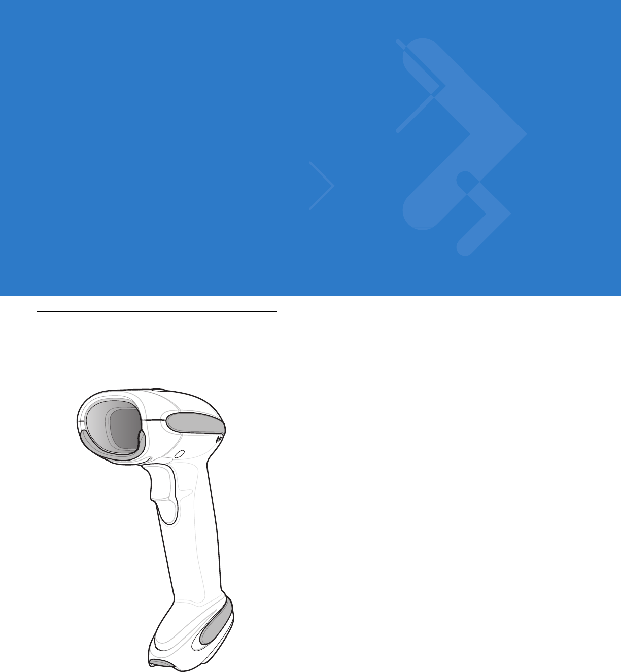
The Symbol DS6878 combines superior 1D and 2D omnidirectional bar code scanning performance and advanced
ergonomics in a light-weight design. The digital scanner ensures comfort and ease of use for extended periods of
time.
Figure 1-1
Symbol DS6878 Digital Scanner

1 - 2 Symbol DS6878 Product Reference Guide
Interfaces
The STB4278 model cradle (p/n: CR0078-SC) supports the following interfaces:
•
USB connection to a host. The cradle auto detects a USB host and defaults to the HID keyboard interface
type. Select other USB interface types by scanning programming bar code menus.This interface supports the
following international keyboards (for Windows® environment): North America, German, French, French
Canadian, Spanish, Italian, Swedish, UK English, Portuguese-Brazilian, and Japanese.
•
Standard RS-232 connection to a host. Scan bar code menus to set up proper communication of the cradle
with the host.
•
Keyboard Wedge connection to a host. The host interprets scanned data as keystrokes. This interface
supports the following international keyboards (for Windows® environment): North America, German,
French, French Canadian, Spanish, Italian, Swedish, UK English, Portuguese-Brazilian, and Japanese.
•
Connection to IBM® 468X/469X hosts. Scan bar code menus to set up communication of the cradle with the
IBM terminal.
•
Wand Emulation connection to a host. The cradle is connected to a portable data terminal, a controller, or
host which collects the data as wand data and decodes it.
•
Scanner Emulation connection to a host. The cradle is connected to a portable data terminal, a controller
which collects the data and interprets it for the host.
•
Synapse capability which allows connection to a wide variety of host systems using a Synapse and Synapse
adapter cable. The cradle auto detects the host.
•
Configuration via 123Scan2.
Unpacking the Digital Scanner and Cradle
Remove the digital scanner and cradle from their respective packing and inspect for damage. If the digital scanner
or cradle was damaged in transit, contact Motorola Enterprise Mobility Support. See page xix for contact
information. KEEP THE PACKING. It is the approved shipping container and should be used if the equipment ever
needs to be returned for servicing.
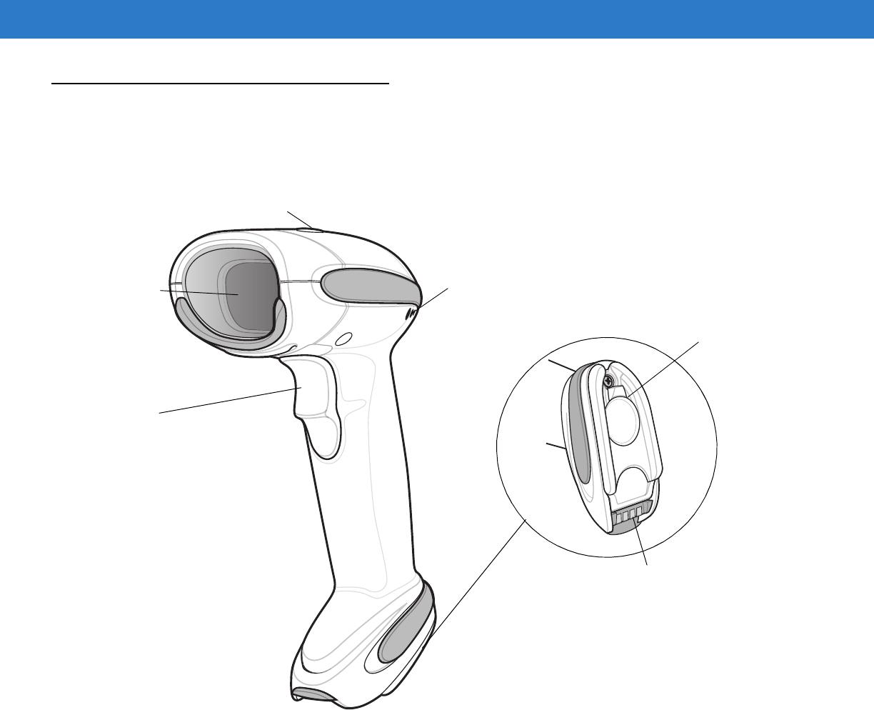
Getting Started 1 - 3
Parts
Scanner
Figure 1-2
Parts of the Digital Scanner
Beeper
LED
Trigger
Scan
Window
Battery Door
Latch
Metal Charging
Contacts
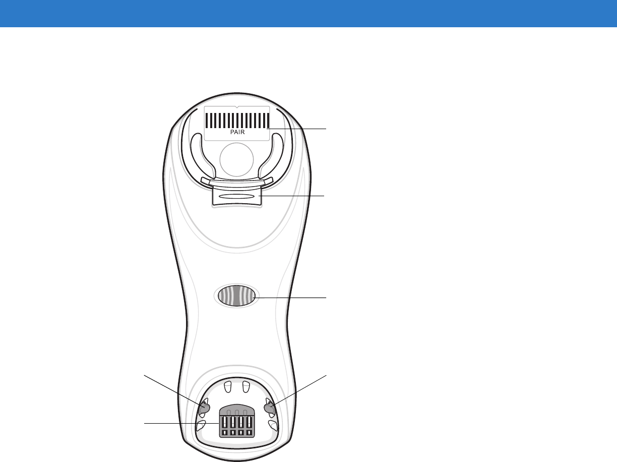
1 - 4 Symbol DS6878 Product Reference Guide
Cradle
Figure 1-3
Cradle Front View
Pairing
Bar Code
Latch Latch
Charging/
Communications
Contacts
Charging LED
Convertible
Mount Hook
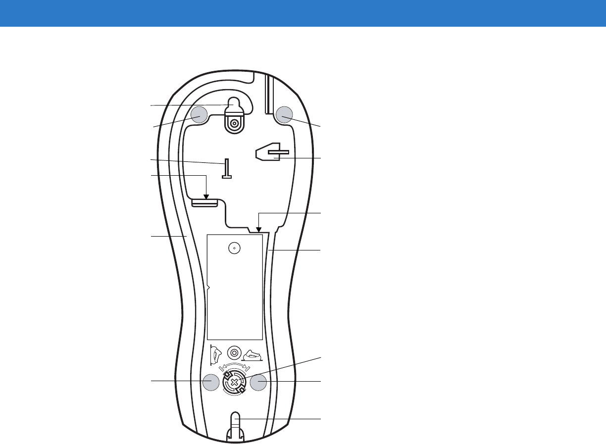
Getting Started 1 - 5
Figure 1-4
Cradle Back View
Rubber Foot Rubber Foot
Mounting Hole
Host Cable Groove
Rubber Foot Rubber Foot
Power Port
Host Port
Power Cable Groove
Desk/Wall Mount
Converter Knob
Mounting Hole
Power Cable Hook Host Cable Hook
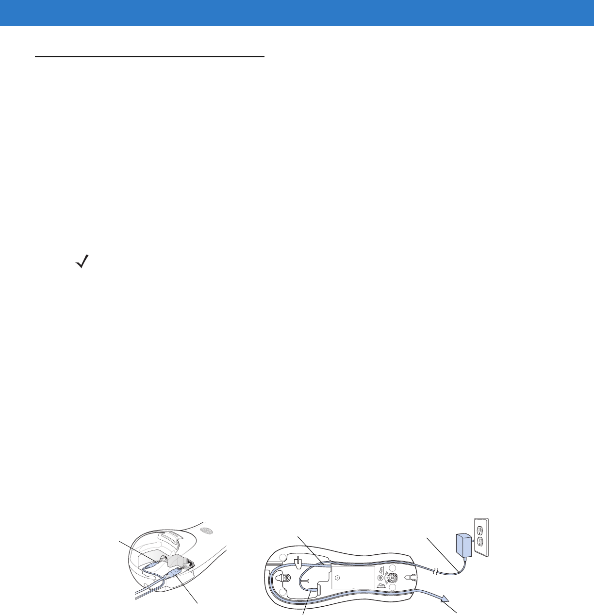
1 - 6 Symbol DS6878 Product Reference Guide
Digital Scanner Cradle
The digital scanner cradle serves as a stand, charger, and host interface for the digital scanner. The cradle sits on
a desktop or mounts on a vertical surface (such as a wall). For more information about mounting options and
procedures, refer to the documentation included with the cradle.
There are two versions of the cradle:
•
Charging cradle with radio: When the cordless digital scanner is paired to the cradle, all communication
between the digital scanner and the host computer is accomplished through the cradle. Each bar code
contains programming instructions or other data unique to the bar code pattern. The digital scanner is paired
to the cradle and transmits bar code data to the cradle via Bluetooth Technology Profile Support. The cradle
then sends that information via an interface cable to the host computer for interpretation.
•
Charge-only cradle: This cradle serves as a stand and battery charger. It does not contain a radio and has
no communication capability.
Connecting the Cradle
Important: Connect the interface cable and power supply (if necessary) in the following order to ensure proper
operation of the digital scanner and cradle:
1. If a power supply is connected to the cradle, disconnect it. See Figure 1-5.
2. If using an interface cable, insert the cable into the cradle’s host port.
3. If using a power supply that connects to the interface cable, insert this power supply into the power connector
on the interface cable, and the other end to an AC supply.
4. Insert the other end of the interface cable into the appropriate port on the host computer (see the specific host
chapter for information on host connections).
5. If using an external power supply (if required by the interface, or to allow fast charging of the digital scanner),
insert the power cable into the power port on the back of the cradle, and connect the power supply to an
approved AC supply (refer to the STB4278/STB4208 Cradle Quick Reference Guide for more information).
Figure 1-5
Connecting the Cables to the Cradle
NOTE For more information about communication between the digital scanner, cradle and host, see Chapter 4,
Radio Communications.
Power Port
Host Port Power Port
Host Port
Connect to appropriate host
Power

Getting Started 1 - 7
6. If applicable, thread the interface cable over the cable support hook and run the host and power cables into
their respective cable grooves.
7. Mount the cradle, as necessary. (For information on mounting the cradle, refer to the documentation included
with the cradle.)
Supplying Power to the Cradle
The cradle receives power from one of two sources:
•
An external power supply.
•
When connected to the host through a host cable that supplies power.
The cradle detects whether the host or the external supply is supplying power. It always draws power from the
external supply when available, regardless of the presence of power from a host.
Using the USB Interface to Supply Power
When the cradle is connected to the host via the USB interface, it can be powered by the USB port instead of an
external power supply. Powering from a USB host limits charging. The digital scanner charges at a slower rate than
when charging from an external power supply.
Lost Connection to Host
If scanned data does not transmit to the cradle’s host, ensure that all cables are firmly inserted and the power
supply is connected to an appropriate AC outlet. If scanned data still does not transmit to the host, reestablish a
connection with the host:
1. Disconnect the power supply from the cradle.
2. Disconnect the host interface cable from the cradle.
3. Wait three seconds.
4. Reconnect the host interface cable to the cradle.
5. Reconnect the power supply to the cradle, if required.
6. Reestablish pairing with the cradle by scanning the pairing bar code.
Mounting the Cradle
For information on mounting the cradle, refer to the documentation included with the cradle.
NOTE Disconnect the power supply before changing host cables, or the cradle may not recognize the new host.
Different cables are required for different hosts. The connectors illustrated in each host chapter are
examples only. The connectors may be different from those illustrated, but the steps to connect the cradle
remain the same.
NOTE The radio link functions normally when the cradle draws power from a USB host.
NOTE The STB4278 does not always require a power supply whereas the STB4208 always requires a power
supply.
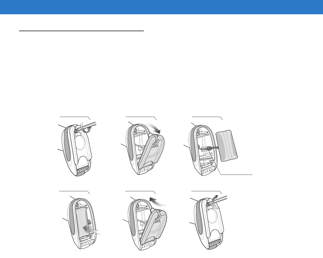
1 - 8 Symbol DS6878 Product Reference Guide
Replacing the Digital Scanner Battery
The battery is installed in the cordless digital scanner by the factory and resides in a chamber in the digital scanner
handle. To replace the battery:
1. Insert a Phillips screwdriver in the screw at the base of the digital scanner, then turn the screw
counterclockwise to release the latch.
2. Remove the latch.
3. If a battery is already installed, turn the digital scanner upright to slide the battery out. Disconnect the battery
connector clip.
Figure 1-6
Inserting the Battery
4. With the contacts on the connector clips facing in the same direction, attach the new battery’s connector clip to
the connector clip in the base of the digital scanner.
5. Slide the new battery into the battery well and ensure the battery leads are visible. The battery should sit
securely in the well.
6. Attach and close the latch.
7. Insert a Phillips screwdriver in the screw at the base of the digital scanner, press down gently, and turn the
screw clockwise to lock the latch in place.
45 6
1 2 3
Battery
Connector Clips
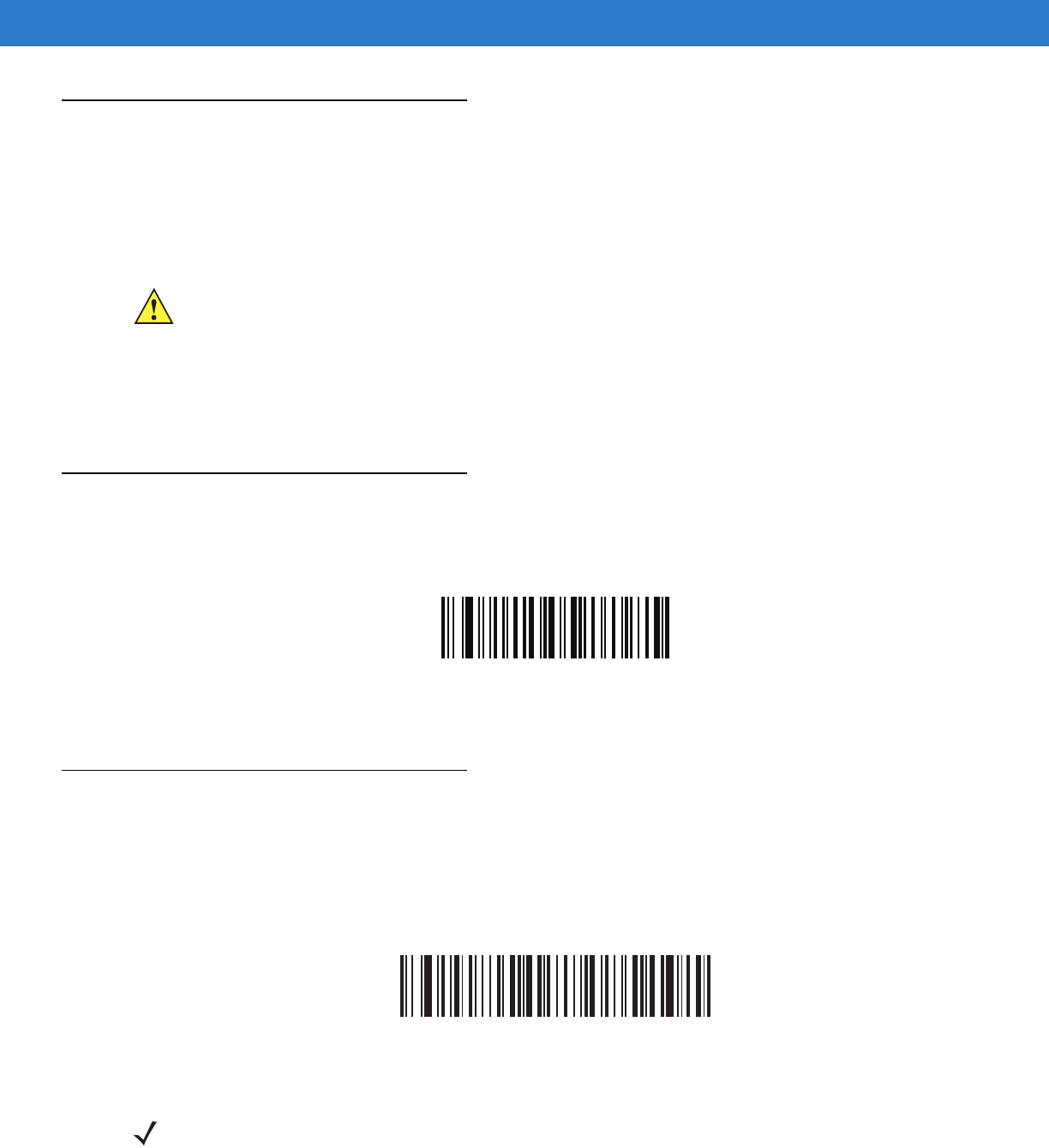
Getting Started 1 - 9
Charging the Digital Scanner Battery
Fully charge the digital scanner battery before using the digital scanner for the first time. To charge the digital
scanner battery, place the digital scanner in the cradle, ensuring that the metal contacts on the bottom of the digital
scanner touch the contacts on the cradle. The battery begins charging when the digital scanner LED indicator
starts flashing green. A complete charge of a fully discharged battery can take up to three hours using external
power and up to five hours using non-external cable power.
Charging LED
When powered up, the cradle LED is always green. The digital scanner LED flashes a green during charging. See
Table 2-2 on page 2-3 for all charging LED indications.
Shutting Off the Digital Scanner Battery
To shut off the NiMH battery for long term storage or shipping:
1. Scan Battery Off bar code below.
Battery Off
2. To turn the battery back on, place the digital scanner in the cradle.
Reconditioning the Digital Scanner Battery
To maintain optimal performance of the digital scanner NiMH battery, perform a battery recondition approximately
once a year.
To begin the battery recondition cycle:
1. Scan Battery Recondition below.
Battery Recondition
2. Place the digital scanner into the cradle.
CAUTION To avoid a battery temperature fault, always charge the battery in the digital scanner within the
recommended temperature of 32° to 104° F (0° to 40° C) nominal, 41° to 95° F (5° to 35° C) ideal.
NOTE If the scanner is removed from the cradle during the battery reconditioning cycle, the scanner exits the
battery reconditioning mode of operation and returns to the normal mode of battery charging (see
Charging the Digital Scanner Battery on page 1-9). To restart the battery reconditioning cycle, re-scan the
Battery Recondition parameter and place the scanner in the cradle.
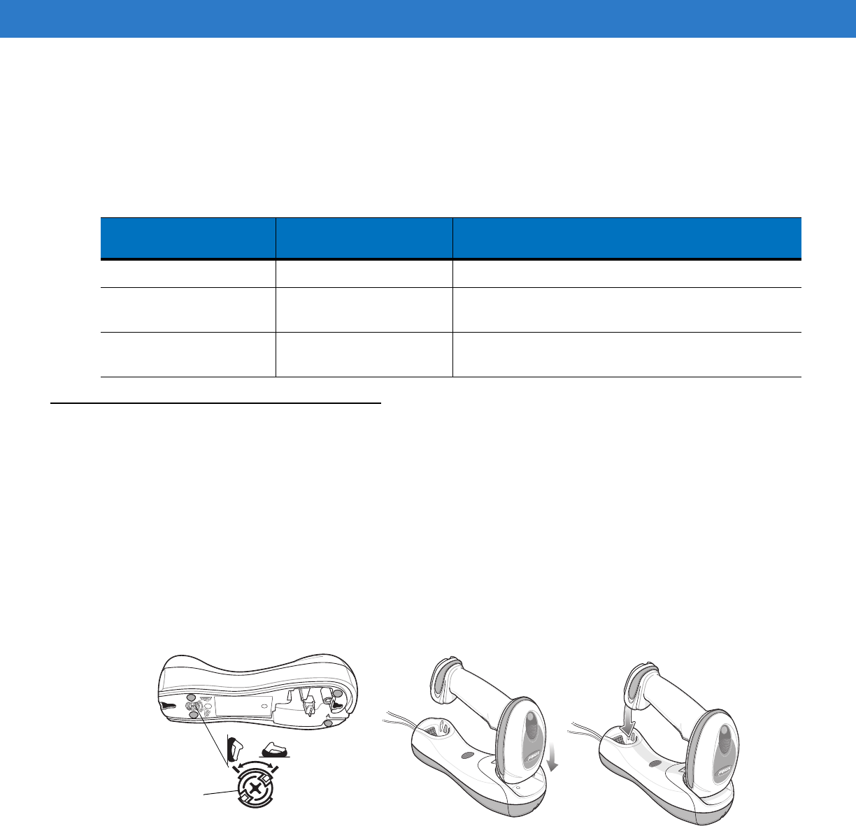
1 - 10 Symbol DS6878 Product Reference Guide
3. The digital scanner must perform two charge cycles to complete the battery reconditioning process
(discharge/charge/discharge/charge). See Table 1-1.
Battery Reconditioning LED Definitions
Inserting the Digital Scanner in the Cradle
Insert the digital scanner in the cradle so that the metal contacts on the bottom of the digital scanner handle touch
the contacts on the cradle. Push the handle lightly to ensure a proper connection, engaging the contacts in the
cradle and digital scanner. Ensure the desk/wall mount converter knob on the back of the cradle is in the correct
position for the horizontal or vertical mounting.
Horizontal Cradle Mount
When mounting the cradle horizontally, where no fastening is necessary:
1. Ensure the rubber feet are attached to the cradle. These feet provide traction and prevent surface damage.
2. Ensure the desk/wall mount converter knob is in the position shown in Figure 1-7.
Figure 1-7
Horizontal Mount - Inserting the Digital Scanner in the Cradle
Vertical Cradle Mount
When mounting the cradle vertically:
1. Ensure the rubber feet are attached to the cradle. These feet provide traction and prevent surface damage.
Table 1-1
Battery Reconditioning LED Definitions
Battery Reconditioning
Mode LED Comments
Discharging Red Flash Time to discharge is approximately 2.5 hours.
Charging Green Flash Time to charge is approximately 2.5 hours with an
external power supply.
Reconditioning Complete Green - Solid (always on) The digital scanner enters a trickle charge until the
digital scanner is removed from the cradle.
Desk/Wall Mount
Converter Knob
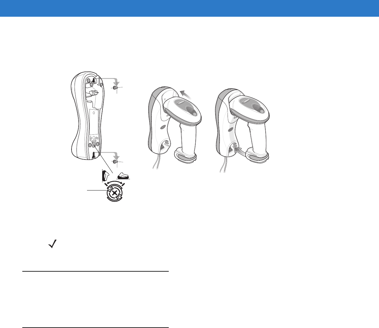
Getting Started 1 - 11
2. Ensure the convertible mount hook on the front of the cradle is inserted with the hook facing up. If not, remove
and reverse the hook so that it is in position to secure the digital scanner in place. (See Figure 1-3 on page 1-4
for the location of the convertible mount hook.)
3. Ensure the desk/wall mount converter knob is in the position shown in Figure 1-8.
Figure 1-8
Vertical Mount - Inserting the Digital Scanner in the Cradle
Radio Communications
The digital scanner can communicate with remote devices via Bluetooth Technology Profile Support, or by pairing
with a cradle. For radio communication parameters, detailed information about operational modes, Bluetooth
Technology Profile Support and pairing, see Chapter 4, Radio Communications.
Configuring the Digital Scanner
Use the bar codes in this manual or the 123Scan2 configuration program to configure the digital scanner. See
Chapter 5, User Preferences & Miscellaneous Digital Scanner Options for information about programming the
digital scanner using bar code menus. Also see each host-specific chapter to set up connection to a specific host
type. See Chapter 12, 123Scan2 to configure the digital scanner using this configuration program.
Desk/Wall
Mount
Converter Knob
NOTE For your convenience, a wall mount bracket can be purchased from Motorola. For the appropriate
measurements and instructions on mounting the cradle, refer to the STB4278/STB4208 Quick Reference
Guide (p/n 72-71010-xx).
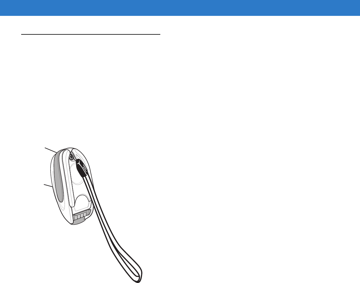
1 - 12 Symbol DS6878 Product Reference Guide
Accessories
The digital scanner and cradle accessories that are available separately include:
•
Power supplies for applications that do not supply power over the host cable. See each host interface
chapter for set up information.
•
Wall-mount bracket for mounting the cradle vertically. Refer to the STB4278/STB4208 Cradle Quick
Reference Guide (p/n 72-71010-xx) for a wall mounting template and installation instructions.
•
Lanyard for wearing the digital scanner on a wrist.
Lanyard
The lanyard attaches to the inside of the digital scanner battery door latch.
Figure 1-9
Attached Lanyard
To attach the lanyard:
1. Open the battery door latch as described in Replacing the Digital Scanner Battery on page 1-8. Do not remove
the battery.

Getting Started 1 - 13
2. Hook the loop of the lanyard around the screw container inside the battery door latch, between the loop guides.
Figure 1-10
Attaching Lanyard
3. Close the battery door latch.
4. Tighten the screw.
Battery Door
Latch
Loop Guides
Screw Container

1 - 14 Symbol DS6878 Product Reference Guide
Chapter 2 Scanning
Introduction
This chapter provides beeper and LED definitions, scanning techniques, general instructions and tips about
scanning, and decode ranges.
Beeper Definitions
The digital scanner issues different beep sequences and patterns to indicate status. Table 2-1 defines beep
sequences that occur during both normal scanning and while programming the digital scanner. (For additional
beeper definitions, see Wireless Beeper Definitions on page 4-3.
Table 2-1
Standard Beeper Definitions
Beeper Sequence Indication
Standard Use
Low/medium/high beeps Power up.
High beep A bar code symbol was decoded (if decode beeper is enabled).
Four long low beeps 1. A transmission error was detected in a scanned symbol. The
data is ignored. This occurs if a unit is not properly configured.
Check option setting.
2. When communicating with a cradle, the cradle acknowledges
receipt of data. If the acknowledgment is not received, this
transmission error beep sequence sounds. Data may still have
been received by the host. Check the host system for receipt of
transmitted data. If data was not received by the host, re-scan the
bar code.
Four short beeps Low battery warning.
Five low long beeps Conversion or format error.

2 - 2 Symbol DS6878 Product Reference Guide
Low beep Digital scanner detects power when inserted into a cradle.
Note: This feature is enabled by default and can be disabled (see
Beep on Insertion on page 5-9
).
Low/high/low/high beeps Out of memory - unable to store a new bar code.
Low/high/low beeps ADF transmit error.
High/high/high/low beeps RS-232 receive error.
Parameter Menu Scanning
Long low/long high beeps Input error, incorrect bar code or
Cancel
scanned, wrong entry,
incorrect bar code programming sequence; remain in program
mode.
High/low beeps Keyboard parameter selected. Enter value using bar code keypad.
High/low/high/low beeps Successful program exit with change in the parameter setting.
Long low/long high/long low/long high beeps Out of host parameter storage space. Scan
Default Parameters on
page 5-4
.
Image Capture
Low beep Snapshot mode started or completed.
High/low beeps Snapshot mode timed out.
Wireless Operation
High/low/high/low beeps Pairing bar code scanned.
Low/high beeps Bluetooth connection established.
High/low beeps Bluetooth disconnection event.
Note: When connected to a remote device using SPP or HID, if a
disconnect beep sequence sounds immediately after a bar code is
scanned, check the host device for receipt of transmitted data. It is
possible that an attempt was made to transmit the last bar code
scanned after the connection was lost.
Long low/long high beeps Page timeout; remote device is out of range/not powered.
Long low/long high/long low/long high beeps Connection attempt was rejected by remote device.
Code 39 Buffering
High/low beeps New Code 39 data was entered into the buffer.
Three long high beeps Code 39 buffer is full.
High/low/high beeps The Code 39 buffer was erased.
Low/high/low beeps The Code 39 buffer was erased or there was an attempt to clear or
transmit an empty buffer.
Low/high beeps A successful transmission of buffered data.
Table 2-1
Standard Beeper Definitions (Continued)
Beeper Sequence Indication
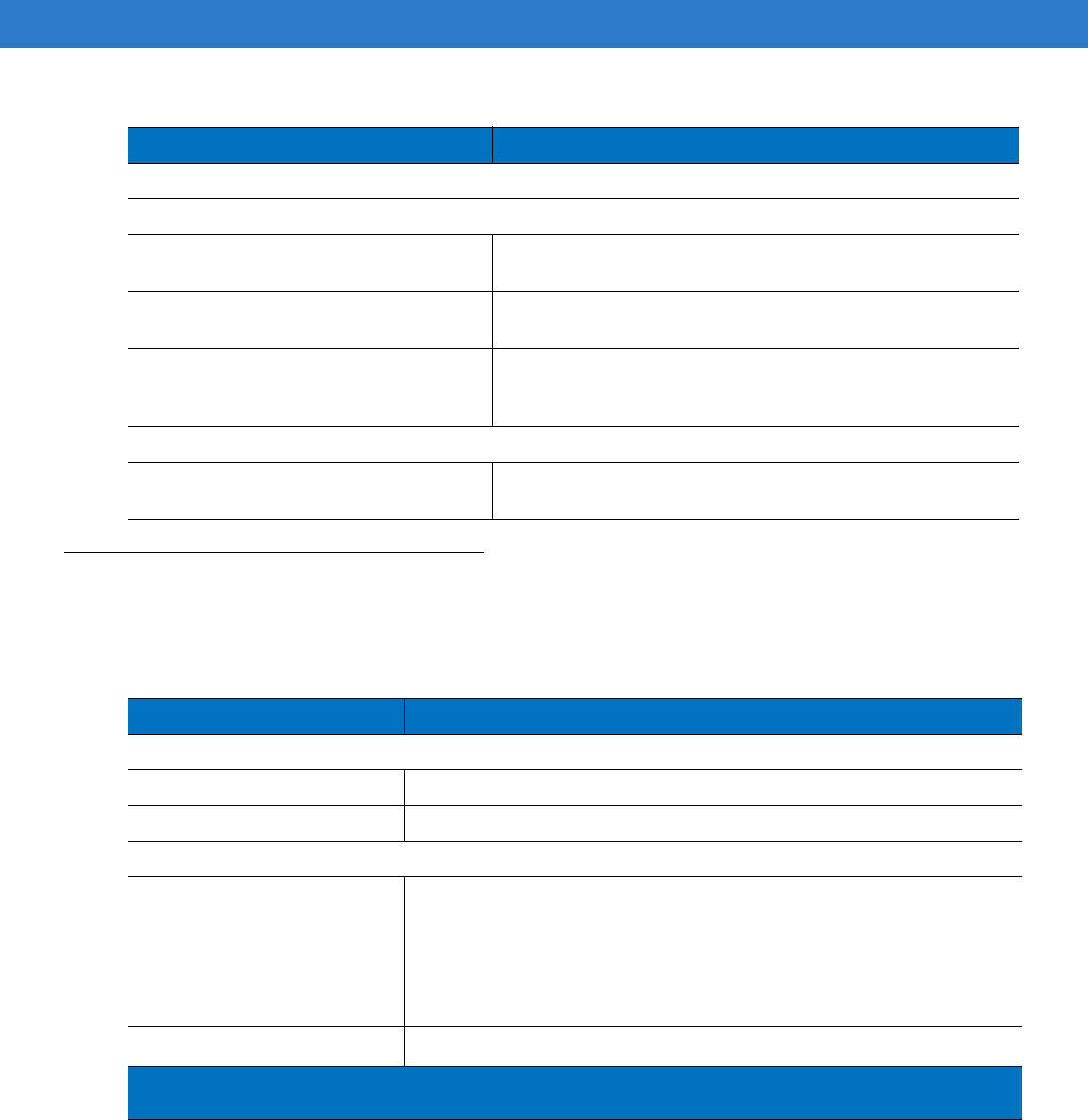
Scanning 2 - 3
LED Definitions
In addition to beeper sequences, the digital scanner communicates with the user using a two-color LED display.
Table 2-2 defines LED colors that display during scanning.
Host Specific
USB only
Four high beeps Digital scanner has not completed initialization. Wait several
seconds and scan again.
Digital scanner gives a power-up beep after
scanning a USB Device Type. Communication with the bus must be established before the digital
scanner can operate at the highest power level.
This power-up beep occurs more than once. The USB bus may put the digital scanner in a state where power to
the digital scanner is cycled on and off more than once. This is
normal and usually happens when the host PC cold boots.
RS-232 only
High beep A <BEL> character is received and Beep on <BEL> is enabled
(Point-to-Point mode only).
Table 2-1
Standard Beeper Definitions (Continued)
Beeper Sequence Indication
Table 2-2
Standard Scanner LED Definitions
LED Indication
Scanning
Green Flash A bar code was successfully decoded.
Red Transmission error or digital scanner malfunction.
Charging
Green - Slow Continuous Flash
1
Non-critical battery temperature fault. Battery is above or below normal
operating temperature.
If this occurs, do not use the digital scanner and move the digital scanner to a
location within normal operating temperature. The digital scanner can remain in
the cradle while the battery warms or cools to normal operating temperature.
Note: For appropriate charging temperatures, see
Table 3-3 on page 3-8
.
Green - Fast Continuous Flash
2
Digital scanner is charging.
1
A slow continuous flash is estimated at 1 flash per second.
2
A fast continuous flash is estimated at 2 flashes per second.

2 - 4 Symbol DS6878 Product Reference Guide
Green - Solid Digital scanner is fully charged.
Red Battery may require pre-charge.
Amber - Continuous Flash Critical battery temperature fault. Battery is above or below normal operating
temperature.
If this occurs, do not use the digital scanner and move the digital scanner to a
location within normal operating temperature. The digital scanner can remain in
the cradle while the battery warms or cools to normal operating temperature.
Note: For appropriate charging temperatures, see
Table 3-3 on page 3-8
.
Table 2-3
Standard Cradle LED Definitions
LED Indication
Green Cradle is powered.
Green Flash Cradle is externally powered with a USB host interface that suspended the
cradle. The cradle is no longer connected to the digital scanner but it will
charge the digital scanner. Scan the pairing bar code to pair the scanner and
cradle (see
Pairing on page 4-19
).
Red Flash Transmission error.
1
A slow continuous flash is estimated at 1 flash per second.
2
A fast continuous flash is estimated at 2 flashes per second.
Table 2-2
Standard Scanner LED Definitions (Continued)
LED Indication
1
A slow continuous flash is estimated at 1 flash per second.
2
A fast continuous flash is estimated at 2 flashes per second.
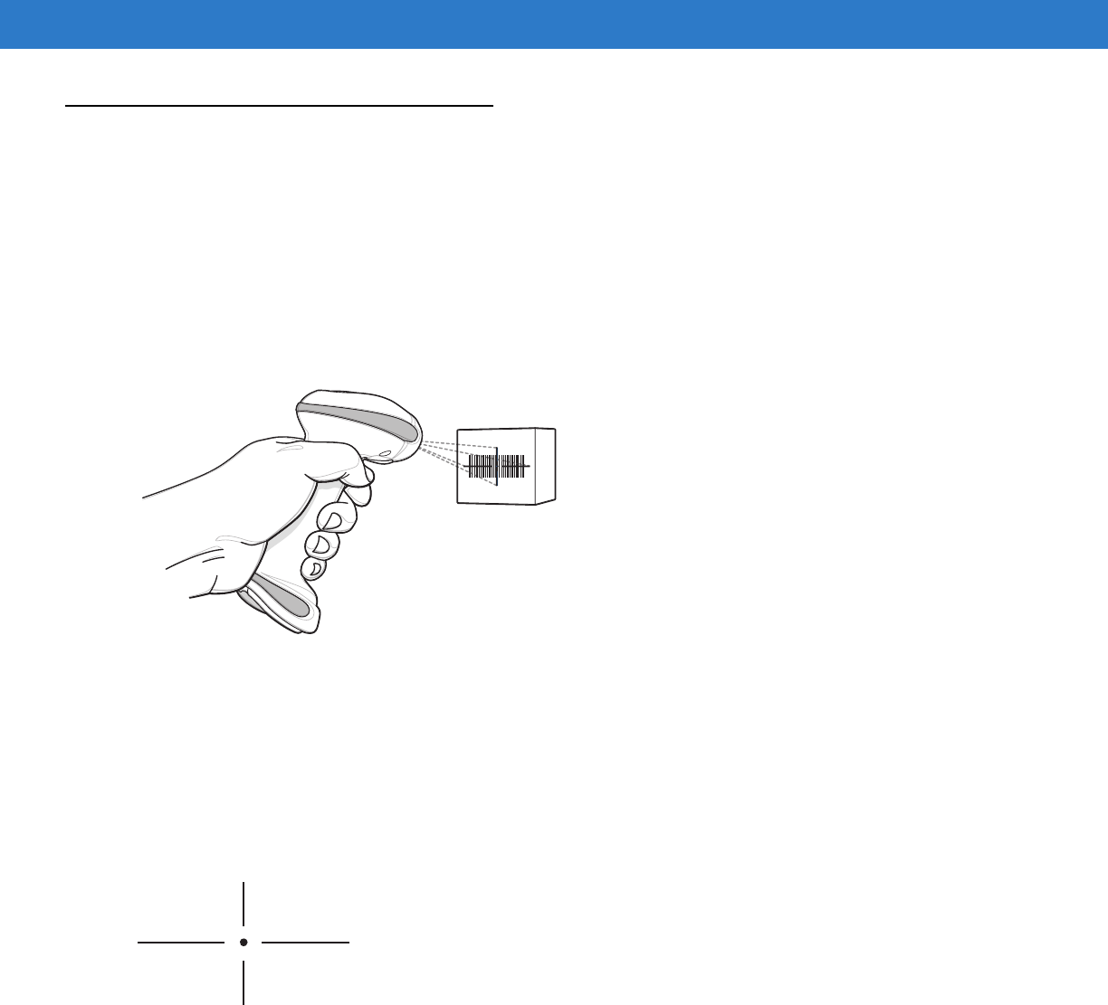
Scanning 2 - 5
Scanning
To program the digital scanner, see the appropriate host chapter, Chapter 4, Radio Communications and Chapter
14, Symbologies. (In addition to the parameters included in the chapters mentioned, user preference and
miscellaneous digital scanner option parameters are also available in this guide.)
To scan:
1. Ensure all connections are secure (see appropriate host chapter).
2. Aim the digital scanner at the bar code.
3. Press the trigger.
Figure 2-1
Scanning
4. Upon successful decode, the digital scanner beeps and the LED turns green. (For more information about
beeper and LED definitions, see Table 2-1 and Table 2-2.)
Aiming
When scanning, the digital scanner projects a red laser aiming pattern which allows positioning the bar code within
its field of view. See Decode Ranges on page 2-7 for the proper distance to achieve between the digital scanner
and a bar code.
Figure 2-2
Imager Aiming Pattern
If necessary, the digital scanner turns on its red LEDs to illuminate the target bar code.
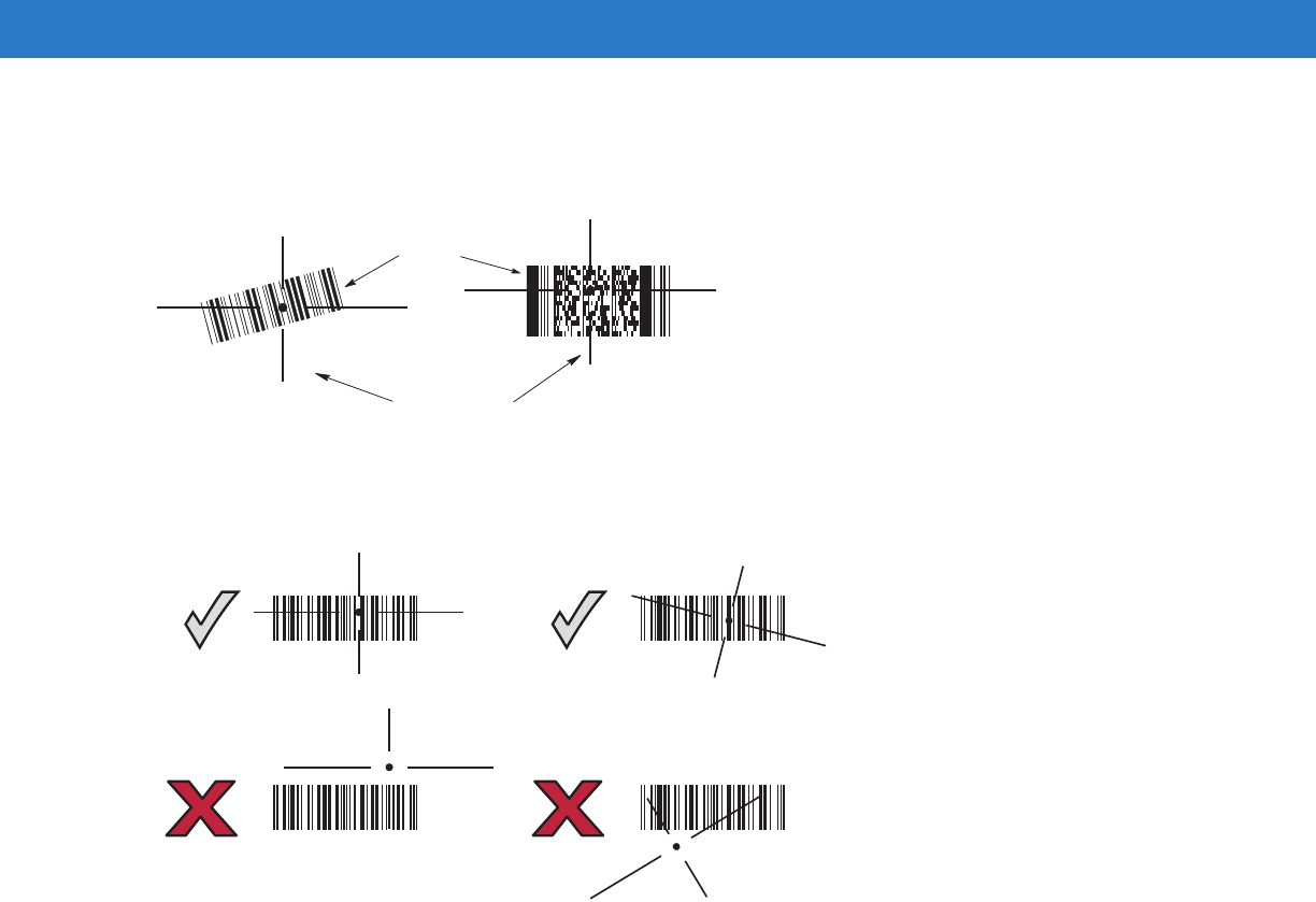
2 - 6 Symbol DS6878 Product Reference Guide
To scan a bar code, center the symbol in any orientation within the aiming pattern. Be sure the entire symbol is
within the rectangular area formed by the cross pattern.
Figure 2-3
Scanning Orientation with Imager Aiming Pattern
The digital scanner can also read a bar code presented within the aiming pattern but not centered. The top
examples in Figure 2-4 show acceptable aiming options, while the bottom examples can not be decoded.
Figure 2-4
Acceptable and Incorrect Aiming
Symbol
Aiming Pattern
1D bar code 2D bar code
012345
012345
012345
012345
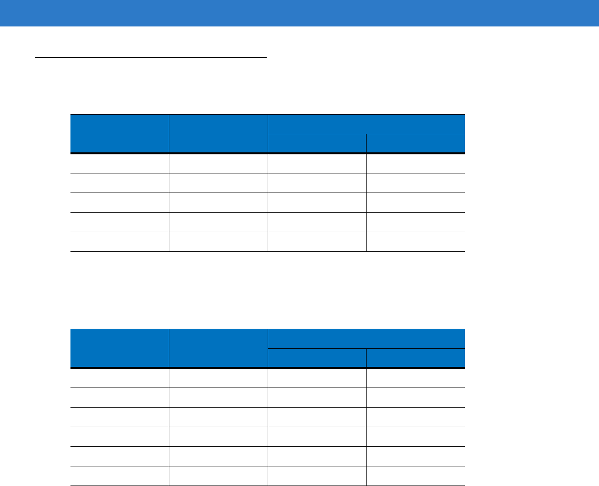
Scanning 2 - 7
Decode Ranges
Figure 2-5
DS6878-SR / DS6878-HC / DS6878-DL Decode Ranges
Figure 2-6
DS6878-HD Decode Ranges
Symbol Density Bar Code Type
Typical Working Ranges
Near Far
5 mil Code 39 0.7 6.6
13 mil 100% UPC 1.2 14.2
5 mil PDF 2.0 4.5
6.6 mil PDF 1.2 6.0
10 mil Data Matrix 1.1 ??? 7.2 ???
Symbol Density Bar Code Type
Typical Working Ranges
Near Far
3 mil Code 39 0.6 3.4
5 mil Code 39 FOV 4.9
13 mil 100% UPC 1.2 6.8
4 mil PDF 0.9 2.8
5 mil Data Matrix 0.9 ??? 3.5 ???
10 mil Data Matrix 0.5 ??? 3.7 ???

2 - 8 Symbol DS6878 Product Reference Guide

Chapter 3 Maintenance, Troubleshooting &
Technical Specifications
Introduction
This chapter provides suggested digital scanner and cradle maintenance, troubleshooting, technical specifications,
and signal descriptions (pinouts).
Maintenance
Digital Scanner
Cleaning the exit window is required. A dirty window may affect scanning accuracy.
•
Do not allow any abrasive material to touch the window.
•
Remove any dirt particles with a damp cloth.
•
Wipe the window using a tissue moistened with ammonia/water.
•
Do not spray water or other cleaning liquids directly into the window.
The DS6878 design allows safe cleansing of the product plastics with a variety of cleaning products and
disinfectants. If required, wipe the digital scanner with the following list of approved cleansers:
•Super Sani-Cloth® Wipes
•Clorox® Bleach
•Windex® Antimicrobial
•Cavi-Wipes
•Isopropyl 70-80%
•Virex® 5 Wipes®
•Ethanol 80%
•Gentle dish soap and water
3 - 2 Symbol DS6878 Product Reference Guide
Cradle
•
Do not pour, spray, or spill any liquid on the cradle. Wipe cradle using approved cleansers.
Battery Information
Rechargeable battery packs are designed and constructed to the highest standards within the industry. However,
there are limitations to how long a battery can operate or be stored before needing replacement. Many factors
affect the life of a battery pack such as heat, cold, customer usage profiles, age and severe drops.
When batteries are stored over a year, battery cell manufacturers advise that some irreversible deterioration in
overall battery quality may occur. To minimize this loss, they recommend storing batteries half charged in a dry,
cool place between 41° F and 77° F (5° C and 25° C), the cooler the better, and removed from the equipment to
prevent the loss of capacity. Batteries should be charged to half capacity at least once a year. If an electrolyte
leakage is observed, avoid any contact with the affected area and properly dispose of the battery.
Replace the battery when a significant loss of run time is detected. Batteries must be charged within the 32° F to
104° F (0° C to 40°C) temperature range.
The standard warranty period for all Symbol batteries is 30 days, regardless if the battery was purchased
separately or included as part of the mobile computer. For more information on Symbol batteries, please visit:
http://support.symbol.com/support/product/manuals.do
Troubleshooting
CAUTION Avoid using cleansers directly on the digital scanner battery door, contacts and cradle contacts. Use a
cotton swab moistened with alcohol to gently clean contacts.
Table 3-1
Troubleshooting
Problem Possible Causes Possible Solutions
Battery
Digital Scanner battery requires
frequent charging. Battery may need reconditioning. Restore the battery by performing a
battery reconditioning cycle. See
Reconditioning the Digital Scanner
Battery on page 1-9
for more
information.
Digital Scanner displays solid red
LED longer than 3 seconds when
placed in cradle.
Battery may require pre-charge
due to excessive discharge. Wait for the red LED to turn green
indicating that the scanner has begun
normal charging. Recommend allowing
battery to fully recharge.

Maintenance, Troubleshooting & Technical Specifications 3 - 3
Beeper Indications
Digital Scanner emits low/high/low
beeps. ADF transmit error. See Chapter 15, Advanced Data
Formatting for information about ADF
programming.
Invalid ADF rule is detected. See Chapter 15, Advanced Data
Formatting for information about ADF
programming.
The Code 39 buffer was erased or
there was an attempt to clear or
transmit an empty buffer.
Normal when scanning the Code 39
Buffering
Clear Buffer
bar code or
upon attempt to transmit an empty
Code 39 buffer.
Digital Scanner emits a
low/high/low/high beep sequence
while it is being programmed.
Out of ADF parameter storage
space. Erase all rules and re-program with
shorter rules.
Digital Scanner emits long low/long
high beeps. Input error, incorrect bar code or
Cancel
bar code was scanned. Scan the correct numeric bar codes
within range for the parameter
programmed.
Page timeout; remote device is
out of range/not powered. Move the digital scanner back into
range of the remote device; try to
re-connect; check remote device
configuration.
Digital Scanner emits long low/long
high/long low/long high beeps. Out of host parameter storage
space. Scan
Default Parameters on page
5-4
.
Out of memory for ADF rules. Reduce the number of ADF rules or the
number of steps in the ADF rules.
Connection attempt was rejected
by remote device. Free up remote device resources.
Digital Scanner emits
high/high/high/low beeps. RS-232 receive error. Normal during host reset. Otherwise,
set the digital scanner's RS-232 parity
to match the host setting.
Table 3-1
Troubleshooting (Continued)
Problem Possible Causes Possible Solutions

3 - 4 Symbol DS6878 Product Reference Guide
Digital Scanner emits high/low
beeps. The digital scanner is buffering
Code 39 data.
Or
Keyboard parameter selected.
Normal.
Or
Enter value using bar code keypad.
Bluetooth disconnection event. Move the digital scanner back into
range of the remote device.
In Master (SPP) mode, re-pair the
digital scanner and cradle by scanning
the
PAIR
bar code on the cradle; check
cradle power.
In Slave (SPP/HID) mode, reestablish
connection between the digital scanner
and remote device from the remote
device side.
Digital Scanner emits three long high
beeps. Code 39 buffer is full. Scan the Code 39 bar code without a
leading space or scan
Do Not Buffer
Code 39
on
Code 39 Buffering - Scan
& Store on page 14-32
to transmit
stored Code 29 data.
Digital Scanner emits four high
beeps on trigger release. Low battery. Place digital scanner in cradle to
charge the battery.
Digital Scanner emits four long low
beeps. A transmission error was
detected in a scanned symbol.
The data is ignored.
This occurs if a unit is not properly
configured. Check option setting.
The digital scanner is either:
- Out of range
- Not paired to the cradle
- Not connected to a remote
Bluetooth device.
Move the digital scanner back into
range of the remote device.
Or
Scan the
PAIR
bar code on the cradle.
Acknowledgment that transmitted
data was not received by the
cradle.
Data may have been received by the
host. Check the host system for receipt
of transmitted data. If data was not
received by the host, re-scan the bar
code.
Digital Scanner emits five low long
beeps. Conversion or format error. Check ADF rules for the host.
Decoding Bar Codes
Digital Scanner emits the laser, but
does not decode the bar code. Digital Scanner is not
programmed for the correct bar
code type.
Program the digital scanner to read
that type of bar code. See
Chapter 14,
Symbologies
.
Bar code symbol is unreadable. Scan test symbols of the same bar
code type to determine if the bar code
is defaced.
Table 3-1
Troubleshooting (Continued)
Problem Possible Causes Possible Solutions

Maintenance, Troubleshooting & Technical Specifications 3 - 5
Distance between digital scanner
and bar code is incorrect. Move the digital scanner closer to or
further from the bar code. See
Decode
Ranges on page 2-7
.
The scan line is not crossing
every bar and space of the
symbol.
Move the symbol until the scan line is
within the acceptable aiming pattern.
See
Figure 2-1 on page 2-5
.
Digital Scanner decodes bar code,
but does not transmit the data to the
host.
Digital Scanner is not
programmed for the correct host
type.
Scan the appropriate host type
programming bar code. See the
chapter corresponding to the host type.
Interface cable is loose. Ensure all cable connections are
secure.
Cradle is not programmed for the
correct host interface. Check digital scanner host parameters
or edit options.
Digital Scanner not paired to
host-connected interface. Pair the digital scanner to the cradle by
scanning the
PAIR
bar code on the
cradle.
Cradle has lost connection to
host. In this exact order: disconnect power
supply; disconnect host cable; wait
three seconds; reconnect host cable;
reconnect power supply; reestablish
pairing.
Digital Scanner emits five long low
beep after a bar code is decoded. Conversion or format error was
detected.
The digital scanner’s conversion
parameters are not properly
configured.
Ensure the digital scanner’s conversion
parameters are properly configured.
Conversion or format error was
detected.
An ADF rule was set up with
characters that can't be sent for
the host selected.
Change the ADF rule, or change to a
host that can support the ADF rule.
Conversion or format error was
detected.
A bar code was scanned with
characters that can't be sent for
that host.
Change the bar code, or change to a
host that can support the bar code.
Table 3-1
Troubleshooting (Continued)
Problem Possible Causes Possible Solutions

3 - 6 Symbol DS6878 Product Reference Guide
Host Displays
Host displays scanned data
incorrectly. Digital Scanner is not
programmed to work with the
host.
Ensure the proper host is selected.
Scan the appropriate host type
programming bar code.
For RS-232, ensure the digital
scanner’s communication parameters
match the host’s settings.
For a USB HID keyboard or Keyboard
Wedge configuration, ensure the
system is programmed for the correct
keyboard type and language, and turn
off the CAPS LOCK key.
Ensure editing options (e.g., ADF,
UPC-E to UPC-A Conversion) are
properly programmed.
Check the digital scanner’s host type
parameters or editing options.
Trigger
Nothing happens when the trigger is
pulled. No power to the digital scanner. Check the system power. If the
configuration requires a power supply,
re-connect the power supply.
Check the battery. Ensure that end cap
to battery chamber is secured.
Interface/power cables are loose. Check for loose cable connections and
re-connect cables.
Digital Scanner is disabled. For Synapse or IBM-468x mode,
enable the digital scanner via the host
interface.
The laser aiming or illumination does
not appear when the trigger is
pulled.
No power to the digital scanner. Check battery and charging contacts;
ensure that end cap to battery chamber
is secured; ensure all power and cable
connections to cradle are secure.
Interface/power cables are loose. Check battery and charging contacts;
ensure power and cable connections to
cradle are secure.
Table 3-1
Troubleshooting (Continued)
Problem Possible Causes Possible Solutions
NOTE If after performing these checks the symbol still does not scan, contact the distributor or contact Motorola
Enterprise Mobility Support. See page xix for contact information.

Maintenance, Troubleshooting & Technical Specifications 3 - 7
Technical Specifications
Table 3-2
Technical Specifications - Symbol DS6878 Digital Scanner
Item Description
Physical Characteristics
Dimensions 7.3 in. H x 3.85 in. L x 2.7 in. W
(18.5 cm H x 9.7 cm L x 6.9 cm W)
Weight (with battery) Approximately 8.4 oz. (238 g)
Color Cash Register White or Twilight Black
HC Configuration: Healthcare White
Performance Characteristics
Light Source: Aiming Pattern: 650 nm laser diode
Illumination: 630 nm LED
Frame Rate Decode Mode: 60 fps
Document Capture Mode: 10 fps
Radio Range Minimum 33 ft (10m) / Typical warehouse environment 50 ft. (15m)
Battery Specifications 720maH NiMH - (3) AAA
number of scans per full charge: typically 8,500 @ 1 scan/second
Charge Time:
Fully discharged battery: < 3 hours via external power / approximately 5.5
hours via host power through cable
Roll Tolerance ± 360°
Pitch Tolerance ± 60°
Yaw Tolerance ± 60°
Nominal Working Distance (See
Decode Ranges on page 2-7
)
Decode Capability UPC/EAN and with supplementals, Code 39, Code 39 Full ASCII, Tri-optic
Code 39, GS1 DataBar Variants, GS1-128, Code 128, Code 128 Full ASCII,
Code 93, Codabar (NW1), Interleaved 2 of 5, Discrete 2 of 5 MSI, Codell,
IATA, Bookland EAN, Code 32
Interfaces Supported See
Table 3-3
.
User Environment
Operating Temperature 32° to 122° F (0° to 50° C)
Storage Temperature -40° to 158° F (-40° to 70° C)
Charging Temperature 32° to 104° F (0° to 40° C) nominal, 41° to 95° F (5° to 35° C) ideal
Humidity 5% to 95%, non-condensing
Drop Specifications Withstands multiple 6 ft./1.8 m drops to concrete at room temperature.
Withstands multiple 5 ft./1.5m drops to concrete at 0° to 50° C.
3 - 8 Symbol DS6878 Product Reference Guide
# of Cradle Insertions 250,000+ insertions
Ambient Light Immunity Incandescent - 150 ft. candles (1,600 Lux)
Sunlight - 8,000 ft. candles (86,000 Lux)
Flourescent - 150 ft. candles (1,600 Lux)
Mercury Vapor - 150 ft. candles (1,600 Lux)
Sodium Vapor - 150 ft. candles (1,600 Lux)
Immune to normal or artificial light
Regulatory
Electrical Safety UL 60950-1, C22.2 No. 60950-1, EN 60950-1, IEC 60950-1
Laser Safety EN 60825-1, IEC 60825-1, 21CFR1040.10
EMI/RFI EN 301 489-1, EN 301 489-17, IEC 60601-1-2, EN 55022, FCC Part 15
Class B, ICES 003 Class B, EN 55024, EN 61000-3-2, EN 61000-3-3
European Union EMC Directive, Australian SMA
Environmental RoHS Directive 2002/95/EEC
Radio EN 300 328
RF Exposure EN 50360, EN 50361, FCC Part 2, OET Bulletin 65, RSS102
Accessories
Lanyard Lanyard attaches to the battery door.
Table 3-3
Technical Specifications - STB4278/STB4208 Cradle
Item Description
Physical Characteristics
Dimensions: 2.0 in. H x 8.35 in. L x 3.4 in. W
(5 cm H x 21.1 cm L x 8.6 cm W)
Weight Approximately 6.4 oz. (183 gm)
Voltage & Current Charging Cradle:
Voltage Current
5 +/-10% VDC 700mA (External power)
5 +/-10% VDC 475 mA (Host power through cable)
12 +/-10% VDC 300 mA (External power)
12 +/-10% VDC 220 mA (Host power through cable)
Non-charging Cradle: 5V @ 70ma or 12 V @ 50 mA
Color Cash Register White or Twilight Black
HC Configuration: Healthcare White
Power Requirements 4.75 - 14.0 VDC
Table 3-2
Technical Specifications - Symbol DS6878 Digital Scanner (Continued)
Item Description

Maintenance, Troubleshooting & Technical Specifications 3 - 9
Performance Characteristics
Interfaces Supported
(CR0078-SC only)
Features on-board Multiple Interface with: RS-232C (Standard, Nixdorf, ICL, & Fujitsu);
IBM 468x/469x; Keyboard Wedge; USB (Standard, IBM SurePOS, Macintosh);
Laser/Wand Emulation; 123Scan
2
; Remote Digital Scanner Management.
In addition, Synapse Adaptive Connectivity allows for connectivity to all of the above plus
many non-standard interfaces.
User Environment
Operating Temperature 32° to 122° F (0° to 50° C)
Storage Temperature -40° to 158° F (-40° to 70° C)
Charging Temperature 32° to 104° F (0° to 40° C) nominal, 41° to 95° F (5° to 35° C) ideal
Humidity 5% to 95% (non-condensing)
Regulatory
Electrical Safety UL 60950-1, C22.2 No. 60950-1, EN 60950-1, IEC 60950-1
EMI/RFI EN 301 489-1, EN 301 489-17, IEC 60601-1-2, EN 55022, FCC Part 15 Class B, ICES
003 Class B, EN 55024, EN 61000-3-2, EN 61000-3-3
European Union EMC Directive, Australian SMA
Radio EN 300 328
Environmental RoHS Directive 2002/95/EEC
RF Exposure EN 50360, EN 50361, FCC Part 2, OET Bulletin 65, RSS102
Accessories
Mounting Options Desktop, mount on a wall, computer work station or medical cart.
Power Supplies Power supplies are available for applications that do not supply power over host cable.
Table 3-3
Technical Specifications - STB4278/STB4208 Cradle (Continued)
Item Description
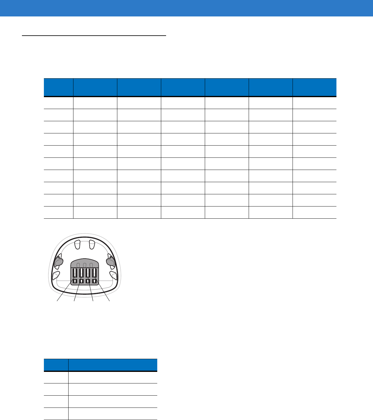
3 - 10 Symbol DS6878 Product Reference Guide
Cradle Signal Descriptions
The signal descriptions in Table 3-4 apply to the connector on the digital scanner and are for reference only.
Figure 3-1 illustrates the positions of the cradle pins.
Figure 3-1
Cradle Pin Assignments
The signal descriptions in Table 3-5 apply to the connector from the digital scanner to the digital scanner cradle and
are for reference only.
Table 3-4
Cradle Signal Pin-outs
Pin IBM Synapse RS-232 Keyboard
Wedge Wand USB
1 Reserved SynClock Reserved Reserved Reserved Jump to Pin 6
2 Power Power Power Power Power Power
3 Ground Ground Ground Ground Ground Ground
4 IBM_A(+) Reserved TxD KeyClock DBP Reserved
5 Reserved Reserved RxD TermData CTS D +
6 IBM_B(-) SynData RTS KeyData RTS Jump to Pin 1
7 Reserved Reserved CTS TermClock Reserved D -
8 Reserved Reserved Reserved Reserved Reserved Reserved
9 N/A N/A N/A N/A N/A N/A
10 N/A N/A N/A N/A N/A N/A
Table 3-5
Cradle Pin-outs
Pin Description
1 CRADLE_TXD
2VCC
3GND
4 CRADLE_RXD
Pin 1
Pin 4 Pin 3 Pin 2

Chapter 4 Radio Communications
Introduction
This chapter provides information about the modes of operation and features available for wireless communication
between digital scanners, cradles and hosts. The chapter also includes the parameters necessary to configure the
digital scanner.
The digital scanner ships with the settings shown in the Radio Communication Default Table on page 4-2 (also see
Appendix A, Standard Default Parameters for all host device and miscellaneous digital scanner defaults). If the
default values suit requirements, programming is not necessary.
To set feature values, scan a single bar code or a short bar code sequence. The settings are stored in non-volatile
memory and are preserved even when the digital scanner is powered down.
If not using a Synapse or USB cable with the cradle, select a host type (see each host chapter for specific host
information) after the power-up beeps sound. This is only necessary upon the first power-up when connected to a
new host.
To return all features to default values, scan a default bar code in Default Parameters on page 5-4. Throughout the
programming bar code menus, default values are indicated with asterisks (*).
Scanning Sequence Examples
In most cases, scan one bar code to set a specific parameter value.
Errors While Scanning
Unless otherwise specified, to correct an error during a scanning sequence, just re-scan the correct parameter.
*Disable Pair on Contacts Feature/Option
* Indicates Default

4 - 2 Symbol DS6878 Product Reference Guide
Radio Communications Parameter Defaults
Table 4-1 lists the defaults for radio communication parameters. If you wish to change any option, scan the
appropriate bar code(s) provided in the Radio Communications Parameters section beginning on page 4-4.
NOTE See Appendix A, Standard Default Parameters for all user preferences, hosts, symbologies, and
miscellaneous default parameters.
Table 4-1
Radio Communication Default Table
Parameter Default Page
Number
Bluetooth Host (Host Type) Cradle Host
4-4
Discoverable Mode General
4-7
Country Keyboard Types (Country Code) North American
4-8
HID Keyboard Keystroke Delay No Delay (0 msec)
4-10
CAPS Lock Override Disable
4-10
Ignore Unknown Characters Enable
4-11
Emulate Keypad Disable
4-11
Keyboard FN1 Substitution Disable
4-12
Function Key Mapping Disable
4-12
Simulated Caps Lock Disable
4-13
Convert Case No Case Conversion
4-13
Beep on Reconnect Attempt Disable
4-14
Reconnect Attempt Interval 30 sec
4-15
Auto-reconnect in Bluetooth Keyboard
Emulation (HID Slave) Mode On Bar Code Data
4-17
Modes of Operation
(Point-to-Point/Multipoint-to-Point
Point-to-Point
4-18
Parameter Broadcast (Cradle Host Only) Enable
4-19
Pairing Modes Unlocked
4-20
Pairing on Contacts Disable
4-21
Connection Maintenance Interval 15 min
4-23
Authentication Disable
4-25
Variable Pin Code Static
4-26
Encryption Disable
4-27

Radio Communications 4 - 3
Wireless Beeper Definitions
When the digital scanner scans the pairing bar code it issues various beep sequences indicating successful or
unsuccessful operations. Table 4-2 defines beep sequences that occur during pairing operations. (For additional
beeper definitions, see Beeper Definitions on page 2-1.).
Table 4-2
Wireless Beeper Definitions
Beeper Sequence Indication
Four long low beeps 1. A transmission error was detected in a scanned symbol. The data is ignored.
This occurs if a unit is not properly configured. Check option setting.
2. When communicating with a cradle, the cradle acknowledges receipt of data. If
the acknowledgment is not received, this transmission error beep sequence
sounds. Data may still have been received by the host. Check the host system for
receipt of transmitted data. If data was not received by the host, re-scan the bar
code.
Five high beeps Emitted every 5 seconds while a reconnection attempt is in progress. (See
Auto-reconnect Feature on page 4-14
.)
High/low/high/low beeps Pairing bar code scanned.
Low/high beeps Bluetooth connection established.
High/low beeps Bluetooth disconnection event.
Note: When connected to a remote device using SPP or HID, if a disconnect beep
sequence sounds immediately after a bar code is scanned, check the host device
for receipt of transmitted data. It is possible that an attempt was made to transmit
the last bar code scanned after the connection was lost.
Long low/long high beeps Page timeout; remote device is out of range/not powered. (See
Auto-reconnect
Feature on page 4-14
.)
Long low/long high/long low/
long high beeps Connection attempt was rejected by remote device.
Note: In the case of
Pairing Methods on page 4-21
, the cradle may already be
connected to another digital scanner in single Point-to-Point locked mode, or the
piconet may be full in Multipoint-to-Point mode. If Pair On Contacts is enabled and
the digital scanner that is inserted is already connected to the cradle, no beeping
occurs.

4 - 4 Symbol DS6878 Product Reference Guide
Radio Communications Host Types
To set up the digital scanner for communication with a cradle, or to use standard Bluetooth profiles, scan the
appropriate host type bar code below.
•
Cradle Host (default) - Select this host type for digital scanner(s) to cradle operation. The digital scanner
must then be paired to the cradle and the cradle communicates directly to the host via the host interface
cable connection.
•
Serial Port Profile (Master) - Select this host type for Bluetooth Technology Profile Support (see page 4-6).
The digital scanner connects to the PC/host via Bluetooth and performs like there’s a serial connection. The
digital scanner initiates the connection to the remote device and is the Master. Scan Serial Port Profile
(Master), then scan the PAIR bar code for the remote device. See Pairing Bar Code Format on page 4-22 for
information about creating a pairing bar code for a remote device.
•
Serial Port Profile (Slave) - Select this host type for Bluetooth Technology Profile Support (see page 4-6). The
digital scanner connects to the PC/host via Bluetooth and performs like there’s a serial connection. The
digital scanner accepts incoming connection requested from a remote device and is the Slave. Scan Serial
Port Profile (Slave) and wait for the incoming connection.
•
Bluetooth Keyboard Emulation (HID Slave) - Select this host type for Bluetooth Technology Profile Support.
(See page 4-6 for Bluetooth Technology Profile Support and Master/Slave definitions.) The digital scanner
connects to the PC/host via Bluetooth and performs like a keyboard. The digital scanner accepts incoming
connection requested from a remote device and is the slave. Scan Bluetooth Keyboard Emulation (HID
Slave) and wait for the incoming connection.
NOTE 1.The digital scanner supports keyboard emulation over the Bluetooth HID profile. For detailed
information, and HID host parameters, see HID Host Parameters on page 4-8.
2. When the digital scanner is paired to the cradle in SPP Master or Cradle Host mode, the digital scanner
automatically tries to reconnect to a remote device when a disconnection occurs that is due to the radio
losing communication. For more information see Auto-reconnect Feature on page 4-14.
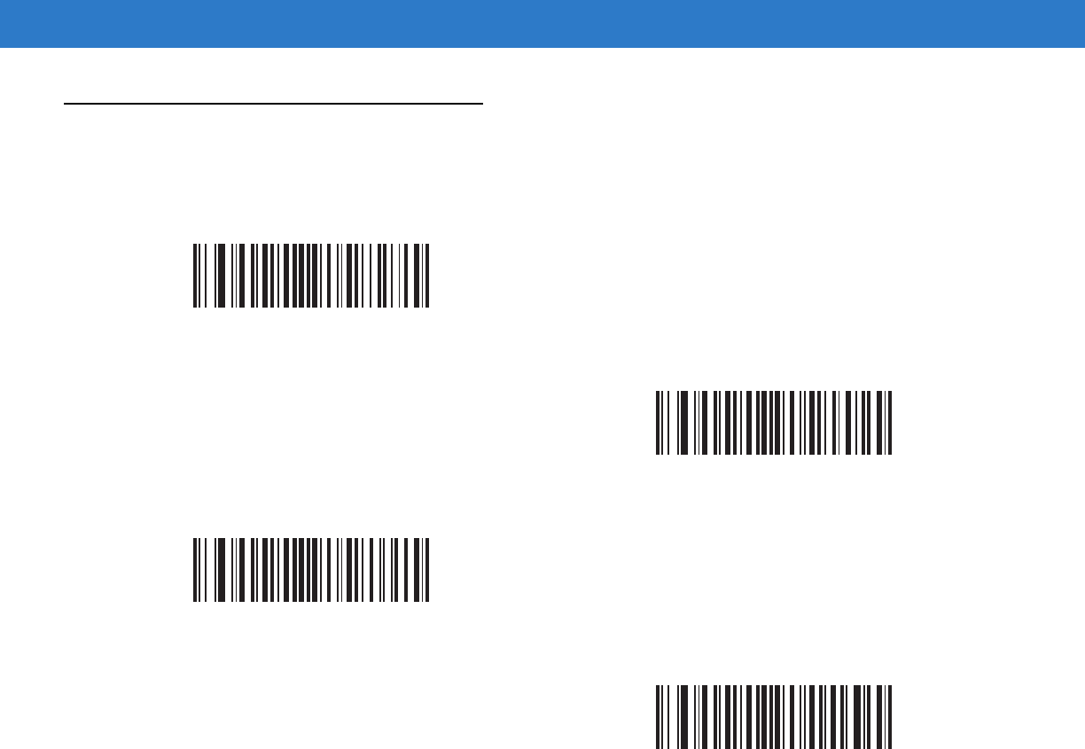
Radio Communications 4 - 5
Radio Communications Host Types (continued)
*Cradle Host
Serial Port Profile (Master)
Serial Port Profile (Slave)
Bluetooth Keyboard Emulation (HID Slave)

4 - 6 Symbol DS6878 Product Reference Guide
Bluetooth Technology Profile Support
With Bluetooth Technology Profile Support, the cradle is not required for wireless communication. The digital
scanner communicates directly to the host using Bluetooth technology. The digital scanner supports the standard
Bluetooth Serial Port Profile (SPP) and HID Profiles which enable the digital scanner to communicate with other
Bluetooth devices that support these profiles.
•
SPP - the digital scanner connects to the PC/host via Bluetooth and performs like there’s a serial connection.
•
HID - the digital scanner connects to the PC/host via Bluetooth and performs like a keyboard.
Master/Slave Set Up
The digital scanner can be set up as a Master or Slave.
When the digital scanner is set up as a Slave, it is discoverable and connectable to other devices. When the digital
scanner is set up as a Master, the Bluetooth address of the remote device to which a connection is requested is
required. A pairing bar code with the remote device address must be created and scanned to attempt a connection
to the remote device. See the Pairing Bar Code Format on page 4-22 for information about creating a pairing bar
code.
Master
When the digital scanner is set up as a Master (SPP), it initiates the radio connection to a slave device. Initiating
the connection is done by scanning a pairing bar code for the remote device (see Pairing Bar Code Format on
page 4-22).
Slave
When the digital scanner is set up as a Slave device (SPP), the digital scanner accepts an incoming connection
request from a remote device.
NOTE The number of digital scanners is dependent on the host’s capability.
Radio Communications 4 - 7
Bluetooth Friendly Name
You can set a meaningful name for the digital scanner that appears in the application during device discovery. The
default name is the digital scanner name followed by its serial number, e.g., DS6878 123456789ABCDEF. Scanning
Set Defaults reverts the digital scanner to this name; use custom defaults to maintain the user-programmed name
through a Set Defaults operation.
To set a new Bluetooth Friendly Name, scan the following bar code, then scan up to 23 characters from Appendix
E, Alphanumeric Bar Codes. If the name contains less than 23 characters, scan End of Message on page E-7 after
entering the name.
Discoverable Mode
Select a discoverable mode based on the device initiating discovery:
•
Select General Discoverable Mode when initiating connection from a PC.
•
Select Limited Discoverable Mode when initiating connection from a mobile device (e.g., Motorola Q), and
the device does not appear in General Discoverable Mode. Note that it can take longer to discover the device
in this mode.
The device remains in Limited Discoverable Mode for 30 seconds, and green LEDs flash while in this mode.
It is then non-discoverable. To re-active Limited Discoverable Mode, press the trigger.
NOTE If your application allows you to set a device name, this takes precedence over the Bluetooth Friendly
Name.
Bluetooth Friendly Name
*General Discoverable Mode
Limited Discoverable Mode
4 - 8 Symbol DS6878 Product Reference Guide
HID Host Parameters
The digital scanner supports keyboard emulation over the Bluetooth HID profile. In this mode the digital scanner
can interact with Bluetooth enabled hosts supporting the HID profile as a Bluetooth keyboard. Scanned data is
transmitted to the host as keystrokes.
Following are the keyboard parameters supported by the HID host.
HID Country Keyboard Types (Country Codes)
Scan the bar code corresponding to the keyboard type.
*North American Standard Keyboards
French Windows
German Windows
French Canadian Windows 98
Spanish Windows
Italian Windows
Radio Communications 4 - 9
HID Country Keyboard Types (Country Codes - continued)
Swedish Windows
UK English Windows
Japanese Windows
French Canadian Windows 2000/XP
Portuguese/Brazilian Windows
4 - 10 Symbol DS6878 Product Reference Guide
HID Keyboard Keystroke Delay
This parameter sets the delay, in milliseconds, between emulated keystrokes. Scan a bar code below to increase
the delay when the HID host requires a slower transmission of data.
HID CAPS Lock Override
When enabled, the case of the data is preserved regardless of the state of the caps lock key. This setting is always
enabled for the “Japanese, Windows (ASCII)” keyboard type and can not be disabled.
*No Delay (0 msec)
Medium Delay (20 msec)
Long Delay (40 msec)
*Do Not Override Caps Lock Key
(Disable)
Override Caps Lock Key
(Enable)
Radio Communications 4 - 11
HID Ignore Unknown Characters
Unknown characters are characters the host does not recognize. When Send Bar Codes With Unknown
Characters is scanned, all bar code data is sent except for unknown characters, and no error beeps sound. When
Do Not Send Bar Codes With Unknown Characters is scanned, bar codes containing at least one unknown
character are not sent to the host, and an error beep sounds.
Emulate Keypad
When enabled, all characters are sent as ASCII sequences over the numeric keypad. For example, ASCII A is sent
as "ALT make" 0 6 5 "ALT Break."
*Send Bar Codes With Unknown Characters
(Enable)
Do Not Send Bar Codes With Unknown Characters
(Disable)
*Disable Keypad Emulation
Enable Keypad Emulation

4 - 12 Symbol DS6878 Product Reference Guide
HID Keyboard FN1 Substitution
When enabled, this parameter allows replacement of any FN1 character in an EAN128 bar code with a Key
Category and value chosen by the user. See FN1 Substitution Values on page 5-36 to set the Key Category and
Key Value.
HID Function Key Mapping
ASCII values under 32 are normally sent as control-key sequences. When this parameter is enabled, the keys in
bold are sent in place of the standard key mapping (see Table 6-2 on page 6-120. Table entries that do not have a
bold entry remain the same whether or not this parameter is enabled.
*Disable Keyboard FN1 Substitution
Enable Keyboard FN1 Substitution
*Disable Function Key Mapping
Enable Function Key Mapping
Radio Communications 4 - 13
Simulated Caps Lock
When enabled, the digital scanner inverts upper and lower case characters on the digital scanner bar code as if the
Caps Lock state is enabled on the keyboard. This inversion is done regardless of the current state of the keyboard
Caps Lock state.
Convert Case
When enabled, the digital scanner converts all bar code data to the selected case.
*Disable Simulated Caps Lock
Enable Simulated Caps Lock
*No Case Conversion
Convert All to Upper Case
Convert All to LowerCase

4 - 14 Symbol DS6878 Product Reference Guide
Auto-reconnect Feature
When in SPP Master or Cradle Host mode, the digital scanner automatically tries to reconnect to a remote device
when a disconnection occurs that is due to the radio losing communication. This can happen if the digital scanner
goes out of range with the remote device, or if the remote device powers down. The digital scanner tries to
reconnect for the period of time specified by the Reconnect Attempt Interval setting. During that time the green
LED continues to blink.
If the auto-reconnect process fails due to page time-outs, the digital scanner sounds a page timeout beep (long
low/long high) and enters low power mode. The auto-reconnect process can be re-started by pulling the digital
scanner trigger.
If the auto-reconnect process fails because the remote device rejects the connection attempt, the digital scanner
sounds a connection reject beep sequence (see Wireless Beeper Definitions on page 4-3) and deletes the remote
pairing address. If this happens, a pairing bar code must be scanned to attempt a new connection to the remote
device.
The digital scanner has memory available for storing a remote Bluetooth address for each Master mode (SPP,
Cradle). When switching between these modes, the digital scanner automatically tries to reconnect to the last
device it was connected to in that mode.
Reconnect Attempt Beep Feedback
When a digital scanner disconnects as it goes out of range, it immediately attempts to reconnect. While the digital
scanner attempts to reconnect, the green LED continues to blink. If the auto-reconnect process fails, the digital
scanner emits a page timeout beep (long low/long high) and stops blinking the LED. The process can be restarted
by pulling the trigger.
The Beep on Reconnect Attempt feature is disabled by default. When enabled, the digital scanner emits 5 short
high beeps every 5 seconds while the reconnection attempt is in progress.
NOTE If a bar code is scanned while the auto-reconnect sequence is in process, a transmission error beep
sequence sounds and the data is not transmitted to the host. After a connection is reestablished, normal
scanning operation returns. For error beep sequence definitions, see Beeper Definitions on page 2-1.
NOTE Switching between Bluetooth host types by scanning a host type bar code (page 4-4) causes the radio to
be reset. Scanning is disabled during this time. It takes several seconds for the digital scanner to
re-initialize the radio at which time scanning is enabled.

Radio Communications 4 - 15
Scan a bar code below to enable or disable Beep on Reconnect Attempt.
Reconnect Attempt Interval
When a digital scanner disconnects as it goes out of range, it immediately attempts to reconnect for the default
time interval of 30 seconds. This time interval can be changed to one of the following options:
•
30 seconds
•
1 minute
•
5 minutes
•
30 minutes
•
1 hour
•
Indefinitely.
To set the Reconnect Attempt Interval, scan one of the bar codes below
*Disable Beep on Reconnect Attempt
Enable Beep on Reconnect Attempt
*Attempt to Reconnect for 30 Seconds
Attempt to Reconnect for 1 Minute
Attempt to Reconnect for 5 Minutes

4 - 16 Symbol DS6878 Product Reference Guide
Reconnect Attempt Interval (continued)
Attempt to Reconnect for 30 Minutes
Attempt to Reconnect for 1 Hour
Attempt to Reconnect Indefinitely
Radio Communications 4 - 17
Auto-reconnect in Bluetooth Keyboard Emulation (HID Slave) Mode
In Bluetooth Keyboard Emulation (HID Slave) mode, select a re-connect option for when the digital scanner loses
its connection with a remote device:
•
Auto-reconnect on Bar Code Data: The digital scanner auto-reconnects when you scan a bar code. With
this option, a delay can occur when transmitting the first characters. The digital scanner sounds a decode
beep upon bar code scan, followed by a connection, a page timeout, a rejection beep, or a transmission error
beep. Select this option to optimize battery life on the digital scanner and mobile device. Note that
auto-reconnect does not occur on rejection and cable unplug commands.
•
Auto-reconnect Immediately: When the digital scanner loses connection, it attempts to reconnect. If a page
timeout occurs, the digital scanner attempts reconnect on a trigger pull. Select this option if the digital
scanner’s battery life is not an issue and you do not want a delay to occur when the first bar code is
transmitted. Note that auto-reconnect does not occur on rejection and cable unplug commands.
•
Disable Auto-reconnect: When the digital scanner loses connection, you must re-establish it manually.
Out of Range Indicator
An out of range indicator can be set by scanning Enable Beep on Reconnect Attempt on page 4-15 and extending
the time using the Reconnect Attempt Interval on page 4-15.
For example, with Beep on Reconnect Attempt disabled while the digital scanner loses radio connection when it is
taken out of range, the digital scanner attempts to reconnect silently during the time interval set by scanning a
Reconnect Attempt Interval.
When Beep on Reconnect Attempt is enabled, the digital scanner emits 5 high beeps every 5 seconds while the
reconnection attempt is in progress. If the Reconnect Attempt Interval is adjusted to a longer period of time, such
as 30 minutes, the digital scanner emits 5 high beeps every 5 seconds for 30 minutes providing an out of range
indicator.
*Auto-reconnect on Bar Code Data
Auto-reconnect Immediately
Disable Auto-reconnect

4 - 18 Symbol DS6878 Product Reference Guide
Digital Scanner(s) To Cradle Support
Modes of Operation
The charging cradle with radio supports two radio communication modes of operation, allowing the digital scanner
to communicate wirelessly:
•
Point-to-Point
•
Multipoint-to-Point.
Point-to-Point Communication
In Point-to-Point communication mode, the cradle allows one digital scanner to connect to it at a time. In this mode,
the digital scanner is paired to the cradle either by insertion into the cradle (if pairing on contacts is enabled, page
4-21), or by scanning the PAIR bar code on the cradle. Communication can be locked, unlocked (default), or in a
lock override state (see Pairing Modes on page 4-20). In locked mode, locking intervals must be set by scanning a
connection maintenance interval bar code beginning on page 4-23.
To activate this mode of operation, scan Point-to-Point.
Multipoint-to-Point Communication
In Multipoint-to-Point communication mode, up to three digital scanners can be paired to one cradle.
To activate this mode, the first digital scanner connected to the cradle must scan the Multipoint-to-Point bar code.
This mode allows a parameter broadcast (page 4-19) feature that forwards parameter bar code settings to all
connected digital scanners. In this mode, programming one digital scanner applies the settings to all connected
digital scanners.
To select Point-to-Point or Multipoint-to-Point mode, scan the appropriate bar code.
Multipoint-to-Point Mode
*Point-to-Point Mode
Radio Communications 4 - 19
Parameter Broadcast (Cradle Host Only)
When in multipoint-to-point mode, enable Parameter Broadcast to broadcast all parameter bar codes scanned to
all other digital scanners in the piconet. If disabled, parameter bar codes are processed by the individual digital
scanner only, and the digital scanner ignores parameters broadcast from other digital scanners or from the cradle.
Pairing
Pairing is the process by which a digital scanner initiates communication with a cradle. Scanning
Multipoint-to-Point activates multi digital scanner-to-cradle operation and allows up to three digital scanners to
pair to one cradle. The cradle includes a pairing bar code.
To pair the digital scanner with the cradle, scan the pairing bar code on the cradle. A high/low/high/low beep
sequence indicates that the pairing bar code was decoded. When a connection between the cradle and digital
scanner is established, a low/high beep sounds.
*Enable Parameter Broadcast
Disable Parameter Broadcast
NOTE 1. The pairing bar code that connects the digital scanner to a cradle is unique to each cradle.
2. Do not scan data or parameters until pairing completes.
3. When the digital scanner is paired to the cradle in SPP Master or Cradle Host mode, the digital scanner
automatically tries to reconnect to a remote device when a disconnection occurs that is due to the radio
losing communication. For more information see Auto-reconnect Feature on page 4-14.
4 - 20 Symbol DS6878 Product Reference Guide
Pairing Modes
When operating with the cradle, two modes of pairing are supported:
•
Locked Pairing Mode - When a cradle is paired (connected) to the digital scanner (or to three digital scanners
in Multipoint-to-Point mode), any attempt to connect a different digital scanner, by either scanning the PAIR
bar code on the cradle or by inserting it into the cradle with the pairing on contacts feature enabled (page
4-21), is rejected. The currently connected digital scanner(s) maintain connection. In this mode, you must set
a Connection Maintenance Interval on page 4-23.
•
Unlocked Pairing Mode - Pair (connect) a new digital scanner to a cradle at any time by either scanning the
PAIR bar code on the cradle or by inserting it into the cradle with the pairing on contacts feature enabled.
This unpairs the previous digital scanner from the cradle (Point-to-Point mode only).
To set the cradle pairing mode, scan the appropriate bar code below.
Lock Override
Lock Override overrides a locked digital scanner base pairing and connects a new digital scanner. In
Multipoint-to-Point mode, this unpairs any disconnected (out of range) digital scanner first, in order to connect the
new digital scanner.
To use Lock Override, scan the bar code below, followed by the pairing bar code on the cradle.
NOTE In Multipoint-to-Point mode, pairing a fourth digital scanner while in Unlocked Pairing Mode replaces any
disconnected (out of range) digital scanner. However, if three digital scanners are actively connected to
the cradle, a fourth digital scanner cannot connect unless you first disconnect one of the original digital
scanners by scanning the Unpair bar code.
*Unlocked Pairing Mode
Locked Pairing Mode
LockOverride

Radio Communications 4 - 21
Pairing Methods
There are two pairing methods. The default method allows the digital scanner and cradle to pair (connect) when the
pairing bar code on the cradle is scanned. A second method pairs the digital scanner and cradle when the digital
scanner is inserted in the cradle. To enable this feature, scan Enable Pair On Contacts below. With this feature
enabled it is not necessary to scan the pairing bar code on the cradle. If the pairing is successful, a low/high
connection beep sequence sounds a few seconds after the digital scanner is placed in the cradle. See Wireless
Beeper Definitions on page 4-3 for other beep sequences.
To enable or disable pairing on contacts, scan the appropriate bar code below.
Unpairing
Unpair the digital scanner from the cradle or PC/host to make the cradle available for pairing with another digital
scanner. Scan the bar code below to disconnect the digital scanner from its cradle/PC host.
An unpairing bar code is also included in the Symbol DS6878 Quick Reference Guide.
*Enable Pair On Contacts
Disable Pair on Contacts
Unpairing

4 - 22 Symbol DS6878 Product Reference Guide
Pairing Bar Code Format
When the digital scanner is configured as an SPP Master, you must create a pairing bar code for the remote
Bluetooth device to which the digital scanner can connect. The Bluetooth address of the remote device must be
known. Pairing bar codes are Code 128 bar codes and are formatted as follows:
<Fnc 3>Bxxxxxxxxxxxx
where:
•
B (or LNKB) is the prefix
•
xxxxxxxxxxxx represents the 12-character Bluetooth address.
Pairing Bar Code Example
If the remote device to which the digital scanner can connect has a Bluetooth address of 11:22:33:44:55:66, then
the pairing bar code is:
Paring Bar Code Content:
‘B’ + Bluetooth Address B112233445566

Radio Communications 4 - 23
Connection Maintenance Interval
When a digital scanner disconnects from a cradle due to a Link Supervision Timeout, the digital scanner
immediately attempts to reconnect to the cradle for 30 seconds. If the auto-reconnect process fails, it can be
restarted by pulling the digital scanner trigger.
To guarantee that a disconnected digital scanner can reconnect when it comes back in range, the cradle reserves
the connection for that digital scanner for a period of time defined by the Connection Maintenance Interval. If the
cradle is supporting the maximum three digital scanners and one digital scanner disconnects, a fourth digital
scanner cannot pair to the cradle during this interval. To connect another digital scanner: either wait until the
connection maintenance interval expires then scan the PAIR bar code on the cradle with the new digital scanner;
or, scan Lock Override (page 4-20) with the new digital scanner then scan the PAIR bar code on the cradle.
Connection Maintenance Interval options are:
•
15 minutes
•
30 minutes
•
One hour
•
Two hours
•
Four hours
•
Eight hours
•
24 hours
•
Indefinitely.
Considerations
The system administrator determines the Connection Maintenance Interval. A shorter interval allows new users to
gain access to abandoned connections more quickly, but causes problems if users leave the work area for
extended periods. A longer interval allows existing users to leave the work area for longer periods of time, but ties
up the system for new users.
To avoid this conflict, users who are going off-shift can scan the unpair bar code on page 4-21 to ignore the
Connection Maintenance Interval and make the connection immediately available.
NOTE The Connection Maintenance Interval only applies in locked pairing mode (see page 4-20).
NOTE When the cradle supports the maximum three digital scanners, it stores the remote pairing address of
each digital scanner in memory regardless of the digital scanner condition (e.g., discharged battery).
When you want to change the digital scanners paired to the cradle, unpair each digital scanner currently
connected to the cradle by scanning the Unpairing bar code prior and reconnect each appropriate digital
scanner by scanning the PAIR bar code on the cradle.
4 - 24 Symbol DS6878 Product Reference Guide
To set the Connection Maintenance Interval, scan one of the bar codes below
*Set Interval to 15 Minutes
Set Interval to 30 Minutes
Set Interval to 60 Minutes
Set Interval to 2 Hours
Set Interval to 4 Hours
Set Interval to 8 Hours
Set Interval to 24 Hours
Set Interval to Forever

Radio Communications 4 - 25
Bluetooth Security
The digital scanner supports Bluetooth Authentication and Encryption. Authentication can be requested by either
the remote device or the digital scanner. When Authentication is requested, the digital scanner uses its
programmed PIN code to generate a link key. Once Authentication is complete, either device may then negotiate to
enable Encryption.
Authentication
To force Authentication with a remote device (including the cradle), scan the Enable Authentication bar code
below. To prevent the digital scanner from forcing Authentication, scan the Disable Authentication bar code
below.
NOTE A remote device can still request Authentication.
Enable Authentication
*Disable Authentication

4 - 26 Symbol DS6878 Product Reference Guide
PIN Code
To set the PIN code (e.g., password) on the digital scanner, scan the bar code below followed by five alphanumeric
programming bar codes (see Appendix E, Alphanumeric Bar Codes. The default PIN code is 12345.
If the digital scanner communicates with a cradle with security enabled, synchronize the PIN codes on the digital
scanner and cradle. To achieve this, connect the digital scanner to the cradle when setting the PIN codes. If the
digital scanner is not connected to a cradle, the PIN code change only takes affect on the digital scanner. If security
is required between the digital scanner and cradle, and the PIN codes do not match, pairing fails. If the PIN codes
are not synchronized, re-synchronize them by disabling security, establishing a connection to the cradle, and then
programming a new PIN code.
Variable PIN Code
The default PIN code is the user-programmed Static PIN Code. Typically, however, HID connections require
entering a Variable PIN Code. If, when attempting connection, the application presents a text box that includes a
PIN, scan the Variable PIN Code bar code, then re-attempt connection. When you hear a beep indicating the
digital scanner is waiting for an alphanumeric entry, enter the provided variable PIN using the Alphanumeric Bar
Codes on page E-1, then scan End of Message on page E-7 if the code is less than 16 characters. The digital
scanner discards the variable PIN code after connection.
Set PIN Code
*Static PIN Code
Variable PIN Code

Radio Communications 4 - 27
Encryption
To set up the digital scanner for enabling Encryption, scan Enable Encryption. To prevent the digital scanner from
enabling Encryption, scan Disable Encryption. When enabled, the radio encrypts data.
NOTE Authentication must be performed before Encryption can take effect.
Enable Encryption
* Disable Encryption

4 - 28 Symbol DS6878 Product Reference Guide

Chapter 5 User Preferences & Miscella-
neous Digital Scanner Options
Introduction
If desired, program the digital scanner to perform various functions, or activate different features. This chapter
describes imaging preference features and provides programming bar codes for selecting these features.
The digital scanner ships with the settings in User Preferences Parameter Defaults on page 5-2 (also see Appendix
A, Standard Default Parameters for all host device and miscellaneous defaults). If the default values suit
requirements, programming is not necessary.
To set feature values, scan a single bar code or a short bar code sequence. The settings are stored in non-volatile
memory and are preserved even when you power down the digital scanner.
If not using a USB cable, select a host type (see each host chapter for specific host information) after the power-up
beeps sound. This is only necessary upon the first power-up when connecting to a new host.
To return all features to default values, scan the Default Parameters on page 5-4. Throughout the programming bar
code menus, asterisks (*) indicate default values.
NOTE Most computer monitors allow scanning the bar codes directly on the screen. When scanning from the
screen, be sure to set the document magnification to a level where you can see the bar code clearly, and
bars and/or spaces are not merging.
Feature/Option
* Indicates Default *Enable Decode Aiming Pattern
(02h) Option Hex Value
for programming
via SSI command
5 - 2 Symbol DS6878 Product Reference Guide
Scanning Sequence Examples
In most cases scanning one bar code sets the parameter value. For example, to set the beeper tone to high, scan
the High Frequency (beeper tone) bar code listed under Beeper Tone on page 5-7. The digital scanner issues a
fast warble beep and the LED turns green, signifying a successful parameter entry.
Other parameters require scanning several bar codes. See these parameter descriptions for this procedure.
Errors While Scanning
Unless otherwise specified, to correct an error during a scanning sequence, just re-scan the correct parameter.
User Preferences/Miscellaneous Option Parameter Defaults
Table 5-1 lists the defaults for preferences parameters. To change the default values:
•
Scan the appropriate bar codes in this guide. These new values replace the standard default values in
memory. To recall the default parameter values, scan the Default Parameters on page 5-4.
•
Configure the digital scanner using the 123Scan2 configuration program (see 123Scan2 on page 12-1).
Table 5-1
User Preferences Parameter Defaults
NOTE See Appendix A, Standard Default Parameters for all user preferences, hosts, symbologies, and
miscellaneous default parameters.
Parameter Parameter
Number Default Page
Number
User Preferences
Set Default Parameter Set Defaults
5-4
Parameter Bar Code Scanning ECh Enable
5-5
Beep After Good Decode 38h Enable
5-5
Suppress Power Up Beeps F1h D1h Do Not Suppress
5-6
Beeper Tone 91h Medium
5-7
Beeper Volume 8Ch High
5-8
Beeper Duration F1 74h Medium
5-9
Beep on Insertion F0h 20h Enabled
5-9
Batch Mode F1h 20h Normal (Do Not Batch
Data)
5-10
Low Power Mode 80h Enabled
5-12
Time Delay to Reduced Power Mode 92h 100 MSec
5-13
Timeout to Low Power Mode from Auto Aim
F1h D9h
15 Sec
5-14

User Preferences & Miscellaneous Digital Scanner Options 5 - 3
Hand-Held Trigger Mode 8Ah Level
5-15
Picklist Mode F0h 92h Disabled Always
5-16
Mobile Phone/Display Mode F1h CCh Disable
5-17
Continuous Bar Code Read F1 89h Disable
5-18
Unique Bar Code Reporting F1h D3h Disable
5-18
Decode Session Timeout 88h 9.9 Sec
5-19
Timeout Between Decodes, Same Symbol 89h 0.5 Sec
5-20
Timeout Between Decodes, Different Symbols 90h 0.2 Sec
5-20
Fuzzy 1D Processing F1h 02h Enable
5-21
Hand-Held Decode Aiming Pattern F0h 32h Enable
5-22
Decoding Illumination F0h, 2Ah Enable
5-23
Multicode Mode F1h, A5h Disable
5-23
Multicode Expression F1h, 95h 1
5-24
Multicode Mode Concatenation F1h, CDh Disable
5-29
Multicode Concatenation Symbology F1h, D2h Concatenate as PDF417
5-30
Miscellaneous Options
Transmit Code ID Character 2Dh None
5-33
Prefix Value 63h, 69h 7013 <CR><LF>
5-34
Suffix 1 Value
Suffix 2 Value
62h 68h
64h 6Ah
7013 <CR><LF>
5-34
Scan Data Transmission Format EBh Data as is
5-35
FN1 Substitution Values 67h 6Dh Set
5-36
Transmit “No Read” Message 5Eh Disable
5-37
Parameter Parameter
Number Default Page
Number

5 - 4 Symbol DS6878 Product Reference Guide
User Preferences
Default Parameters
The scanner can be reset to two types of defaults: factory defaults or custom defaults. Scan the appropriate bar
code below to reset the scanner to its default settings and/or set the scanner’s current settings as the custom
default.
•
Restore Defaults - Resets all default parameters as follows:
•If custom default values were configured (see Write to Custom Defaults), the custom default values are
set for all parameters each time the Restore Defaults bar code below is scanned.
•If no custom default values were configured, the factory default values are set for all parameters each time
the Restore Defaults bar code below is scanned. (For factory default values, see Chapter A, Standard
Default Parameters beginning on page A-1.)
•
Set Factory Defaults - Scan the Set Factory Defaults bar code below to eliminate all custom default values
and set the scanner to factory default values. (For factory default values, see Chapter A, Standard Default
Parameters beginning on page A-1.)
•
Write to Custom Defaults - Custom default parameters can be configured to set unique default values for all
parameters. After changing all parameters to the desired default values, scan the Write to Custom Defaults
bar code below to configure custom defaults.
*Restore Defaults
Set Factory Defaults
Write to Custom Defaults
User Preferences & Miscellaneous Digital Scanner Options 5 - 5
Parameter Bar Code Scanning
Parameter # ECh
To disable the decoding of parameter bar codes, including the Set Defaults parameter bar codes, scan the
Disable Parameter Scanning bar code below. To enable decoding of parameter bar codes, scan Enable
Parameter Scanning.
Beep After Good Decode
Parameter # 38h
Scan a bar code below to select whether or not the digital scanner beeps after a good decode. If selecting Do Not
Beep After Good Decode, the beeper still operates during parameter menu scanning and to indicate error
conditions.
*Enable Parameter Bar Code Scanning
(01h)
Disable Parameter Bar Code Scanning
(00h)
*Beep After Good Decode
(Enable)
(01h)
Do Not Beep After Good Decode
(Disable)
(00h)

5 - 6 Symbol DS6878 Product Reference Guide
Suppress Power Up Beeps
Parameter # F1h D1h
Scan a bar code below to select whether or not to suppress digital scanner beeps upon power up..
*Do Not Supress Power Up Beeps
(00h)
Supress Power Up Beeps
(01h)
User Preferences & Miscellaneous Digital Scanner Options 5 - 7
Beeper Tone
Parameter # 91h
To select a decode beep frequency (tone), scan one of the following bar codes.
Off
(03h)
Low Tone
(02h)
*Medium Tone
(01h)
High Tone
(00h)
Medium to High Tone (2-tone)
(04h)

5 - 8 Symbol DS6878 Product Reference Guide
Beeper Volume
Parameter # 8Ch
To select a beeper volume, scan the Low Volume, Medium Volume, or High Volume bar code.
Low Volume
(02h)
Medium Volume
(01h)
*High Volume
(00h)
User Preferences & Miscellaneous Digital Scanner Options 5 - 9
Beeper Duration
Parameter # F1 74h
To select the duration for the beeper, scan one of the following bar codes.
Beep on Insertion
When a digital scanner is inserted into a cradle and detects power, it emits a short low beep. This feature is
enabled by default.
To enable or disable beeping on insertion, scan the appropriate bar code below.
Short
(00h)
* Medium
(01h)
Long
(02h)
*Enable Beep on Insertion
Disable Beep on Insertion

5 - 10 Symbol DS6878 Product Reference Guide
Batch Mode
The digital scanner supports three versions of batch mode. When the digital scanner is configured for any of the
batch modes, it attempts to store bar code data (not parameter bar codes) until transmission is initialized, or the
maximum number of bar codes are stored. When a bar code is saved successfully, a good decode beep sounds
and the LED flashes green. If the digital scanner is unable to store a new bar code, a low/high/low/high out of
memory beep sounds. (See pages 2-1, 2-3 and 4-3 for all beeper and LED definitions.)
In all modes, calculate the amount of data (number of bar codes) the digital scanner can store as follows:
Number of storable bar codes = 30,720 bytes of memory / (number of characters in the bar code + 3).
Modes of Operation
•
Normal (default) - Do not batch data. The digital scanner attempts to transmit every scanned bar code.
•
Out of Range Batch Mode - The digital scanner starts storing bar code data when it loses its connection to
a remote device (for example, when a user holding the digital scanner walks out of range). Data transmission
is triggered by reestablishing the connection with the remote device (for example, when a user holding the
digital scanner walks back into range).
•
Standard Batch Mode - The digital scanner starts storing bar code data after Enter Batch Mode is scanned.
Data transmission is triggered by scanning Send Batch Data.
•
Cradle Contact Batch Mode - The digital scanner starts storing bar code data when Enter Batch Mode is
scanned. Data transmission is triggered by insertion of the digital scanner into the cradle.
In all modes, transmissions are halted if the digital scanner is moved out of range. The digital scanner resumes
when it is back in range. If a bar code is scanned while batch data is transmitted it is appended to the end of the
batched data; parameter bar codes are not stored.
NOTE If the batch mode selection is changed while there is batched data, the new batch mode will
take effect only after all the previously batched data is sent.
NOTE Transmission is halted if the connection to the remote device is lost.
NOTE If the digital scanner is removed from the cradle during batch data transfer, transmission halts until the
digital scanner is re-inserted in the cradle.
User Preferences & Miscellaneous Digital Scanner Options 5 - 11
Batch Mode (continued)
*Normal
Out of Range Batch Mode
Standard Batch Mode
Cradle Contact Batch Mode
Enter Batch Mode
Send Batch Data

5 - 12 Symbol DS6878 Product Reference Guide
Low Power Mode
Parameter # 80h
If enabled, the digital scanner enters a low power consumption mode after Sleep Mode has expired, in which the
LEDs turn off in order to conserve energy and prolong the life of the scanner. The digital scanner wakes when it is
lifted, senses a trigger pull, or when the host attempts to communicate.
If disabled, power remains on after each decode attempt.
Disable Low Power Mode
(00h)
*Enable Low Power Mode
(01h)
User Preferences & Miscellaneous Digital Scanner Options 5 - 13
Time Delay to Reduced Power Mode
Parameter # 92h
This parameter sets the time it takes the digital scanner to enter reduced power mode after any scanning activity.
Scan the appropriate bar code below to set the time.
1 sec
2 secs
3 secs
4 secs
5 secs
*100 msecs
500 msecs
5 - 14 Symbol DS6878 Product Reference Guide
Timeout to Low Power Mode from Auto Aim
Parameter # F1h D9h
This parameter sets the time the digital scanner remains in auto aim before entering low power mode.
Disabled
5 secs
*15 secs
30 secs
1 minute

User Preferences & Miscellaneous Digital Scanner Options 5 - 15
Hand-Held Trigger Mode
Parameter # 8Ah
Select one of the following trigger modes for the digital scanner:
•
Standard (Level) - A trigger pull activates decode processing. Decode processing continues until the bar
code decodes, you release the trigger, or the Decode Session Timeout occurs.
•
Presentation (Blink) - The digital scanner activates decode processing when it detects a bar code in its field
of view. After a period of non-use, the digital scanner enters a low power mode, in which the LEDs turn off
until the digital scanner senses motion.
•
Auto Aim - If the primary trigger (trigger A) is set to imager, this trigger mode turns on the laser aiming
pattern when you lift the digital scanner. A trigger pull activates decode processing. After 2 seconds of
inactivity the aiming pattern shuts off.
NOTE Laser scanning is not applicable in hand-held presentation mode.
Standard (Level)
(00h)
*Auto Aim
(09h)

5 - 16 Symbol DS6878 Product Reference Guide
Picklist Mode
Parameter # F0h 92h
Picklist mode enables the digital scanner to decode only bar codes that are aligned under the laser crosshair.
Select one of the following picklist modes for the digital scanner:
•
Disabled Always - Picklist mode is always disabled.
•
Enabled in Hand-Held Mode - Picklist mode is enabled in hand-held mode.
*Disabled Always
(00h)
Enabled in Hand-Held Mode
(01h)

User Preferences & Miscellaneous Digital Scanner Options 5 - 17
Mobile Phone/Display Mode
Parameter # F1h CCh
Select Enable Mobile Phone/Display Mode to improve bar code reading performance off mobile phones and
electronic displays. .
*Disable Mobile Phone/Display Mode
(00h)
Enable Mobile Phone/Display Mode
(01h)
5 - 18 Symbol DS6878 Product Reference Guide
Continuous Bar Code Read
Parameter # F1 89h
Enable this to report every bar code while the trigger is pressed.
Unique Bar Code Reporting
Parameter # F1h D3h
Enable this to report only unique bar codes while the trigger is pressed. This option only applies when Continuous
Bar Code Read is enabled.
NOTE Motorola strongly recommends enabling Picklist Mode on page 5-16 with this feature. Disabling Picklist
Mode can cause accidental decodes when more than one bar code is in the imaging engine's field of view.
*Disable Continuous Bar Code Read
(0h)
Enable Continuous Bar Code Read
(1h)
*Disable Continuous Bar Code Read Uniqueness
(00h)
Enable Continuous Bar Code Read Uniqueness
(01h)

User Preferences & Miscellaneous Digital Scanner Options 5 - 19
Decode Session Timeout
Parameter # 88h
This parameter sets the maximum time decode processing continues during a scan attempt. It is programmable in
0.1 second increments from 0.5 to 9.9 seconds. The default timeout is 9.9 seconds.
To set a Decode Session Timeout, scan the bar code below. Next, scan two numeric bar codes from Appendix D,
Numeric Bar Codes that correspond to the desired on time. Enter a leading zero for single digit numbers. For
example, to set a Decode Session Timeout of 0.5 seconds, scan the bar code below, then scan the 0 and 5 bar
codes. To correct an error or change the selection, scan Cancel on page D-2.
Decode Session Timeout

5 - 20 Symbol DS6878 Product Reference Guide
Timeout Between Decodes, Same Symbol
Parameter # 89h
Use this option in presentation mode and Continuous Bar Code Read to prevent the beeper from continuously
beeping when a symbol is left in the digital scanner’s field of view. It is programmable in 0.1 second increments
from 0.0 to 9.9 seconds. The default interval is 0.5 seconds.
To select the timeout between decodes for the same symbol, scan the bar code below, then scan two numeric bar
codes from Appendix D, Numeric Bar Codes that correspond to the desired interval, in 0.1 second increments.
Timeout Between Decodes, Different Symbols
Parameter # 90h
Use this option in presentation mode and Continuous Bar Code Read to control the time the scanner is inactive
between decoding different symbols. It is programmable in 0.1 second increments from 0.1 to 9.9 seconds. The
default is 0.2 seconds.
To select the timeout between decodes for different symbols, scan the bar code below, then scan two numeric bar
codes from Appendix D, Numeric Bar Codes that correspond to the desired interval, in 0.1 second increments.
Timeout Between Decodes, Same Symbol
Timeout Between Decodes, Different Symbols

User Preferences & Miscellaneous Digital Scanner Options 5 - 21
Fuzzy 1D Processing
Parameter # F1h 02h
This option is enabled by default to optimize decode performance on 1D bar codes, including damaged and poor
quality symbols. Disable this only if you experience time delays when decoding 2D bar codes, or in detecting a no
decode.
*Enable Fuzzy 1D Processing
(01h)
Disable Fuzzy 1D Processing
(00h)

5 - 22 Symbol DS6878 Product Reference Guide
Hand-Held Decode Aiming Pattern
Parameter # F0h, 32h
Select Enable Hand-Held Decode Aiming Pattern to project the aiming pattern during bar code capture, Disable
Hand-Held Decode Aiming Pattern to turn the aiming pattern off, or Enable Hand-Held Decode Aiming Pattern
on PDF to project the aiming pattern when the digital scanner detects a 2D bar code.
NOTE With Picklist Mode on page 5-16 enabled, the decode aiming pattern flashes even when the Decode
Aiming Pattern is disabled.
*Enable Hand-Held Decode Aiming Pattern
(02h)
Disable Hand-Held Decode Aiming Pattern
(00h)
Enable Hand-Held Decode Aiming Pattern on PDF
(03h)
User Preferences & Miscellaneous Digital Scanner Options 5 - 23
Decoding Illumination
Parameter # F0h, 2Ah
Selecting Enable Decoding Illumination causes the digital scanner to flash illumination to aid decoding. Select
Disable Decoding Illumination to prevent the digital scanner from using decoding illumination.
Enabling illumination usually results in superior images. The effectiveness of the illumination decreases as the
distance to the target increases.
Multicode Mode
Parameter # F1h, A5h
Enable this parameter to allow multiple bar codes to decode upon one trigger event based on the programmed
multicode expression. The digital scanner reports a successful decode and provides user indication only if it
decodes all bar codes indicated by the multicode expression, otherwise the decode fails. Bar codes are transmitted
in the order defined in the multicode expression. Disable this to operate in normal decode mode.
When using this mode, disable Continuous Bar Code Read on page 5-18, and always orient the digital scanner at
the same distance and angle (perpendicular).
*Enable Decoding Illumination
(01h)
Disable Decoding Illumination
(00h)
*Disable Multicode Mode
(00h)
Enable Multicode Mode
(01h)

5 - 24 Symbol DS6878 Product Reference Guide
Multicode Expression
Parameter # F1h, 95h
Use this feature to program a multicode expression for Multicode Mode (grid method). The default is 1, which
indicates any bar code.
To set the multicode expression:
1. Scan the bar code below.
2. Scan bar codes from the alphanumeric keyboard in the Advanced Data Formatting Programmer Guide to
define the expression.
3. Scan the End of Message bar code from the Advanced Data Formatting Programmer Guide.
Multicode Expression Syntax
[n] [Element 1]; [Element 2 ]; ... [Element n];
Where:
•n is the number of elements in the overall expression.
The multicode expression describes the bar code(s) that the digital scanner can expect to find in an image. Each
element represents one bar code in the digital scanner's field of view. The order of elements in the expression is
the order in which bar code data from each element transmits to the host. Elements are defined using one or more
of the following methods:
•
By Region. This type of element limits decoding to a specific area within the digital scanner's field of view.
Region coordinates are defined as the top left and bottom right corners of the region, expressed in
percentages of the field of view. These can range from 0% to 100%, or 0x00 to 0x64 in hex, for both
horizontal and vertical axes. A region element is constructed as:
[R] [4] [Top, Left] [Bottom, Right]
Where:
•[R] is the character R
•[4] is 0x04, indicating there are four bytes thereafter to describe the region
•[Top, Left] are two values representing the top left corner of the region
•[Bottom, Right] are two values representing the bottom right corner of the region
•
By Code Type. An element can specify a specific bar code symbology to find and decode somewhere in the
field of view. A code type element is constructed as:
[C] [2] [Code Type]
Multicode Expression

User Preferences & Miscellaneous Digital Scanner Options 5 - 25
Where:
•[C] is the character C
•[2] is 0x02, indicating there are two bytes thereafter to describe the code type
•[Code Type] is the desired symbology's parameter number (see Chapter 14, Symbologies). For
single-byte parameter numbers, extend the value to two bytes by adding 00 before the parameter number.
Defining Multicode Expression Notes
When defining multicode expressions consider the following:
•
Use the Code Type specifier if there are bar codes of more than one code type in view.
•
Always use the Region specifier when there are multiple bar codes of the same code type.
•
When transmission order is important (the first element in the expression transmits first), use either type to
define the order.
•
When there are unwanted bar codes in view, filter them out in one of two ways:
•Use Code Type to specify only the target bar codes.
•Use Region to identify only the target bar codes.
•
If the expression does not contain a Region specifier, scanning angle and distance do not matter. If you
specify a region you must scan in a fixed orientation and at a fixed distance. Because of this, it is preferable
to use the Code Type specifier rather than the Region specifier.
•
When defining regions:
•Defining a region much larger than the bar code improves tolerance to scan distance and angle, but can
cause a decode of a nearby bar code instead of the target bar code. Therefore, for best performance
define larger regions when only a few bar codes are in view and those in view are widely separated.
•Defining a region close to (or smaller than) the target bar code improves the probability of decoding this
bar code rather than one nearby, but scan distance and angle must be more accurate. Therefore, for best
performance define small regions when many bar codes are in view or those in view are close together.
•
Use Region elements to improve decode speeds by reducing the image area to search for the target bar
code.
•
Specifying Code Type may also improve decode speeds for some code types.
•
Although you can scan parameter bar codes when multicode mode is enabled, be aware of the following: If
the multicode expression defined a region(s), to scan a parameter bar code you must position the bar code
within the first region defined in the expression. In some cases, this first region is not the center of the image
and aiming at the parameter bar code does not result in a successful decode.
The following examples show the multicode expressions in both hex and decimal formats, however in the sample
figures the values are decimal. Be sure to use the correct base numbering system when creating an expression. A
region specified as 0x00 0x00 0x64 0x32 represents a region with coordinates of Top-Left (0,0) and Bottom Right
(100,50).
5 - 26 Symbol DS6878 Product Reference Guide
Example 1
To decode one Code 128 bar code anywhere in the image (even when bar codes of other types are in view), as in
Figure 5-1, program the expression as follows:
The expression in decimal is (formatted for readability):
1 C 2 0 8 ;
To program the expression via scanning parameters the sequence is (spaces are for readability):
[MultiCode-Expression] 01 C 02 00 08 ; [End Of Message]
To program the expression via host command (SSI/SNAPI) the sequence is:
0x01 0x43 0x02 0x00 0x08 0x3b
Figure 5-1
Multicode Expression Example 1
0
12
3
4
5
6
7
8
9
0
5
50%
0%
100%
0% 50% 100%
PDF417 Code
Code 128 Code
UPC-A Code
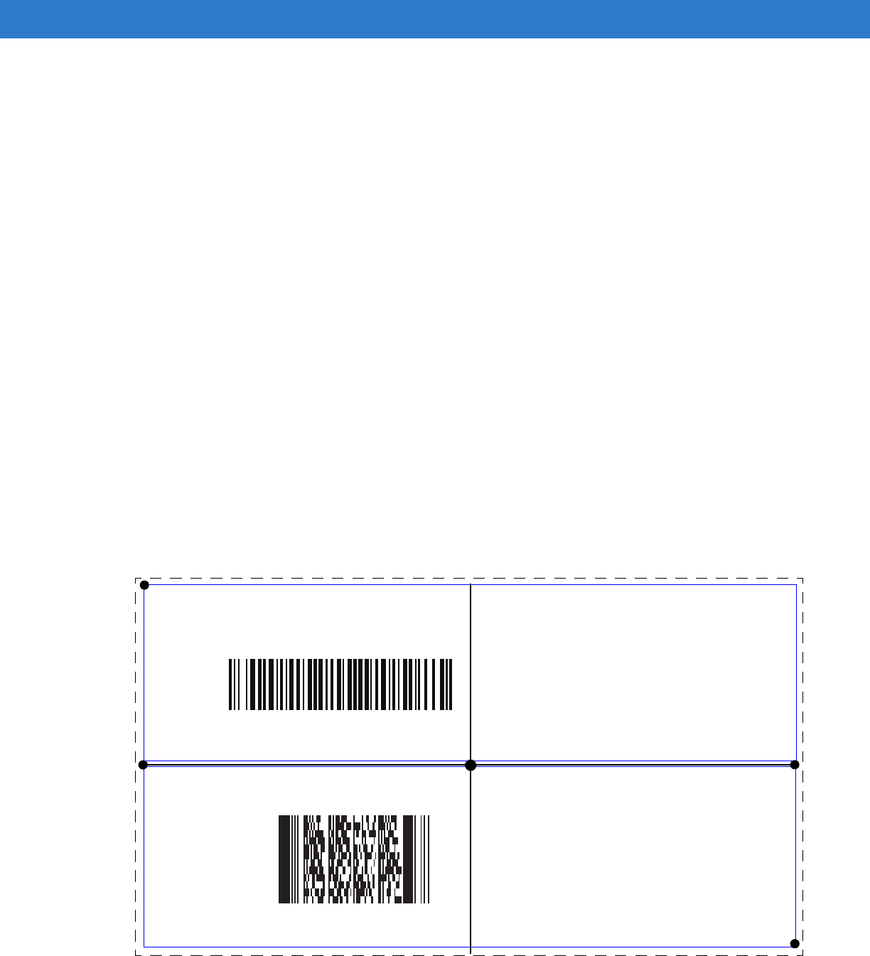
User Preferences & Miscellaneous Digital Scanner Options 5 - 27
Example 2a
To decode a Code128 (Code Type=8) on the top half of the image and a PDF417 (Code Type=15) on the bottom
half of the image, as in Figure 5-2, program the expression as follows:
The expression in decimal is (formatted for readability):
2 C 2 0 8 R 4 0 0 100 50 ; C 2 0 15 R 4 0 50 100 100 ;
To program the expression via scanning parameters the sequence is:
[MultiCode-Expression] 02 C 02 00 08 R 04 00 00 64 32 ; C 02 00 0F R 04 00 32 64 64 ; [End Of Message]
To program the expression via host command (SSI/SNAPI) the sequence is:
0x02 0x43 0x02 0x00 0x08 0x52 0x04 0x00 0x00 0x64 0x32 0x3B 0x43 0x02 0x00 0x0F 0x52 0x04 0x00 0x32
0x64 0x64 0x3B
Example 2b
In Figure 5-2, if the bottom PDF417 bar code must transmit first, reverse the sequence of the two bar codes:
The expression in decimal is (formatted for readability):
2 C 2 0 15 R 4 0 50 100 100 ; C 2 0 8 R 4 0 0 100 50 ;
To program the expression via scanning parameters the sequence is:
[MultiCode-Expression] 02 C 02 00 0F R 04 00 32 64 64 ; C 02 00 08 R 04 00 00 64 32 ; [End Of Message]
To program the expression via host command (SSI/SNAPI) the sequence is:
0x02 0x43 0x02 0x00 0x0F 0x52 0x04 0x00 0x32 0x64 0x64 0x3B 0x43 0x02 0x00 0x08 0x52 0x04 0x00 0x00
0x64 0x32 0x3B
Figure 5-2
Multicode Expression Example 2
PDF417 Code
(0,0)
Code 128 Code
(0,50)
(160,100)
(100,50)
50%
0%
100%
0% 50% 100%
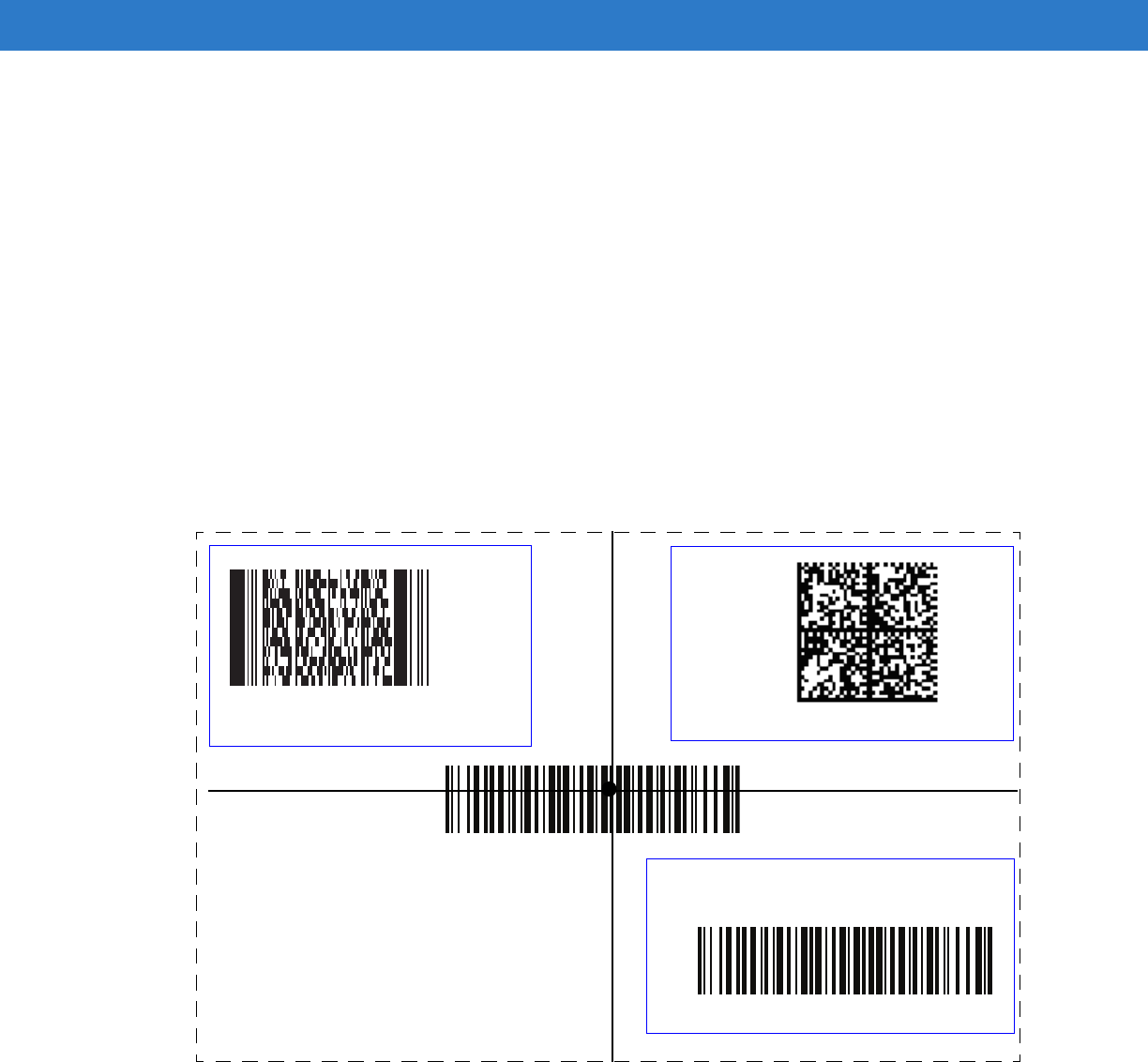
5 - 28 Symbol DS6878 Product Reference Guide
Example 3
To decode the set of three bar codes while excluding the center Code 128 bar code, as in Figure 5-3, the
expression is:
The expression in decimal is (formatted for readability):
3 C 2 0 15 R 4 0 0 50 50 ; C 2 [F0 24] R 4 70 0 100 40 ; C 2 0 8 R 4 65 60 100 100 ;
To program the expression via scanning parameters the sequence is:
[MultiCode-Expression] 03 C 02 00 0F R 04 00 00 32 32 ; C 02 F0 24 R 04 46 00 64 28 ;
C 02 00 08 R 04 41 3C 64 64 ; [End Of Message]
To program the expression via host command (SSI/SNAPI) the sequence is:
0x03 0x43 0x02 0x00 0x0F 0x52 0x04 0x00 0x00 0x32 0x32 0x3B 0x43 0x02 0xF0 0x24 0x52 0x04 0x46 0x00
0x64 0x28 0x3B 0x43 0x02 0x00 0x08 0x52 0x04 0x41 0x3C 0x64 0x64 0x3B
Figure 5-3
Multicode Expression Example 3
40%
65%
40%
40%
PDF417 Code
Code 128 Code
Data Matrix Code
Code 128 Code
70%
60%
(70,0)
(100,40)
(100,100)
(0,0)
(40,40)
(65,60)
50%
0%
100%
0% 50% 100%

User Preferences & Miscellaneous Digital Scanner Options 5 - 29
Multicode Mode Concatenation
Parameter # F1h, CDh
Enable this parameter to transmit multiple decoded bar codes, as specified by the Multicode Expression, as one
bar code. Use the Multicode Concatenation Symbology parameter to specify how the concatenated bar codes
transmit.
Disable this to transmit decoded bar codes separately.
NOTE When using Multicode Mode Concatenation, disable Transmit Code ID Character on page 5-33 and check
digits.
Enable Multicode Mode Concatenation
(01h)
*Disable Multicode Mode Concatenation
(00h)

5 - 30 Symbol DS6878 Product Reference Guide
Multicode Concatenation Symbology
Parameter # F1h, D2h
Use this parameter to specify how to transmit the concatenated bar codes decoded as specified by the Multicode
Expression. Multicode Mode Concatenation must be enabled to use this option.
Concatenation as Code 128
(01h)
*Concatenation as PDF417
(02h)
Concatenation as Data Matrix
(03h)
Concatenation as Maxicode
(04h)

User Preferences & Miscellaneous Digital Scanner Options 5 - 31
Multicode Troubleshooting
Troubleshooting Multicode Expression Programming
Use the following suggestions if encountering problems programming a multicode expression:
•
Ensure the expression is valid. Invalid expressions are rejected during programming. When an expression is
rejected the previous expression remains intact. If after programming the expression the digital scanner can
still decode any bar code, the expression was possibly rejected.
•
When programming the multicode expression via parameter bar code, the digital scanner generates beeps. If
any of the following beeps do not sound during programming, an error occurred (see Table 2-1 on page 2-1
and Table 2-2 on page 2-3 for error indicators):
•Scanning the Multicode Expression bar code produces a two-tone (same pitch) beep.
•Scanning each value of the expression produces a two-tone (same pitch) beep.
•Scanning the End Of Message bar code produces a four-tone (high-low-high-low) beep.
•
Check the expression for syntax errors.
•
Try programming a simple expression to ensure the syntax is correct. See Examples of Simple Multicode
Expressions.
•
Review Defining Multicode Expression Notes on page 5-25 for additional hints.
Troubleshooting Multicode Mode Scanning and Decoding
Use the following suggestions if encountering problems using multicode mode:
•
If the digital scanner appears to decode any single bar code instead of the intended multiple bar codes,
ensure you enabled Multicode Mode on page 5-23. Programming the multicode expression does not enable
multicode mode.
•
When specifying Region, ensure:
•Coordinates are within range the 0-100 decimal (or 0x00 - 0x64 hexadecimal).
•Top, Left is above Bottom, Right. Top, Left is 0,0 (0x00, 0x00 hexadecimal), and Bottom, Right is 100,100
(0x64, 0x64 hexadecimal).
•Regions for two or more bar codes do not overlap.
•
When specifying Code Type ensure the digital scanner supports the code type. Try decoding a single bar
code without using multicode. If it does not decode try enabling the bar code type. See Chapter 14,
Symbologies.
•
Experiment with simpler expressions, then add to it until you discover the source of the error. For example try
the simplest expression (see Examples of Simple Multicode Expressions) and make sure you can scan a
single bar code. If so, extend the expression by adding a second bar code, specifying a region, or specifying
the code type. Verify that the digital scanner can decode this new expression. Continue adding to the
expression until it fails to decode as expected, indicating the source of the error.
•
Review Defining Multicode Expression Notes on page 5-25 for additional hints.

5 - 32 Symbol DS6878 Product Reference Guide
Examples of Simple Multicode Expressions
The simplest multicode expression is:
•
One bar code of any type, anywhere in the image.
•
To program this use: [MultiCode-Expression] 01 ; [End Of Message]
Another simple multicode expression is:
•
One Code 128 bar code, anywhere in the image.
•
To program this use: [MultiCode-Expression] 01 C 02 00 08 ; [End Of Message]
User Preferences & Miscellaneous Digital Scanner Options 5 - 33
Miscellaneous Scanner Parameters
Transmit Code ID Character
Parameter # 2Dh
A Code ID character identifies the code type of a scanned bar code. This is useful when decoding more than one
code type. In addition to any single character prefix already selected, the Code ID character is inserted between
the prefix and the decoded symbol.
Select no Code ID character, a Symbol Code ID character, or an AIM Code ID character. For Code ID Characters,
see Symbol Code Identifiers on page B-1 and AIM Code Identifiers on page B-3.
NOTE If you enable Symbol Code ID Character or AIM Code ID Character, and enable Transmit “No Read”
Message on page 5-37, the digital scanner appends the code ID for Code 39 to the NR message.
Symbol Code ID Character
(02h)
AIM Code ID Character
(01h)
*None
(00h)
5 - 34 Symbol DS6878 Product Reference Guide
Prefix/Suffix Values
Key Category Parameter # P = 63h, S1 = 62h, S2 = 64h
Decimal Value Parameter # P = 69h, S1 = 68h, S2 = 6Ah
You can append a prefix and/or one or two suffixes to scan data for use in data editing. To set a value for a prefix or
suffix, scan a four-digit number (i.e., four bar codes from Appendix D, Numeric Bar Codes) that corresponds to that
value. See Table E-1 on page E-1 for the four-digit codes.
When using host commands to set the prefix or suffix, set the key category parameter to 1, then set the 3-digit
decimal value. See Table E-1 on page E-1 for the four-digit codes.
To correct an error or change a selection, scan Cancel on page D-2.
NOTE To use Prefix/Suffix values, first set the Scan Data Transmission Format on page 5-35.
Scan Prefix
(07h)
Scan Suffix 1
(06h)
Scan Suffix 2
(08h)
Data Format Cancel
User Preferences & Miscellaneous Digital Scanner Options 5 - 35
Scan Data Transmission Format
Parameter # EBh
To change the scan data format, scan one of the following eight bar codes corresponding to the desired format.
To set values for the prefix and/or suffix, see Prefix/Suffix Values on page 5-34.
NOTE If using this parameter do not use ADF rules to set the prefix/suffix.
*Data As Is
(00h)
<DATA> <SUFFIX 1>
(01h)
<DATA> <SUFFIX 2>
(02h)
<DATA> <SUFFIX 1> <SUFFIX 2>
(03h)
<PREFIX> <DATA >
(04h)
5 - 36 Symbol DS6878 Product Reference Guide
FN1 Substitution Values
Key Category Parameter # 67h
Decimal Value Parameter # 6Dh
The Wedge and USB HID Keyboard hosts support a FN1 Substitution feature. Enabling this substitutes any FN1
character (0x1b) in an EAN128 bar code with a value. This value defaults to 7013 (Enter Key).
When using host commands to set the FN1 substitution value, set the key category parameter to 1, then set the
3-digit keystroke value. See the ASCII Character Set table for the current host interface for the desired value.
To select a FN1 substitution value via bar code menus:
1. Scan the bar code below.
2. Locate the keystroke desired for FN1 Substitution in the ASCII Character Set table for the current host
interface. Enter the 4-digit ASCII Value by scanning each digit in Appendix D, Numeric Bar Codes.
To correct an error or change the selection, scan Cancel.
To enable FN1 substitution for USB HID keyboard, scan the Enable FN1 Substitution bar code on page -36.
Scan Data Transmission Format (continued)
<PREFIX> <DATA> <SUFFIX 1>
(05h)
<PREFIX> <DATA> <SUFFIX 2>
(06h)
<PREFIX> <DATA> <SUFFIX 1> <SUFFIX 2>
(07h)
Set FN1 Substitution Value

User Preferences & Miscellaneous Digital Scanner Options 5 - 37
Transmit “No Read” Message
Parameter # 5Eh
Scan a bar code below to select whether or not to transmit a No Read message. Enable this to transmit the
characters NR when a successful decode does not occur before trigger release or the Decode Session Timeout
expires. See Decode Session Timeout on page 5-19. Disable this to send nothing to the host if a symbol does not
decode.
NOTE If you enable Transmit No Read, and also enable Symbol Code ID Character or AIM Code ID Character
for Transmit Code ID Character on page 5-33, the digital scanner appends the code ID for Code 39 to the
NR message.
Enable No Read
(01h)
*Disable No Read
(00h)

5 - 38 Symbol DS6878 Product Reference Guide

Chapter 6 USB Interface
Introduction
This chapter provides instructions for programming the cradle to interface with a USB host. The digital scanner
cradle connects directly to a USB host, or a powered USB hub. The USB host can power the cradle and recharge
the digital scanner battery, but this charging method has limitations. See Using the USB Interface to Supply Power
on page 1-7.
Throughout the programming bar code menus, default values are indicated with asterisks (*).
*North American Standard USB Keyboard Feature/Option
* Indicates Default
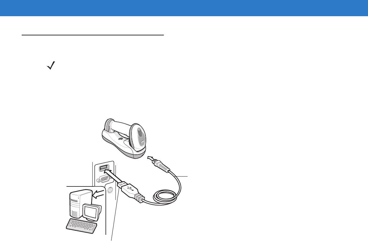
6 - 2 Symbol DS6878 Product Reference Guide
Connecting a USB Interface
Figure 6-1
USB Connection
The digital scanner cradle connects with USB capable hosts including:
•
Desktop PCs and Notebooks
•
Apple™ iMac, G4, iBooks (North America only)
•
IBM SurePOS terminals
•
Sun, IBM, and other network computers that support more than one keyboard.
The following operating systems support the digital scanner cradle through USB:
•
Windows 98, 2000, ME, XP
•
MacOS 8.5 and above
•
IBM 4690 OS.
The digital scanner cradle also interfaces with other USB hosts which support USB Human Interface Devices
(HID). For more information on USB technology, hosts, and peripheral devices, visit www.symbol.com/usb.
To connect the USB interface:
1. Attach the modular connector of the USB interface cable to the host port on the bottom of the digital scanner
cradle (see Connecting the Cradle on page 1-6).
NOTE See Chapter 4, Radio Communications for information about digital scanner/cradle pairing and wireless
communication
The digital scanner must be connected to the cradle for the host parameter setting to take effect. When
the digital scanner is not connected to a cradle, and a host parameter bar code is scanned, a long
low/long high beep sequence sounds.
Interface Cable
USB Series A Connector
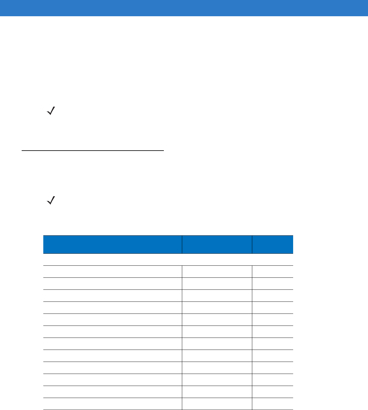
USB Interface 6 - 3
2. Plug the series A connector in the USB host or hub, or plug the Plus Power connector in an available port of
the IBM SurePOS terminal.
3. Select the USB device type by scanning the appropriate bar code from USB Device Type on page 6-4.
4. On first installation when using Windows, the software prompts to select or install the Human Interface Device
driver. To install this driver, provided by Windows, click Next through all the choices and click Finished on the
last choice. The cradle powers up during this installation.
5. To modify any other parameter options, scan the appropriate bar codes in this chapter.
If problems occur with the system, see Troubleshooting on page 3-2.
USB Parameter Defaults
Table 6-1 lists the defaults for USB host parameters. If any option needs to be changed, scan the appropriate bar
code(s) provided in the Parameter Descriptions section beginning on page 6-4.
NOTE Interface cables vary depending on configuration. The connectors illustrated in Figure 6-1 are examples
only. The connectors may be different than those illustrated, but the steps to connect the digital scanner
cradle remain the same.
NOTE See Appendix A, Standard Default Parameters for all user preferences, hosts, symbologies, and
miscellaneous default parameters.
Table 6-1
USB Host Default Table
Parameter Default Page
Number
USB Host Parameters
USB Device Type HID Keyboard Emulation
6-4
USB Country Keyboard Types (Country Codes) North American
6-5
USB Keystroke Delay No Delay
6-7
USB CAPS Lock Override Disable
6-7
USB Ignore Unknown Characters Send
6-8
Emulate Keypad Disable
6-9
USB FN1 Substitution Disable
6-9
Function Key Mapping Disable
6-9
Simulated Caps Lock Disable
6-10
Convert Case No Case Conversion
6-10
Ignore Beep Disable
6-11
Ignore Bar Code Configuration Disable
6-11
6 - 4 Symbol DS6878 Product Reference Guide
USB Host Parameters
USB Device Type
Select the desired USB device type.
NOTE When changing USB Device Types, the digital scanner automatically restarts. The digital scanner issues
the standard startup beep sequences.
*HID Keyboard Emulation
IBM Table Top USB
IBM Hand-Held USB
USB OPOS Handheld

USB Interface 6 - 5
USB Country Keyboard Types (Country Codes)
Scan the bar code corresponding to the keyboard type. This setting applies only to the USB HID Keyboard
Emulation device.
NOTE When changing USB country keyboard types the digital scanner automatically resets. The digital scanner
issues the standard startup beep sequences.
*North American Standard USB Keyboard
German Windows
French Windows
French Canadian Windows 95/98
French Canadian Windows 2000/XP
Spanish Windows

6 - 6 Symbol DS6878 Product Reference Guide
USB Country Keyboard Types (Country Codes continued)
Italian Windows
Swedish Windows
UK English Windows
Japanese Windows (ASCII)
Portuguese-Brazilian Windows
USB Interface 6 - 7
USB Keystroke Delay
This parameter sets the delay, in milliseconds, between emulated keystrokes. Scan a bar code below to increase
the delay when hosts require a slower transmission of data.
USB CAPS Lock Override
This option applies only to the HID Keyboard Emulation device. When enabled, the case of the data is preserved
regardless of the state of the caps lock key. This setting is always enabled for the “Japanese, Windows (ASCII)”
keyboard type and can not be disabled.
*No Delay
Medium Delay (20 msec)
Long Delay (40 msec)
Override Caps Lock Key
(Enable)
*Do Not Override Caps Lock Key
(Disable)

6 - 8 Symbol DS6878 Product Reference Guide
USB Ignore Unknown Characters
This option applies only to the HID Keyboard Emulation device and IBM device. Unknown characters are
characters the host does not recognize. When Send Bar Codes With Unknown Characters is selected, all bar
code data is sent except for unknown characters, and no error beeps sound. When Do Not Send Bar Codes With
Unknown Characters is selected, bar code data is sent up to the first unknown character, then the digital scanner
issues an error beep.
Emulate Keypad
When enabled, all characters are sent as ASCII sequences over the numeric keypad. For example ASCII A would
be sent as “ALT make” 0 6 5 “ALT Break.”
*Send Bar Codes with Unknown Characters
Do Not Send Bar Codes with Unknown Characters
*Disable Keypad Emulation
Enable Keypad Emulation

USB Interface 6 - 9
USB Keyboard FN 1 Substitution
This option applies only to the USB HID Keyboard Emulation device. When enabled, this allows replacement of
any FN 1 characters in an EAN 128 bar code with a Key Category and value chosen by the user (see FN1
Substitution Values on page 5-36 to set the Key Category and Key Value).
Function Key Mapping
ASCII values under 32 are normally sent as a control-key sequences (see Table 6-2 on page 6-12). When this
parameter is enabled, the keys in bold are sent in place of the standard key mapping. Table entries that do not
have a bold entry remain the same whether or not this parameter is enabled.
Enable FN1 Substitution
*Disable FN1 Substitution
*Disable Function Key Mapping
Enable Function Key Mapping
6 - 10 Symbol DS6878 Product Reference Guide
Simulated Caps Lock
When enabled, the digital scanner inverts upper and lower case characters on the digital scanner bar code as if the
Caps Lock state is enabled on the keyboard. This inversion is done regardless of the current state of the
keyboard’s Caps Lock state.
Convert Case
When enabled, the digital scanner converts all bar code data to the selected case.
*Disable Simulated Caps Lock
Enable Simulated Caps Lock
*No Case Conversion
Convert All to Upper Case
Convert All to Lower Case
USB Interface 6 - 11
Optional USB Parameters
If you configure the digital scanner and find the settings were not saved, or changed, when the system is restarted
scan the bar codes that follow to override USB interface defaults.
Scan a bar code below after setting defaults and before configuring the digital scanner.
Ignore Beep
The host can send a beep request to the digital scanner. When this parameter is enabled, the request is not sent to
the attached digital scanner. All directives are still acknowledged to the USB host as if it were processed.
Ignore Bar Code Configuration
The host has the ability to enable/disable code types. When this parameter is enabled, the request is not sent to
the attached digital scanner. All directives are still acknowledged to the USB host as if it were processed.
*Disable
Enable
*Disable
Enable

6 - 12 Symbol DS6878 Product Reference Guide
ASCII Character Set for USB
Table 6-2
ASCII Character Set for USB
ASCII Value
Full ASCII
Code 39 Encode
Character
Keystroke
1000 %U CTRL 2
1001 $A CTRL A
1002 $B CTRL B
1003 $C CTRL C
1004 $D CTRL D
1005 $E CTRL E
1006 $F CTRL F
1007 $G CTRL G
1008 $H CTRL H/
BACKSPACE
1
1009 $I CTRL I/
HORIZONTAL TAB
1
1010 $J CTRL J
1011 $K CTRL K
1012 $L CTRL L
1013 $M CTRL M/
ENTER
1
1014 $N CTRL N
1015 $O CTRL O
1016 $P CTRL P
1017 $Q CTRL Q
1018 $R CTRL R
1019 $S CTRL S
1020 $T CTRL T
1021 $U CTRL U
1022 $V CTRL V
1023 $W CTRL W
1024 $X CTRL X
1
The keystroke in bold is sent only if the “Function Key Mapping” is enabled.
Otherwise, the unbolded keystroke is sent.

USB Interface 6 - 13
1025 $Y CTRL Y
1026 $Z CTRL Z
1027 %A CTRL [/
ESC
1
1028 %B CTRL \
1029 %C CTRL ]
1030 %D CTRL 6
1031 %E CTRL -
1032 Space Space
1033 /A !
1034 /B “
1035 /C #
1036 /D $
1037 /E %
1038 /F &
1039 /G ‘
1040 /H (
1041 /I )
1042 /J *
1043 /K +
1044 /L ,
1045 - -
1046 . .
1047 /O /
1048 0 0
1049 1 1
1050 2 2
1051 3 3
1052 4 4
Table 6-2
ASCII Character Set for USB (Continued)
ASCII Value
Full ASCII
Code 39 Encode
Character
Keystroke
1
The keystroke in bold is sent only if the “Function Key Mapping” is enabled.
Otherwise, the unbolded keystroke is sent.

6 - 14 Symbol DS6878 Product Reference Guide
1053 5 5
1054 6 6
1055 7 7
1056 8 8
1057 9 9
1058 /Z :
1059 %F ;
1060 %G <
1061 %H =
1062 %I >
1063 %J ?
1064 %V @
1065 A A
1066 B B
1067 C C
1068 D D
1069 E E
1070 F F
1071 G G
1072 H H
1073 I I
1074 J J
1075 K K
1076 L L
1077 M M
1078 N N
1079 O O
1080 P P
Table 6-2
ASCII Character Set for USB (Continued)
ASCII Value
Full ASCII
Code 39 Encode
Character
Keystroke
1
The keystroke in bold is sent only if the “Function Key Mapping” is enabled.
Otherwise, the unbolded keystroke is sent.

USB Interface 6 - 15
1081 Q Q
1082 R R
1083 S S
1084 T T
1085 U U
1086 V V
1087 W W
1088 X X
1089 Y Y
1090 Z Z
1091 %K [
1092 %L \
1093 %M ]
1094 %N ^
1095 %O _
1096 %W `
1097 +A a
1098 +B b
1099 +C c
1100 +D d
1101 +E e
1102 +F f
1103 +G g
1104 +H h
1105 +I i
1106 +J j
1107 +K k
1108 +L l
Table 6-2
ASCII Character Set for USB (Continued)
ASCII Value
Full ASCII
Code 39 Encode
Character
Keystroke
1
The keystroke in bold is sent only if the “Function Key Mapping” is enabled.
Otherwise, the unbolded keystroke is sent.

6 - 16 Symbol DS6878 Product Reference Guide
1109 +M m
1110 +N n
1111 +O o
1112 +P p
1113 +Q q
1114 +R r
1115 +S s
1116 +T t
1117 +U u
1118 +V v
1119 +W w
1120 +X x
1121 +Y y
1122 +Z z
1123 %P {
1124 %Q |
1125 %R }
1126 %S ~
Table 6-2
ASCII Character Set for USB (Continued)
ASCII Value
Full ASCII
Code 39 Encode
Character
Keystroke
1
The keystroke in bold is sent only if the “Function Key Mapping” is enabled.
Otherwise, the unbolded keystroke is sent.

USB Interface 6 - 17
Table 6-3
USB ALT Key Character Set
ALT Keys Keystroke
2064 ALT 2
2065 ALT A
2066 ALT B
2067 ALT C
2068 ALT D
2069 ALT E
2070 ALT F
2071 ALT G
2072 ALT H
2073 ALT I
2074 ALT J
2075 ALT K
2076 ALT L
2077 ALT M
2078 ALT N
2079 ALT O
2080 ALT P
2081 ALT Q
2082 ALT R
2083 ALT S
2084 ALT T
2085 ALT U
2086 ALT V
2087 ALT W
2088 ALT X
2089 ALT Y
2090 ALT Z

6 - 18 Symbol DS6878 Product Reference Guide
Table 6-4
USB GUI Key Character Set
GUI Key Keystroke
3000 Right Control Key
3048 GUI 0
3049 GUI 1
3050 GUI 2
3051 GUI 3
3052 GUI 4
3053 GUI 5
3054 GUI 6
3055 GUI 7
3056 GUI 8
3057 GUI 9
3065 GUI A
3066 GUI B
3067 GUI C
3068 GUI D
3069 GUI E
3070 GUI F
3071 GUI G
3072 GUI H
3073 GUI I
3074 GUI J
3075 GUI K
3076 GUI L
3077 GUI M
3078 GUI N
3079 GUI O
3080 GUI P
Note:
GUI Shift Keys - The Apple
™
iMac keyboard has an apple key on either side of the
space bar. Windows-based systems have a GUI key to the left of the left ALT key, and to the
right of the right ALT key.
USB Interface 6 - 19
3081 GUI Q
3082 GUI R
3083 GUI S
3084 GUI T
3085 GUI U
3086 GUI V
3087 GUI W
3088 GUI X
3089 GUI Y
3090 GUI Z
Table 6-5
USB F Key Character Set
F Keys Keystroke
5001 F1
5002 F2
5003 F3
5004 F4
5005 F5
5006 F6
5007 F7
5008 F8
5009 F9
5010 F10
5011 F11
5012 F12
5013 F13
5014 F14
5015 F15
Table 6-4
USB GUI Key Character Set (Continued)
GUI Key Keystroke
Note:
GUI Shift Keys - The Apple
™
iMac keyboard has an apple key on either side of the
space bar. Windows-based systems have a GUI key to the left of the left ALT key, and to the
right of the right ALT key.

6 - 20 Symbol DS6878 Product Reference Guide
5016 F16
5017 F17
5018 F18
5019 F19
5020 F20
5021 F21
5022 F22
5023 F23
5024 F24
Table 6-6
USB Numeric Keypad Character Set
Numeric Keypad Keystroke
6042 *
6043 +
6044 undefined
6045 -
6046 .
6047 /
6048 0
6049 1
6050 2
6051 3
6052 4
6053 5
6054 6
6055 7
6056 8
6057 9
6058 Enter
6059 Num Lock
Table 6-5
USB F Key Character Set (Continued)
F Keys Keystroke

USB Interface 6 - 21
Table 6-7
USB Extended Keypad Character Set
Extended Keypad Keystroke
7001 Break
7002 Delete
7003 PgUp
7004 End
7005 Pg Dn
7006 Pause
7007 Scroll Lock
7008 Backspace
7009 Tab
7010 Print Screen
7011 Insert
7012 Home
7013 Enter
7014 Escape
7015 Up Arrow
7016 Down Arrow
7017 Left Arrow
7018 Right Arrow

6 - 22 Symbol DS6878 Product Reference Guide

Chapter 7 RS-232 Interface
Introduction
This chapter provides instructions for programming the cradle to interface with an RS-232 host interface. The
RS-232 interface is used to attach the scanner cradle to point-of-sale devices, host computers, or other devices
with an available RS-232 port (i.e., COM port).
If the particular host is not listed in Table 7-2, set the communication parameters to match the host device. Refer to
the documentation for the host device.
Throughout the programming bar code menus, default values are indicated with asterisks (*).
NOTE This digital scanner uses TTL RS-232 signal levels, which interface with most system architectures. For
system architectures requiring RS-232C signal levels, Motorola offers different cables providing the TTL to
RS-232C conversion. Contact Motorola Enterprise Mobility Support for more information.
*Baud Rate 38,400 Feature/Option
* Indicates Default
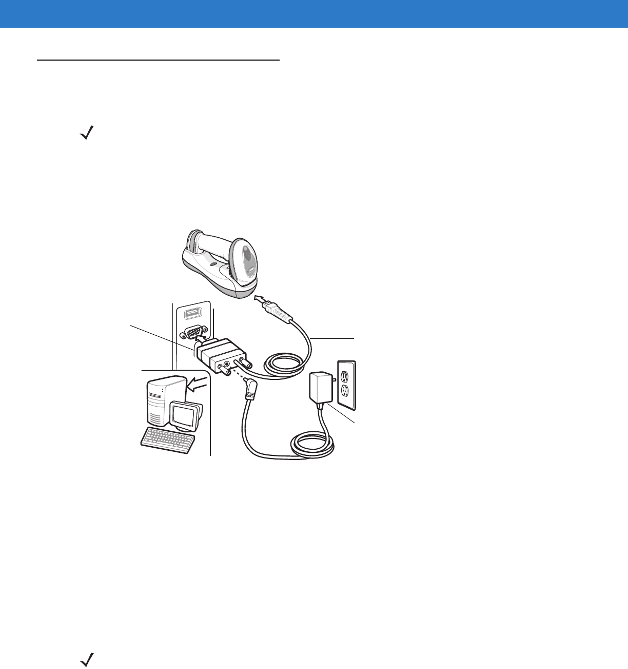
7 - 2 Symbol DS6878 Product Reference Guide
Connecting an RS-232 Interface
This connection is made directly from the cradle to the host computer.
Figure 7-1
RS-232 Direct Connection
To connect the RS-232 interface:
1. Attach the modular connector of the RS-232 interface cable to the host port on the bottom of the scanner
cradle (see Connecting the Cradle on page 1-6).
2. Connect the other end of the RS-232 interface cable to the serial port on the host.
3. Connect the power supply to the serial connector end of the RS-232 interface cable. Plug the power supply
into an appropriate outlet.
4. Select the RS-232 host type by scanning the appropriate bar code from RS-232 Host Types on page 7-6.
5. To modify any other parameter options, scan the appropriate bar codes in this chapter.
If a power supply is used, disconnect the power supply before changing host cables or the cradle may not
recognize the new host.
NOTE See Chapter 4, Radio Communications for information about digital scanner/cradle pairing and wireless
communication
The digital scanner must be connected to the cradle for the host parameter setting to take effect. When
the digital scanner is not connected to a cradle, and a host parameter bar code is scanned, a long
low/long high beep sequence sounds.
Interface Cable
Serial Port
Connection
to Host
Power Supply
NOTE Interface cables vary depending on configuration. The connectors illustrated in Figure 7-1 are examples
only. The connectors may be different than those illustrated, but the steps to connect the cradle remain the
same.
RS-232 Interface 7 - 3
RS-232 Parameter Defaults
Table 7-1 lists the defaults for RS-232 host parameters. If any option needs to be changed, scan the appropriate
bar code(s) provided in the Parameter Descriptions section beginning on page 7-4.
NOTE See Appendix A, Standard Default Parameters for all user preferences, hosts, symbologies, and
miscellaneous default parameters.
Table 7-1
RS-232 Host Default Table
Parameter Default Page
Number
RS-232 Host Parameters
RS-232 Host Types Standard
7-6
Baud Rate 9600
7-8
Parity Type None
7-9
Stop Bit Select 1 Stop Bit
7-9
Data Bits (ASCII Format) 8-Bit
7-10
Check Receive Errors Enable
7-11
Hardware Handshaking None
7-11
Software Handshaking None
7-13
Host Serial Response Time-out 2 sec
7-15
RTS Line State Low RTS
7-16
Beep on <BEL> Disable
7-16
Intercharacter Delay 0 msec
7-17
Nixdorf Beep/LED Options Normal Operation
7-18
Ignore Unknown Characters Send Bar Code
7-18
7 - 4 Symbol DS6878 Product Reference Guide
RS-232 Host Parameters
Various RS-232 hosts are set up with their own parameter default settings (Table 7-2). Selecting the ICL, Fujitsu,
Wincor-Nixdorf Mode A, Wincor-Nixdorf Mode B, Olivetti, Omron, or terminal sets the defaults listed below.
Table 7-2
Terminal Specific RS-232
Parameter ICL Fujitsu
Wincor-
Nixdorf
Mode A
Wincor-
Nixdorf Mode
B/OPOS/JPOS
Olivetti Omron CUTE
Transmit Code ID
Yes Yes Yes Yes Yes Yes Yes
Data Transmission
Format
Data/Suffix Data/Suffix Data/Suffix Data/Suffix Prefix/Data/
Suffix Data/Suffix Prefix/Data/
Suffix
Suffix
CR (1013) CR (1013) CR (1013) CR (1013) ETX (1002) CR (1013) CR (1013)
ETX (1002)
Baud Rate
9600 9600 9600 9600 9600 9600 9600
Parity
Even None Odd Odd Even None Even
Hardware
Handshaking
RTS/CTS
Option 3 None RTS/CTS
Option 3 RTS/CTS
Option 3 None None None
Software
Handshaking
None None None None ACK/NAK None None
Serial Response
Time-out
9.9 Sec. 2 Sec. 9.9 Sec. 9.9 Sec. 9.9 Sec. 9.9 Sec. 9.9 Sec.
Stop Bit Select
One One One One One One One
ASCII Format
8-Bit 8-Bit 8-Bit 8-Bit 7-Bit 8-Bit 7-Bit
Beep On <BEL>
Disable Disable Disable Disable Disable Disable Disable
RTS Line State
High Low Low Low = No data to
send Low High High
Prefix
None None None None STX (1003) None STX (1003)
In the Nixdorf Mode B, if CTS is low, scanning is disabled. When CTS is high, scanning is enabled.
If you scan Nixdorf Mode B without connecting the digital scanner to the proper host, it may appear unable
to scan. If this happens, scan a different RS-232 host type within 5 seconds of cycling power to the digital
scanner.
The CUTE host disables all parameter scanning, including Set Defaults. If you inadvertently select CUTE,
scan
*Enable Parameter Bar Code Scanning (01h) on page 5-5
, then change the host selection.

RS-232 Interface 7 - 5
RS-232 Host Parameters (continued)
Selecting the ICL, Fujitsu, Wincor-Nixdorf Mode A, Wincor-Nixdorf Mode B, OPOS terminal enables the
transmission of code ID characters listed in Table 7-3 below. These code ID characters are not programmable and
are separate from the Transmit Code ID feature. The Transmit Code ID feature should not be enabled for these
terminals.
Table 7-3
Terminal Specific Code ID Characters
Code Type ICL Fujitsu
Wincor-
Nixdorf
Mode A
Wincor-Nixdorf
Mode B/
OPOS/JPOS
Olivetti Omron CUTE
UPC-A
AAA A AAA
UPC-E
EEC C CENone
EAN-8/JAN-8
FF FF B B B FF None
EAN-13/JAN-13
FFA A AF A
Code 39
C <len> None M M M <len> C <len> 3
Code 39 Full ASCII
None None M M None None 3
Codabar
N <len> None N N N <len> N <len> None
Code 128
L <len> None K K K <len> L <len> 5
I 2 of 5
I <len> None I I I <len> I <len> 1
Code 93
None None L L L <len> None None
D 2 of 5
H <len> None H H H <len> H <len> 2
GS1-128
L <len> None P P P <len> L <len> 5
MSI
None None O O O <len> None None
Bookland EAN
FFA A AF None
Trioptic
None None None None None None None
Code 11
None None None None None None None
IATA
H<len> None H H None None 2
Code 32
None None None None None None None
GS1 Databar
Variants
None None E E None None None
PDF417
None None Q Q None None 6
Datamatrix
None None None None None None 4
QR Codes
None None None None None None 7
Aztec/Aztec Rune
None None None None None None 8
7 - 6 Symbol DS6878 Product Reference Guide
RS-232 Host Types
To select an RS-232 host interface, scan one of the following bar codes.
*Standard RS-232
ICL RS-232
Wincor-Nixdorf RS-232 Mode A
Wincor-Nixdorf RS-232 Mode B
Olivetti ORS4500

RS-232 Interface 7 - 7
Omron
OPOS/JPOS
Fujitsu RS-232
SITA/CUTE
7 - 8 Symbol DS6878 Product Reference Guide
Baud Rate
Baud rate is the number of bits of data transmitted per second. Set the digital scanner's baud rate to match the
baud rate setting of the host device. Otherwise, data may not reach the host device or may reach it in distorted
form.
Baud Rate 600
Baud Rate 1200
Baud Rate 2400
Baud Rate 4800
*Baud Rate 9600
Baud Rate 19,200
Baud Rate 38,400
RS-232 Interface 7 - 9
Parity
A parity check bit is the most significant bit of each ASCII coded character. Select the parity type according to host
device requirements.
•
Select Odd parity and the parity bit value is set to 0 or 1, based on data, to ensure that an odd number of 1
bits are contained in the coded character.
•
Select Even parity and the parity bit value is set to 0 or 1, based on data, to ensure that an even number of 1
bits are contained in the coded character.
•
Select Mark parity and the parity bit is always 1.
•
Select Space parity and the parity bit is always 0.
•
Select None when no parity bit is required.
Stop Bit Select
The stop bit(s) at the end of each transmitted character marks the end of transmission of one character and
prepares the receiving device for the next character in the serial data stream. The number of stop bits selected
Odd
Even
Mark
Space
*None

7 - 10 Symbol DS6878 Product Reference Guide
(one or two) depends on the number the receiving terminal is programmed to accommodate. Set the number of
stop bits to match host device requirements.
Data Bits (ASCII Format)
This parameter allows the digital scanner to interface with devices requiring a 7-bit or 8-bit ASCII protocol.
*1 Stop Bit
2 Stop Bits
7-Bit
*8-Bit

RS-232 Interface 7 - 11
Check Receive Errors
Select whether or not the parity, framing, and overrun of received characters are checked. The parity value of
received characters is verified against the parity parameter selected above.
Hardware Handshaking
The data interface consists of an RS-232 port designed to operate either with or without the hardware handshaking
lines, Request to Send (RTS), and Clear to Send (CTS).
If Standard RTS/CTS handshaking is not selected, scan data is transmitted as it becomes available. If Standard
RTS/CTS handshaking is selected, scan data is transmitted according to the following sequence:
•
The digital scanner reads the CTS line for activity. If CTS is asserted, the digital scanner waits up to Host
Serial Response Time-out for the host to de-assert the CTS line. If, after Host Serial Response Time-out, the
CTS line is still asserted, the digital scanner sounds a transmit error, and any scanned data is lost.
•
When the CTS line is de-asserted, the digital scanner asserts the RTS line and waits up to Host Serial
Response Time-out for the host to assert CTS. When the host asserts CTS, data is transmitted. If, after Host
Serial Response Time-out, the CTS line is not asserted, the digital scanner sounds a transmit error, and
discards the data.
•
When data transmission is complete, the digital scanner de-asserts RTS 10 msec after sending the last
character.
•
The host should respond by negating CTS. The digital scanner checks for a de-asserted CTS upon the next
transmission of data.
During the transmission of data, the CTS line should be asserted. If CTS is de-asserted for more than 50 ms
between characters, the transmission is aborted, the digital scanner sounds a transmission error, and the data is
discarded.
If the above communication sequence fails, the digital scanner issues an error indication. In this case, the data is
lost and must be rescanned.
If Hardware Handshaking and Software Handshaking are both enabled, Hardware Handshaking takes
precedence.
*Check For Received Errors
(Enable)
Do Not Check For Received Errors
(Disable)
NOTE The DTR signal is jumpered to the active state.

7 - 12 Symbol DS6878 Product Reference Guide
Hardware Handshaking (continued)
•
None: Scan the bar code below if no Hardware Handshaking is desired.
•
Standard RTS/CTS: Scan the bar code below to select Standard RTS/CTS Hardware Handshaking.
•
RTS/CTS Option 1: When RTS/CTS Option 1 is selected, the digital scanner asserts RTS before
transmitting and ignores the state of CTS. The digital scanner de-asserts RTS when the transmission is
complete.
•
RTS/CTS Option 2: When Option 2 is selected, RTS is always high or low (user-programmed logic level).
However, the digital scanner waits for CTS to be asserted before transmitting data. If CTS is not asserted
within Host Serial Response Time-out, the digital scanner issues an error indication and discards the data.
•
RTS/CTS Option 3: When Option 3 is selected, the digital scanner asserts RTS prior to any data
transmission, regardless of the state of CTS. The digital scanner waits up to Host Serial Response Time-out
for CTS to be asserted. If CTS is not asserted during this time, the digital scanner issues an error indication
and discards the data. The digital scanner de-asserts RTS when transmission is complete.
*None
Standard RTS/CTS
RTS/CTS Option 1
RTS/CTS Option 2
RTS/CTS Option 3

RS-232 Interface 7 - 13
Software Handshaking
This parameter offers control of the data transmission process in addition to, or instead of, that offered by hardware
handshaking. There are five options.
If Software Handshaking and Hardware Handshaking are both enabled, Hardware Handshaking takes
precedence.
•
None: When this option is selected, data is transmitted immediately. No response is expected from host.
•
ACK/NAK: When this option is selected, after transmitting data, the digital scanner expects either an ACK or
NAK response from the host. When a NAK is received, the digital scanner transmits the same data again and
waits for either an ACK or NAK. After three unsuccessful attempts to send data when NAKs are received, the
digital scanner issues an error indication and discards the data.
The digital scanner waits up to the programmable Host Serial Response Time-out to receive an ACK or NAK.
If the digital scanner does not get a response in this time, it issues an error indication and discards the data.
There are no retries when a time-out occurs.
•
ENQ: When this option is selected, the digital scanner waits for an ENQ character from the host before
transmitting data. If an ENQ is not received within the Host Serial Response Time-out, the digital scanner
issues an error indication and discards the data. The host must transmit an ENQ character at least every
Host Serial Response Time-out to prevent transmission errors.
•
ACK/NAK with ENQ: This combines the two previous options. For re-transmissions of data, due to a NAK
from the host, an additional ENQ is not required.
•
XON/XOFF: An XOFF character turns the digital scanner transmission off until the digital scanner receives
an XON character. There are two situations for XON/XOFF:
•XOFF is received before the digital scanner has data to send. When the digital scanner has data to send,
it waits up to Host Serial Response Time-out for an XON character before transmission. If the XON is not
received within this time, the digital scanner issues an error indication and discards the data.
•XOFF is received during a transmission. Data transmission then stops after sending the current byte.
When the digital scanner receives an XON character, it sends the rest of the data message. The digital
scanner waits up to 30 seconds for the XON.

7 - 14 Symbol DS6878 Product Reference Guide
Software Handshaking (continued)
*None
ACK/NAK
ENQ
ACK/NAK with ENQ
XON/XOFF

RS-232 Interface 7 - 15
Host Serial Response Time-out
This parameter specifies how long the digital scanner waits for an ACK, NAK, ENQ, XON, or CTS before
determining that a transmission error occurred.
*Minimum: 2 sec
Low: 2.5 sec
Medium: 5 sec
High: 7.5 sec
Maximum: 9.9 sec
7 - 16 Symbol DS6878 Product Reference Guide
RTS Line State
This parameter sets the idle state of the Serial Host RTS line. Scan a bar code below to select Low RTS or High
RTS line state.
Beep on <BEL>
Point-to-Point Mode Only
When this parameter is enabled, the digital scanner issues a beep when a <BEL> character is detected on the
RS-232 serial line. <BEL> is issued to gain a user's attention to an illegal entry or other important event.
*Host: Low RTS
Host: High RTS
NOTE This parameter is not supported in Multipoint-to-Point mode.
Beep On <BEL> Character
(Enable)
*Do Not Beep On <BEL> Character
(Disable)
RS-232 Interface 7 - 17
Intercharacter Delay
This parameter specifies the intercharacter delay inserted between character transmissions.
*Minimum: 0 msec
Low: 25 msec
Medium: 50 msec
High: 75 msec
Maximum: 99 msec
7 - 18 Symbol DS6878 Product Reference Guide
Nixdorf Beep/LED Options
When Nixdorf Mode B is selected, this indicates when the digital scanner should beep and turn on its LED after a
decode.
Ignore Unknown Characters
Unknown characters are characters the host does not recognize. When Send Bar Codes with Unknown
Characters is selected, all bar code data is sent except for unknown characters, and no error beeps sound on the
digital scanner. When Do Not Send Bar Codes With Unknown Characters is selected, bar code data is sent up
to the first unknown character and then an error beep sounds on the digital scanner.
*Normal Operation
(Beep/LED immediately after decode)
Beep/LED After Transmission
Beep/LED After CTS Pulse
*Send Bar Code with Unknown Characters
Do Not Send Bar Codes with Unknown Characters

RS-232 Interface 7 - 19
ASCII Character Set for RS-232
The values in Table 7-4 can be assigned as prefixes or suffixes for ASCII character data transmission.
Table 7-4
ASCII Character Set for RS-232
ASCII Value Full ASCII
Code 39 Encode Character ASCII Character
1000 %U NUL
1001 $A SOH
1002 $B STX
1003 $C ETX
1004 $D EOT
1005 $E ENQ
1006 $F ACK
1007 $G BELL
1008 $H BCKSPC
1009 $I HORIZ TAB
1010 $J LF/NW LN
1011 $K VT
1012 $L FF
1013 $M CR/ENTER
1014 $N SO
1015 $O SI
1016 $P DLE
1017 $Q DC1/XON
1018 $R DC2
1019 $S DC3/XOFF
1020 $T DC4
1021 $U NAK
1022 $V SYN
1023 $W ETB
1024 $X CAN
1025 $Y EM
1026 $Z SUB

7 - 20 Symbol DS6878 Product Reference Guide
1027 %A ESC
1028 %B FS
1029 %C GS
1030 %D RS
1031 %E US
1032 Space Space
1033 /A !
1034 /B "
1035 /C #
1036 /D $
1037 /E %
1038 /F &
1039 /G ‘
1040 /H (
1041 /I )
1042 /J *
1043 /K +
1044 /L ,
1045 - -
1046 . .
1047 /O /
1048 0 0
1049 1 1
1050 2 2
1051 3 3
1052 4 4
1053 5 5
1054 6 6
1057 7 7
1056 8 8
Table 7-4
ASCII Character Set for RS-232 (Continued)
ASCII Value Full ASCII
Code 39 Encode Character ASCII Character

RS-232 Interface 7 - 21
1057 9 9
1058 /Z :
1059 %F ;
1060 %G <
1061 %H =
1062 %I >
1063 %J ?
1064 %V @
1065 A A
1066 B B
1067 C C
1068 D D
1069 E E
1070 F F
1071 G G
1072 H H
1073 I I
1074 J J
1075 K K
1076 L L
1077 M M
1078 N N
1079 O O
1080 P P
1081 Q Q
1082 R R
1083 S S
1084 T T
1085 U U
1086 V V
Table 7-4
ASCII Character Set for RS-232 (Continued)
ASCII Value Full ASCII
Code 39 Encode Character ASCII Character

7 - 22 Symbol DS6878 Product Reference Guide
1087 W W
1088 X X
1089 Y Y
1090 Z Z
1091 %K [
1092 %L \
1093 %M ]
1094 %N ^
1095 %O _
1096 %W `
1097 +A a
1098 +B b
1099 +C c
1100 +D d
1101 +E e
1102 +F f
1103 +G g
1104 +H h
1105 +I i
1106 +J j
1107 +K k
1108 +L l
1109 +M m
1110 +N n
1111 +O o
1112 +P p
1113 +Q q
1114 +R r
1115 +S s
1116 +T t
Table 7-4
ASCII Character Set for RS-232 (Continued)
ASCII Value Full ASCII
Code 39 Encode Character ASCII Character

RS-232 Interface 7 - 23
1117 +U u
1118 +V v
1119 +W w
1120 +X x
1121 +Y y
1122 +Z z
1123 %P {
1124 %Q |
1125 %R }
1126 %S ~
1127 Undefined
7013 ENTER
Table 7-4
ASCII Character Set for RS-232 (Continued)
ASCII Value Full ASCII
Code 39 Encode Character ASCII Character

7 - 24 Symbol DS6878 Product Reference Guide

Chapter 8 Keyboard Wedge Interface
Introduction
This chapter provides instructions for programming the cradle for keyboard wedge host interface, used to connect
the cradle between the keyboard and host computer. The digital scanner translates the bar code data into
keystrokes, and transmits the information to the host computer via the cradle interface. The host computer accepts
the keystrokes as if they originated from the keyboard.
This interface adds bar code reading functionality to a system designed for manual keyboard input. In this mode
the keyboard keystrokes are simply passed through.
Throughout the programming bar code menus, default values are indicated with asterisks (*).
*North American Feature/Option
* Indicates Default
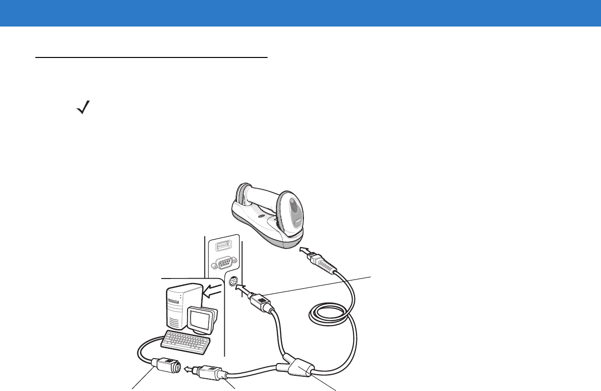
8 - 2 Symbol DS6878 Product Reference Guide
Connecting a Keyboard Wedge Interface
The digital scanner must be connected to the cradle for the host parameter setting to take effect. When the digital
scanner is not connected to a cradle, and a host parameter bar code is scanned, a long low/long high beep
sequence sounds.
Figure 8-1
Keyboard Wedge Connection with Y-cable
To connect the Keyboard Wedge interface Y-cable:
1. Turn off the host and unplug the keyboard connector.
2. Attach the modular connector of the Y-cable to the host port on the bottom of the digital scanner cradle. See
Connecting the Cradle on page 1-6.
3. Connect the round male DIN host connector of the Y-cable to the keyboard port on the host device.
4. Connect the round female DIN keyboard connector of the Y-cable to the keyboard connector.
5. If needed, attach the optional power supply to the connector in the middle of the Y-cable.
6. Ensure that all connections are secure.
7. Turn on the host system.
8. Select the Keyboard Wedge host type by scanning the appropriate bar code from Keyboard Wedge Host
Parameters on page 8-4.
9. To modify any other parameter options, scan the appropriate bar codes in this chapter.
NOTE See Chapter 4, Radio Communications for information about digital scanner/cradle pairing and wireless
communication.
Male DIN
Connector
Female DIN Keyboard
Connector
Keyboard Connector Y-cable
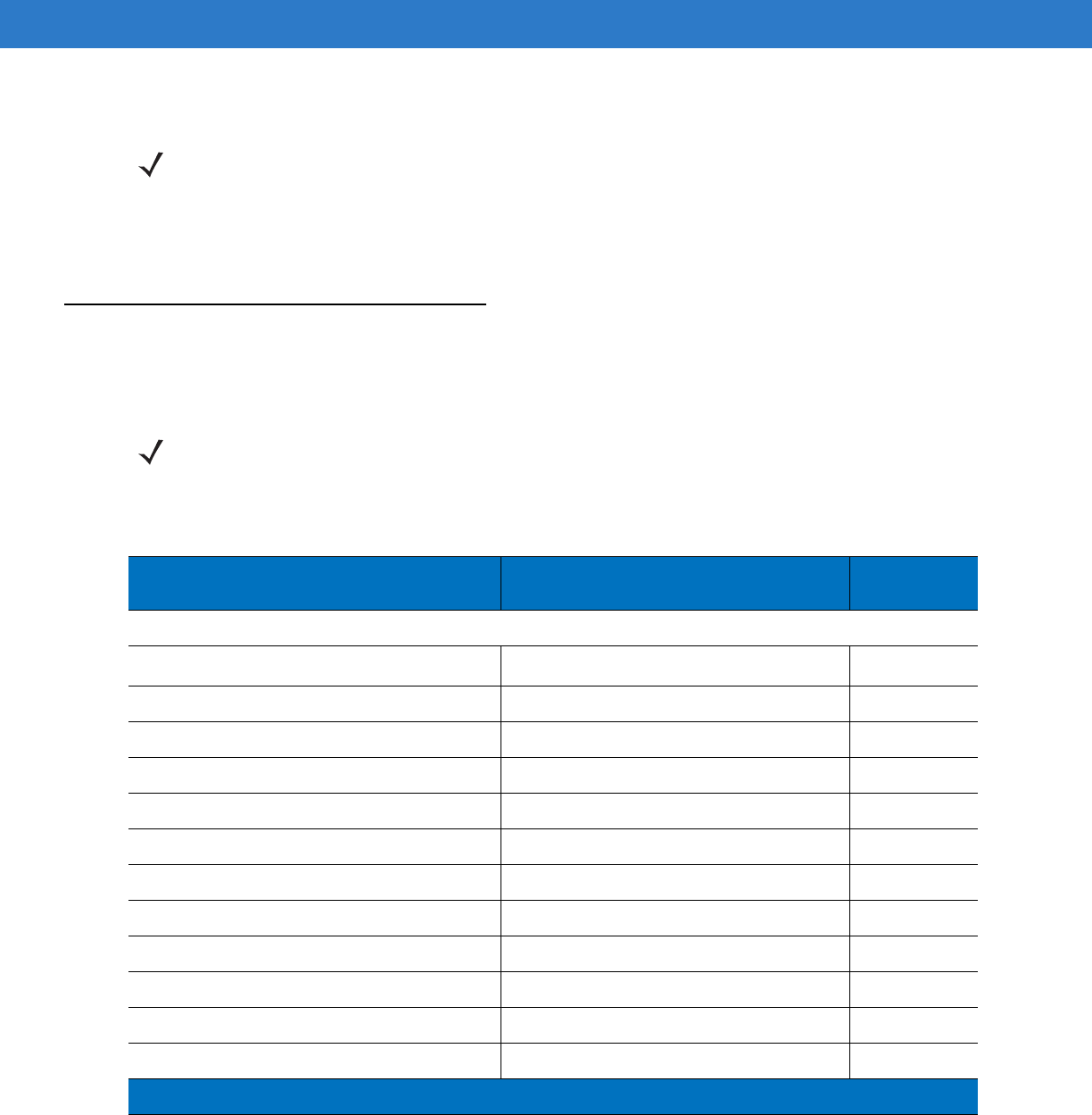
Keyboard Wedge Interface 8 - 3
If a power supply is used, disconnect the power supply before changing host cables or the cradle may not
recognize the new host.
Keyboard Wedge Parameter Defaults
Table 8-1 lists the defaults for Keyboard Wedge host parameters. To change any option, scan the appropriate bar
code(s) in the Keyboard Wedge Host Parameters section beginning on page 8-4.
NOTE Interface cables vary depending on configuration. The connectors illustrated in Figure 8-1 are examples
only. The connectors may be different than those illustrated, but the steps to connect the cradle remain the
same.
NOTE See Appendix A, Standard Default Parameters for all user preferences, hosts, symbologies, and
miscellaneous default parameters.
Table 8-1
Keyboard Wedge Host Default Table
Parameter Default Page
Number
Keyboard Wedge Host Parameters
Keyboard Wedge Host Type IBM PC/AT& IBM PC Compatibles
1
8-4
Country Types (Country Codes) North American
8-5
Ignore Unknown Characters Send
8-6
Keystroke Delay No Delay
8-7
Intra-Keystroke Delay Disable
8-7
Alternate Numeric Keypad Emulation Disable
8-8
Caps Lock On Disable
8-8
Caps Lock Override Disable
8-9
Convert Wedge Data No Convert
8-9
Function Key Mapping Disable
8-10
FN1 Substitution Disable
8-10
Send and Make Break Send
8-11
1
User selection is required to configure this interface and this is the most common selection.
8 - 4 Symbol DS6878 Product Reference Guide
Keyboard Wedge Host Parameters
Keyboard Wedge Host Types
Select the Keyboard Wedge host by scanning one of the bar codes below.
IBM PC/AT & IBM PC Compatibles1
IBM AT Notebook
NOTE 1User selection is required to configure this interface and this is the most common selection.
Keyboard Wedge Interface 8 - 5
Keyboard Wedge Country Types (Country Codes)
Scan the bar code corresponding to the keyboard type. If the keyboard type is not listed, see Alternate Numeric
Keypad Emulation on page 8-8.
*North American
German Windows
French Windows
French Canadian Windows 95/98
French Canadian Windows XP/2000
Spanish Windows
Italian Windows
8 - 6 Symbol DS6878 Product Reference Guide
Ignore Unknown Characters
Unknown characters are characters the host does not recognize. When Send Bar Codes With Unknown
Characters is selected, all bar code data is sent except for unknown characters, and no error beeps sound on the
digital scanner. When Do Not Send Bar Codes With Unknown Characters is selected, bar code data is sent up
to the first unknown character, then the digital scanner issues an error beep.
Keyboard Wedge Country Types (Country Codes continued)
Swedish Windows
UK English Windows
Japanese Windows
Portuguese-Brazilian Windows
*Send Bar Codes with Unknown Characters
Do Not Send Bar Codes with Unknown Characters
Keyboard Wedge Interface 8 - 7
Keystroke Delay
This is the delay in milliseconds between emulated keystrokes. Scan a bar code below to increase the delay when
hosts require a slower transmission of data.
Intra-Keystroke Delay
When enabled, an additional delay is inserted between each emulated key depression and release. This sets the
Keystroke Delay parameter to a minimum of 5 msec as well.
*No Delay
Medium Delay (20 msec)
Long Delay (40 msec)
Enable Intra-Keystroke Delay
*Disable Intra-Keystroke Delay
8 - 8 Symbol DS6878 Product Reference Guide
Alternate Numeric Keypad Emulation
This allows emulation of most other country keyboard types not listed in Keyboard Wedge Country Types (Country
Codes) on page 8-5 in a Microsoft® operating system environment.
Caps Lock On
When enabled, the digital scanner emulates keystrokes as if the Caps Lock key is always pressed. Note that if both
Caps Lock On and Caps Lock Override are enabled, Caps Lock Override takes precedence
Enable Alternate Numeric Keypad
*Disable Alternate Numeric Keypad
Enable Caps Lock On
*Disable Caps Lock On
Keyboard Wedge Interface 8 - 9
Caps Lock Override
When enabled, on AT or AT Notebook hosts, the keyboard ignores the state of the Caps Lock key. Therefore, an ‘A’
in the bar code is sent as an ‘A’ no matter what the state of the keyboard’s Caps Lock key.
Note that if both Caps Lock On and Caps Lock Override are enabled, Caps Lock Override takes precedence.
Convert Wedge Data
When enabled, the digital scanner converts all bar code data to the selected case.
Enable Caps Lock Override
*Disable Caps Lock Override
Convert to Upper Case
Convert to Lower Case
*No Convert
8 - 10 Symbol DS6878 Product Reference Guide
Function Key Mapping
ASCII values under 32 are normally sent as control key sequences (see Table 8-2 on page 8-13). When this
parameter is enabled, the keys in bold are sent in place of the standard key mapping. Table entries that do not
have a bold entry remain the same whether or not this parameter is enabled.
FN1 Substitution
When enabled, the digital scanner replaces FN1 characters in an EAN128 bar code with a keystroke chosen by the
user (see FN1 Substitution Values on page 5-36).
Enable Function Key Mapping
*Disable Function Key Mapping
Enable FN1 Substitution
*Disable FN1 Substitution

Keyboard Wedge Interface 8 - 11
Send Make and Break
When enabled, the scan codes for releasing a key are not sent.
*Send Make and Break Scan Codes
Send Make Scan Code Only
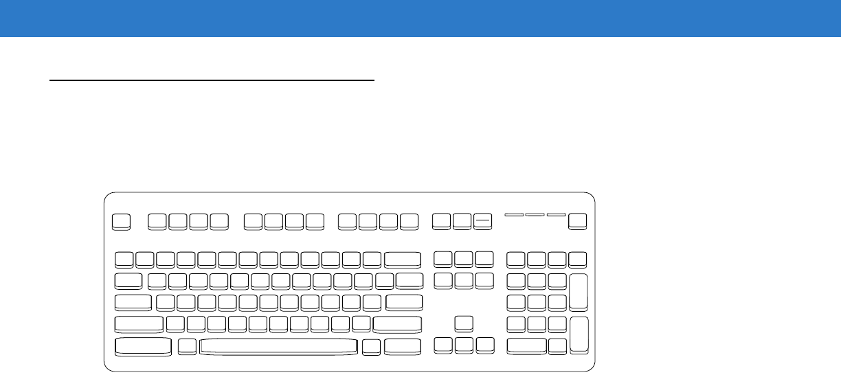
8 - 12 Symbol DS6878 Product Reference Guide
Keyboard Maps
Refer to the following keyboard map for prefix/suffix keystroke parameters. To program the prefix/suffix values, see
the bar codes on page 5-34.
Figure 8-2
IBM PS2 Type Keyboard
7013
7014 5001 5002 5003 5004 5005 5006 5007 5008 5009 5010
7013
5011 7010 7007 7006
7001
5012
7008
7009
7011 7012 7003
7002 7004 7005
7017 7016
7015
7018

Keyboard Wedge Interface 8 - 13
ASCII Character Set for Keyboard Wedge
NOTE Code 39 Full ASCII interprets the bar code special character ($ + % /) preceding a Code 39 character and
assigns an ASCII character value to the pair. For example, when Code 39 Full ASCII is enabled and a +B
is scanned, it is interpreted as b, %J as ?, and %V as @. Scanning ABC%I outputs the keystroke
equivalent of ABC >..
Table 8-2
Keyboard Wedge ASCII Character Set
ASCII Value Full ASCII
Code 39 Encode Character Keystroke
1001 $A CTRL A
1002 $B CTRL B
1003 $C CTRL C
1004 $D CTRL D
1005 $E CTRL E
1006 $F CTRL F
1007 $G CTRL G
1008 $H CTRL H/
BACKSPACE
1
1009 $I CTRL I/
HORIZONTAL TAB
1
1010 $J CTRL J
1011 $K CTRL K
1012 $L CTRL L
1013 $M CTRL M/
ENTER
1
1014 $N CTRL N
1015 $O CTRL O
1016 $P CTRL P
1017 $Q CTRL Q
1018 $R CTRL R
1019 $S CTRL S
1020 $T CTRL T
1021 $U CTRL U
1
The keystroke in bold is sent only if the “Function Key Mapping” is enabled.
Otherwise, the unbolded keystroke is sent.

8 - 14 Symbol DS6878 Product Reference Guide
1022 $V CTRL V
1023 $W CTRL W
1024 $X CTRL X
1025 $Y CTRL Y
1026 $Z CTRL Z
1027 %A CTRL [ /
ESC
1
1028 %B CTRL \
1029 %C CTRL ]
1030 %D CTRL 6
1031 %E CTRL -
1032 Space Space
1033 /A !
1034 /B “
1035 /C #
1036 /D $
1037 /E %
1038 /F &
1039 /G ‘
1040 /H (
1041 /I )
1042 /J *
1043 /K +
1044 /L ,
1045 - -
1046 . .
1047 /O /
1048 0 0
1049 1 1
Table 8-2
Keyboard Wedge ASCII Character Set (Continued)
ASCII Value Full ASCII
Code 39 Encode Character Keystroke
1
The keystroke in bold is sent only if the “Function Key Mapping” is enabled.
Otherwise, the unbolded keystroke is sent.

Keyboard Wedge Interface 8 - 15
1050 2 2
1051 3 3
1052 4 4
1053 5 5
1054 6 6
1055 7 7
1056 8 8
1057 9 9
1058 /Z :
1059 %F ;
1060 %G <
1061 %H =
1062 %I >
1063 %J ?
1064 %V @
1065 A A
1066 B B
1067 C C
1068 D D
1069 E E
1070 F F
1071 G G
1072 H H
1073 I I
1074 J J
1075 K K
1076 L L
1077 M M
Table 8-2
Keyboard Wedge ASCII Character Set (Continued)
ASCII Value Full ASCII
Code 39 Encode Character Keystroke
1
The keystroke in bold is sent only if the “Function Key Mapping” is enabled.
Otherwise, the unbolded keystroke is sent.

8 - 16 Symbol DS6878 Product Reference Guide
1078 N N
1079 O O
1080 P P
1081 Q Q
1082 R R
1083 S S
1084 T T
1085 U U
1086 V V
1087 W W
1088 X X
1089 Y Y
1090 Z Z
1091 %K [
1092 %L \
1093 %M ]
1094 %N ^
1095 %O _
1096 %W ‘
1097 +A a
1098 +B b
1099 +C c
1100 +D d
1101 +E e
1102 +F f
1103 +G g
1104 +H h
1105 +I i
Table 8-2
Keyboard Wedge ASCII Character Set (Continued)
ASCII Value Full ASCII
Code 39 Encode Character Keystroke
1
The keystroke in bold is sent only if the “Function Key Mapping” is enabled.
Otherwise, the unbolded keystroke is sent.
Keyboard Wedge Interface 8 - 17
1106 +J j
1107 +K k
1108 +L l
1109 +M m
1110 +N n
1111 +O o
1112 +P p
1113 +Q q
1114 +R r
1115 +S s
1116 +T t
1117 +U u
1118 +V v
1119 +W w
1120 +X x
1121 +Y y
1122 +Z z
1123 %P {
1124 %Q |
1125 %R }
1126 %S ~
Table 8-3
Keyboard Wedge ALT Key Character Set
ALT Keys Keystroke
2065 ALT A
2066 ALT B
2067 ALT C
2068 ALT D
2069 ALT E
Table 8-2
Keyboard Wedge ASCII Character Set (Continued)
ASCII Value Full ASCII
Code 39 Encode Character Keystroke
1
The keystroke in bold is sent only if the “Function Key Mapping” is enabled.
Otherwise, the unbolded keystroke is sent.

8 - 18 Symbol DS6878 Product Reference Guide
2070 ALT F
2071 ALT G
2072 ALT H
2073 ALT I
2074 ALT J
2075 ALT K
2076 ALT L
2077 ALT M
2078 ALT N
2079 ALT O
2080 ALT P
2081 ALT Q
2082 ALT R
2083 ALT S
2084 ALT T
2085 ALT U
2086 ALT V
2087 ALT W
2088 ALT X
2089 ALT Y
2090 ALT Z
Table 8-4
Keyboard Wedge GIU Key Character Set
GUI Keys Keystrokes
3000 Right Control Key
3048 GUI 0
3049 GUI 1
3050 GUI 2
3051 GUI 3
3052 GUI 4
3053 GUI 5
Table 8-3
Keyboard Wedge ALT Key Character Set (Continued)
ALT Keys Keystroke

Keyboard Wedge Interface 8 - 19
3054 GUI 6
3055 GUI 7
3056 GUI 8
3057 GUI 9
3065 GUI A
3066 GUI B
3067 GUI C
3068 GUI D
3069 GUI E
3070 GUI F
3071 GUI G
3072 GUI H
3073 GUI I
3074 GUI J
3075 GUI K
3076 GUI L
3077 GUI M
3078 GUI N
3079 GUI O
3080 GUI P
3081 GUI Q
3082 GUI R
3083 GUI S
3084 GUI T
3085 GUI U
3086 GUI V
3087 GUI W
3088 GUI X
3089 GUI Y
3090 GUI Z
Table 8-4
Keyboard Wedge GIU Key Character Set (Continued)
GUI Keys Keystrokes

8 - 20 Symbol DS6878 Product Reference Guide
Table 8-5
Keyboard Wedge F Key Character Set
F Keys Keystroke
5001 F1
5002 F2
5003 F3
5004 F4
5005 F5
5006 F6
5007 F7
5008 F8
5009 F9
5010 F10
5011 F11
5012 F12
5013 F13
5014 F14
5015 F15
5016 F16
5017 F17
5018 F18
5019 F19
5020 F20
5021 F21
5022 F22
5023 F23
5024 F24

Keyboard Wedge Interface 8 - 21
Table 8-6
Keyboard Wedge Numeric Keypad Character Set
Numeric Keypad Keystroke
6042 *
6043 +
6044 undefined
6045 -
6046 .
6047 /
6048 0
6049 1
6050 2
6051 3
6052 4
6053 5
6054 6
6055 7
6056 8
6057 9
6058 Enter
6059 Num Lock

8 - 22 Symbol DS6878 Product Reference Guide
Table 8-7
Keyboard Wedge Extended Keypad Character Set
Extended Keypad Keystroke
7001 Break
7002 Delete
7003 Pg Up
7004 End
7005 Pg Dn
7006 Pause
7007 Scroll Lock
7008 Backspace
7009 Tab
7010 Print Screen
7011 Insert
7012 Home
7013 Enter
7014 Escape
7015 Up Arrow
7016 Dn Arrow
7017 Left Arrow
7018 Right Arrow