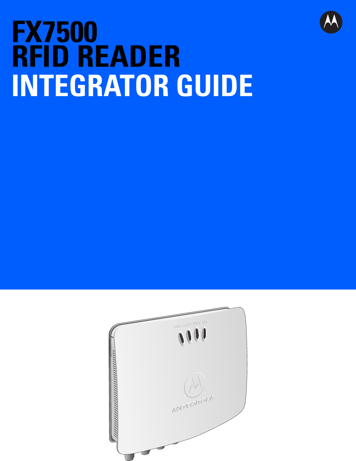
Zebra Technologies FX7500 FX7500 RFID Fixed Reader User Manual Installer Guide part 1
Zebra Technologies Corporation FX7500 RFID Fixed Reader Installer Guide part 1
UserManual.wiki
>
Zebra Technologies
>
FX7500 User Manual
>
Installer Guide part 1
Contents
1.
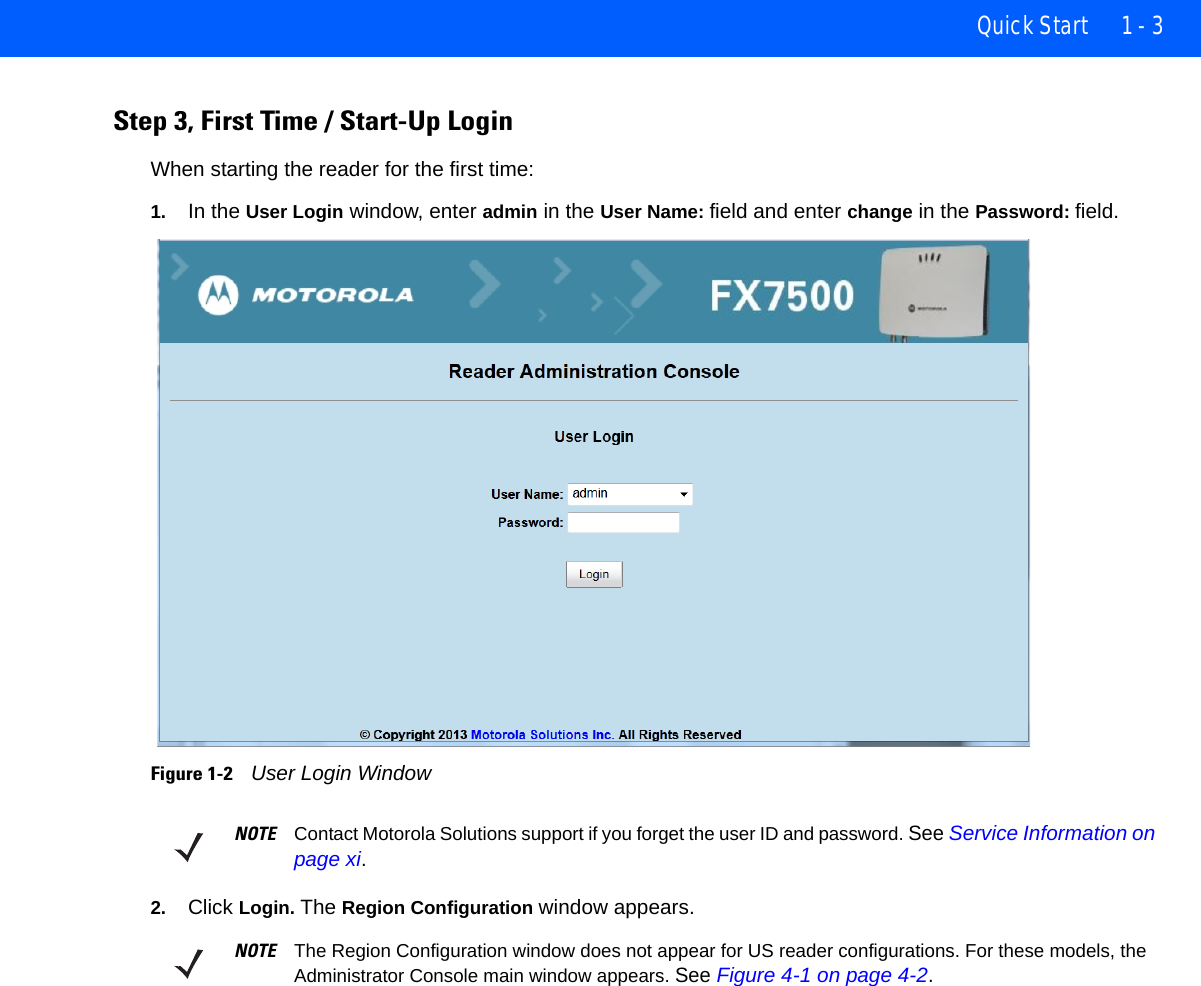
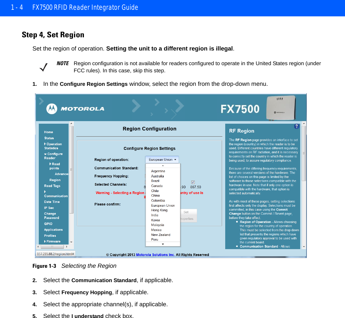
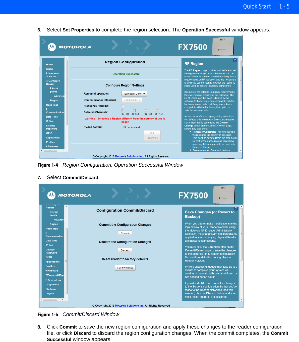
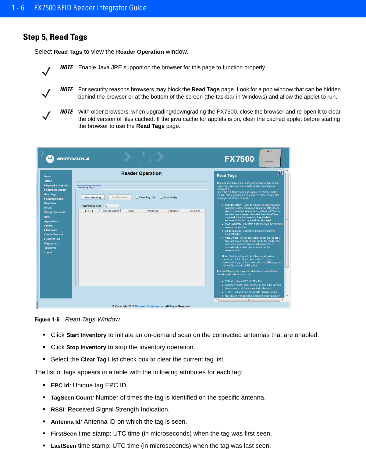
Quick Start Guide
2.
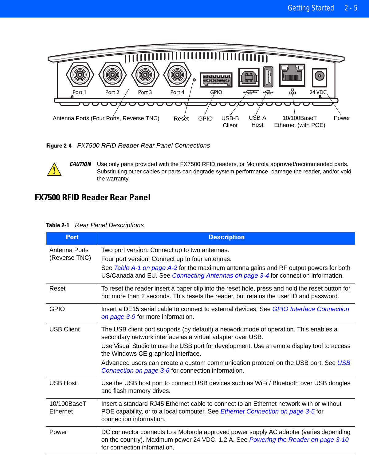
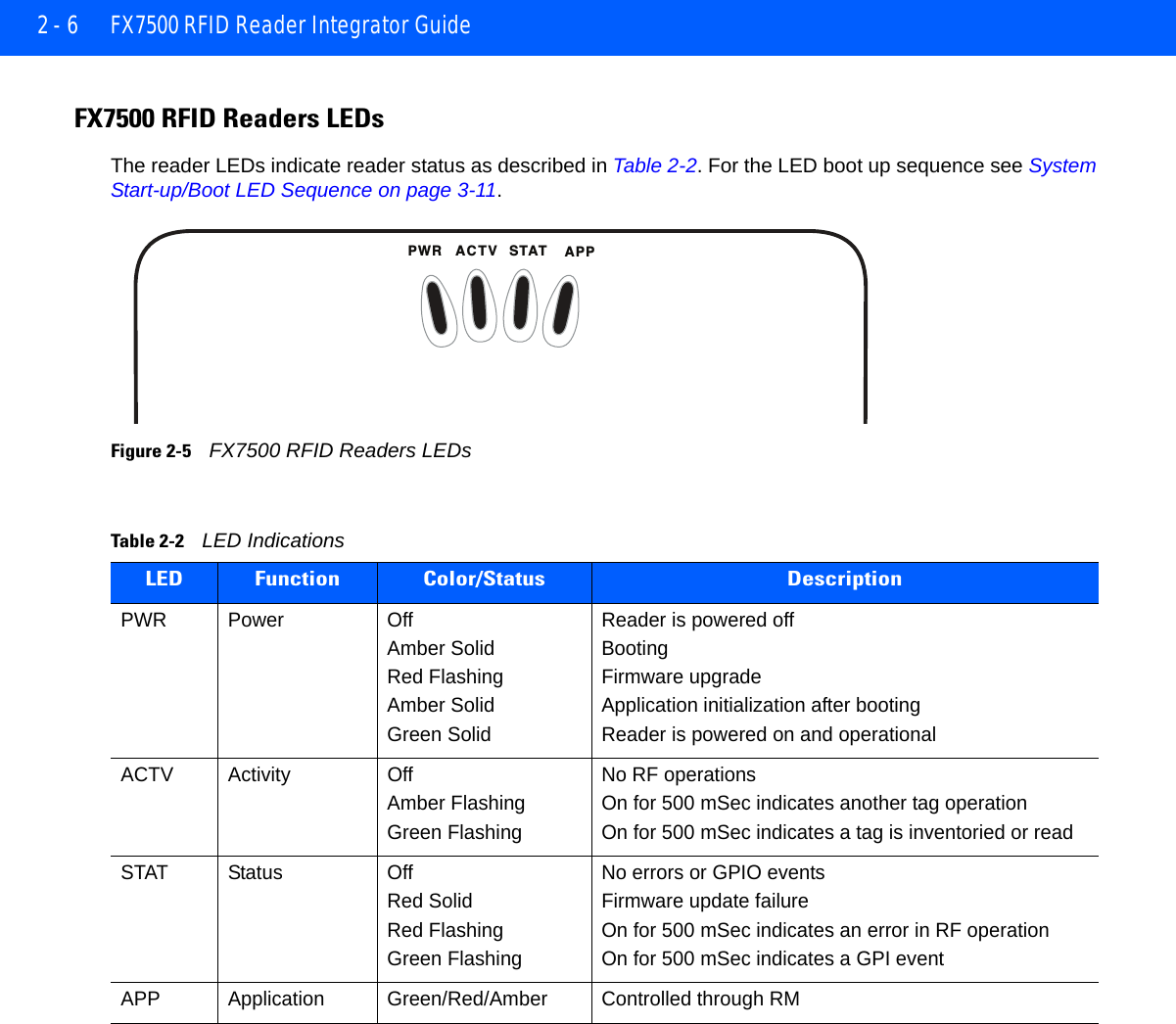
Installer Guide part 1
3.
Installer Guide part 2
4.
Installer Guide part 3
5.
Integrator Guide
6.
User Manual
Installer Guide part 1
Navigation menu
Upload a User Manual
Namespaces
Wiki Guide
HTML
PDF
Info
Views
User Manual
Discussion / Help
Navigation