Zebra Technologies FX7500 FX7500 RFID Fixed Reader User Manual Installer Guide part 2
Zebra Technologies Corporation FX7500 RFID Fixed Reader Installer Guide part 2
UserManual.wiki
>
Zebra Technologies
>
FX7500 User Manual
>
Installer Guide part 2
Contents
1.
Quick Start Guide
2.
Installer Guide part 1
3.
Installer Guide part 2
4.
Installer Guide part 3
5.
Integrator Guide
6.
User Manual
Installer Guide part 2
Navigation menu
Upload a User Manual
Namespaces
Wiki Guide
HTML
PDF
Info
Views
User Manual
Discussion / Help
Navigation
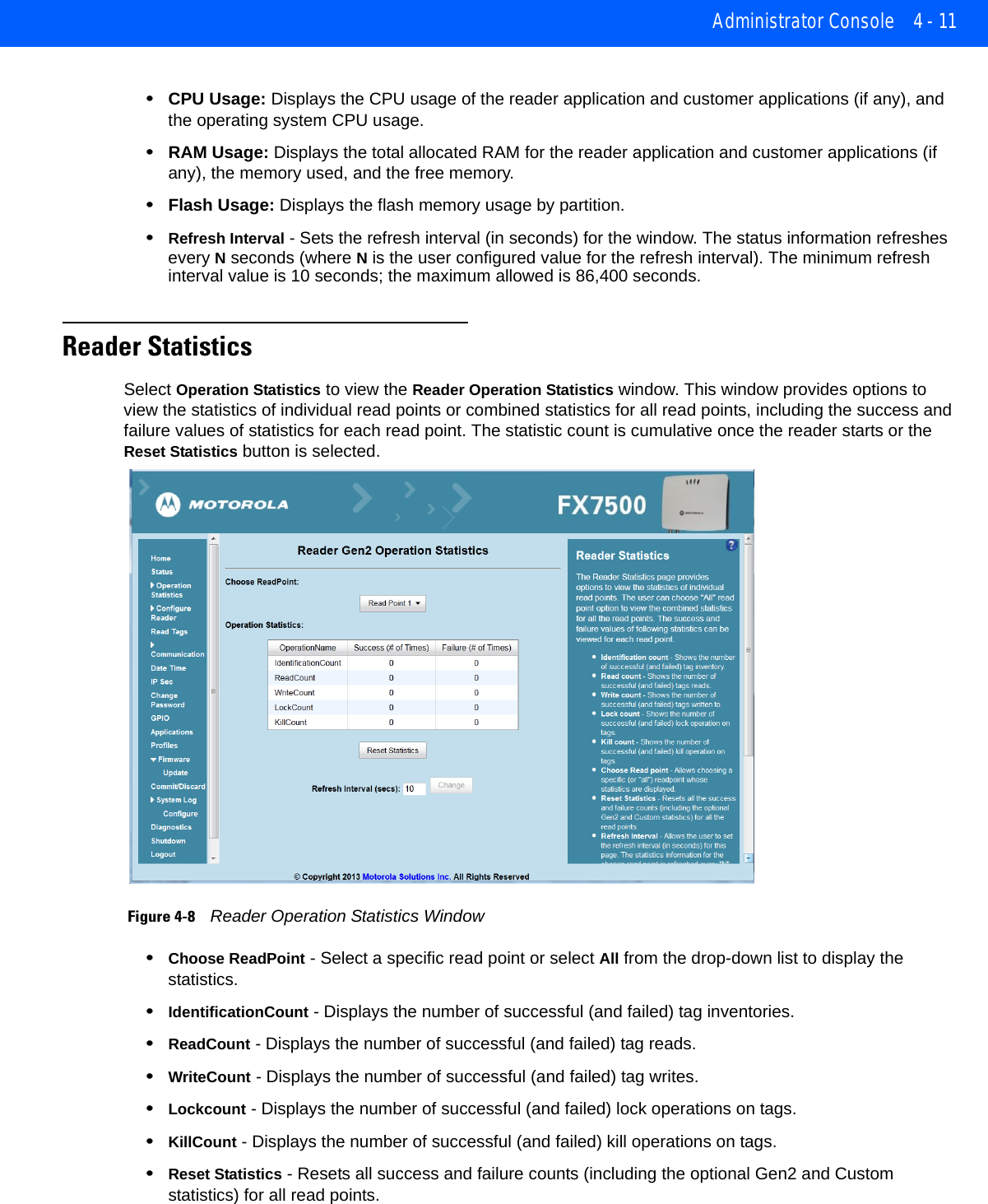
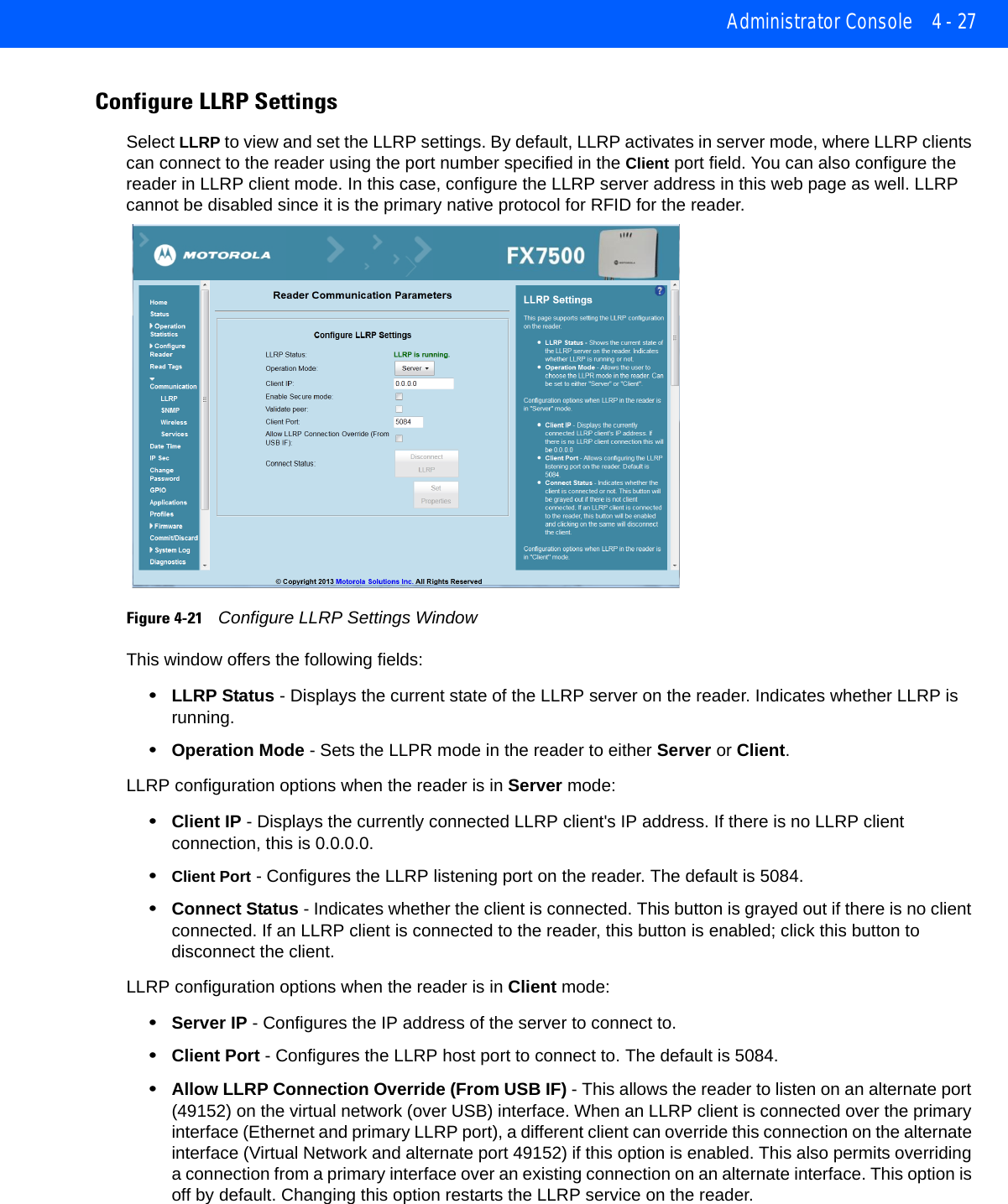
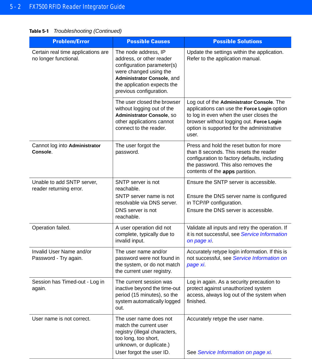
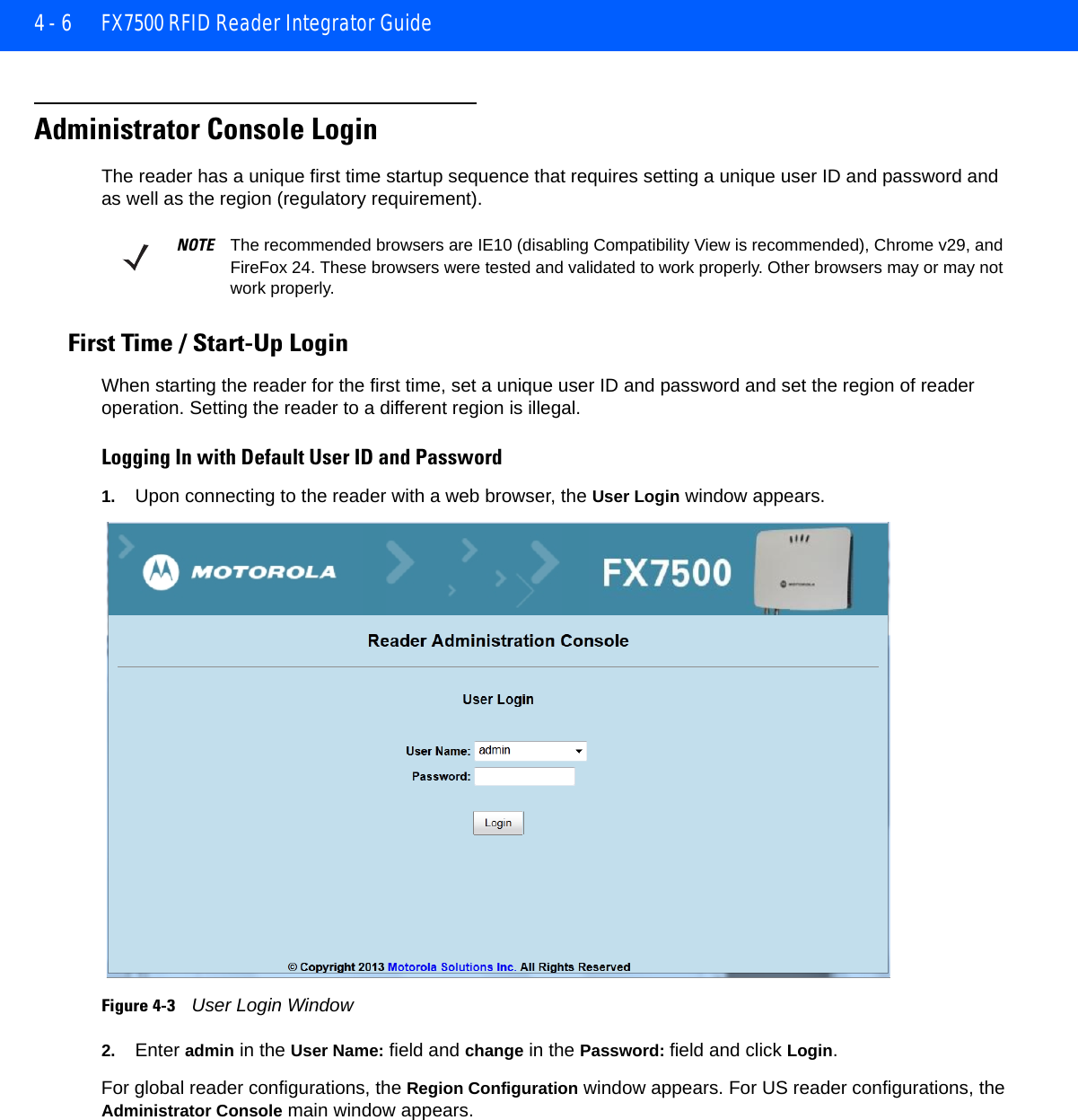
![Administrator Console 4 - 5Using Zero-Configuration Networking when DHCP Server is Not AvailableIf a DHCP server is not available, the FX7500 reader can use zero-configuration networking to automatically provide a unique network IP address. The reader can then use TCP/IP to communicate with other computers also using a zero-configuration networking-generated IP address.The zero-configuration networking procedure is recommended when the reader is connected directly to a PC. It reduces the overhead needed to configure the reader to a static IP address.When zero-configuration networking executes after failing to detect a DHCP server, the reader automatically assigns an IPv4 IP address to the Ethernet interface in the form 169.254.xxx.xxx. This IP address is predictable because it uses the last 2 bytes of the MAC address, usually represented as HEX values, to complete the IPv4 address. These values are converted to decimal format (e.g., if the MAC address ends with 55:9A, the IPv4 address assigned by the zero-configuration algorithm is 169.254.85.148.Windows-based computers support APIPA [or zero-configuration networking???] by default when DHCP fails. To enable APIPA for a Windows PC, visit http://support.microsoft.com/ and search for APIPA.Obtaining the IP Address via Command PromptThe Administrator Console provides the reader IP address. See Figure 4-1 on page 4-2. To obtain the reader IP address without logging into the reader, open a command window and ping the reader host name. See Connecting via Host Name on page 4-3. Figure 4-2 IP Ping WindowNOTE When using zero-configuration networking, the FX7500 reader cannot communicate with computers on different subnets, or that do not use automatic private IP addressing. Automatic private IP addressing is enabled by default.](https://usermanual.wiki/Zebra-Technologies/FX7500.Installer-Guide-part-2/User-Guide-2116837-Page-5.png)
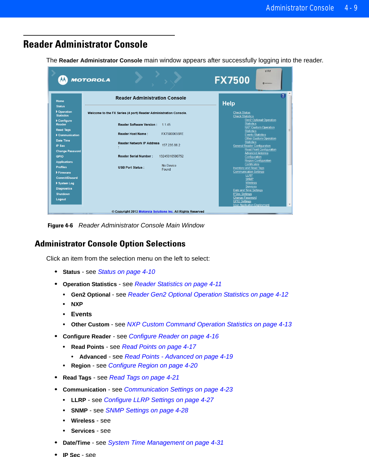
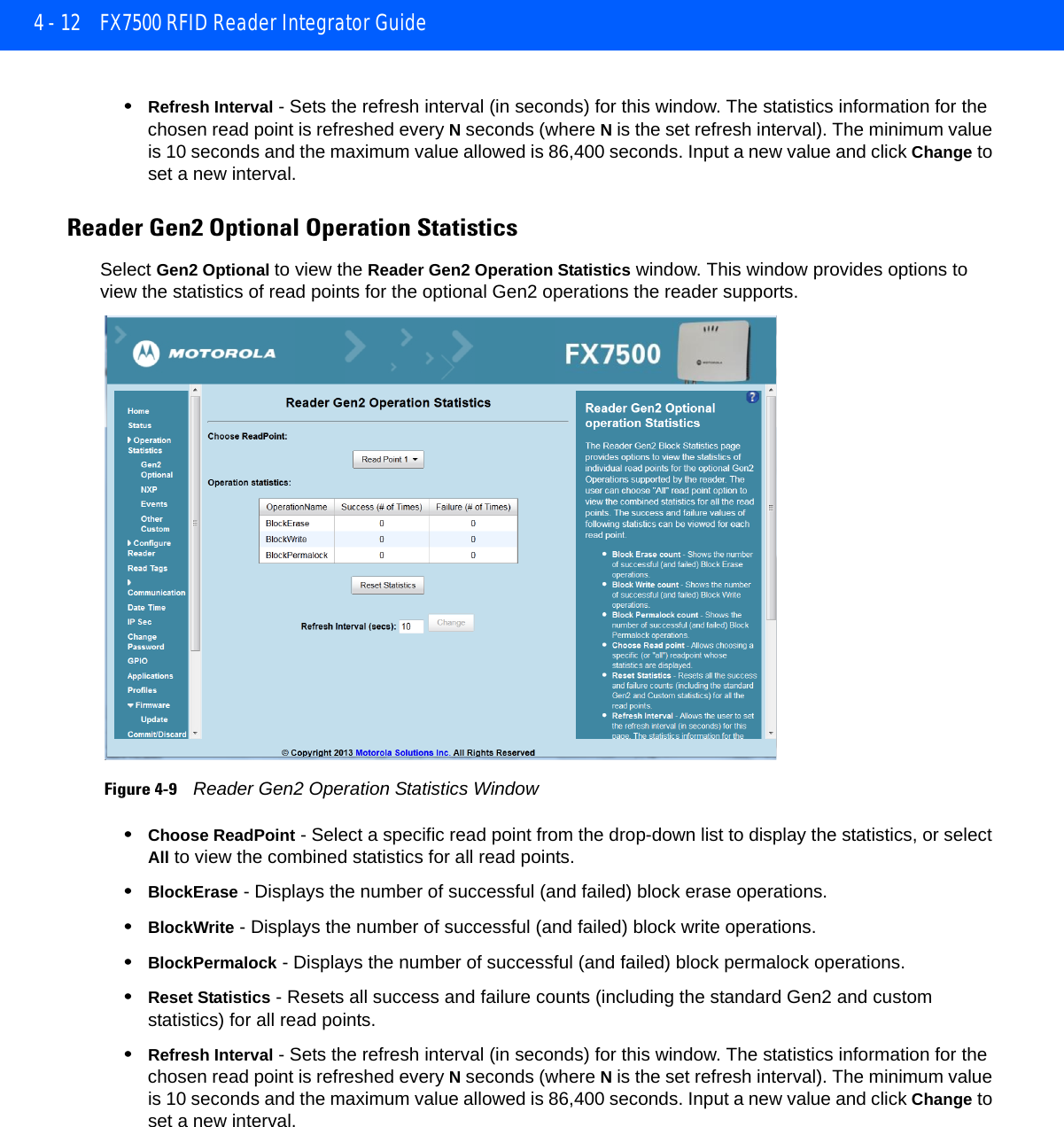
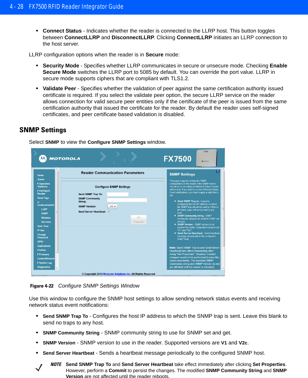
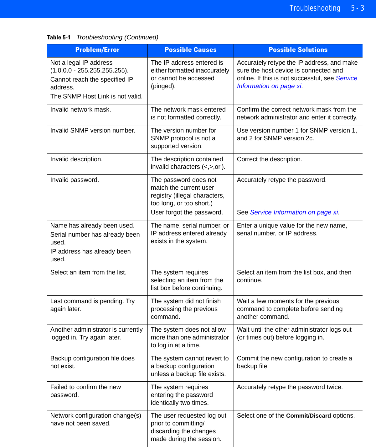
![4 - 10 FX7500 RFID Reader Integrator Guide•Change Password - see •GPIO - see •Applications - see •Profiles - see Reader Profiles on page 4-37•Firmware - see Firmware Version/Update on page 4-39•Update - see Firmware Update on page 4-40•Commit/Discard - see Commit/Discard on page 4-41•System Log - see System Log on page 4-42•Configure - see •Diagnostics - see •Shutdown - see Shutdown on page 4-45•Logout - click Logout to immediately log out of the Administrator Console.StatusClick Status on the selection menu to view the Reader Status window. This window displays information about the reader and read points (antennas). Figure 4-7 Reader Status WindowThe Reader Status window provides consolidated reader status information:•System Clock: The current system clock value, in the format of [Year] [Month] [Day] [Hour: Minute: Second] [Time Difference with UTC]. Click the link to adjust the reader date and time settings.•Up Time - Displays how long the reader has been running, in the format [Number of Days] [Number of Hours] [Number of Minutes] [Number of Seconds].](https://usermanual.wiki/Zebra-Technologies/FX7500.Installer-Guide-part-2/User-Guide-2116837-Page-10.png)