Zebra Technologies FX7500 FX7500 RFID Fixed Reader User Manual Installer Guide part 2
Zebra Technologies Corporation FX7500 RFID Fixed Reader Installer Guide part 2
Contents
Installer Guide part 2

CHAPTER 4 ADMINISTRATOR CONSOLE
Introduction
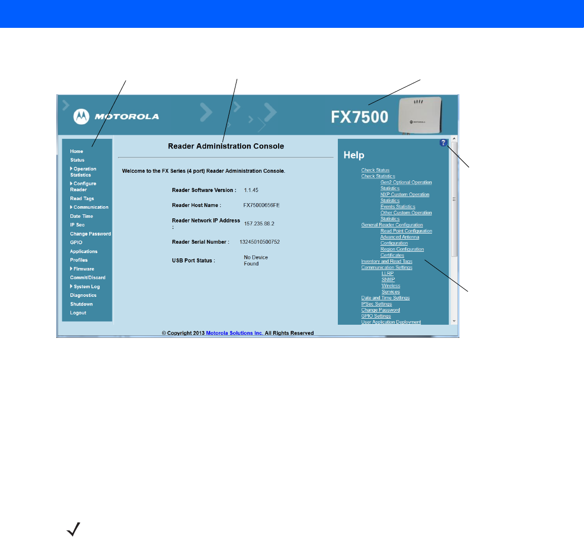
This chapter describes the FX7500 Reader Administrator Console functions and procedures. Access the
Administrator Console using a web browser from a host computer, and use this to manage and configure the
readers. The Administrator Console main window and support windows have four areas, each containing
unique information about the reader.
•
Selection Menu - selects the function for the primary information window.
•
Primary Information Window - provides the primary function information.
•
Product Identification Header - identifies the product.
•
USB Port Status - provides details on the USB device connected to the USB host port. Hover the mouse
pointer over the blue link, available only when a device is detected.
•
Help Information Window:
•provides detailed information to support the primary information window
•includes a scroll bar to scroll through information
•includes a toggle button to turn on/off the help information window
NOTE The screens and windows in this chapter may differ from actual screens and windows. The applications
described may not be available on (or applicable to) all devices. Procedures are not device-specific and
are intended to provide a functional overview.
4 - 2 FX7500 RFID Reader Integrator Guide
Figure 4-1
Reader Administrator Console Main Menu
Profiles
Use profiles for multiple reader deployments to save configuration time, as only a few APIs are needed to
completely configure a reader. See Reader Profiles on page 4-37.
Resetting the Reader
To reset the reader, press and hold the reset button for not more than 2 seconds. See Figure 2-4 on page 2-5
for the reset button location. The reader reboots but retains the user ID and password. See System
Start-up/Boot LED Sequence on page 3-11.
Selection Menu Primary Information Window Product Identification Header
Help Information
Window Toggle
On/Off Button
Help Information
Window
NOTE Hard rebooting the reader (disconnecting power) is not recommended as this discards all the tag events
and system log information.

Administrator Console 4 - 3
Connecting to the Reader
To use the Administrator Console to manage the reader, first power up the reader and connect it to an
accessible network. See Powering the Reader on page 3-10 and Ethernet Connection on page 3-5. The green
power LED indicates that the reader is ready. If the green power LED is not lit, reset the reader. See Resetting
the Reader on page 4-2.
Connect to the reader in one of two ways:
1. Connecting via Host Name on page 4-3
2. Connecting via IP Address on page 4-4
There are three ways to assign an IP address to the reader:
1. Using DHCP on the network
2. Using Zero-Configuration Networking when DHCP Server is Not Available on page 4-5
3. Statically assigning an IP
Any method of assigning the IP supports connection using host name or IP address. Alternatively, connect the
reader directly to a local computer using zero-configuration networking. See Using Zero-Configuration
Networking when DHCP Server is Not Available on page 4-5.
Connecting via Host Name
To connect to the reader using the host name:
1. Open a browser. Recommended browsers are IE10 (disabling Compatibility View is recommended),
Chrome v29, and FireFox 24.
2. Enter the host name provided on the reader label in the browser (e.g., http://fx7500cd3b0d) and press
Enter. The Console Login window appears and the reader is ready.
NOTE This section describes procedures in a Windows environment.
NOTE When using zero-configuration networking, the FX7500 reader cannot communicate with computers on
different subnets, or with computers that do not use automatic private IP addressing.
CAUTION Reader host name is not guaranteed to work at all times. Its recommended use is only in networks
where the probability for IP collisions is low, such as a network in which a DNS server is configured to
work together with DHCP to register host names. Host name usage is not recommended in a network
where there is no strict control to prevent IP collisions, such as informal networks that use IP static
configuration without strict control.

4 - 4 FX7500 RFID Reader Integrator Guide
3. Proceed to Administrator Console Login on page 4-6 to log in to the reader.
Auto Discovery
The FX7500 can automatically belong to a network. The reader implements WS-Discovery conforming to RFID
Reader Management Profile (RDMP) specification in ISO 24791-3. RDMP is based on an extension for Device
Profile for Web Services (DPWS). The discovery mechanism is limited to subnets and does not work across
subnets. The Power Session application supports this feature, and it lists the discovered reader using reader
hostnames. Because this feature is based on WS-Discovery, the readers can also be discovered in Windows
Vista and Windows 7 computers by clicking on the Network icon in a file browser.
Connecting via IP Address
To use the IP address to connect to the reader:
1. Open a browser. Recommended browsers are IE10 (disabling Compatibility View is recommended),
Chrome v29, and FireFox 24.
2. Enter the IP address in the browser (e.g., http://157.235.88.99) and press Enter. The Console Login
window appears and the reader is ready.
3. Proceed to Administrator Console Login on page 4-6 to login to the reader.
NOTE Connect the reader to a network that supports host name registration and lookup to ensure the network
can access the reader using the host name. For instance, some networks can register host names
through DHCP. When first connecting to the reader, it is recommended to keep DHCP enabled in both the
PC and the reader, although it is not guaranteed that the host name will work all the time. Use the host
name printed on the reader label, or construct it using the reader MAC address on the reader back label.
The host name is a string with prefix FX7500, followed by the last three MAC address octets. For
example, for a MAC address of 00:15:70:CD:3B:0D, use the prefix FX7500, followed by the last three
MAC address octets (CD, 3B, and 0D), for the host name FX7500CD3B0D. Type http://FX7500CD3B0D
in the browser address bar to access the reader.
For a network that does not support host name registration and lookup, use the Power Session auto
discovery feature to obtain the IP address, and use the IP address connect method.
Administrator Console 4 - 5
Using Zero-Configuration Networking when DHCP Server is Not Available
If a DHCP server is not available, the FX7500 reader can use zero-configuration networking to automatically
provide a unique network IP address. The reader can then use TCP/IP to communicate with other computers
also using a zero-configuration networking-generated IP address.
The zero-configuration networking procedure is recommended when the reader is connected directly to a PC.
It reduces the overhead needed to configure the reader to a static IP address.
When zero-configuration networking executes after failing to detect a DHCP server, the reader automatically
assigns an IPv4 IP address to the Ethernet interface in the form 169.254.xxx.xxx. This IP address is
predictable because it uses the last 2 bytes of the MAC address, usually represented as HEX values, to
complete the IPv4 address. These values are converted to decimal format (e.g., if the MAC address ends with
55:9A, the IPv4 address assigned by the zero-configuration algorithm is 169.254.85.148.
Windows-based computers support APIPA [or zero-configuration networking???] by default when DHCP fails.
To enable APIPA for a Windows PC, visit http://support.microsoft.com/ and search for APIPA.
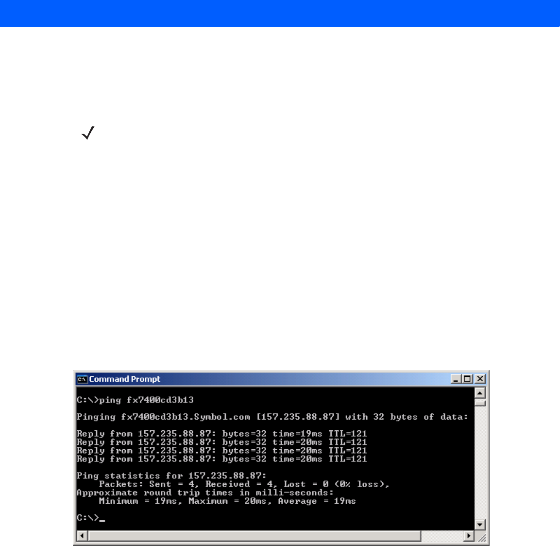
Obtaining the IP Address via Command Prompt
The Administrator Console provides the reader IP address. See Figure 4-1 on page 4-2. To obtain the reader IP
address without logging into the reader, open a command window and ping the reader host name. See
Connecting via Host Name on page 4-3.
Figure 4-2
IP Ping Window
NOTE When using zero-configuration networking, the FX7500 reader cannot communicate with computers on
different subnets, or that do not use automatic private IP addressing. Automatic private IP addressing is
enabled by default.
4 - 6 FX7500 RFID Reader Integrator Guide
Administrator Console Login
The reader has a unique first time startup sequence that requires setting a unique user ID and password and
as well as the region (regulatory requirement).
First Time / Start-Up Login
When starting the reader for the first time, set a unique user ID and password and set the region of reader
operation. Setting the reader to a different region is illegal.
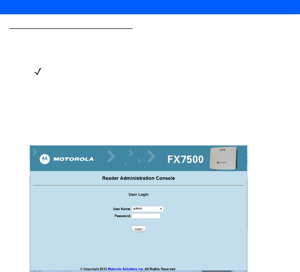
Logging In with Default User ID and Password
1. Upon connecting to the reader with a web browser, the User Login window appears.
Figure 4-3
User Login Window
2. Enter admin in the User Name: field and change in the Password: field and click Login.
For global reader configurations, the Region Configuration window appears. For US reader configurations, the
Administrator Console main window appears.
NOTE The recommended browsers are IE10 (disabling Compatibility View is recommended), Chrome v29, and
FireFox 24. These browsers were tested and validated to work properly. Other browsers may or may not
work properly.
Administrator Console 4 - 7
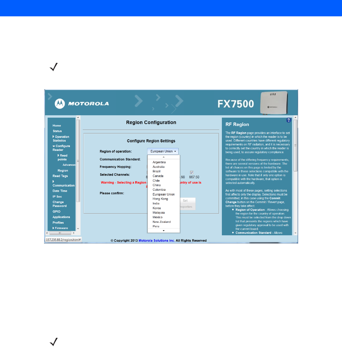
Setting the Region
For global reader configurations, set the region of operation. Setting the unit to a different region is illegal.
1. In the Configure Region Settings window, select the region from the drop-down menu.
Figure 4-4
Selecting the Region
2. Select the Communication Standard if applicable.
3. Select Frequency Hopping, if applicable.
4. Select the appropriate channel(s), if applicable.
5. Click the I understand check box.
6. Click Set Properties to complete the region selection. The Operation Successful window appears.
7. Select Commit/Discard from the selection menu.
NOTE Region configuration is not available for readers configured to operate in the United States region (under
FCC rules). In this case, skip this step.
NOTE Most changes to the reader require a commit to save them.
4 - 8 FX7500 RFID Reader Integrator Guide
Figure 4-5
Commit/Discard Window
8. Click Commit to apply the changes to the reader configuration file, or Discard to discard the new region
configuration changes.
When the commit completes, the Commit Successful window appears. The region is now set and stored in
the reader.
Administrator Console 4 - 9
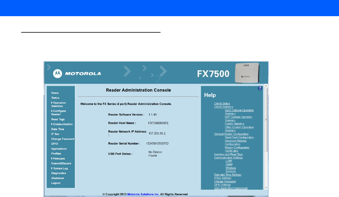
Reader Administrator Console
The Reader Administrator Console main window appears after successfully logging into the reader.
Figure 4-6
Reader Administrator Console Main Window
Administrator Console Option Selections
Click an item from the selection menu on the left to select:
•
Status - see Status on page 4-10
•
Operation Statistics - see Reader Statistics on page 4-11
•Gen2 Optional - see Reader Gen2 Optional Operation Statistics on page 4-12
•NXP
•Events
•Other Custom - see NXP Custom Command Operation Statistics on page 4-13
•
Configure Reader - see Configure Reader on page 4-16
•Read Points - see Read Points on page 4-17
•Advanced - see Read Points - Advanced on page 4-19
•Region - see Configure Region on page 4-20
•
Read Tags - see Read Tags on page 4-21
•
Communication - see Communication Settings on page 4-23
•LLRP - see Configure LLRP Settings on page 4-27
•SNMP - see SNMP Settings on page 4-28
•Wireless - see
•Services - see
•
Date/Time - see System Time Management on page 4-31
•
IP Sec - see
4 - 10 FX7500 RFID Reader Integrator Guide
•
Change Password - see
•
GPIO - see
•
Applications - see
•
Profiles - see Reader Profiles on page 4-37
•
Firmware - see Firmware Version/Update on page 4-39
•Update - see Firmware Update on page 4-40
•
Commit/Discard - see Commit/Discard on page 4-41
•
System Log - see System Log on page 4-42
•Configure - see
•
Diagnostics - see
•
Shutdown - see Shutdown on page 4-45
•
Logout - click Logout to immediately log out of the Administrator Console.
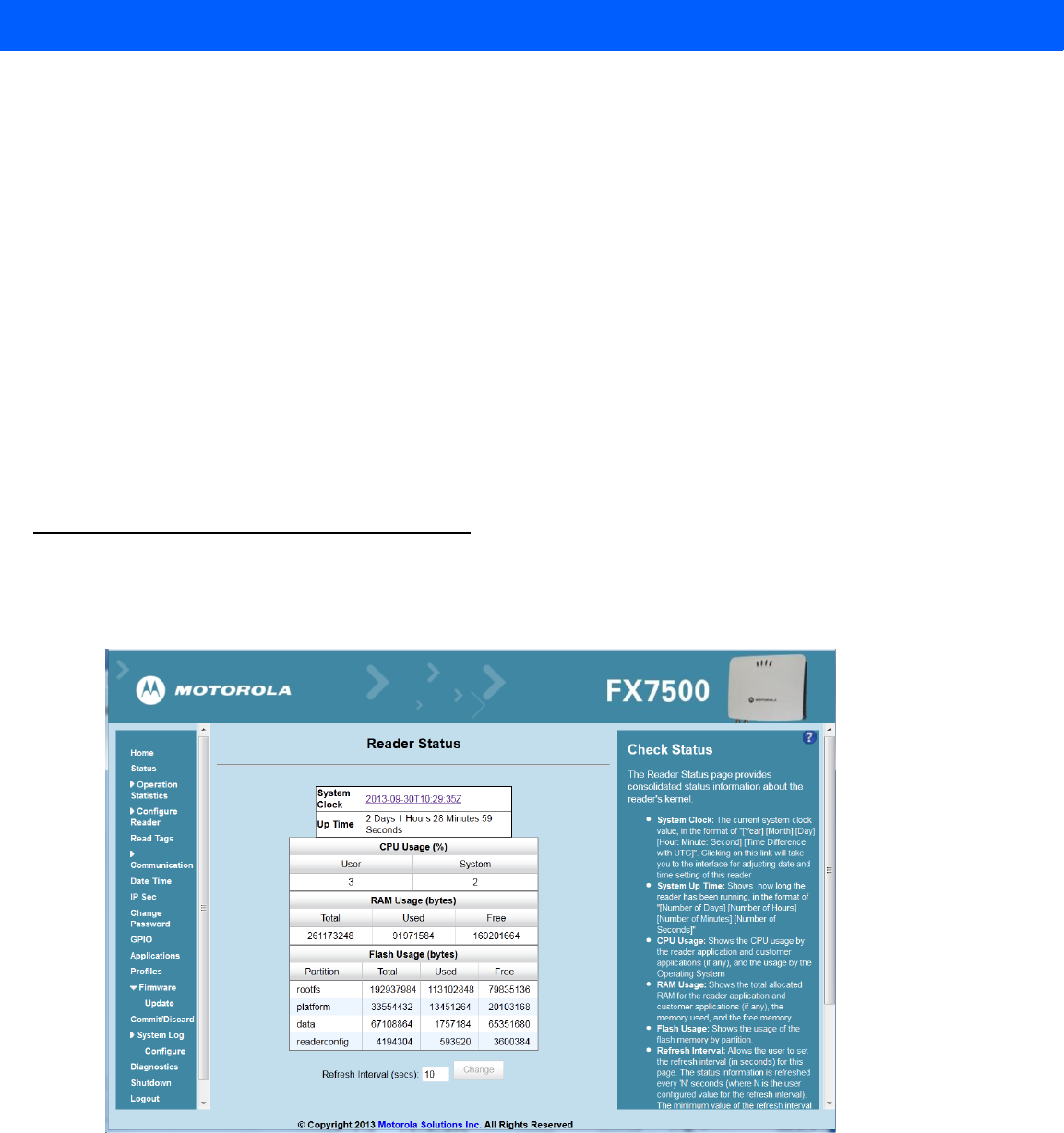
Status
Click Status on the selection menu to view the Reader Status window. This window displays information about
the reader and read points (antennas).
Figure 4-7
Reader Status Window
The Reader Status window provides consolidated reader status information:
•
System Clock: The current system clock value, in the format of [Year] [Month] [Day] [Hour: Minute:
Second] [Time Difference with UTC]. Click the link to adjust the reader date and time settings.
•
Up Time - Displays how long the reader has been running, in the format [Number of Days] [Number of
Hours] [Number of Minutes] [Number of Seconds].
Administrator Console 4 - 11
•
CPU Usage: Displays the CPU usage of the reader application and customer applications (if any), and
the operating system CPU usage.
•
RAM Usage: Displays the total allocated RAM for the reader application and customer applications (if
any), the memory used, and the free memory.
•
Flash Usage: Displays the flash memory usage by partition.
•
Refresh Interval - Sets the refresh interval (in seconds) for the window. The status information refreshes
every N seconds (where N is the user configured value for the refresh interval). The minimum refresh
interval value is 10 seconds; the maximum allowed is 86,400 seconds.
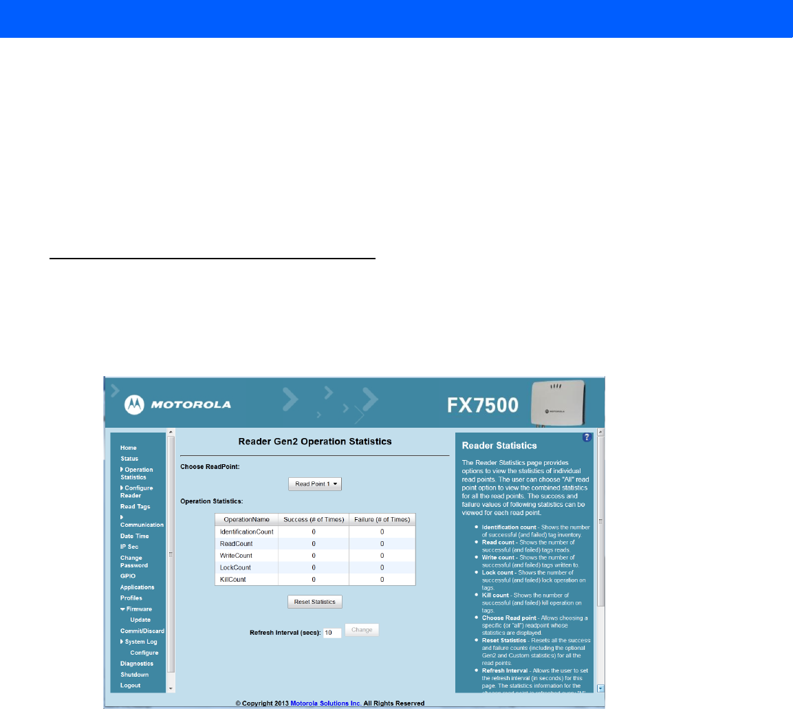
Reader Statistics
Select Operation Statistics to view the Reader Operation Statistics window. This window provides options to
view the statistics of individual read points or combined statistics for all read points, including the success and
failure values of statistics for each read point. The statistic count is cumulative once the reader starts or the
Reset Statistics button is selected.
Figure 4-8
Reader Operation Statistics Window
•
Choose ReadPoint - Select a specific read point or select All from the drop-down list to display the
statistics.
•
IdentificationCount - Displays the number of successful (and failed) tag inventories.
•
ReadCount - Displays the number of successful (and failed) tag reads.
•
WriteCount - Displays the number of successful (and failed) tag writes.
•
Lockcount - Displays the number of successful (and failed) lock operations on tags.
•
KillCount - Displays the number of successful (and failed) kill operations on tags.
•
Reset Statistics - Resets all success and failure counts (including the optional Gen2 and Custom
statistics) for all read points.
4 - 12 FX7500 RFID Reader Integrator Guide
•
Refresh Interval - Sets the refresh interval (in seconds) for this window. The statistics information for the
chosen read point is refreshed every N seconds (where N is the set refresh interval). The minimum value
is 10 seconds and the maximum value allowed is 86,400 seconds. Input a new value and click Change to
set a new interval.
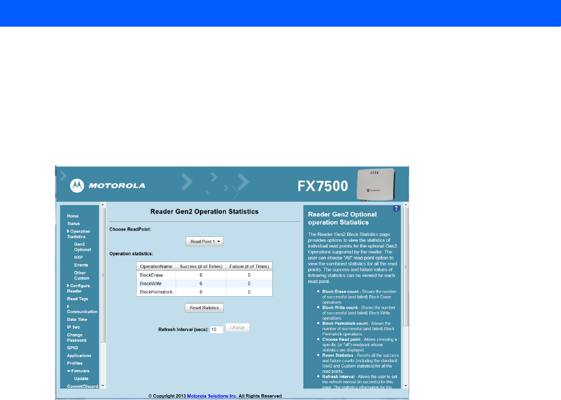
Reader Gen2 Optional Operation Statistics
Select Gen2 Optional to view the Reader Gen2 Operation Statistics window. This window provides options to
view the statistics of read points for the optional Gen2 operations the reader supports.
Figure 4-9
Reader Gen2 Operation Statistics Window
•
Choose ReadPoint - Select a specific read point from the drop-down list to display the statistics, or select
All to view the combined statistics for all read points.
•
BlockErase - Displays the number of successful (and failed) block erase operations.
•
BlockWrite - Displays the number of successful (and failed) block write operations.
•
BlockPermalock - Displays the number of successful (and failed) block permalock operations.
•
Reset Statistics - Resets all success and failure counts (including the standard Gen2 and custom
statistics) for all read points.
•
Refresh Interval - Sets the refresh interval (in seconds) for this window. The statistics information for the
chosen read point is refreshed every N seconds (where N is the set refresh interval). The minimum value
is 10 seconds and the maximum value allowed is 86,400 seconds. Input a new value and click Change to
set a new interval.
Administrator Console 4 - 13
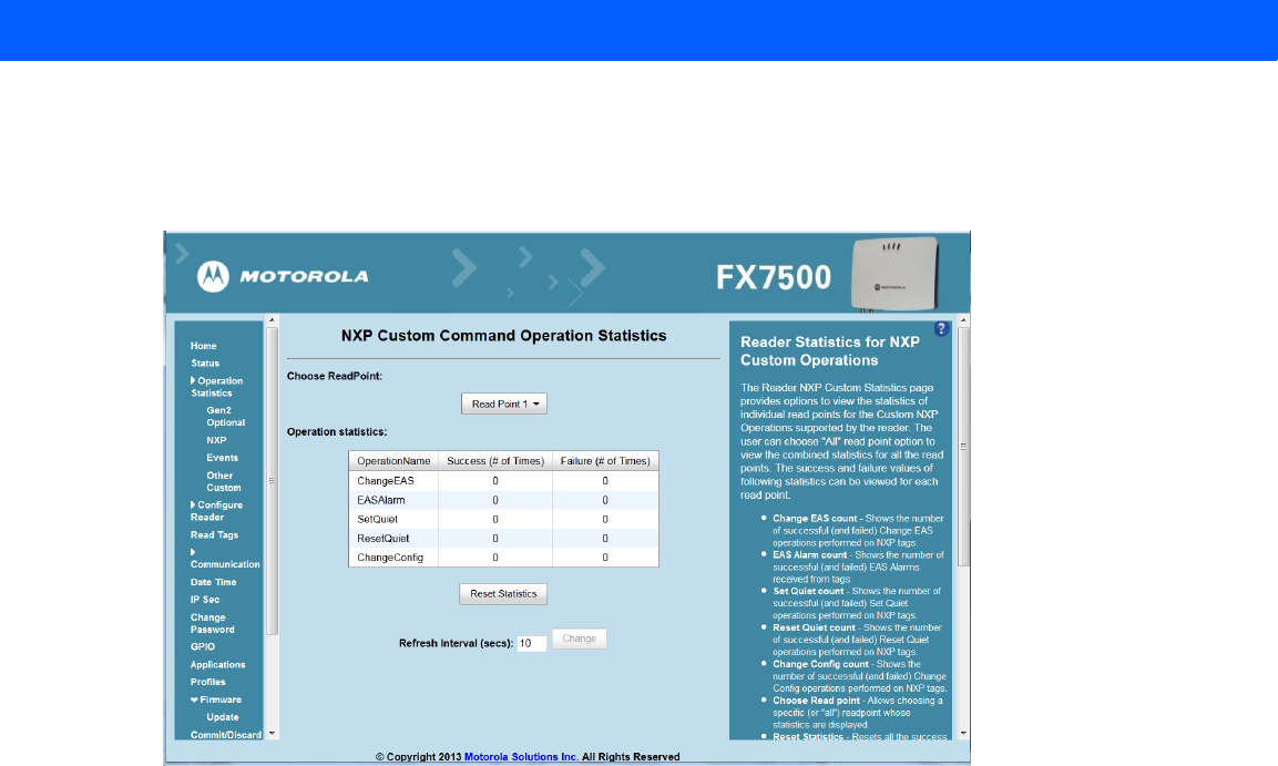
NXP Custom Command Operation Statistics
Select NXP to view the NXP Custom Command Operation Statistics window. This window provides options to
view the statistics of read points for the custom NXP operations the reader supports.
Figure 4-10
NXP Custom Command Operation Statistics Window
•
Choose ReadPoint - Select a specific read point from the drop-down list to display the statistics, or select
All to view the combined statistics for all read points.
•
ChangeEAS - Displays the number of successful (and failed) change EAS operations performed on NXP
tags.
•
EASAlarm - Displays the number of successful (and failed) EAS alarms received from tags.
•
SetQuiet - Displays the number of successful (and failed) set quiet operations performed on NXP tags.
•
ResetQuiet - Displays the number of successful (and failed) reset quiet operations performed on NXP
tags.
•
ChangeConfig - Displays the number of successful (and failed) change configuration operations
performed on NXP tags.
•
Reset Statistics - Resets all the success and failure counts (including the standard and optional Gen2
operation statistics) for all the read points.
•
Refresh Interval - Sets the refresh interval (in seconds) for this window. The statistics information for the
chosen read point is refreshed every N seconds (where N is the set refresh interval). The minimum value
is 10 seconds and the maximum value allowed is 86,400 seconds. Input a new value and click Change to
set a new interval.
4 - 14 FX7500 RFID Reader Integrator Guide
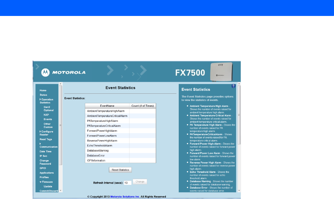
Event Statistics
Select Events to view the Events Statistics window. This window provides options to view the statistics of
events.
Figure 4-11
Event Statistics Window
•
AmbientTemperatureHighAlarm - Displays the number of events raised for ambient temperature high
alarm.
•
AmbientTemperatureCriticalAlarm - Displays the number of events raised for ambient temperature
critical alarm.
•
PATemperatureHighAlarm - Displays the number of events raised for PA temperature high alarm.
•
PATemperatureCriticalAlarm - Displays the number of events raised for PA temperature critical alarm.
•
ForwardPowerHighAlarm - Displays the number of events raised for forward power high alarm.
•
ForwardPowerLowAlarm - Displays the number of events raised for forward power low alarm.
•
ReversePowerHighAlarm - Displays the number of events raised for reverse power high alarm.
•
EchoThresholdAlarm - Displays the number of events raised for echo threshold alarm.
•
DatabaseWarning - Displays the number of events raised for database warning.
•
DatabaseError - Shows the number of events raised for database error.
•
GPIInformation - Shows the number of events raised for GPI events.
•
Reset Statistics - Resets all the success and failure counts for all the read points.
•
Refresh Interval - Sets the refresh interval (in seconds) for this window. The statistics information for the
chosen read point is refreshed every N seconds (where N is the set refresh interval). The minimum value
is 10 seconds and the maximum value allowed is 86,400 seconds. Input a new value and click Change to
set a new interval.
Administrator Console 4 - 15
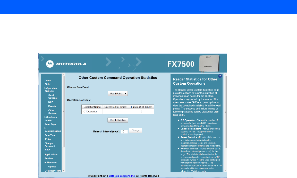
Other Custom Command Operation Statistics
Select Other Custom to view the Other Custom Command Operation Statistics window. This window provides
options to view the statistics of read points for the custom operations the reader supports.
Figure 4-12
NXP Custom Command Operation Statistics Window
•
Choose ReadPoint - Select a specific read point from the drop-down list to display the statistics, or select
All to view the combined statistics for all read points.
•
QTOperation - Displays the number of successful (and failed) QT operations performed on Monza4 QT
tags.
•
Reset Statistics - Resets all the success and failure counts for all the read points.
•
Refresh Interval - Sets the refresh interval (in seconds) for this window. The statistics information for the
chosen read point is refreshed every N seconds (where N is the set refresh interval). The minimum value
is 10 seconds and the maximum value allowed is 86,400 seconds. Input a new value and click Change to
set a new interval.
4 - 16 FX7500 RFID Reader Integrator Guide
Configure Reader
Use the Configure Reader submenus to access the following functions.
Reader Parameters (General)
Select Configure Reader in the selection menu to configure reader settings using this window.
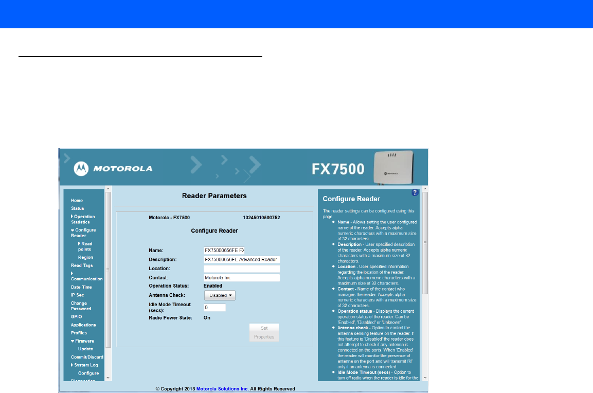
Figure 4-13
Reader Parameters
•
Name - Sets the user-configured reader name. Accepts up to 32 alphanumeric characters.
•
Description - Sets a user-configured reader description. Accepts up to 32 alphanumeric characters.
•
Location - Enter information on the reader location. Accepts up to 32 alphanumeric characters.
•
Contact - Enter the name of the reader manager contact. Accepts up to 32 alphanumeric characters.
•
GPI Debounce Time - Delays input events up to this time, and delivers these events only if the PIN states
remains on the same level.
•
Operation Status - Displays the current operation status of the reader (Enabled, Disabled, or Unknown).
•
Antenna Check - Controls the antenna sensing feature on the reader. Disabled indicates that the reader
does not attempt to check if an antenna is connected on the ports. When Enabled, the reader monitors
the presence of an antenna on the port and only transmits RF if an antenna is connected.
•
Idle Mode Timeout (secs) - Turns off the radio when the reader is idle for the specified time interval. A
value of 0 disables this feature. Enabling this also turns off the antenna check feature when idle mode is
entered after time out.
•
Radio Power State - Displays the current state (On or Off) of the radio. The radio can be turned off if the
Idle Mode Timeout is set to a non-zero value and the radio is not performing RF operations for a time
period greater than the time specified by this timeout. The radio turns on automatically when RF
operation starts.
•
Set Properties - Click to send the changes to the reader.
These settings only affect the display. Use Commit/Discard on page 4-41 to save the changes.
Administrator Console 4 - 17
Read Points
Click Read points in the selection menu to configure the read point settings and view the current read points
state.
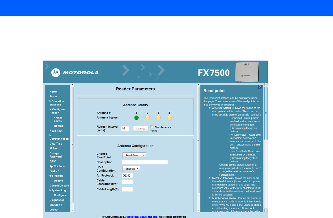
Figure 4-14
Configure Read Points
Antenna Status
•
Status buttons - indicate the status of the reader read points:
•Green: Connected - Read point is enabled and an antenna is connected to the port.
•Red: Not connected - Read point is enabled, but no antenna is connected to the port.
•Yellow: User disabled - The user disabled the read point.
Click a read point’s status button to view and/or change the selected antenna configuration.
•
Refresh Interval - Sets the refresh interval (in seconds) to update the readpoint status. The minimum
value is 10 seconds and the maximum value allowed is 86,400 seconds. Input a new value and click
Change to set a new interval.
•
Maintenance mode - Places the reader in maintenance mode which intermittently drives PWR, ACT,
and STAT LEDs to easily locate the reader. Also enables quick reporting of antenna status by setting the
refresh interval to 2 seconds. Note that you can not modify the refresh interval in this mode.

4 - 18 FX7500 RFID Reader Integrator Guide
Antenna Configuration
•
Choose Read Point - Select a read point to display the configuration.
•
Description - Enter a read point description of up to 32 alphanumeric characters.
•
User Configuration - Enable or disable the read point. Disabling a read point blocks RF operation using
the port/antenna.
•
Air Protocol - Displays the air protocols the read point supports. The reader currently supports only EPC
Class1 GEN2 air protocol.
•
Cable loss (dB/100 ft) - Specifies the cable loss in terms of dB per 100 feet length for the antenna cable
that is used to connect this read point port to the antenna. Refer to the specification of the antenna cable
for this information. The default value is 0. Setting this and the cable length to non-zero values allows the
compensating for the RF signal loss in the cable due to attenuation by specifying an appropriate increase
in the transmit power for this read point. The reader uses this and the cable length value to internally
calculate the cable loss. The calculated cable loss is internally added to the power level configured on
the read point.
•
Cable length (ft) - Sets the cable length in feet of the physical cable that connects the read point port to
the antenna.
•
Set Properties - Select Set Properties to apply the changes. Select Commit/Discard on page 4-41 to save
the changes to the reader.
Administrator Console 4 - 19
Read Points - Advanced
Click Advanced under Read points in the selection menu to view the Advanced Antenna Configuration window.
Use this window to modify the transmission power and frequency configuration elements of the antenna.
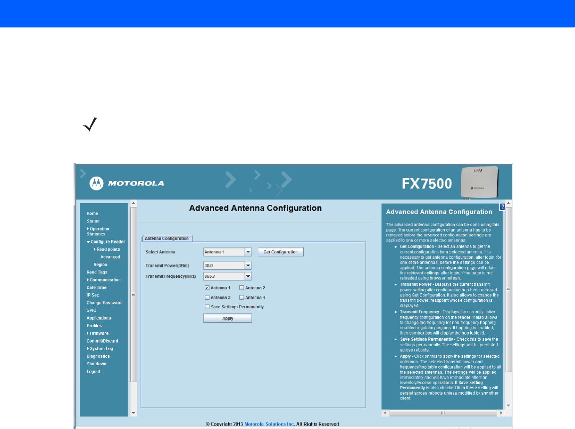
Figure 4-15
Advanced Antenna Configuration
Retrieve the current configuration of an antenna before applying the advanced configuration settings.
•
Get Configuration - Select an antenna to get the current configuration for that antenna. After login, you
must get the antenna configuration for an antenna before settings can be applied. The antenna
configuration page retains the retrieved settings after login if you do not refresh the page using browser
refresh.
•
Transmit Power - Displays the current transmit power setting after selecting Get Configuration, and
allows changing the transmit power for that antenna. This transmit power level does not include cable
loss compensation.
•
Transmit Frequency - Displays the active frequency configuration on the reader, and allows changing
the frequency for non-frequency hopping enabled regulatory regions. If hopping is enabled, the combo
box displays the hop table ID.
•
Save Settings Permanently - Check this to save the settings permanently and persist them across
reboots.
•
Apply - Click to apply the settings for the selected antennas. This applies the selected transmit power
and frequency/hop table configuration to all selected antennas. The settings are applied immediately and
have immediate effect on Inventory/Access operations. Also check Save Setting Permanently to persist
these settings across reboots unless modified by another client.
NOTE This page is not supported when LLRP is configured in secure mode.
4 - 20 FX7500 RFID Reader Integrator Guide
Configure Region
Different countries have different RF regulatory requirements. To assure regulatory compliance, select Region
to set the reader for specific regulatory requirements in the country of reader operation using the Configure
Region Settings window.
Because of the differing frequency requirements, there are several versions of the hardware. The list of
choices on this page is limited by the software to those selections compatible with the hardware in use. Note
that if only one option is compatible with the hardware, that option is selected automatically.
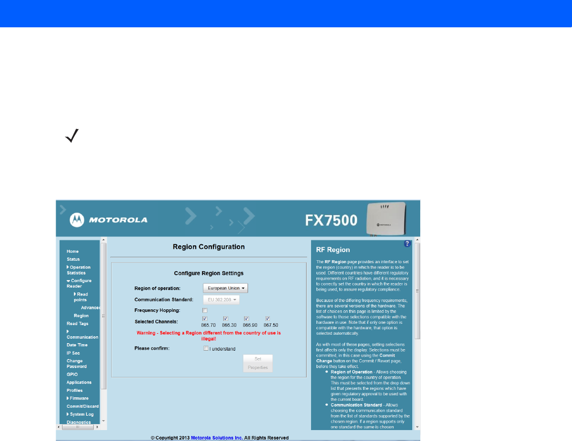
Figure 4-16
Configure Region Settings Window
•
Region of Operation - Select the region for the country of operation from the drop-down list. This list
includes regions which have regulatory approval to use with the current board.
•
Communication Standard - Select the communication standard from the list of standards that the chosen
region supports. If a region supports only one standard, it is automatically selected.
•
Frequency Hopping - Check to select frequency hopping. This option appears only if the chosen region of
operation supports this.
•
Selected Channels - Select a subset of channels on which to operate (from the list of supported
channels). This option appears only if the chosen region of operation supports this.
•
Please confirm - Check the I understand check box to confirm your understanding that the choices are in
compliance with local regulatory requirements.
•
Set Properties - Click to apply the changes. Select Commit/Discard on page 4-41 to save the changes to
the reader.
NOTE Region configuration is not required for readers configured to operate in the United States region (under
FCC rules).
Administrator Console 4 - 21
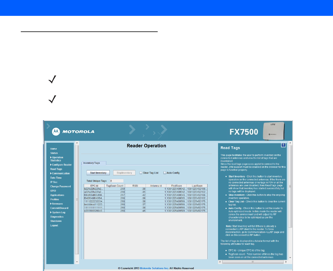
Read Tags
Select Read Tags to view the Reader Operation window. Use this window to perform inventory on the connected
antennas and view the list of inventoried tags.
Figure 4-17
Read Tags Window
•
Start Inventory - Click to starts inventory operation on the connected antennas. If the there are no
connected antennas, no tags in the field of view, or all the antennas are user-disabled, the Read Tags
window indicates that inventory successfully started but no tags display.
•
Stop Inventory - Stops the ongoing inventory operation.
•
Clear Tag List - Clears the current tag list.
•
Auto Config - Check this to set the reader to auto-optimized mode. In this mode the reader senses the
environment and adjusts its RF characteristics to be optimized as per the environment.
•
Total Unique Tags - Indicates the number of unique tags read.
NOTE Enable Java JRE support on the browser in order for this window to function properly.
NOTE This page is not supported when LLRP is configured in secure mode.

4 - 22 FX7500 RFID Reader Integrator Guide
The list of tags appears in a table with the following attributes for each tag:
•
EPC Id - Unique tag EPC ID.
•
TagSeen Count - Number of times the tag was identified on the specific antenna.
•
RSSI - Received Signal Strength Indication.
•
Antenna Id - Antenna ID on which the tag is seen.
•
FirstSeen time stamp - UTC time (in microseconds) when the tag was first seen.
•
LastSeen time stamp - UTC time (in microseconds) when the tag was last seen.
Administrator Console 4 - 23
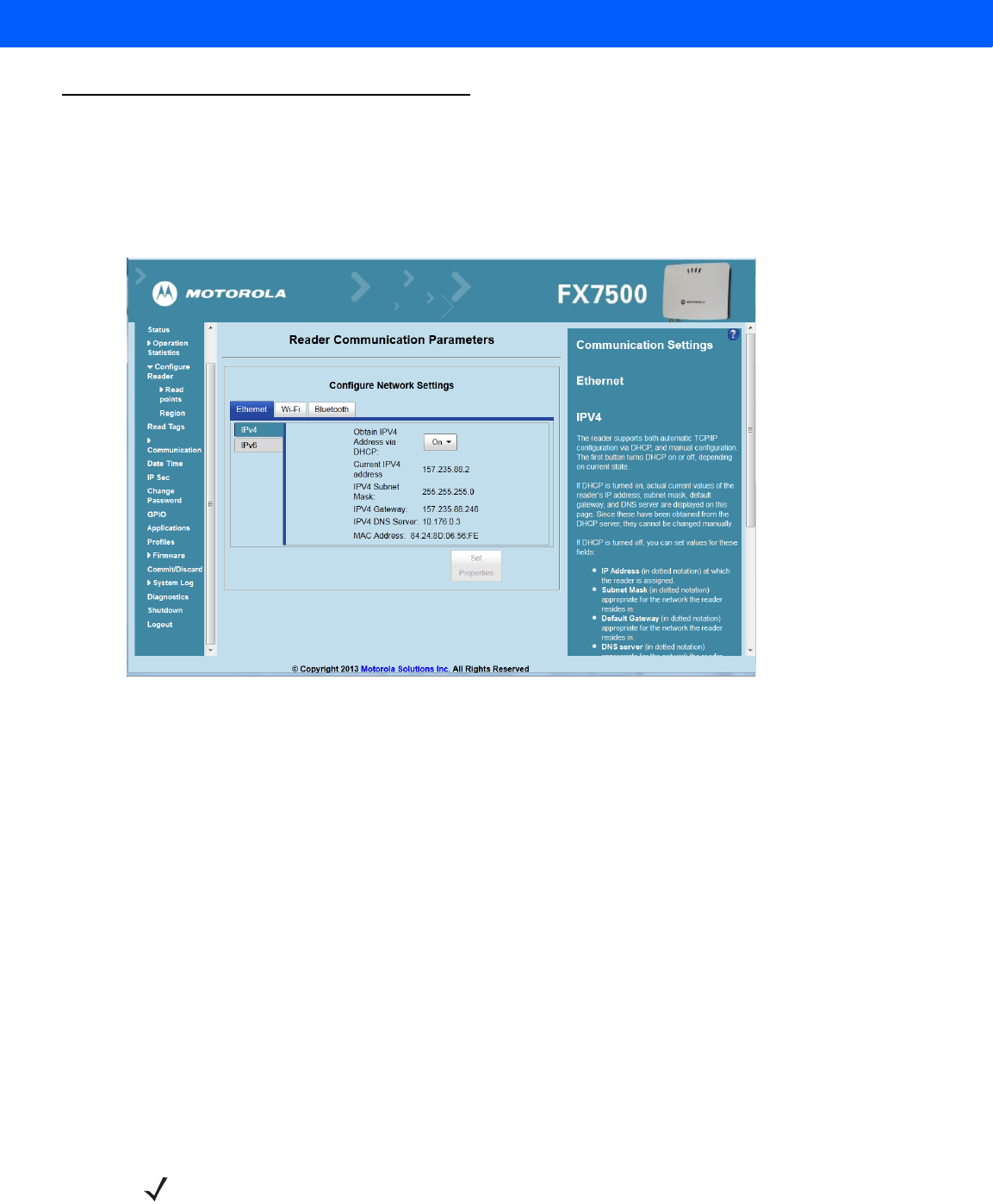
Communication Settings
Select Communication to view the Configure Network Settings window. This window has tabs for Ethernet, WiFi,
and Bluetooth. Each tab has options for IPV4 and IPV6.
Configure Network Settings - Ethernet Tab
Figure 4-18
Configure Network Settings - Ethernet Tab
IPV4
•
Obtain IPV4 Address via DHCP - The reader supports both automatic TCP/IP configuration via DHCP
and manual configuration. The DHCP button turns DHCP on and off.
If DHCP is turned on, this window displays actual current values of the reader's IP address, subnet mask,
default gateway, and DNS server. Because these are obtained from the DHCP server, they cannot be
changed manually.
If DHCP is turned off, you can set the following values for these fields.
•
Current IPV4 Address - IP address (in dotted notation) at which the reader is assigned.
•
IPV4 Subnet Mask - Subnet mask (in dotted notation) appropriate for the network in which the reader
resides.
•
IPV4 Default Gateway - Default gateway (in dotted notation) appropriate for the network in which the
reader resides.
•
IPV4 DNS Server - DNS server (in dotted notation) appropriate for the network in which the reader
resides.
•
MAC Address - The MAC address of the reader.
NOTE You must click Commit to update the network configuration (see Save Changes.) If the Commit is not
successful, the system indicates the problem and allows correcting it by repeating the operation. DHCP
and IP address updates do apply until the reader is rebooted.

4 - 24 FX7500 RFID Reader Integrator Guide
IPV6
•
Obtain IPV6 Address via DHCP - The reader supports both automatic TCP/IPV6 configuration via
DHCP and manual configuration. The DHCP button turns DHCP on and off.
If DHCP is turned on, this window displays actual current values of the reader's IPV6 address, prefix
length, default gateway, and DNS server. Because these are obtained from the DHCP server, they
cannot be changed manually.
If DHCP is turned off, you can set the following values for these fields.
•
Current IPV6 Address - IP address (in dotted notation) at which the reader is assigned.
•
Prefix Length - Prefix length appropriate for the network in which the reader resides.
•
IPV6 Default Gateway - Default gateway (in dotted notation) appropriate for the network in which the
reader resides.
•
IPV6 DNS Server - DNS server (in dotted notation) appropriate for the network in which the reader
resides.
•
MAC Address - The MAC address of the reader.
NOTE You must click Commit to update the network configuration (see Save Changes.) If the Commit is not
successful, the system indicates the problem and allows correcting it by repeating the operation. DHCP
and IP address updates do apply until the reader is rebooted.
NOTE Also enable automatic configuration for IPV6 through RA packets configuration. To enable or disable RA
packet configuration go to the Services window (see Services).
Administrator Console 4 - 25
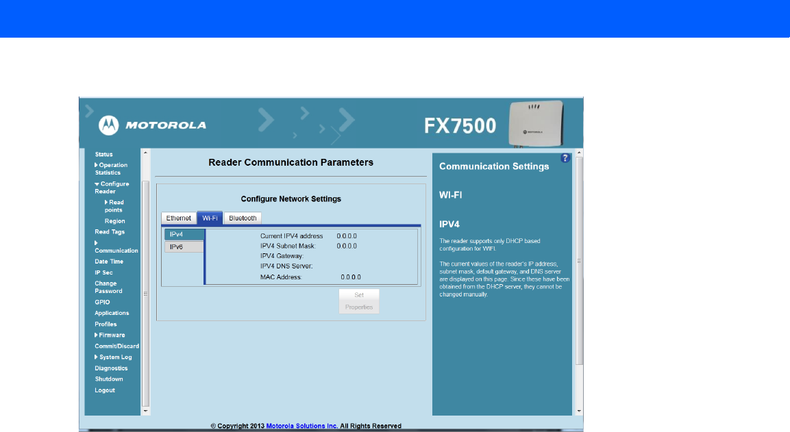
Configure Network Settings - Wi-Fi Tab
Figure 4-19
Configure Network Settings - Wi-Fi Tab
IPV4
The reader supports only DHCP-based configuration for WIFI. This window displays the current values of the
reader's IP address, subnet mask, default gateway, and DNS server. Since these are obtained from the DHCP
server, they cannot be changed manually.
IPV6
The reader supports only DHCP based configuration for WIFI. This window displays the current values of the
reader's IPV6 address, prefix length, default gateway, and DNS server. Since these are obtained from the
DHCP server, they cannot be changed manually.
4 - 26 FX7500 RFID Reader Integrator Guide
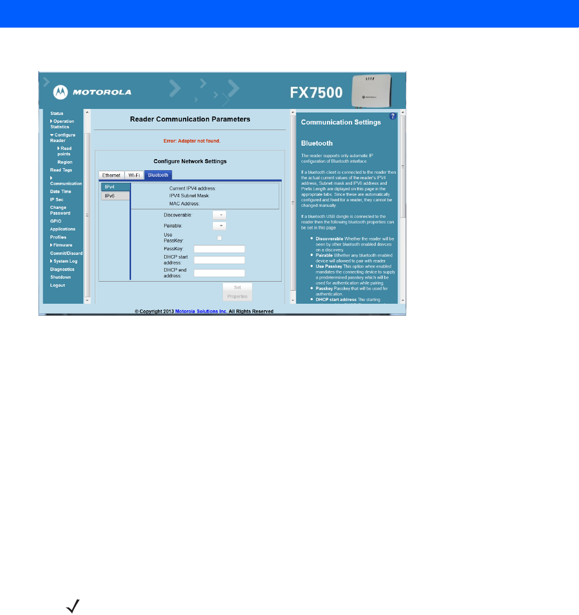
Configure Network Settings - Bluetooth Tab
Figure 4-20
Configure Network Settings - Bluetooth Tab
The reader supports only automatic IP configuration of the Bluetooth interface.
If a Bluetooth client is connected to the reader, this window displays the current values of the reader's IPV4
address, Subnet mask, IPV6 address, and prefix length in the appropriate tabs. Because these are
automatically configured for a reader, they cannot be changed manually.
If a Bluetooth USB dongle is connected to the reader, you can set the following Bluetooth properties in this
window:
•
Discoverable - Select whether the reader is seen by other Bluetooth-enabled devices on discovery.
•
Pairable - Select whether any Bluetooth-enabled device can pair with reader.
•
Use Passkey - Enable this option to mandate the connecting device to supply a pre-determined passkey
to use for authentication while pairing.
•
Passkey - The passkey to use for authentication.
•
DHCP start address - The starting address of the DHCP IP range out of which an IP is assigned to the
connecting device.
•
DHCP end address - The end address of the DHCP IP range out of which an IP is assigned to the
connecting device.
NOTE The DHCP IP range specified using the DHCP start address and DHCP end address options also
determine the IP of the Bluetooth interface of the reader. The first two octets of the IP address of the
reader Bluetooth interface are taken from the IP range specified and the last two octets use the reader
BD address.
Administrator Console 4 - 27
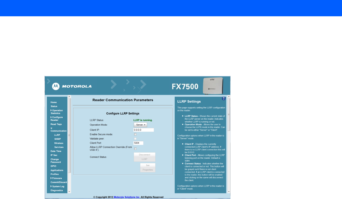
Configure LLRP Settings
Select LLRP to view and set the LLRP settings. By default, LLRP activates in server mode, where LLRP clients
can connect to the reader using the port number specified in the Client port field. You can also configure the
reader in LLRP client mode. In this case, configure the LLRP server address in this web page as well. LLRP
cannot be disabled since it is the primary native protocol for RFID for the reader.
Figure 4-21
Configure LLRP Settings Window
This window offers the following fields:
•
LLRP Status - Displays the current state of the LLRP server on the reader. Indicates whether LLRP is
running.
•
Operation Mode - Sets the LLPR mode in the reader to either Server or Client.
LLRP configuration options when the reader is in Server mode:
•
Client IP - Displays the currently connected LLRP client's IP address. If there is no LLRP client
connection, this is 0.0.0.0.
•
Client Port - Configures the LLRP listening port on the reader. The default is 5084.
•
Connect Status - Indicates whether the client is connected. This button is grayed out if there is no client
connected. If an LLRP client is connected to the reader, this button is enabled; click this button to
disconnect the client.
LLRP configuration options when the reader is in Client mode:
•
Server IP - Configures the IP address of the server to connect to.
•
Client Port - Configures the LLRP host port to connect to. The default is 5084.
•
Allow LLRP Connection Override (From USB IF) - This allows the reader to listen on an alternate port
(49152) on the virtual network (over USB) interface. When an LLRP client is connected over the primary
interface (Ethernet and primary LLRP port), a different client can override this connection on the alternate
interface (Virtual Network and alternate port 49152) if this option is enabled. This also permits overriding
a connection from a primary interface over an existing connection on an alternate interface. This option is
off by default. Changing this option restarts the LLRP service on the reader.
4 - 28 FX7500 RFID Reader Integrator Guide
•
Connect Status - Indicates whether the reader is connected to the LLRP host. This button toggles
between ConnectLLRP and DisconnectLLRP. Clicking ConnectLLRP initiates an LLRP connection to
the host server.
LLRP configuration options when the reader is in Secure mode:
•
Security Mode - Specifies whether LLRP communicates in secure or unsecure mode. Checking Enable
Secure Mode switches the LLRP port to 5085 by default. You can override the port value. LLRP in
secure mode supports ciphers that are compliant with TLS1.2.
•
Validate Peer - Specifies whether the validation of peer against the same certification authority issued
certificate is required. If you select the validate peer option, the secure LLRP service on the reader
allows connection for valid secure peer entities only if the certificate of the peer is issued from the same
certification authority that issued the certificate for the reader. By default the reader uses self-signed
certificates, and peer certificate based validation is disabled.
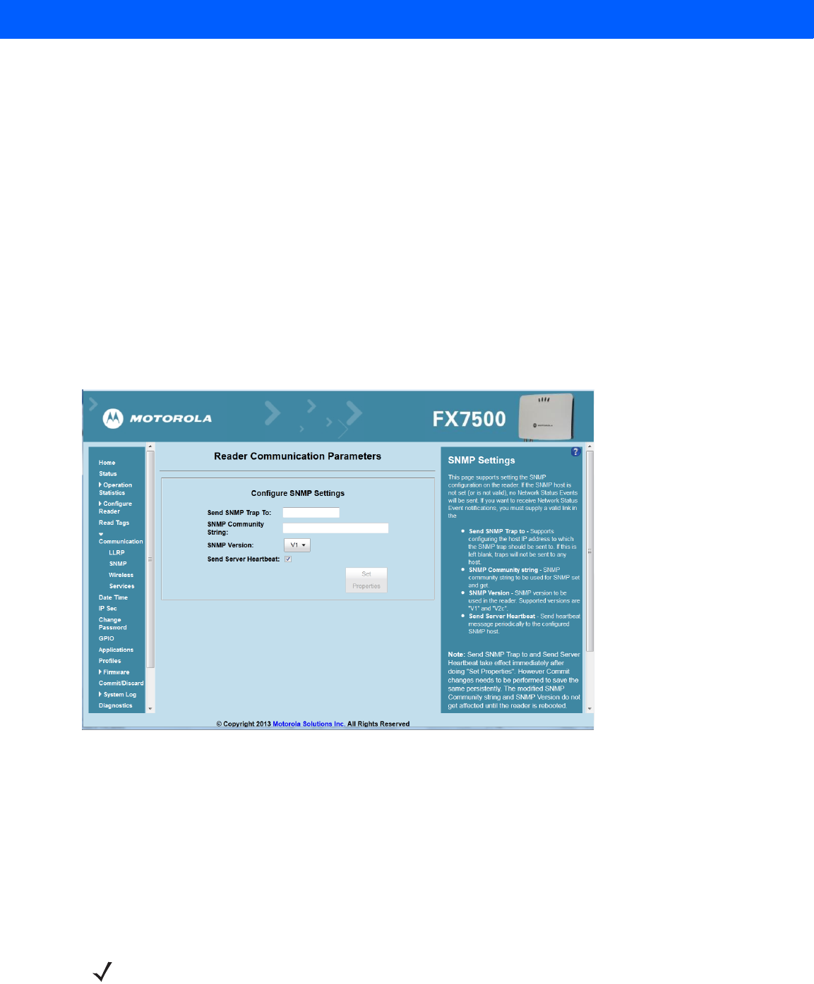
SNMP Settings
Select SNMP to view the Configure SNMP Settings window.
Figure 4-22
Configure SNMP Settings Window
Use this window to configure the SNMP host settings to allow sending network status events and receiving
network status event notifications:
•
Send SNMP Trap To - Configures the host IP address to which the SNMP trap is sent. Leave this blank to
send no traps to any host.
•
SNMP Community String - SNMP community string to use for SNMP set and get.
•
SNMP Version - SNMP version to use in the reader. Supported versions are V1 and V2c.
•
Send Server Heartbeat - Sends a heartbeat message periodically to the configured SNMP host.
NOTE Send SNMP Trap To and Send Server Heartbeat take effect immediately after clicking Set Properties.
However, perform a Commit to persist the changes. The modified SNMP Community String and SNMP
Version are not affected until the reader reboots.
Administrator Console 4 - 29
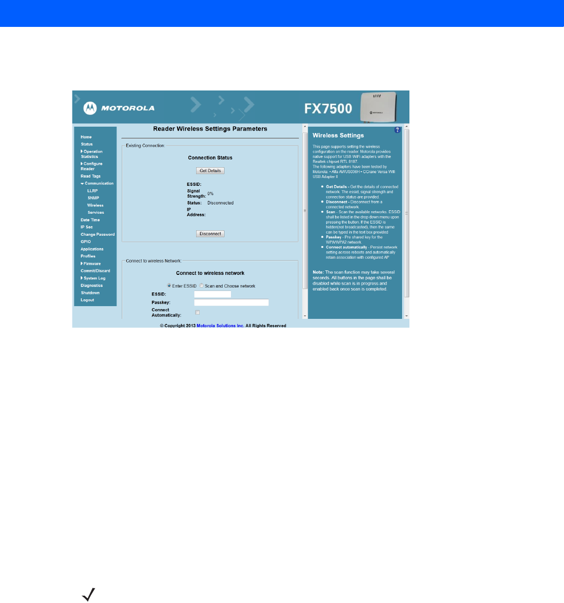
Wireless Settings
Select Wireless to view the Reader Wireless Settings Parameters window.
Figure 4-23
Wireless Settings Window
Use this window to set the wireless configuration on the reader. Motorola provides native support for USB WiFi
adapters with the Realtek chipset RTL 8187, and tested the following adapters:
•
Alfa AWUS036H
•
CCrane Versa Wifi USB Adapter II
The Wireless Settings window offers the following options:
•
Get Details - Click to get details of the connected network, including the ESSID, signal strength, and
connection status.
•
Disconnect - Click to disconnect from a connected network.
•
Scan and Choose Network - Scan the available networks. Clicking this lists the ESSID in the
drop-down menu. If the ESSID is hidden (not broadcasted), enter the ESSID in the text box provided.
•
Passkey - Pre-shared key for the WPA/WPA2 network.
•
Connect Automatically - Persist network setting across reboots and automatically retain association
with the configured AP.
NOTE The scan function can take several seconds. All buttons on the page are disabled while the scan is in
progress, and re-enabled when the scan completes.
4 - 30 FX7500 RFID Reader Integrator Guide
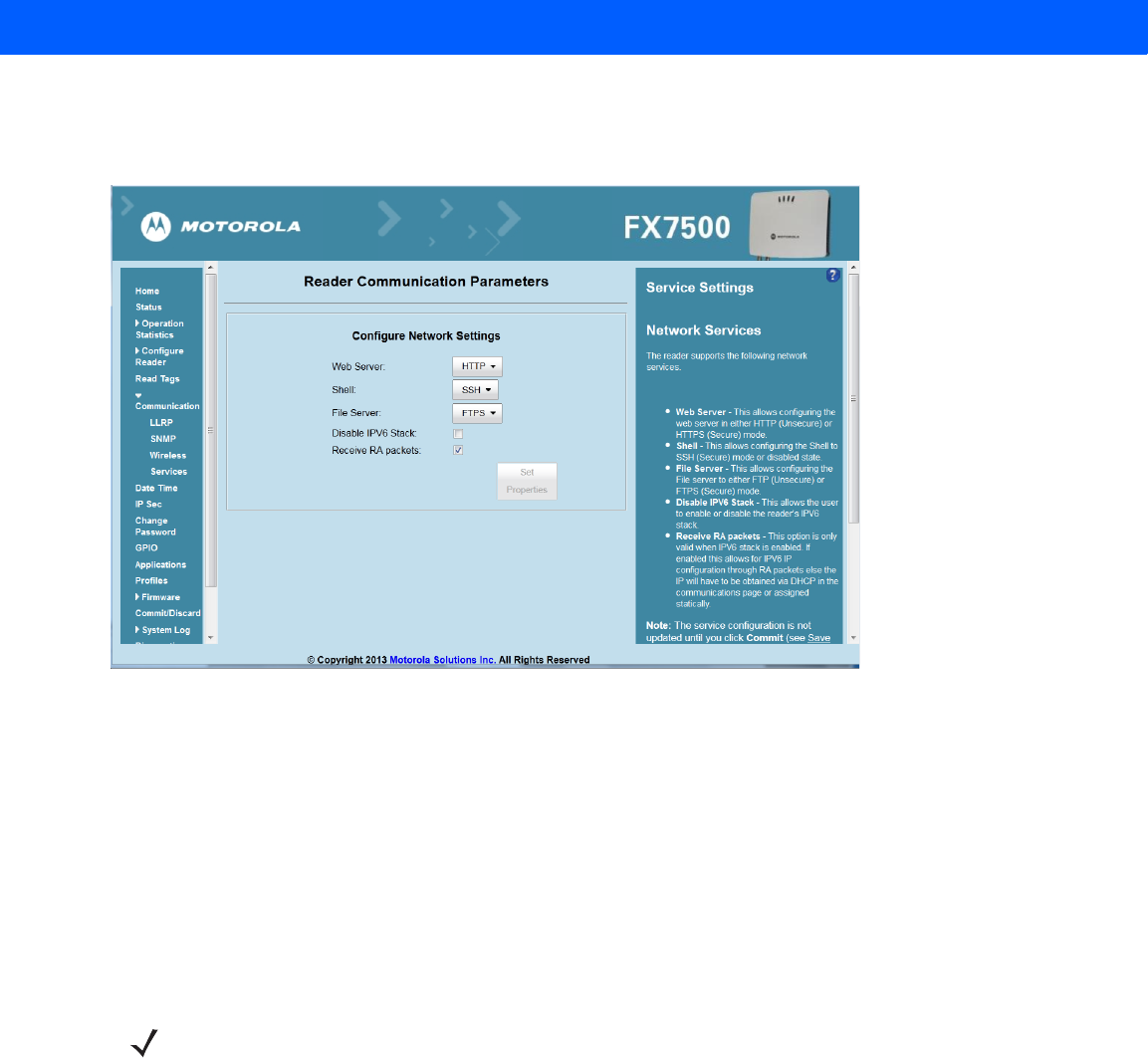
Network Services Settings
Select Services to view the Configure Network Service Settings window.
Figure 4-24
Configure Network Service Settings Window
The reader supports the following network services.
•
Web Server - Configures the web server in either HTTP (unsecure) (default) or HTTPS (secure) mode.
•
Shell - Sets the shell to SSH (secure) mode (default) or a disabled state.
•
File Server - Sets the file server to either FTP (unsecure) or FTPS (secure) (default) mode.
•
Disable IPV6 Stack - Select this to disable the reader's IPV6 stack. IPV6 stack is enabled by default.
•
Receive RA packets - This option is only valid when the IPV6 stack is enabled. Enable this to allow IPV6
IP configuration through RA packets; otherwise obtain the IP via DHCP in the Communication window or
assign statically. This is disabled by default.
NOTE You must click Commit to update the service configuration (see Save Changes.) If the Commit is not
successful, the system indicates the problem and allows correcting it by repeating the operation.
Administrator Console 4 - 31
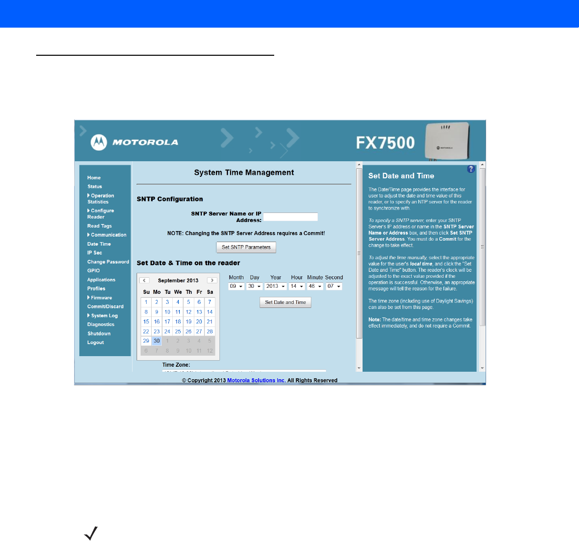
System Time Management
Select Date Time to view the System Time Management window. Use this window to set the date and time value
of the reader, or to specify an NTP server for the reader to synchronize with.
Figure 4-25
System Time Management Window
To specify an SNTP server, enter the SNTP server's IP address or name in the SNTP Server Name or IP
Address box, and then click Set SNTP Parameters. You must select Commit for the change to take effect.
To adjust the time manually, select the appropriate value for the user's local time, and click the Set Date and
Time button. This adjusts the reader's clock to the value provided if the operation is successful. Otherwise, an
appropriate message indicates the reason for the failure.
You can also set the Time Zone (including use of Daylight Savings) using the drop-down menu.
NOTE The date/time and time zone changes take effect immediately, and do not require a Commit.
4 - 32 FX7500 RFID Reader Integrator Guide
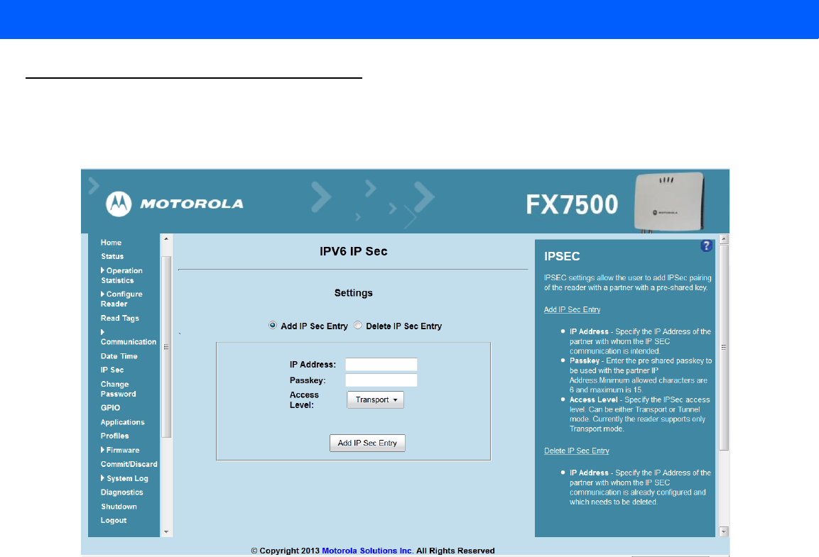
IPV6 IP Sec
Select IP Sec to view the IPV6 IP Sec window. IP Sec settings allow adding IPSec pairing of the reader with a
partner with a pre-shared key.
Figure 4-26
IPV6 IP Sec Window
To add an IP Sec entry:
1. Click the Add IP Sec Entry radio button.
2. In the IP Address field, specify the IP address of the partner with whom the IP SEC communication is
intended.
3. In the Passkey field, enter the pre-shared passkey (from 6 to 15 characters) to use with the partner IP
address.
4. In the Access Level drop-down list, select the IPSec access level. Options are Transport and Tunnel
mode. Currently the reader only supports Transport mode.
5. Click the Add IP Sec Entry button.
To delete an IP Sec entry:
1. Click Delete IP Sec Entry radio button.
2. In the IP Address field, specify the IP address of the partner with whom the IP SEC communication is
configured and is to be deleted.
3. Click the Delete IP Sec Entry button.
Administrator Console 4 - 33
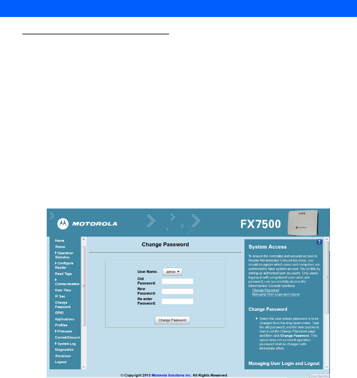
Change Password
To ensure the controlled and secured access to reader Administrator Console functions, designate which users
and computers are authorized to have system access by setting up authorized user accounts. Only users
logging in with a registered user name and password can successfully access Administrator Console functions.
FX7500 User Accounts
The FX7500 supports the different user accounts:
•
admin - This user has web access but no shell access, with full privileges to make changes on the
reader using the Administrator Console interface and to access to the reader using the FTP interface.
•
guest - This user has web access but no shell access, with read-only privileges in the Administrator
Console and can not make configuration changes. The guest user does not need a password to log in to
the Administrator Console.
•
rfidadm - This is the reader administrator, with shell access but no Administrator Console access.
rfidadm has full access to the /apps directory and read-only access to most of the other directories,
including the /platform, /usr, /lib, /etc, and /bin directories. The rfidadm user can use this account to
install and uninstall RFID programs and upload user applications.
Select Change Password to view the Change Password window.
Figure 4-27
Change Password Window
To set a user password:
1. In the User Name drop-down list, select the user for whom to change the password.
2. In the Old Password field, enter the existing password for that user.
3. In the New Password field, enter the new password, and again in the Re-Enter Password field.

4 - 34 FX7500 RFID Reader Integrator Guide
4. Click Change Password. The password changes immediately and does not require a Commit operation.
Managing User Login and Logout
Users must log in and log out of the system to ensure that system access is granted only to authorized users,
and that only one user is logged in at a time to ensure that multiple users do not make conflicting changes to
the system.
If the user performs no action for a period of time, the system automatically logs him or her out. The user must
log in again to use the Administrator Console.
Administrator Console 4 - 35
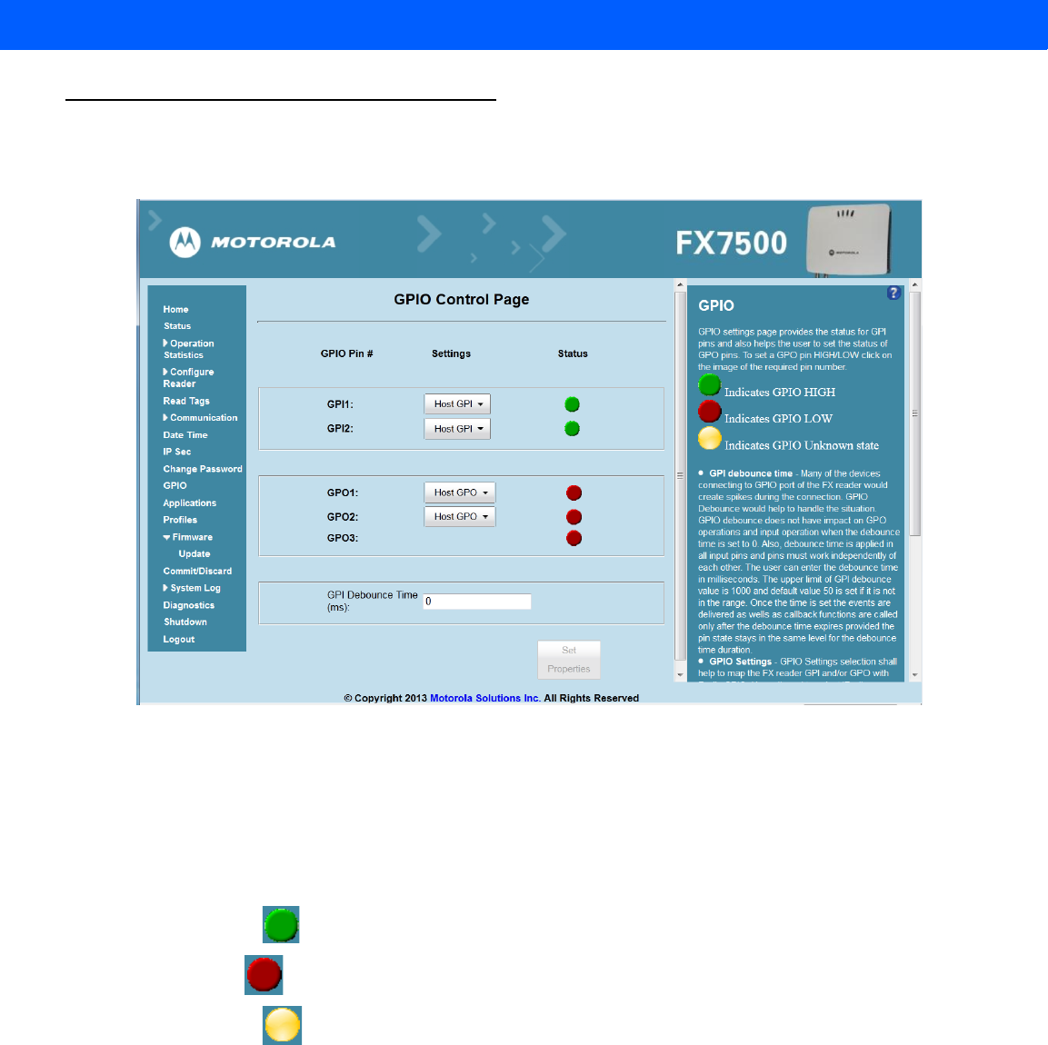
GPIO
Select GPIO to view the GPIO Control Page. This window allows viewing and setting the status for GPI pins.
Figure 4-28
GPIO Control Page
•
Settings - Map the reader GPI and/or GPO with the radio GPIO. Select either Radio or Host for GPIx or
GPOx where x = 0 or 1. An attempt to violate this condition changes the selection to either Host GPIx or
Host GPOx automatically. These settings are valid for FX7500 four port readers and are disabled if not
supported.
•
Status - To set a GPO pin high or low, click on the image next to the required pin number:
•Green indicates GPIO HIGH
•Red indicates GPIO LOW
•Yellow indicates GPIO unknown
•
GPI Debounce Time - Enter a value of up to 1000 milliseconds to minimize spikes that can occur when
a device connects to the GPIO port of the FX reader. The default is 50. Debounce time applies to all input
pins, and pins must work independently of each other. Events and callback functions occur only after the
debounce time expires, provided the pin state remains at the same level for the debounce time duration.
GPIO debounce does not impact GPO and input operations when set to 0.
•
Set Properties - Click this when all selections are made.
4 - 36 FX7500 RFID Reader Integrator Guide
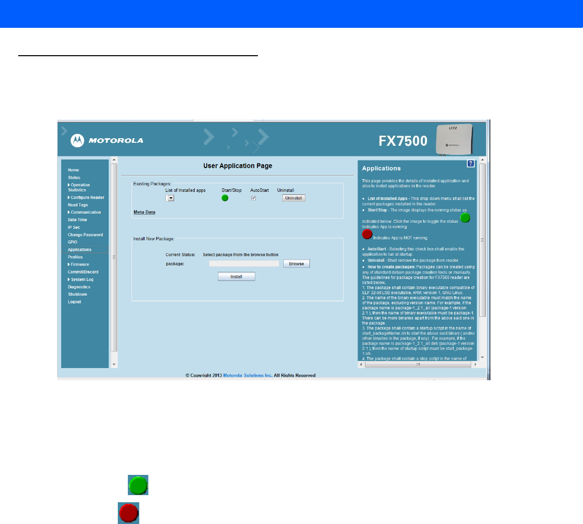
Applications
Select Applications to view the User Application Page. This window allows installing applications on the
reader and provides details of the installed application.
Figure 4-29
User Application Page
The Existing Packages section includes the following options:
•
List of Installed apps - The drop-down menu lists the current packages installed in the reader.
•
Start/Stop - The image displays the running status as follows. Click the image to toggle the status.
•Green indicates application is running
•Red indicates application is not running
•
AutoStart - Select this check box to run the application at startup.
•
Uninstall - Removes the package from the reader.
To create packages for the FX7500 reader, use any of the standard Debian package creation tools, or create
them manually.
•
The package must contain a binary executable compatible with ELF 32-bit LSB executable, ARM,
version 1, GNU Linux.
•
The name of the binary executable must match the name of the package, excluding the version name.
For example, if the package name is package-1_2.1_all (package 1 version 2.1), the name of the
binary executable must be package-1. There can be more than one binary in the package.
•
The package must contain a startup script in the name of start_packageName.sh to start the binary or
binaries in the package. For example, if the package name is package-1_2.1_all.deb (package 1
version 2.1), the name of the startup script must be start_package-1.sh.
Administrator Console 4 - 37
•
The package must contain a stop script in the name of stop_packageName.sh to stop the binary or
binaries in the package. For example, if the package name is package-1_2.1_all.deb (package 1
version 2.1), the name of stop script must be stop_package-1.sh.
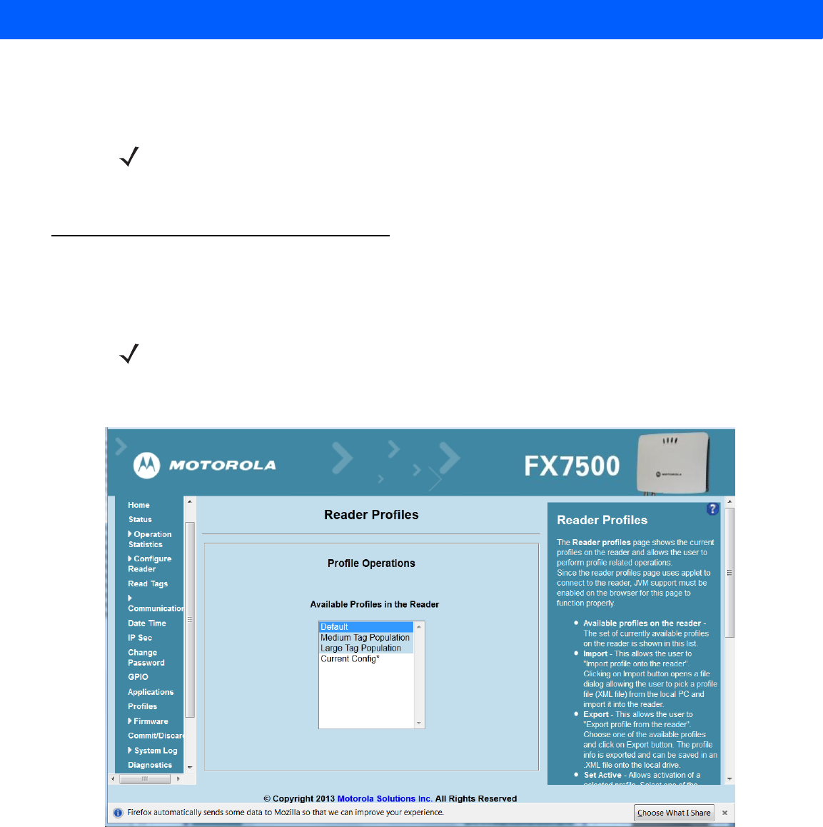
Reader Profiles
Select Profiles in the selection menu to view the Reader Profiles window, which shows the current profiles on
the reader and allows performing profile-related operations.
The window displays a set of provided configuration files, or profiles, that a user can re-use and/or modify
depending on the reader application or use case. The profiles serve as configuration examples.
Figure 4-30
Reader Profiles Window
The Reader Profiles window functions are:
•
Available Profiles in the Reader - Displays the available reader profiles.
•
Import - Click to open a file dialog and pick a profile (XML file) from the local PC and import it into the
reader.
•
Export - Select an available profile and click Export to export profile information and save an XML file
onto the local drive.
NOTE The reader executes the packages with the privileges of rfidadm user account. See the user accounts
section for information on rfidadm user privileges.
NOTE Because the Reader Profiles window uses an applet to connect to the reader, enable JVM support on
the browser in order for this window to function properly.

4 - 38 FX7500 RFID Reader Integrator Guide
•
Set Active - Activates a selected profile. Select an available profile and click Set Active to load the profile
content in the reader.
•
Delete - Select an available profile and click Delete to delete the profile.
Profiles can specify a number of reader parameters, including RF air link profiles. Air link profiles cannot be
configured using LLRP or web page interface. See Appendix E, RF Air Link Configuration for more information
about air link profile configuration.
FIPS Support on FX7500
The FX7500 supports FIPS 140-2 Level 1 for the following interfaces:
•
HTTPS
•
FTPS
•
SSH
•
LLRP Server
•
IPSec
•
SNMP
To enable or disable FIPS support in the reader profile, export the profile XML (CurrentConfig) from the
reader and set FIPS_MODE_ENABLED to 1 to enable FIPS, or 0 to disable FIPS. Then import the XML to the
reader and activate. Changing the FIPS mode restarts the reader. By default, FIPS is disabled.
CAUTION Swapping profiles between readers using static IP addresses is not recommended. Activating a profile
with a static IP address changes the IP of the reader, and if not done properly can make the reader
inaccessible.
NOTE Current Config is a special logical profile that can only be exported to the PC. This cannot be imported,
activated, or deleted. Only the profile name indicates that it is the active profile.
Administrator Console 4 - 39
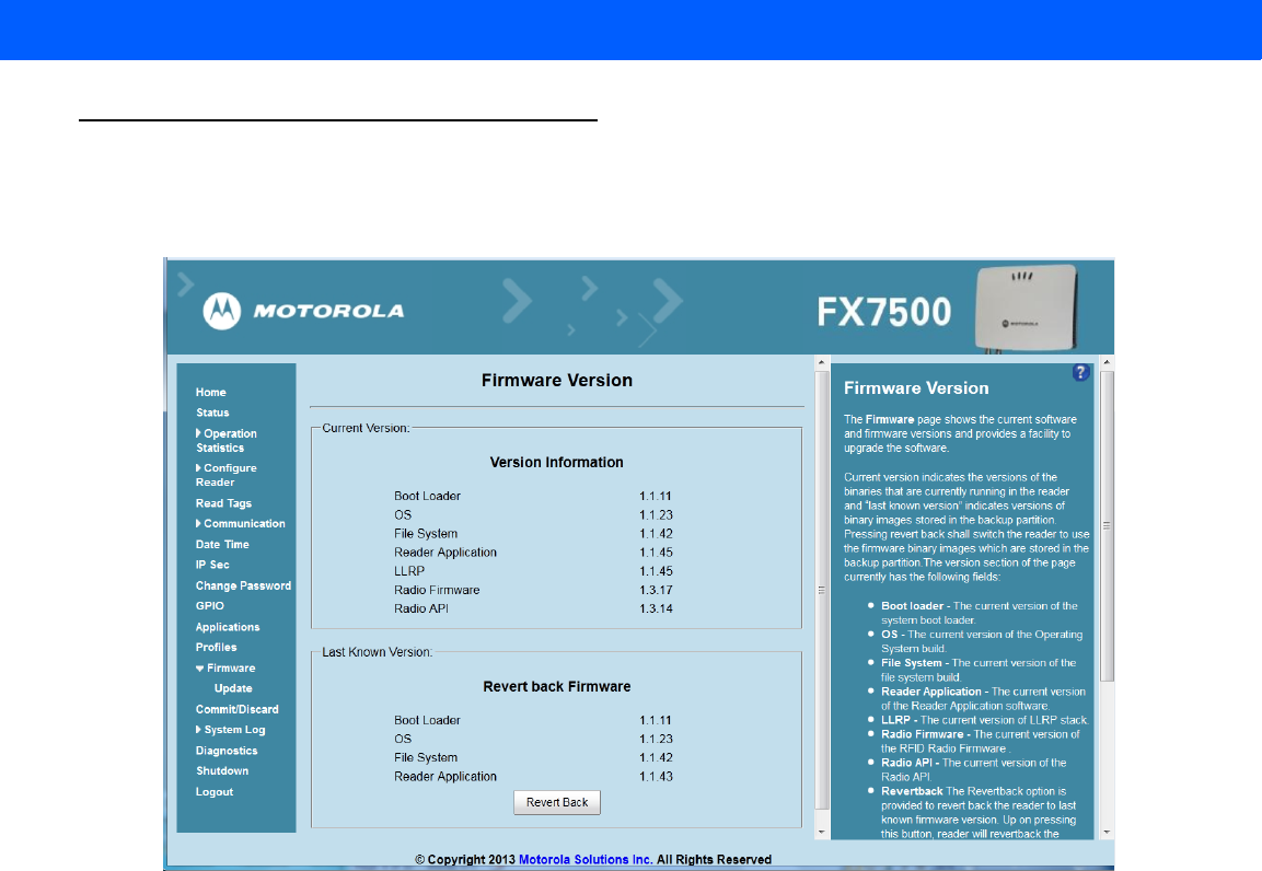
Firmware Version/Update
The Firmware Version window displays the current software and firmware versions and allows upgrading to
new firmware. From the selection menu, click Firmware.
Figure 4-31
Firmware Version
Current Version indicates the binary versions currently running in the reader. Last Known Version indicates
binary image versions stored in the backup partition. This window provides version information on the following
firmware:
•
Boot Loader
•
OS
•
File System
•
Reader Application
•
LLRP
•
Radio Firmware
•
Radio API
Select Revert Back to revert the firmware to last known version. The reader automatically reboots. This option
is not enabled if the reader detects an error in the previous firmware update.

4 - 40 FX7500 RFID Reader Integrator Guide
Firmware Update
The Firmware Update window allows upgrading to new firmware. From the selection menu, click Update.
The reader supports three different methods of updating the firmware:
•
Update using a USB drive.
•
File-based update that allows uploading the firmware files from the PC (or a network location) to the
reader and running the update.
•
FTP / FTPS / SCP server-based update.
For instructions on updating the firmware, see Appendix C, FTP Firmware Upgrade.
NOTE You must be logged in with Administrator privileges in order to access this window. See Change
Password on page 4-33.
Administrator Console 4 - 41
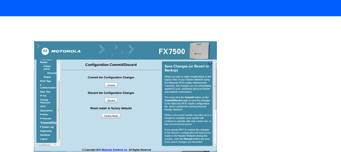
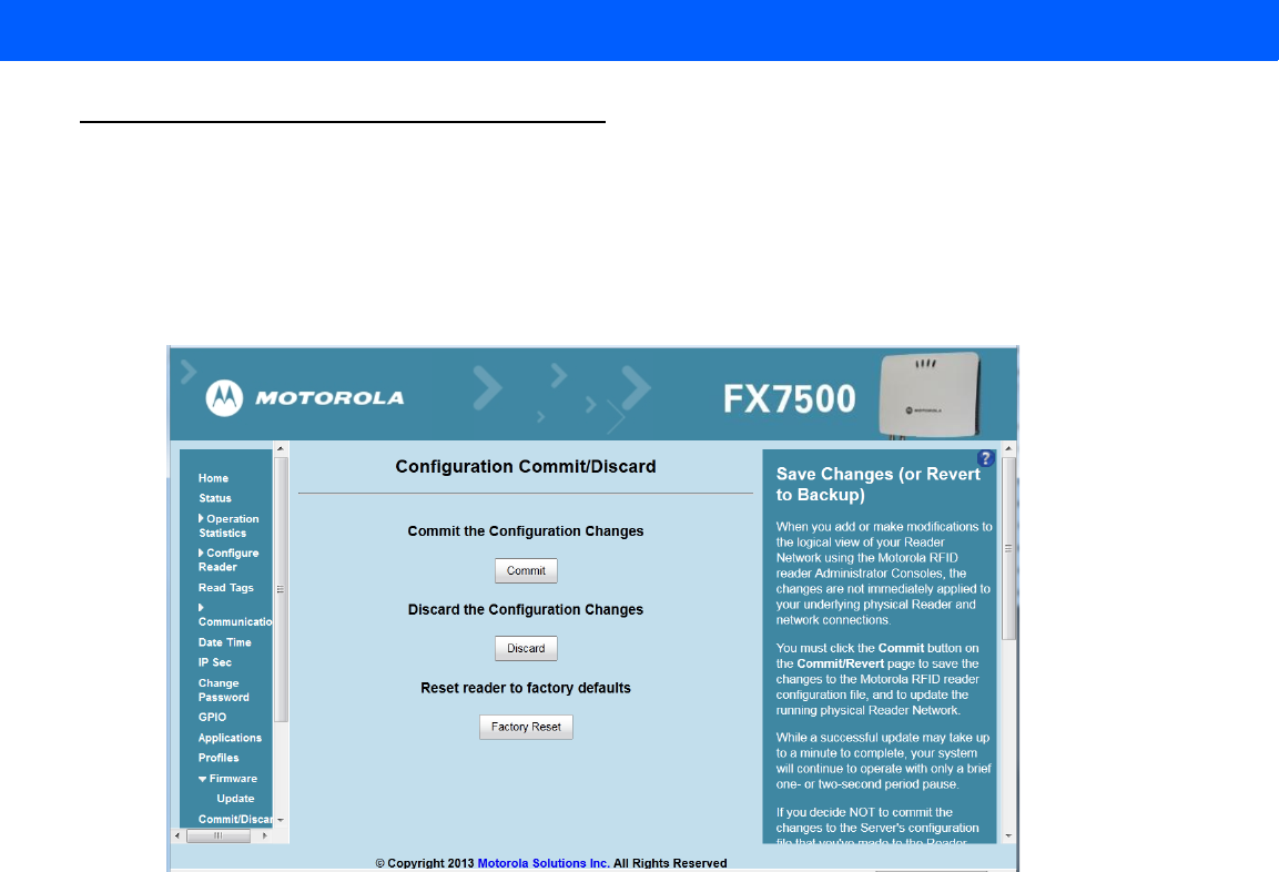
Commit/Discard
Changes made to the logical view of the reader network using the Administrator Console do not immediately
apply to the reader and network connections. To apply reader configuration modifications, select
Commit/Discard, then click Commit to save the changes to the reader configuration file, and to update the
running physical reader network. While a successful update can take up to a minute to complete, the system
continues to operate with a brief one or two second pause.
Figure 4-32
Configuration Commit/Discard Window
To discard changes to the server's configuration file made to the reader network during this session, click
Discard.
Click Factory Reset to reset the reader to factory defaults. This clears all customized user settings, including
configuration, and installed applications. The reader reboots automatically.
4 - 42 FX7500 RFID Reader Integrator Guide
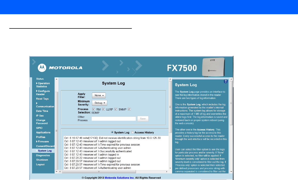
System Log
The System Log window lists reader log information.
Figure 4-33
System Log Window
This window offers the following options:
•
Apply Filter - Select a filter option from the drop-down menu to view logs for particular process and/or
severity:
• None - Do not apply a filter.
• Minimum Severity only - The severity level filters the log.
• Process Selection only - Selected pre-defined processes and comma-separated process strings
filters the logs.
• Minimum Severity & Process Selection - both severity and process selection are considered in the
filter.
If you select Process Selection only or Minimum Severity & Process Selection and the process
string is empty with no pre-defined process selection, then the pre-defined process list filters the logs.
•
Minimum Severity - Select the severity level on which to filter.
•
Process Selection - Select the types of processes to filter upon.
•
Other process - To filter for specific processes, enter the process in this text box using a
comma-separated process list string with no spaces. If the log file is empty for the selected filter option,
an error message appears in the log text area. Click Save to save the filter settings, which persist upon
reader reboot.
Administrator Console 4 - 43
•
Log area - Select a radio button for one of the two types of log information offered:
•System Log - Includes the log information generated by the reader internal instructions. This stores up
to 1 MB of log information, and overwrites the oldest logs first. The log information is saved and
restored on proper system reboot (via the Administrator Console).
•Access History - Provides a history log for reader access, including every successful access to the
reader through the Administrator Console.
•
Select the Refresh Log to refresh the information in the log, or Purge Logs to clear the information.
•
To copy the log file to a specific location on the host select an option from the Export drop-down. Enter
the location in the File Path field, then select the Export File button.
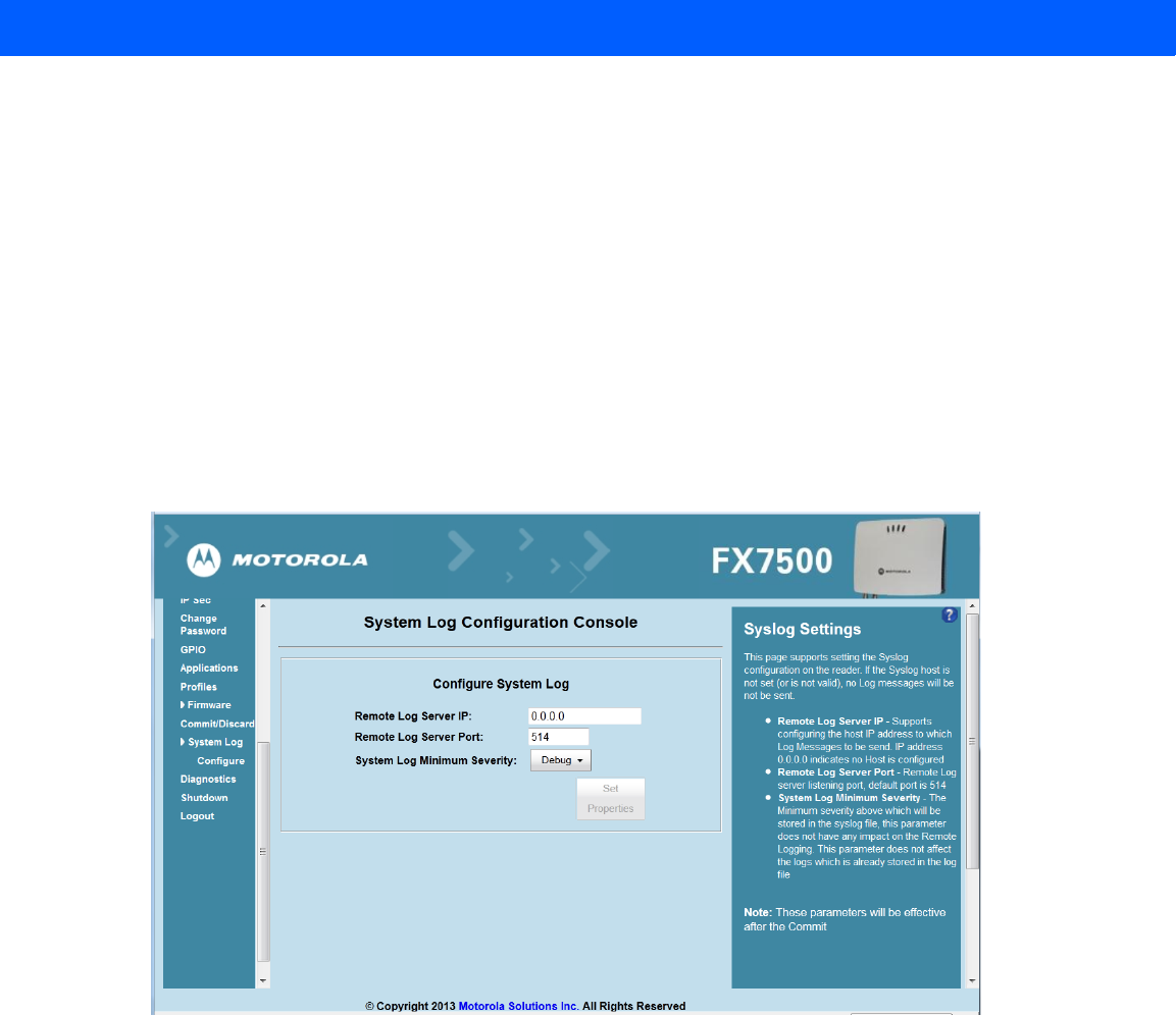
Configure System Log
This window configures system log settings. If the system log host is not set (or is not valid), log messages are
not sent.
Figure 4-34
Configure System Log Window
This window offers the following options:
•
Remote Log Server IP - Configures the host IP address to which log messages are sent. IP address
0.0.0.0 indicates that no host is configured.
•
Remote Log Server Port - Remote log server listening port. The default port is 514.
•
System Log Minimum Severity - The minimum severity above which data is stored in the log file. This
option does not impact remote logging or the logs already stored in the log file.
You must select Commit to activate these settings.
4 - 44 FX7500 RFID Reader Integrator Guide
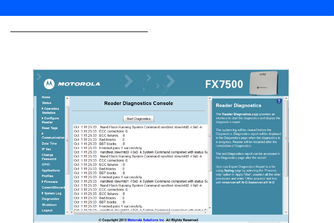
Reader Diagnostics
Select Diagnostics to view the Reader Diagnostics window, which allows running diagnostics and viewing
the diagnostics report.
Figure 4-35
Reader Diagnostics Window
Selecting Start Diagnostics clears the system log and displays the diagnostics report. The reader reboots
when the diagnostics completes. Return to the Diagnostics window to view the diagnostics report.
To export the diagnostics report to a file, on the System Log window, select Process Selection only in Apply
Filter, de-select all other processes, and in the Other Process text box enter:
rmserver.elf: N-D,llrpserver.elf: N-D
Administrator Console 4 - 45
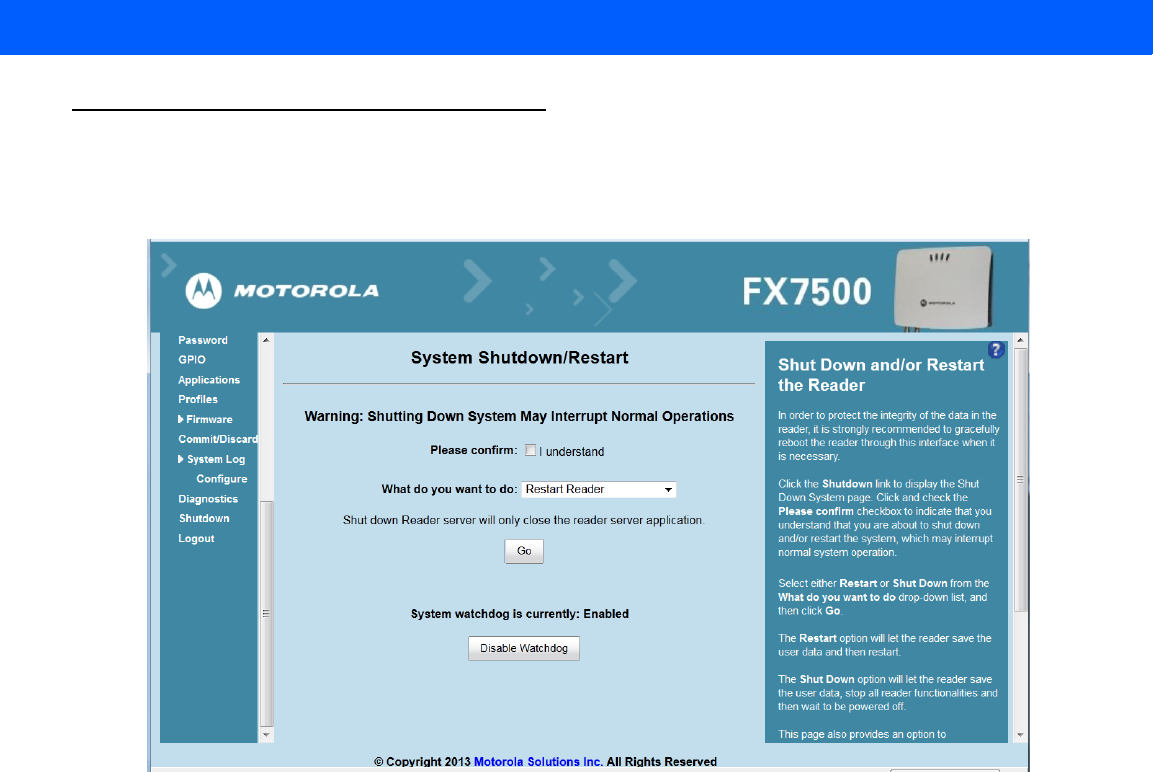
Shutdown
To protect the integrity of the reader data, gracefully reboot the reader via the Administrator Console when
necessary.
Figure 4-36
System Shutdown/Restart Window
To shut down or restart the reader:
1. Click the Shutdown link to display the System Shutdown/Restart window.
2. Check the Please Confirm check box to accept the system shut down and/or restart the system (this may
interrupt normal system operation).
3. Select one of the following options from the What do you want to do drop-down list:
•
Restart Reader - saves the user data and then restarts.
•
Shut down Reader server - the reader saves the user data, stops all reader functions, and waits to be
powered off.
4. Click Go.
This window also provides an option to enable or disable the reader watchdog.

4 - 46 FX7500 RFID Reader Integrator Guide

CHAPTER 5 TROUBLESHOOTING
Table 5-1 provides FX7500 troubleshooting information.
Table 5-1
Troubleshooting
Problem/Error Possible Causes Possible Solutions
Reader error LED lights after the
reader is in operation. The CPU cannot
communicate. Refer to the system log for error messages.
Reader error LED stays lit on
power up. An error occurred during the
power up sequence. Refer to the system log for error messages.
Cannot connect to the reader. User name and password is
unknown. The default user name is
admin
and the
default password is
change
. To change the
user name and password, see
Communications Connections on page
3-5
.
Reader is not reading tags. The tag is out of its read
range.
Antennas are not
connected.
Tags are damaged.
Tags are not EPCgen2.
If reading with the reader’s
web page, Java JRE 1.6 or
later is not installed.
Move the tag into read range. See
Read
Tags on page 4-21
.
Connect antennas.
Confirm that tags are good.
Confirm that tags are EPCgen2.
Install Java JRE 1.6.
Cannot access the
Administrator
Console
.The IP address is unknown. See
Communications Connections on
page 3-5
to view the IP address, or use the
host name to connect to the reader.

5 - 2 FX7500 RFID Reader Integrator Guide
Certain real time applications are
no longer functional. The node address, IP
address, or other reader
configuration parameter(s)
were changed using the
Administrator Console
, and
the application expects the
previous configuration.
Update the settings within the application.
Refer to the application manual.
The user closed the browser
without logging out of the
Administrator Console
, so
other applications cannot
connect to the reader.
Log out of the
Administrator Console
. The
applications can use the
Force Login
option
to log in even when the user closes the
browser without logging out.
Force Login
option is supported for the administrative
user.
Cannot log into
Administrator
Console
. The user forgot the
password. Press and hold the reset button for more
than 8 seconds. This resets the reader
configuration to factory defaults, including
the password. This also removes the
contents of the
apps
partition.
Unable to add SNTP server,
reader returning error. SNTP server is not
reachable.
SNTP server name is not
resolvable via DNS server.
DNS server is not
reachable.
Ensure the SNTP server is accessible.
Ensure the DNS server name is configured
in TCP/IP configuration.
Ensure the DNS server is accessible.
Operation failed. A user operation did not
complete, typically due to
invalid input.
Validate all inputs and retry the operation. If
it is not successful, see
Service Information
on page xi
.
Invalid User Name and/or
Password - Try again. The user name and/or
password were not found in
the system, or do not match
the current user registry.
Accurately retype login information. If this is
not successful, see
Service Information on
page xi
.
Session has Timed-out - Log in
again. The current session was
inactive beyond the time-out
period (15 minutes), so the
system automatically logged
out.
Log in again. As a security precaution to
protect against unauthorized system
access, always log out of the system when
finished.
User name is not correct. The user name does not
match the current user
registry (illegal characters,
too long, too short,
unknown, or duplicate.)
User forgot the user ID.
Accurately retype the user name.
See
Service Information on page xi
.
Table 5-1
Troubleshooting (Continued)
Problem/Error Possible Causes Possible Solutions

Troubleshooting 5 - 3
Not a legal IP address
(1.0.0.0 - 255.255.255.255).
Cannot reach the specified IP
address.
The SNMP Host Link is not valid.
The IP address entered is
either formatted inaccurately
or cannot be accessed
(pinged).
Accurately retype the IP address, and make
sure the host device is connected and
online. If this is not successful, see
Service
Information on page xi
.
Invalid network mask. The network mask entered
is not formatted correctly. Confirm the correct network mask from the
network administrator and enter it correctly.
Invalid SNMP version number. The version number for
SNMP protocol is not a
supported version.
Use version number 1 for SNMP version 1,
and 2 for SNMP version 2c.
Invalid description. The description contained
invalid characters (<,>,or'). Correct the description.
Invalid password. The password does not
match the current user
registry (illegal characters,
too long, or too short.)
User forgot the password.
Accurately retype the password.
See
Service Information on page xi
.
Name has already been used.
Serial number has already been
used.
IP address has already been
used.
The name, serial number, or
IP address entered already
exists in the system.
Enter a unique value for the new name,
serial number, or IP address.
Select an item from the list. The system requires
selecting an item from the
list box before continuing.
Select an item from the list box, and then
continue.
Last command is pending. Try
again later. The system did not finish
processing the previous
command.
Wait a few moments for the previous
command to complete before sending
another command.
Another administrator is currently
logged in. Try again later. The system does not allow
more than one administrator
to log in at a time.
Wait until the other administrator logs out
(or times out) before logging in.
Backup configuration file does
not exist. The system cannot revert to
a backup configuration
unless a backup file exists.
Commit the new configuration to create a
backup file.
Failed to confirm the new
password. The system requires
entering the password
identically two times.
Accurately retype the password twice.
Network configuration change(s)
have not been saved. The user requested log out
prior to committing/
discarding the changes
made during the session.
Select one of the
Commit/Discard
options.
Table 5-1
Troubleshooting (Continued)
Problem/Error Possible Causes Possible Solutions

5 - 4 FX7500 RFID Reader Integrator Guide
New password is the same as the
old one. The system requires
entering a new password
(different from the existing
password) during the
Change Password
operation.
Enter a password that is different from the
existing password.
Old password is not correct. The system requires
entering the existing
password during the
Change
Password
operation.
Accurately retype the existing password.
Unspecified error occurred -
code: #### A specific error message is
missing for the given status
code.
Note the code number, and contact
Motorola Solutions support. See
Service
Information on page xi
.
The requested page was not
found.
Internal Web Server Error.
The system experienced an
internal web server error. Contact Motorola Solutions support.
See
Service Information on page xi
Request method was NULL.
No query string was provided.
The system does not permit
executing a proxy program
from the command line
rather than the web server.
No action required. The system is reporting
that this action is not permitted.
Content length is unknown. The system cannot accept
an incorrectly formatted
HTTP POST request (from
an unsupported browser
application).
Use a GET request instead, or update the
software.
Couldn't read complete post
message. The system stopped a
POST operation before
completion.
Retry the operation, and allow it to
complete.
Unhandled reply type. The system generated an
unexpected value. Contact Motorola Solutions support.
See
Service Information on page xi
.
Failed to open port.
Failed to connect.
Failed to transmit.
Failed to receive.
Error during Receive of
Command.
Error during receive of
command. Contact Motorola Solutions support.
See
Service Information on page xi
.
Invalid Device Address. The device address
information (parent) is
invalid, missing, or
formatted inaccurately.
Contact Motorola Solutions support.
See
Service Information on page xi
.
Table 5-1
Troubleshooting (Continued)
Problem/Error Possible Causes Possible Solutions

Troubleshooting 5 - 5
Command parsing state error.
Missing argument for the
command.
Command internal type cast
error.
Missing operator.
Unknown operator.
A command was formatted
inaccurately. Contact Motorola Solutions support.
See
Service Information on page xi
.
The action must be confirmed. The user must confirm the
requested action before it is
executed.
Select the confirmation option when issuing
this request.
Invalid network adapter when
navigating to the Bluetooth
configuration page.
The Bluetooth dongle is not
plugged in or not supported. Plug in a supported Bluetooth dongle and
refresh the browser.
Wireless scan error. Wireless dongle is not
plugged in or not supported. Plug in a supported wireless dongle and
repeat the wireless scan.
OS update in progress. Firmware update on the
reader is ongoing. The
current operation is not
permitted.
Wait for the firmware update to complete
and then retry the operation.
Cannot change password. Cannot change password
for guest. Guest does not need a password to log in to
the Administrator Console.
Table 5-1
Troubleshooting (Continued)
Problem/Error Possible Causes Possible Solutions
NOTE If problems still occur, contact the distributor or call the local contact. See page xi for contact information.

5 - 6 FX7500 RFID Reader Integrator Guide

APPENDIX A TECHNICAL SPECIFICATIONS
FX7500 Kits
KT-FX75004US-01 4-Port US Reader Kit
•
FX7500-42310A30-US (4-port US reader)
•
AN480-CL66100WR (wide-band AN-480 antenna)
•
BRKT-70661-01R (antenna mounting bracket)
•
CBLRD-1B4001800R (15-foot RF cable)
•
50-14000-159R (power supply)
•
23844-00-00R (US power cord)
KT-FX75002US-01 2-Port US Reader Kit
•
FX7500-22310A30-US (2-port US reader)
•
AN480-CL66100WR (wide-band AN-480 antenna)
•
BRKT-70661-01R (antenna mounting bracket)
•
CBLRD-1B4001800R (15-foot RF cable)
•
50-14000-159R (power supply)
•
23844-00-00R (US power cord)
KT-FX75004WR-01 4-Port Global Reader Kit
•
FX7500-42315A30-US (4-port global reader)
•
AN480-CL66100WR (wide-band AN-480 antenna)
•
BRKT-70661-01R (antenna mounting bracket)
•
CBLRD-1B4001800R (15-foot RF cable)
•
50-14000-159R (power supply)

A - 2 FX7500 RFID Reader Integrator Guide
KT-FX75002WR-01 2-Port Global Reader Kit
•
FX7500-22315A30-US (2-port global reader)
•
AN480-CL66100WR (wide-band AN-480 antenna)
•
BRKT-70661-01R (antenna mounting bracket)
•
CBLRD-1B4001800R (15-foot RF cable)
•
50-14000-159R (power supply)
Technical Specifications
The following tables summarize the RFID reader intended operating environment and technical hardware
specifications.
Table A-1
Technical Specifications
Item FX
Physical and Environmental Characteristics
Dimensions 7.7 in. L x 5.9 in. W x 1.7 in. D
(19.56 cm L x 14.99 cm W x 4.32 cm D)
Weight 1.9 lbs ± 0.1 lbs (0.86 kg +/- 0.05 kg)
Base Material Die cast aluminum, sheet metal and plastic
Visual Status Indicators Multi-color LEDs: Power, Activity, Status, and Applications
Mounting Keyhole and standard VESA (75 mm x 75 mm)
FX Environmental Specifications
Operational Temperature -4° to +131° F / -20° to +55° C
Storage Temperature -40° to +158° F / -40° to +70° C
Humidity 5 to 95% non-condensing
Shock and Vibration MIL-STD-810G
Connectivity
Communications 10/100 BaseT Ethernet (RJ45) w/ POE support
USB Client (Type B), USB Host (Type A)
General Purpose I/O 2 inputs, 3 outputs, optically isolated (terminal block)
External 12V ~ 48 VDC power available for GPIO
Power POE or POE+
12 VDC to 48 VDC, or 24 VDC Universal Power Supply
Antenna Ports FX 7500-2: 2 mono-static ports (reverse polarity TNC)
FX 7500-4: 4 mono-static ports (reverse polarity TNC)

Technical Specifications A - 3
Hardware/OS and Firmware Management
Memory Flash 512 MB; DRAM 256 MB
Operating System Linux
Firmware Upgrade Web-based and remote firmware upgrade capabilities
Management Protocols RM 1.0.1 (with XML over HTTP/HTTPS and SNMP binding)
Network Services DHCP, HTTPS, FTPS, SFPT, SCP, SSH, HTTP, FTP, SNMP and NTP
Network Stack IPv4, IPv6
Security Transport Layer Security Ver. 1.2, FIPS 140-2 Level 1
Air Protocols EPCglobal UHF Class 1 Gen2, ISO 18000-6C
Frequency (UHF Band) Global Reader: 902 MHz to 928 MHz (Maximum, supports countries that use a part
of this band)
865 MHz to 868 MHz
US (only) Reader: 902 MHz to 928 MHz
Transmit Power Output 10 dBm to +31.5 dBm (POE+, 12V ~ 48V External DC,
Universal 24 VDC Power Supply;
+10 dBm to +30.0 dBm (POE)
Max. Receive Sensitivity -82 dBm
IP addressing Static and Dynamic
Host Interface Protocol LLRP v1.0.1
API Support Host Applications – .NET, C and Java EMDK;
Embedded Applications – C & Java SDK
Warranty
The FX7500-4 and FX7500-2 are warranted against defects in workmanship and materials for a period of one
year (12 months) from date of shipment, provided the product remains unmodified and is operated under normal
and proper conditions.
For the complete Motorola hardware product warranty statement, go to:
http://www.motorolasolutions.com/warranty
Recommended Services
Support Services Service from the Start Advance Exchange On-Site System Support Support
Advanced Services RFID Design and Deployment Services
Table A-1
Technical Specifications (Continued)
Item FX
A - 4 FX7500 RFID Reader Integrator Guide
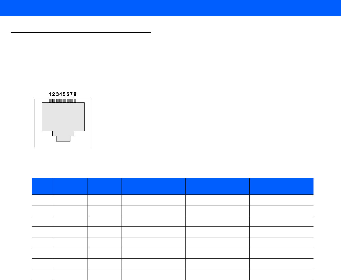
Cable Pinouts
10/100bT Ethernet / POE Connector
The 10/100BT Ethernet / POE connector is an RJ45 receptacle. This port complies with the IEE 802.3af
specification for Powered Devices.
Figure A-1
Ethernet Connections
Table A-2
10/100bT Ethernet / POE Connector Pinout
Pin Pin Name Direction Description POE Mode A
Function
POE Mode B
Function
Pin 1 TX-P O TX Data Positive Positive Vport
Pin 2 TX-N O TX Data Negative Positive Vport
Pin 3 RX-P I RX Data Positive Negative Vport
Pin 4 NC - No Connect Positive Vport
Pin 5 NC - No Connect Positive Vport
Pin 6 RX_N I RX Data Negative Negative Vport
Pin 7 NC - No Connect Negative Vport
Pin 8 NC - No Connect Negative Vport
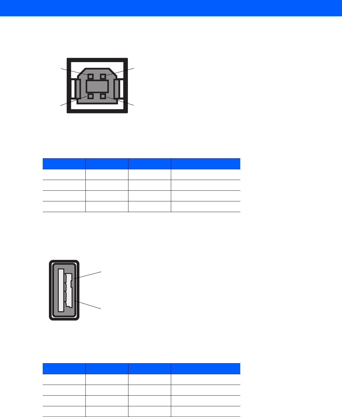
Technical Specifications A - 5
USB Client Connector
The USB Client port is supplied on a USB Type B connector.
Figure A-2
USB Client Connector
USB Host Connector
The USB Host port is supplied on a USB Type A flag connector.
Figure A-3
USB Host Connector (J22)
Table A-3
USB Client Port Connector Pinout
Pin Pin Name Direction Description
Pin 1 5.0V_USB I 5.0V USB Power Rail
Pin 2 USB_DN I/O Data Negative
Pin 3 USB_DP I/O Data Positive
Pin 4 GND - Ground
Pin 4Pin 3
Pin 1Pin 2
Table A-4
USB Host Port Connector (J22) Pinout
Pin Pin Name Direction Description
Pin 1 V_USB I 5.0V USB Power Rail
Pin 2 USBH_DN I/O Data Negative Rail
Pin 3 USBH_DP I/O Data Positive Rail
Pin 4 GND - Ground
Pin 1
Pin 4
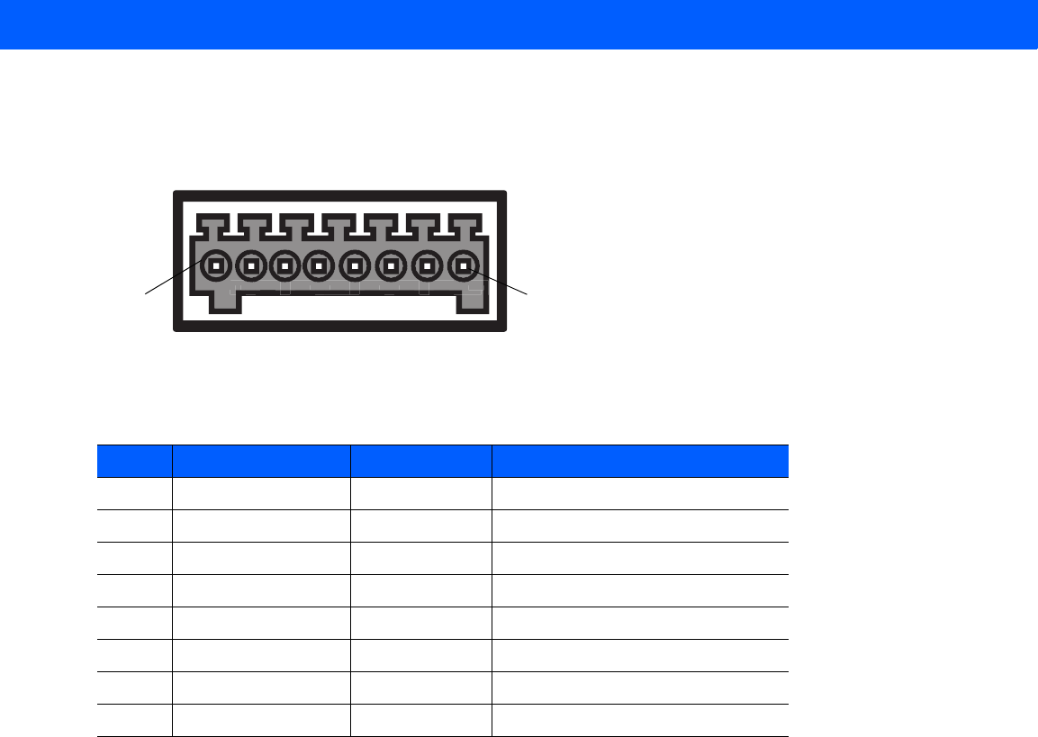
A - 6 FX7500 RFID Reader Integrator Guide
GPIO Port Connections
These plug terminal block types allow connecting and disconnecting individual wires independently. A single
connector is used for both inputs and outputs. See Table A-5 for pin descriptions.
Figure A-4
FX7500 RFID Reader GPIO Connection
Table A-5
GPIO Pin Outs
Pin # Pin Name Direction Description
1 +24V DC Power O Supplies +24V DC at up to 1 Amp
2 GP output #1 O Signal for GP output #1
3 GP output #2 O Signal for GP output #2
4 GP output #3 O Signal for GP output #3
5 GND - Ground connection
6 GP input #1 I Signal for GP input #1
7 GP input #2 I Signal for GP input #2
8 GND - Ground connection
Pin 8Pin 1

APPENDIX B LLRP AND RM API
EXTENSIONS
For information on Low Level Reader Protocol (LLRP) and Reader Management (RM) extensions for the
FX7500 reader, refer to the FX Series Reader Software Interface Control Guide.

B - 2 FX7500 RFID Reader Integrator Guide