Zebra Technologies FX7500 FX7500 RFID FIXED READER User Manual FX7500 RFID Reader Integrator Guide
Zebra Technologies Corporation FX7500 RFID FIXED READER FX7500 RFID Reader Integrator Guide
Contents
Integrator Guide

FX7500
RFID READER
INTEGRATOR GUIDE
Draft 2
Draft 2

FX7500 RFID READER
INTEGRATOR GUIDE
MN000026A04
Revision A
July 2016
Draft 2

ii FX7500 RFID Reader Integrator Guide
No part of this publication may be reproduced or used in any form, or by any electrical or mechanical means,
without permission in writing from Zebra. This includes electronic or mechanical means, such as photocopying,
recording, or information storage and retrieval systems. The material in this manual is subject to change
without notice.
The software is provided strictly on an “as is” basis. All software, including firmware, furnished to the user is on
a licensed basis. Zebra grants to the user a non-transferable and non-exclusive license to use each software
or firmware program delivered hereunder (licensed program). Except as noted below, such license may not be
assigned, sublicensed, or otherwise transferred by the user without prior written consent of Zebra. No right to
copy a licensed program in whole or in part is granted, except as permitted under copyright law. The user shall
not modify, merge, or incorporate any form or portion of a licensed program with other program material, create
a derivative work from a licensed program, or use a licensed program in a network without written permission
from Zebra. The user agrees to maintain Zebra’s copyright notice on the licensed programs delivered
hereunder, and to include the same on any authorized copies it makes, in whole or in part. The user agrees not
to decompile, disassemble, decode, or reverse engineer any licensed program delivered to the user or any
portion thereof.
Zebra reserves the right to make changes to any software or product to improve reliability, function, or design.
Zebra does not assume any product liability arising out of, or in connection with, the application or use of any
product, circuit, or application described herein.
No license is granted, either expressly or by implication, estoppel, or otherwise under any Zebra Technologies
Corporation, intellectual property rights. An implied license only exists for equipment, circuits, and subsystems
contained in Zebra products.
Zebra and the Zebra head graphic are registered trademarks of ZIH Corp. The Symbol logo is a registered
trademark of Symbol Technologies, Inc., a Zebra Technologies company.
Zebra Technologies Corporation
Lincolnshire, IL U.S.A.
http://www.zebra.com
Warranty
For the complete Zebra hardware product warranty statement, go to:
http://www.zebra.com/warranty.
Draft 2

iii
Revision History
Changes to the original manual are listed below:
Change Date Description
-01 Rev A 1/2014 Initial release
-02 Rev 2/2015 Zebra Re-Branding
-03 Rev 4/2016 Updates for SNAP; updated screen shots.
-04 Rev 7/2016 Updates:
- Changed the installing antenna separation distance to 13.4 in (34 cm).
- Changed max antenna gain exceed to + 6.6dBiL.
- Changed
Max Conducted RF Power at Antenna Input for US in table 3-1.
- Changed
Max Antenna Gain Allowed for US in table 3-1.
Draft 2

iv FX7500 RFID Reader Integrator Guide
Draft 2

TABLE OF CONTENTS
Warranty ......................................................................................................................................... ii
Revision History.............................................................................................................................. iii
About This Guide
Introduction ..................................................................................................................................... ix
Configurations........................................................................................................................... ix
Chapter Descriptions ...................................................................................................................... x
Notational Conventions................................................................................................................... xi
Related Documents and Software.................................................................................................. xi
Service Information......................................................................................................................... xii
Chapter 1: Quick Start
Introduction..................................................................................................................................... 1-1
Quick Start Demonstration.............................................................................................................. 1-1
Step 1, Setup ........................................................................................................................... 1-1
Step 2, Connecting to the Reader ............................................................................................ 1-2
Step 3, First Time / Start-Up Login .......................................................................................... 1-3
Step 4, Set Region ................................................................................................................... 1-4
Step 5, Read Tags ................................................................................................................... 1-6
Chapter 2: Getting Started
Introduction..................................................................................................................................... 2-1
RFID Technology Overview............................................................................................................ 2-1
RFID Components ................................................................................................................... 2-2
FX7500 RFID Readers .................................................................................................................. 2-3
Versions and Kits ..................................................................................................................... 2-4
FX7500 RFID Reader..................................................................................................................... 2-4
FX7500 RFID Reader Rear Panel ........................................................................................... 2-5
FX7500 RFID Readers LEDs ................................................................................................... 2-5
FX7500 RFID Reader Features ..................................................................................................... 2-7
Configuration and Upgrading ................................................................................................... 2-7
Draft 2

vi FX7500 RFID Reader Integrator Guide
Tag Management ..................................................................................................................... 2-7
Device Management ................................................................................................................ 2-7
Logging .................................................................................................................................... 2-7
Connection Options ................................................................................................................. 2-7
Chapter 3: Installation and Communication
Introduction..................................................................................................................................... 3-1
Unpacking the Reader.................................................................................................................... 3-1
Mounting and Removing the Reader.............................................................................................. 3-2
Mounting Tips .......................................................................................................................... 3-2
Mounting Using the Mounting Plate ......................................................................................... 3-2
Direct Mounting (Without the Mounting Plate) ......................................................................... 3-3
Connecting Antennas ..................................................................................................................... 3-4
Communications Connections ....................................................................................................... 3-5
Ethernet Connection ................................................................................................................ 3-5
USB Connection ...................................................................................................................... 3-6
GPIO Interface Connection ...................................................................................................... 3-9
Powering the Reader...................................................................................................................... 3-10
Powering the Reader via AC Power Supply ............................................................................ 3-10
Powering the Reader via Power-over-Ethernet (POE) ............................................................ 3-10
LED Sequences ............................................................................................................................. 3-11
System Start-up/Boot LED Sequence ...................................................................................... 3-11
PWR LED Sequence to Indicate IPv4 Status after Booting ..................................................... 3-11
Reset to Factory Defaults LED Sequence ............................................................................... 3-11
LED Sequence for Software Update Status ............................................................................. 3-11
Reading Tags ................................................................................................................................ 3-12
Chapter 4: Administrator Console
Introduction..................................................................................................................................... 4-1
Profiles ..................................................................................................................................... 4-2
Resetting the Reader ............................................................................................................... 4-2
Connecting to the Reader .............................................................................................................. 4-3
Connecting via Host Name ...................................................................................................... 4-3
Auto Discovery ......................................................................................................................... 4-4
Connecting via IP Address ....................................................................................................... 4-4
Using Zero-Configuration Networking when DHCP Server is Not Available ............................ 4-5
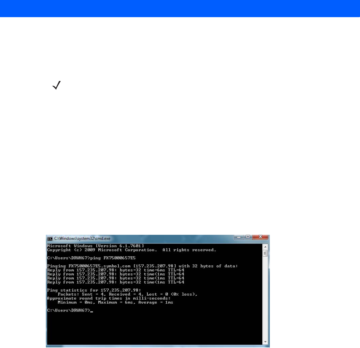
Obtaining the IP Address via Command Prompt ..................................................................... 4-5
Administrator Console Login .......................................................................................................... 4-6
First Time / Start-Up Login ....................................................................................................... 4-6
Setting the Region ................................................................................................................... 4-7
Reader Administrator Console ....................................................................................................... 4-9
Administrator Console Option Selections ................................................................................ 4-9
Status.............................................................................................................................................. 4-10
Reader Statistics............................................................................................................................. 4-11
Reader Gen2 Optional Operation Statistics ............................................................................. 4-12
NXP Custom Command Operation Statistics .......................................................................... 4-13
Event Statistics ........................................................................................................................ 4-14
Other Custom Command Operation Statistics ......................................................................... 4-15
Configure Reader .......................................................................................................................... 4-16
Draft 2

Table of Contents vii
Reader Parameters (General) ................................................................................................. 4-16
Read Points ............................................................................................................................. 4-17
Read Points - Advanced .......................................................................................................... 4-18
Configure Region ..................................................................................................................... 4-19
Certificates ............................................................................................................................... 4-20
Read Tags ..................................................................................................................................... 4-30
Communication Settings ................................................................................................................ 4-31
Configure Network Settings - Ethernet Tab ............................................................................. 4-31
Configure Network Settings - Wi-Fi Tab .................................................................................. 4-32
Configure Network Settings - Bluetooth Tab ............................................................................ 4-33
Configure LLRP Settings ......................................................................................................... 4-34
SNMP Settings ......................................................................................................................... 4-35
Wireless Settings ..................................................................................................................... 4-36
Network Services Settings ....................................................................................................... 4-37
System Time Management ............................................................................................................ 4-38
IPV6 IP Sec .................................................................................................................................... 4-39
Change Password .......................................................................................................................... 4-40
FX7500 User Accounts ............................................................................................................ 4-40
Managing User Login and Logout ............................................................................................ 4-41
GPIO............................................................................................................................................... 4-41
Applications .................................................................................................................................... 4-42
Reader Profiles ............................................................................................................................... 4-43
FIPS Support on FX7500 ......................................................................................................... 4-44
Firmware Version/Update............................................................................................................... 4-44
Firmware Update ..................................................................................................................... 4-45
Commit/Discard .............................................................................................................................. 4-45
System Log .................................................................................................................................... 4-46
Configure System Log ............................................................................................................. 4-47
Reader Diagnostics......................................................................................................................... 4-48
Shutdown........................................................................................................................................ 4-49
Chapter 5: Wi-Fi Configuration
Wireless Network Advanced Configuration..................................................................................... 5-1
Sample Configuration Files ...................................................................................................... 5-2
Preferred Configurations for Access Points ................................................................................... 5-4
AP: Zebra AP 5131 .................................................................................................................. 5-4
AP: Android Device .................................................................................................................. 5-7
iPhone ...................................................................................................................................... 5-9
Copying Files to the Reader ........................................................................................................... 5-9
Chapter 6: Application Development
Introduction..................................................................................................................................... 6-1
Reference Guides........................................................................................................................... 6-1
Draft 2

viii FX7500 RFID Reader Integrator Guide
Chapter 7: Firmware Upgrade
Introduction..................................................................................................................................... 7-1
Prerequisites................................................................................................................................... 7-1
Failsafe Update............................................................................................................................... 7-2
Update Phases ............................................................................................................................... 7-2
Updating FX7500 Reader Software ............................................................................................... 7-3
Verifying Firmware Version ...................................................................................................... 7-3
Updating Methods .................................................................................................................... 7-4
Verifying Firmware Version ...................................................................................................... 7-9
Chapter 8: Troubleshooting
Appendix A: Technical Specifications
FX7500 Kits .................................................................................................................................... A-1
KT-FX75004US-01 4-Port US Reader Kit ................................................................................ A-1
KT-FX75002US-01 2-Port US Reader Kit ................................................................................ A-1
KT-FX75004WR-01 4-Port Global Reader Kit ......................................................................... A-1
KT-FX75002WR-01 2-Port Global Reader Kit ......................................................................... A-2
Technical Specifications ................................................................................................................. A-2
Cable Pinouts ................................................................................................................................. A-4
10/100bT Ethernet / POE Connector ....................................................................................... A-4
USB Client Connector .............................................................................................................. A-5
USB Host Connector ................................................................................................................ A-5
GPIO Port Connections ........................................................................................................... A-6
Appendix B: Static IP Configuration
Introduction..................................................................................................................................... B-1
Reader IP Address or Host Name is Known -
Set the Static IP Using the Web Console................................................................................. B-1
Reader IP is Not Known (DHCP Network Not Available) -
Set the Static IP Using the Web Console ................................................................................. B-3
Appendix C: RF Air Link Configuration
Introduction..................................................................................................................................... C-1
Radio Modes................................................................................................................................... C-1
Appendix D: Connecting Wi-Fi and Bluetooth Dongles
Introduction..................................................................................................................................... D-1
Connecting to a Wireless Network Using a Wi-Fi Dongle............................................................... D-1
Connecting to a Peer Device over Bluetooth Using a Bluetooth Dongle ....................................... D-5
Draft 2

Table of Contents ix
Appendix E: Copying Files To and From the Reader
Introduction ..................................................................................................................................... E-1
SCP................................................................................................................................................. E-1
FTP ................................................................................................................................................. E-1
FTPS............................................................................................................................................... E-2
Appendix F: Data Protection
Introduction..................................................................................................................................... F-1
Index
Draft 2

x FX7500 RFID Reader Integrator Guide
Draft 2

ABOUT THIS GUIDE
Introduction
This Integrator Guide provides information about installing, configuring, and using the FX7500 RFID readers and is
intended for use by professional installers and system integrators. The FX7500 readers provide real time,
seamless tag processing for EPC Class1 Gen2 compliant tags.
Configurations
This guide includes the following FX7500 RFID reader configurations:
•
FX7500-42320A50-US: 4-Port FCC
•
FX7500-22320A50-US: 2-Port FCC
•
FX7500-42325A50-WR: 4-Port Worldwide
•
FX7500-22325A50-WR: 2-Port Worldwide
NOTE Screens and windows pictured in this guide are samples and may differ from actual screens.
Draft 2

x FX7500 RFID Reader Integrator Guide
Chapter Descriptions
Topics covered in this guide are as follows:
•
Chapter 1, Quick Start provides a Quick Start tag reading demonstration.
•
Chapter 2, Getting Started provides an overview of RFID technology/components and a description of
the FX7500 reader and features.
•
Chapter 3, Installation and Communication provides information on installing and setting up the FX7500
readers.
•
Chapter 4, Administrator Console describes how to connect to the reader and how to use the web-based
Administrator Console to configure and manage FX7500 readers.
•
Chapter 5, Wi-Fi Configuration details wireless network advanced configuration and preferred
configurations for access points.
•
Chapter 6, Application Development provides information on developing applications for the FX7500,
and includes references to the appropriate guides.
•
Chapter 7, Firmware Upgrade provides reader firmware upgrade information on using the web-based
Administrator Console and an FTP or FTPS server running a host computer.
•
Chapter 8, Troubleshooting describes FX7500 readers troubleshooting procedures.
•
Appendix A, Technical Specifications includes the technical specifications for the reader.
•
Appendix B, Static IP Configuration describes three methods of setting the static IP address on an
FX7500 RFID Reader.
•
Appendix C, RF Air Link Configuration describes how to select air link configuration from a set of
available air link profiles.
•
Appendix D, Connecting Wi-Fi and Bluetooth Dongles describes how to connect to a wireless network
using a USB Wi-Fi dongle on the FX7500, and how to connect to a peer device over Bluetooth using a
USB Bluetooth dongle.
•
Appendix E, Copying Files To and From the Reader describes the SCP, FTP, and FTPS protocols for
copying files.
•
Appendix F, Data Protection describes how the FX7500 protects RFID data in transition.
Draft 2

About This Guide xi
Notational Conventions
The following conventions are used in this document:
•
“RFID reader” or “reader” refers to the Zebra FX7500 RFID readers.
•
Italics are used to highlight the following:
•Chapters and sections in this and related documents
•Dialog box, window, links, software names, and screen names
•Drop-down list, columns and list box names
•Check box and radio button names
•Icons on a screen
•
Bold text is used to highlight the following:
•Dialog box, window and screen names
•Drop-down list and list box names
•Check box and radio button names
•Icons on a screen
•Key names on a keypad
•Button names on a screen
•
Bullets (•) indicate:
•Action items
•Lists of alternatives
•Lists of required steps that are not necessarily sequential.
•
Sequential lists (e.g., those that describe step-by-step procedures) appear as numbered lists.
Related Documents and Software
The following documents provide more information about the reader.
•
FX7500 RFID Reader Quick Start Guide, p/n MN000070A01
•
FX Series Reader Software Interface Control Guide, p/n 72E-131718-xx. Describes Low Level Reader
Protocol (LLRP) and Reader Management (RM) extensions for the FX7500 reader.
•
RFID Demo Applications User Guide, p/n 72E-160038-01. Provides instructions for using sample
applications which demonstrate how to use Zebra RFID readers.
•
FX7500 Embedded SDK Installation Guide. Provides instructions for installing the embedded SDK for C
and Java.
•
FX7500 Embedded SDK Sample Application Guide. Explains how to use the embedded sample
application with an integrated development environment.
•
FX7500 Embedded SDK Programmers Guide. Provides instructions for creating new embedded
applications.
•
RFID3 API
•
EPCglobal Low Level Reader Protocol (LLRP) Standard
For the latest version of these guides and software, visit: http://www.zebra.com/support.
Draft 2

xii FX7500 RFID Reader Integrator Guide
Service Information
If you have a problem using the equipment, contact your facility's technical or systems support. If there is a
problem with the equipment, they will contact the Zebra Global Customer Support Center at:
http://www.zebra.com/support.
When contacting Zebra support, please have the following information available:
•
Serial number of the unit
•
Model number or product name
•
Software type and version number.
Zebra responds to calls by e-mail, telephone or fax within the time limits set forth in support agreements.
If your problem cannot be solved by Zebra support, you may need to return your equipment for servicing and
will be given specific directions. Zebra is not responsible for any damages incurred during shipment if the
approved shipping container is not used. Shipping the units improperly can possibly void the warranty.
If you purchased your business product from a Zebra business partner, contact that business partner for
support.
Draft 2

CHAPTER 1 QUICK START
Introduction
This chapter provides a Quick Start setup demonstration.
Quick Start Demonstration
The Quick Start demonstration offers a simple, temporary way to quickly set up the reader and read tags. The
demonstration includes:
•
Step 1, Setup on page 1-1
•
Step 2, Connecting to the Reader on page 1-2
•
Step 3, First Time / Start-Up Login on page 1-3
•
Step 4, Set Region on page 1-4
•
Step 5, Read Tags on page 1-6
Step 1, Setup
For information on complete component kits available from Zebra, see Appendix A, Technical Specifications.
1. Unpack the reader. See Unpacking the Reader on page 3-1.
2. Set up the reader and tags on a desktop.
3. Connect the antenna to antenna Port 1. See Figure 1-1.
4. Connect the Ethernet cable to the Ethernet port. See Figure 1-1.
Connecting the reader to a subnet that supports DHCP is recommended. This Quick Start procedure is not
guaranteed to work if DHCP is disabled in the reader and if the reader is connected directly to a PC.
5. Connect the AC power supply to a power outlet and connect to the power port. See Figure 1-1.
NOTE This step is not required for networks supporting Power-over-Ethernet (POE).
Draft 2
1 - 2 FX7500 RFID Reader Integrator Guide
6. Wait for the green power LED to stay lit. See System Start-up/Boot LED Sequence on page 3-11 for
boot-up details.
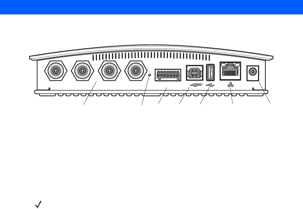
Figure 1-1
FX7500 RFID Reader Rear Panel Connections
Step 2, Connecting to the Reader
To connect via host name:
1. Open a browser. Recommended browsers are IE10 (disabling Compatibility View is recommended),
Chrome v29, and FireFox 24.
2. Enter the host name, printed on the host name label on the reader, in the browser
(e.g., http://fx7500cd3b0d) and press Enter. The User Login window appears and the reader is ready.
To connect using the USB port for network connection, see Wireless Intrusion Protection System. The default
USB RNDIS IP address for the reader is 169.254.10.1
Port 1 Port 2 Port 3 Port 4 GPIO 24 VDC
Antenna Ports (Four Ports, Reverse TNC) USB-B
Client Power
GPIO 10/100BaseT
Ethernet (with POE)
Reset USB-A
Host
NOTE Connect the reader to a network that supports host name registration and lookup to ensure the network
can access the reader using the host name. For instance, some networks can register hostnames
through DHCP. When first connecting to the reader, it is recommended to keep DHCP enabled in both the
PC and in the reader, although it is not guaranteed that hostname will work all the time. Use the host
name printed on the reader label, or construct it using the reader MAC address on the bottom of the
reader. The host name is a string with the prefix FX7500, followed by the last three MAC address octets.
For example, for a MAC address of 00:15:70:CD:3B:0D, use the prefix FX7500, followed by CD, 3B, and
0D, to create the host name FX7500CD3B0D. Enter http://FX7500CD3B0D in the browser address bar
to access the reader.
Draft 2
Quick Start 1 - 3
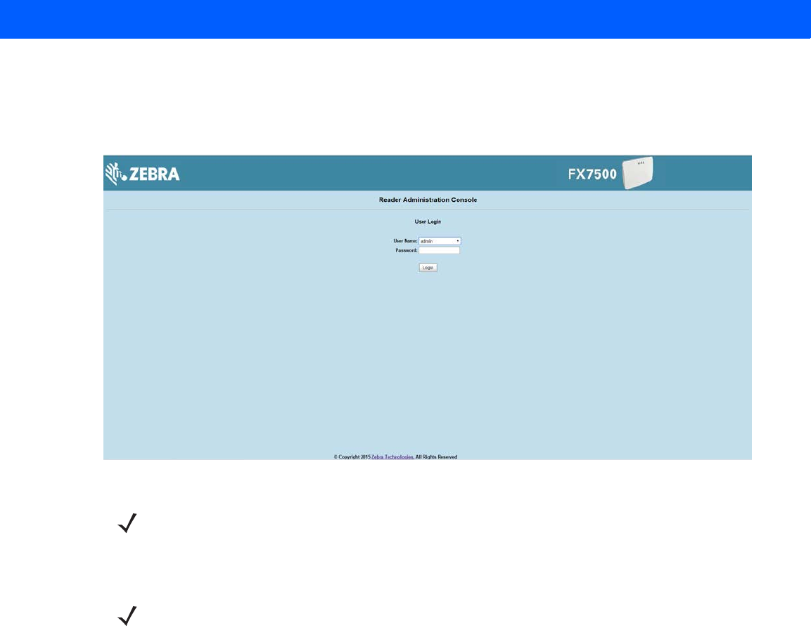
Step 3, First Time / Start-Up Login
When starting the reader for the first time:
1. In the User Login window, enter admin in the User Name: field and enter change in the Password: field.
Figure 1-2
User Login Window
2. Click Login. The Region Configuration window appears.
NOTE If you forget the user ID and/or password, see Reset to Factory Defaults LED Sequence on page 3-11 to
reset the reader to factory defaults, and then select admin for the user name and enter change in the
password field to regain access.
NOTE The Region Configuration window does not appear for US reader configurations. For these models, the
Administrator Console main window appears.
See
Figure 4-1 on page 4-2
.
Draft 2
1 - 4 FX7500 RFID Reader Integrator Guide
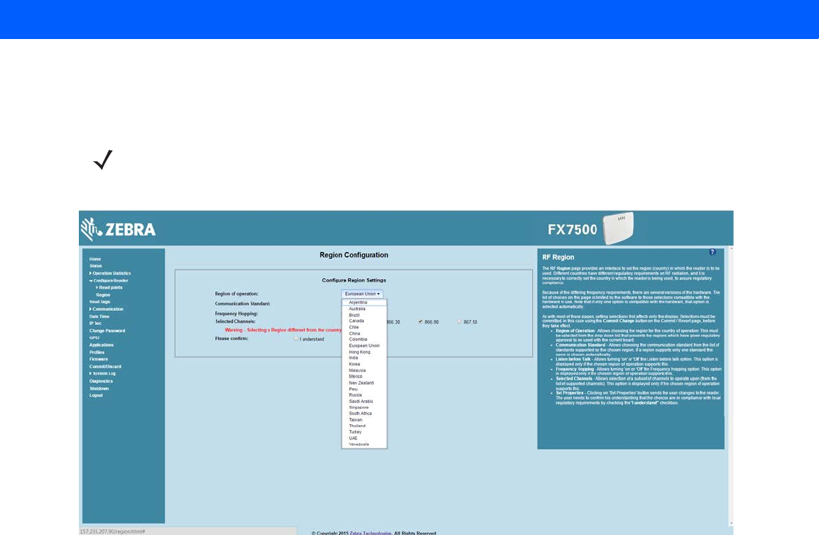
Step 4, Set Region
Set the region of operation. Setting the unit to a different region is illegal.
1. In the Configure Region Settings window, select the region from the drop-down menu.
Figure 1-3
Selecting the Region
2. Select the Communication Standard, if applicable.
3. Select Frequency Wireless IPSy Hopping, if applicable.
4. Select the appropriate channel(s), if applicable.
5. Select the I understand check box.
NOTE Region configuration is not available for readers configured to operate in the United States region (under
FCC rules). In this case, skip this step.
Draft 2

Quick Start 1 - 5
6. Select Set Properties to complete the region selection. The Operation Successful window appears.
Figure 1-4
Region Configuration, Operation Successful Window
7. Select Commit/Discard.
Figure 1-5
Commit/Discard Window
8. Click Commit to save the new region configuration and apply these changes to the reader configuration
file, or click Discard to discard the region configuration changes. When the commit completes, the Commit
Successful window appears.
Draft 2
1 - 6 FX7500 RFID Reader Integrator Guide
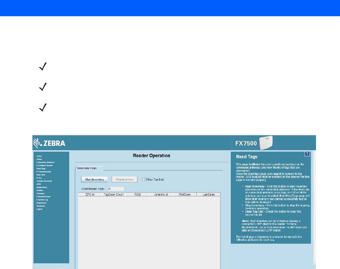
Step 5, Read Tags
Select Read Tags to view the Reader Operation window.
Figure 1-6
Read Tags Window
•
Click Start Inventory to initiate an on-demand scan on the connected antennas that are enabled.
•
Click Stop Inventory to stop the inventory operation.
•
Select the Clear Tag List check box to clear the current tag list.
The list of tags appears in a table with the following attributes for each tag:
•
EPC Id: Unique tag EPC ID.
•
TagSeen Count: Number of times the tag is identified on the specific antenna.
•
RSSI: Received Signal Strength Indication.
•
Antenna Id: Antenna ID on which the tag is seen.
•
FirstSeen time stamp: UTC time (in microseconds) when the tag was first seen.
•
LastSeen time stamp: UTC time (in microseconds) when the tag was last seen.
NOTE Enable Java JRE support on the browser for this page to function properly.
NOTE For security reasons browsers may block the Read Tags page. Look for a pop window that can be hidden
behind the browser or at the bottom of the screen (the taskbar in Windows) and allow the applet to run.
NOTE With older browsers, when upgrading/downgrading the FX7500, close the browser and re-open it to clear
the old version of files cached. If the java cache for applets is on, clear the cached applet before starting
the browser to use the Read Tags page.
Draft 2

CHAPTER 2 GETTING STARTED
Introduction
This chapter provides an overview of RFID technology and components, and describes the FX7500 reader and
its features.
RFID Technology Overview
RFID (Radio Frequency Identification) is an advanced automatic identification (Auto ID) technology that uses
radio frequency signals to identify tagged items. An RFID tag contains a circuit that can store data. This data
may be pre-encoded or can be encoded in the field. The tags come in a variety of shapes and sizes.
A typical RFID system consists of transponders (called tags), readers, and antennas. To read a tag the reader
sends out radio frequency waves (using attached antennas). This RF field powers and charges the tags, which
are tuned to receive radio waves. The tags use this power to modulate the carrier signal. The reader interprets
the modulated signal and converts the data to a format for computer storage. The computer application
translates the data into an understandable format.
Figure 2-1
RFID System Elements
Reader and Antenna
Host Computer
Physical/Network
Connection
RF Wave and
Response
Tags
Draft 2

2 - 2 FX7500 RFID Reader Integrator Guide
RFID Components
Zebra RFID offer low cost, long read range, and a high read rate. These features provide real time, end-to-end
visibility of products and assets in the factory, distribution center, retail outlet, or other facility. A typical Zebra
RFID system consists of the following components:
•
Silicon based RFID tags that attach to retail products, vehicles, trailers, containers, pallets, boxes, etc.
•
Different antenna types to support applications such as dock door (area antennas) and conveyor.
•
Readers power and communicate with the tags for data capture and provide host connectivity for data
migration.
Tags
Tags contain embedded chips that store unique information. Available in various shapes and sizes, tags, often
called transponders, receive and respond to data requests. Tags require power to send data, and are available
with two power options:
•
Active Tags: typically powered by light-weight batteries and have limited life.
•
Passive Tags: the RFID reader generates an RF field that powers the tag. Passive tags are much lighter,
less expensive, and have a much longer life than active tags.
Antennas
Antennas transmit and receive radio frequency signals. A read point is the RF range of an antenna.
Readers
Readers communicate with the tags and can transfer the data to a host computer. Readers also provide
features such as filtering and tag writing. FX7500 readers read Gen2 (dense reader mode) RFID tags.
Draft 2
Getting Started 2 - 3
FX7500 RFID Readers
The Zebra FX7500 RFID readers are intelligent, C1G2 UHF RFID readers with RFID read performance that
provides real-time, seamless EPC-compliant tags processing. FX7500 RFID readers are designed for indoor
inventory management and asset tracking applications in large scale deployments. The readers can host
third-party customer-driven embedded applications.
FX7500 RFID readers are based on Zebra's strategic FX7500 reader platform and are easy to use, deploy, and
manage. The readers offer a variety of options for connecting to corporate networks using Ethernet or USB
connections. Features include:
•
ISO 18000-6C standard (EPC Class 1 Gen 2)
•
Dense reader mode capability
•
Enterprise-class performance
•
Application-specific setup for ease of installation
•
Power over Ethernet (POE) to eliminate the need for a power drop
•
SSL/SSH based security for secure data transmission
•
Linux operating system
•
Support for custom or third-party applications
•
Feature set for event and tag management
•
Support for NXP custom commands over LLRP
•
Radio mode support via LLRP v1.0.1
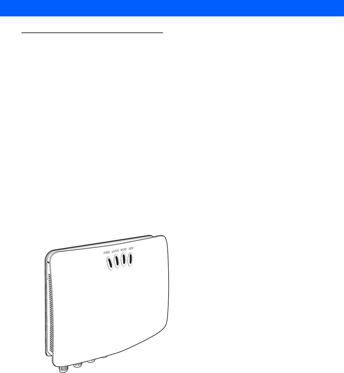
Figure 2-2
FX RFID Reader
The reader provides a wide range of features that enable implementation of complete, high-performance,
intelligent RFID solutions.
FX7500 RFID reader configurations include either two or four
monostatic
antenna ports. The monostatic ports
are used only with monostatic antennas.
Draft 2
2 - 4 FX7500 RFID Reader Integrator Guide
Versions and Kits
FX7500 RFID readers are available in a 2-port or 4-port version, individually (reader and mounting bracket) or
in a kit that includes the reader, mounting bracket, an antenna, and a power supply. For detailed kit information,
see FX7500 Kits on page A-1.
FX7500 RFID Reader
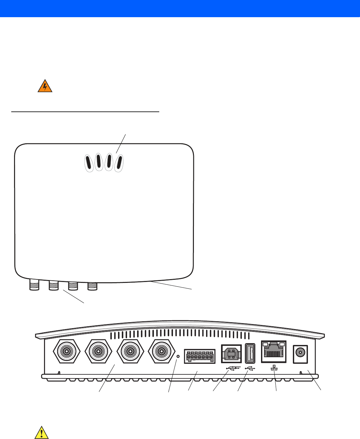
Figure 2-3
FX7500 RFID Reader
Figure 2-4
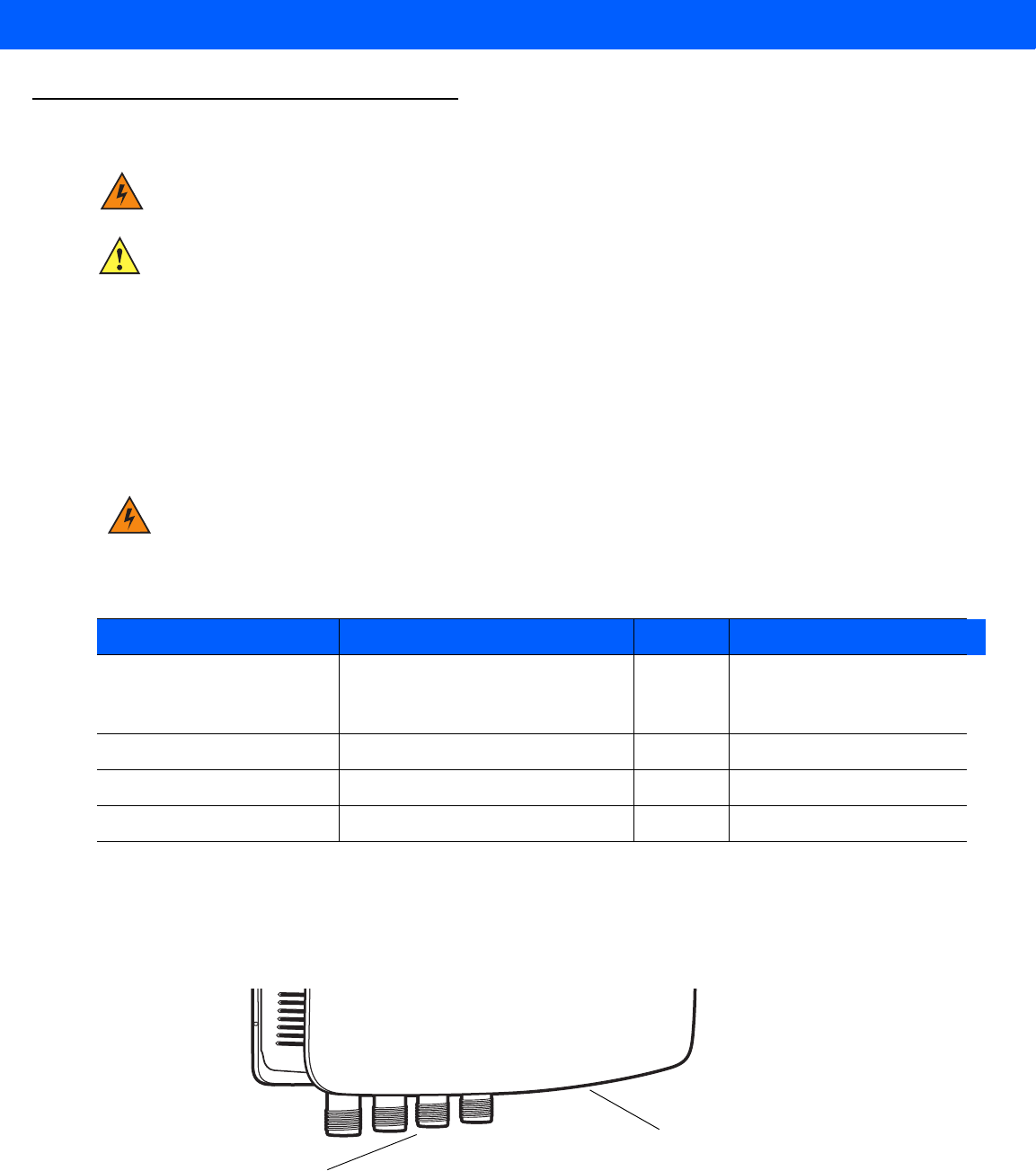
FX7500 RFID Reader Rear Panel Connections
WARNING!For Mounting in Environmental Air Handling Space (EAHS): Do not install the Mounting
Bracket, Antenna, Cables, PSU, and PoE (Power Injector) in the EAHS unless they are suitable
for use in EAHS per UL 2043.
PWR ACTV STAT APP
Antenna Ports (Reverse TNC)
LEDs
Rear Panel
Port 1 Port 2 Port 3 Port 4 GPIO 24 VDC
Antenna Ports (Four Ports, Reverse TNC) USB-B
Client Power
GPIO 10/100BaseT
Ethernet (with POE)
Reset USB-A
Host
CAUTION Use only parts provided with the FX7500 RFID readers, or Zebra approved/recommended parts.
Substituting other cables or parts can degrade system performance, damage the reader, and/or void
the warranty.
Draft 2

Getting Started 2 - 5
FX7500 RFID Reader Rear Panel
FX7500 RFID Readers LEDs
The reader LEDs indicate reader status as described in Table 2-2. For the LED boot up sequence see System
Start-up/Boot LED Sequence on page 3-11.
Figure 2-5
FX7500 RFID Readers LEDs
Table 2-1
Rear Panel Descriptions
Port Description
Antenna Ports
(Reverse TNC) Two port version: Connect up to two antennas.
Four port version: Connect up to four antennas.
See
Table A-1 on page A-2
for the maximum antenna gains and RF output powers for both
US/Canada and EU. See
Connecting Antennas on page 3-4
for connection information.
Reset To reset the reader insert a paper clip into the reset hole, press and hold the reset button for
not more than 2 seconds. This resets the reader, but retains the user ID and password.
GPIO See
GPIO Interface Connection on page 3-9
for more information.
USB Client The USB client port supports (by default) a network mode of operation. This enables a
secondary network interface as a virtual adapter over USB.
Advanced users can create a custom communication protocol on the USB port.
See
USB
Connection on page 3-6
for connection information.
USB Host Use the USB host port to connect USB devices such as WiFi / Bluetooth over USB dongles
and flash memory drives.
10/100BaseT
Ethernet Insert a standard RJ45 Ethernet cable to connect to an Ethernet network with or without
POE capability, or to a local computer. See
Ethernet Connection on page 3-5
for
connection information.
Power DC connector connects to a Zebra approved power supply AC adapter (varies depending
on the country). Maximum power 24 VDC, 1.2 A. See
Powering the Reader on page 3-10
for connection information.
PWR ACTV STAT APP
Draft 2

2 - 6 FX7500 RFID Reader Integrator Guide
Table 2-2
LED Indications
LED Function Color/Status Description
PWR Power Off
Amber Solid
Red Flashing
Amber Solid
Green Solid
Reader is powered off
Booting
Firmware upgrade
Application initialization after booting
Reader is powered on and operational
ACTV Activity Off
Amber Flashing
Green Flashing
No RF operations
On for 500 mSec indicates another tag operation
On for 500 mSec indicates a tag is inventoried or read
STAT Status Off
Red Solid
Red Flashing
Green Flashing
No errors or GPIO events
Firmware update failure
On for 500 mSec indicates an error in RF operation
On for 500 mSec indicates a GPI event
APP Application Green/Red/Amber Controlled through RM
Draft 2

Getting Started 2 - 7
FX7500 RFID Reader Features
Configuration and Upgrading
Use the Administrator Console to reconfigure the reader. See Chapter 4, Administrator Console. The reader
can also accept new firmware and configuration updates.
Tag Management
The Administrator Console provides the Read tags feature. See Read Tags on page 4-30. Use client
applications based on Zebra EMDK (Enterprise Mobility Development Kit) such as Power Session, or LLRP
(EPCGlobal Low Level Reader Protocol) for additional tag management operations such as Write, Lock,
Filtering, Event Management and Kill.
Device Management
Quick Backup and Recovery
Use a web browser to back up and restore reader configuration by downloading the configuration XML file. Use
the Administrator Console to download the file to the reader.
SNMP Integration
The reader can send real time notification of specific events and failures to an SNMP server.
Logging
The reader keeps a log of all system-related activities for security and troubleshooting. The log includes
time-stamped system activities such as login attempts and hardware failures. Use the log to pinpoint problems,
to facilitate quick resolution, and to identify administrators who may require additional training to prevent future
problems. See System Log on page 4-46.
Connection Options
The FX7500 provides flexibility for connecting to networks through an Ethernet connection or the USB client
port. The reader’s primary network interface is Ethernet. The Ethernet interface accesses each reader from
anywhere on the network using the unique host name or IP address.
Additionally, the USB client port supports (by default) a Network mode of operation. This enables a secondary
network interface as a virtual adapter over USB. The interfaces co-exist and if the Ethernet connection fails,
the application can switch to USB using a specific IP and can control the reader.
See Communications Connections on page 3-5. To use the USB port for network connection, see Wireless
Intrusion Protection Systeml Wireless IPS.
Draft 2

2 - 8 FX7500 RFID Reader Integrator Guide
Draft 2

CHAPTER 3 INSTALLATION AND
COMMUNICATION
Introduction
This chapter includes the following FX7500 RFID reader installation and communication procedures:
•
Unpacking the Reader on page 3-1
•
Mounting and Removing the Reader on page 3-2
•Mounting Tips on page 3-2
•Mounting Using the Mounting Plate on page 3-2
•Direct Mounting (Without the Mounting Plate) on page 3-3
•
Connecting Antennas on page 3-4
•
Communications Connections on page 3-5
•Ethernet Connection on page 3-5
•USB Connection on page 3-6
•GPIO Interface Connection on page 3-9
•
Powering the Reader on page 3-10
•Powering the Reader via AC Power Supply on page 3-10
•Powering the Reader via Power-over-Ethernet (POE) on page 3-10
•
System Start-up/Boot LED Sequence on page 3-11
Unpacking the Reader
Remove the reader from the shipping container and inspect it for damage. Keep the shipping container, it is the
approved shipping container and should be used if the reader needs to be returned for servicing.
CAUTION FX7500 RFID readers must be professionally installed.
WARNING!For Mounting in Environmental Air Handling Space (EAHS): Any cables used to interconnect
to other equipment must be suitable for use in EAHS as per UL2043.
Draft 2
3 - 2 FX7500 RFID Reader Integrator Guide
Mounting and Removing the Reader
Mounting Tips
Mount the reader in any orientation. Consider the following before selecting a location for the FX7500 reader:
•
Mount the reader indoors, in operating range and out of direct sunlight, high moisture, and/or extreme
temperatures.
•
Mount the reader in an area free from electromagnetic interference. Sources of interference include
generators, pumps, converters, non-interruptible power supplies, AC switching relays, light dimmers, and
computer CRT terminals.
•
Mount the reader within 15 feet of the antennas.
•
Ensure that power can reach the reader.
•
The recommended minimum horizontal mounting surface width is 7 1/2 inches. However, the unit can
mount on surfaces as narrow as 6 inches (in locations where unit overhang is not an issue). For vertical
mounting the unit can mount on a surface as small as 6 inches by 6 inches.
•
Mount the reader onto a permanent fixture, such as a wall or a shelf, where it is not disturbed, bumped,
or damaged. The recommended minimum clearance on all sides of the reader is five inches.
•
Use a level for precise vertical or horizontal mounting.
Mounting Using the Mounting Plate
1. Position the mounting plate on a flat surface (wall or shelf). Position the release tab on the top. See Figure
3-1.
2. Mark the hole locations using the mounting plate as a guide. See Figure 3-1. Remove the mounting plate
and drill holes (appropriate for the surface material) at the marked locations.
WARNING!When installing the antenna ensure a minimum separation distance of 13.4 in (34 cm)
between the antennas and all persons.
WARNING!For Mounting in Environmental Air Handling Space (EAHS): Do not install the Mounting
Bracket in the EAHS.
NOTE For wood surfaces, drill two 1/8" diameter by 7/8" deep holes. For drywall/masonry surfaces, drill two
3/16" diameter by 7/8" deep (min) holes and install using the provided anchors.
Draft 2
Installation and Communication 3 - 3
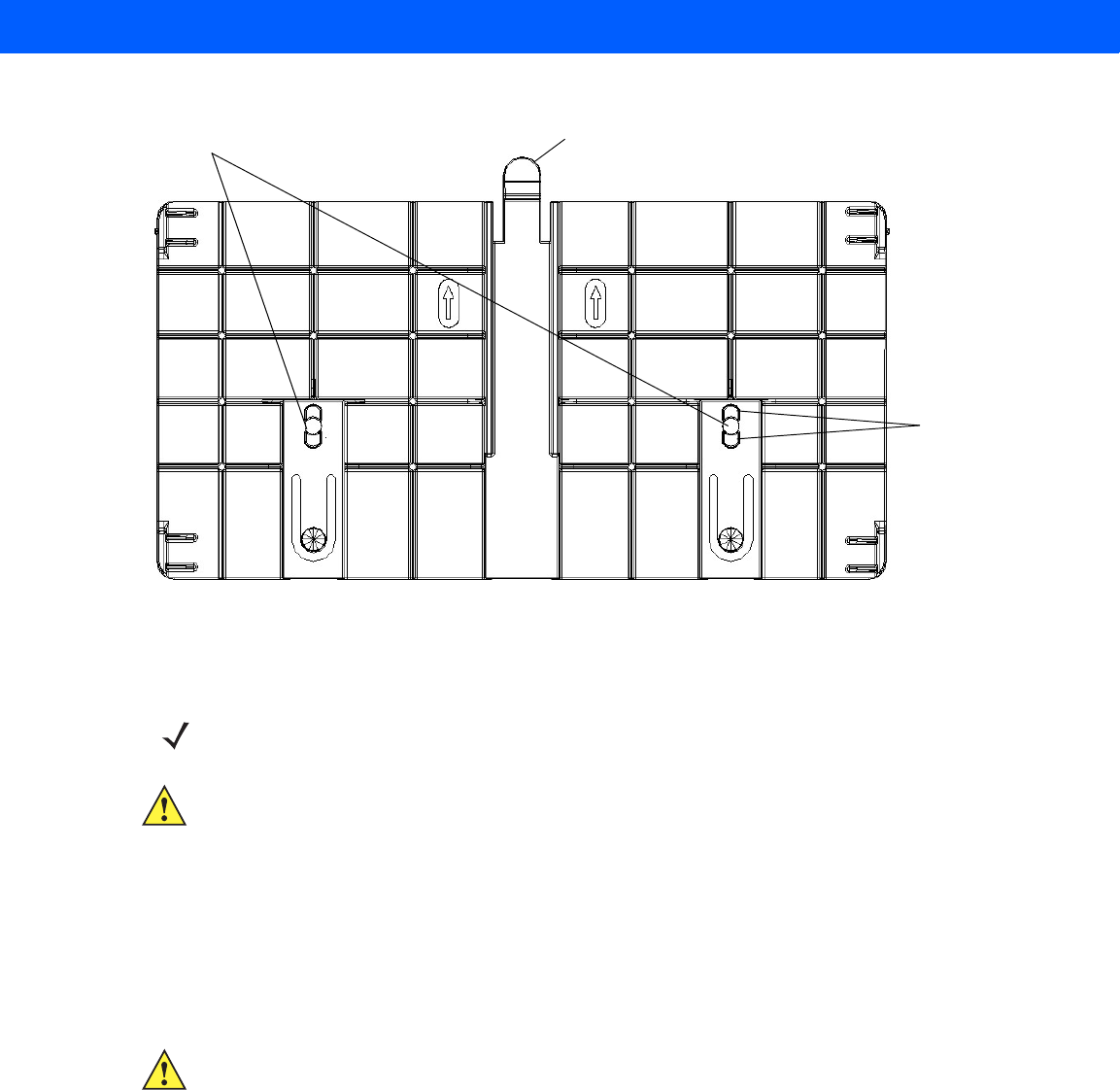
Figure 3-1
Mounting Plate, Front
3. Reposition the mounting plate over the mounting holes and secure using the supplied fasteners (as
appropriate for the surface material).
4. Position the reader by aligning the markers on the metal base plate and the wall bracket, with the key-slot
holes over the mounting screws. Gently slide the reader down to lock into place.
5. To remove the reader, press the release tab and slide the reader up while gently pulling out.
Direct Mounting (Without the Mounting Plate)
To mount the unit without using the mounting bracket:
1. Use the mounting bracket as a template to locate the holes, or locate and mark the holes on 4 3/16”
centers, +/- 1/32”.
2. For wood surfaces, drill two 1/8" diameter by 7/8" deep holes on 4.192" centers. For drywall/masonry
surfaces, drill two 3/16" diameter by 7/8" deep (min) holes on 4.192" centers and install using the provided
anchors.
3. Position the reader with the key-slot holes over the mounting screws and gently slide the reader down to
lock into place.
4. Adjust the screw head height to assure a snug fit. Or if the screws are accessible from the back, use
machine screws with a lock washer/nut and tighten the nut (from the back) to secure the reader.
Screw Head Stops
(4 typical)
Release Tab
Mounting Holes
NOTE Mount the reader with the cable connections up or down, depending on the installation requirements.
CAUTION Use a hand screw driver to install the mounting plate (do not use a power driver). Do not use
excessive torque, and tighten the screws so that they are just snug on the screw head stops (see
Figure 3-1). If the reader does not engage the mounting plate, loosen the screw(s) 1/8 to 1/4 turn and
try again.
CAUTION Not using the mounting plate can affect read performance at elevated temperatures. Also, if not using
the mounting plate, secure the reader to prevent it from coming off of the mounting screws.
Draft 2
3 - 4 FX7500 RFID Reader Integrator Guide
Connecting Antennas
To connect the antennas to the reader (see Figure 3-2):
1. For each antenna, attach the antenna reverse TNC connector to an antenna port.
2. Secure the cable using wire ties. Do not bend the cable.
Figure 3-2
FX7500 RFID Reader Antenna Connection
WARNING!When installing the antenna ensure a minimum separation distance of 13.4 in (34 cm) between
the antenna and all persons.
CAUTION Power off the reader before connecting antennas. See Powering the Reader on page 3-10. Never
disconnect the antennas while the reader is powered on or reading tags. This can damage the reader.
Do not turn on the antenna ports from a host when the antennas are not connected.
Maximum antenna gain (including any cable loss) cannot exceed + 6.6dBiL. See Table 3-1 for
corresponding maximum conducted RF power at antenna input.
When mounting the antennas outside the building, connect the screen of the coaxial cable to earth
(ground) at the entrance to the building. Perform this in accordance with applicable national electrical
installation codes. In the U.S., this is required by Section 820.93 of the National Electrical Code,
ANSI/NFPA 70.
WARNING!For Mounting in Environmental Air Handling Space (EAHS): Do not install Antennas and
Antenna Cables in the EAHS unless they are suitable for use in EAHS as per UL 2043.
Table 3-1
Antenna Gain and Radiated Power
FX7500 US and Canada EU
Max Conducted RF Power
at Antenna Input + 30.0dBm with + 6.0dBiL max gain
antenna or + 29.36dBm with +
6.6dBiL max gain antenna
+29.2dBm
Max Antenna Gain Allowed + 6.6dBiL + 5.5dBiL
Max Radiated Power Allowed 4W EIRP 2W ERP
Antenna Type Circularly Polarized Plate N/A
Antenna Ports (Reverse TNC)
Rear Panel
Taiwan
+ 6.6dBiL
4W EIRP
Circularly Polarized Plate
+ 29.79dBm with + 6.0dBiL max
gain antenna or + 29.36dBm
with + 6.6dBiL max gain antenna
Draft 2

Installation and Communication 3 - 5
Communications Connections
Use a standard Ethernet connection, a standard POE, or POE + Ethernet connection to connect the FX7500
reader to a host or network.
Ethernet Connection
The reader communicates with the host using an Ethernet connection (10/100Base-T Ethernet cable). This
connection allows access to the Administrator Console, used to change reader settings and control the reader.
With a wired Ethernet connection (10/100Base-T cable), power the FX7500 reader using either the reader
Zebra AC power supply, or by Power-Over-Ethernet through the Ethernet cable.
Ethernet: Power through AC Outlet
The FX7500 reader communicates to the host through a 10/100Base-T Ethernet cable and receives power
through a Zebra AC power supply.
1. Route the Ethernet cable.
2. Route the power cable.
3. Terminate the Ethernet cable according to Table A-2 on page A-4.
4. Connect the Ethernet cable to the LAN port on the FX7500 reader. See Figure 2-4 on page 2-4.
5. Connect the other end of the Ethernet cable to the host system LAN port.
6. Connect the Zebra AC power supply to a wall outlet.
7. Insert the power supply barrel connector into the FX7500 reader power port. See Figure 2-4 on page 2-4.
8. Verify that the unit booted properly and is operational. See System Start-up/Boot LED Sequence on page
3-11.
9. On a networked computer, open an internet browser and connect to the reader. See Connecting to the
Reader on page 4-3.
10. Log in to the Administrator Console. See Administrator Console Login on page 4-6.
Ethernet: Power through Standard POE or POE+
The POE installation option allows the FX7500 reader to communicate and receive power on the same
10/100Base-T Ethernet cable.
1. Insert the POE Ethernet connector on the RJ45 Ethernet cable into the reader 10/100BaseT Ethernet port.
See Figure 2-4 on page 2-4.
2. Connect the other end of the cable to an Ethernet network with POE capability.
3. Verify that the reader booted properly and is operational. See System Start-up/Boot LED Sequence on
page 3-11.
4. On a networked computer, open an internet browser and connect to the reader. See Connecting to the
Reader on page 4-3.
5. Log in to the Administrator Console. See Administrator Console Login on page 4-6.
CAUTION Do not connect to PoE networks outside the building.
Draft 2

3 - 6 FX7500 RFID Reader Integrator Guide
To connect to a network that is not POE capable:
1. Terminate the Ethernet cable according to Table A-2 on page A-4.
2. Connect the Ethernet cable to the FX7500 reader 10/100BaseT Ethernet port. See Figure 2-4 on page 2-4.
3. Connect the other end of the Ethernet cable to a POE power injector.
4. Connect a patch cable from the POE power injector to the host system LAN port.
5. Verify that the unit booted properly and is operational. See System Start-up/Boot LED Sequence on page
3-11.
6. On a networked computer, open an internet browser and connect to the reader. See Connecting to the
Reader on page 4-3.
7. Log in to the Administrator Console. See Administrator Console Login on page 4-6.
USB Connection
The USB client port supports (by default) a Network mode of operation. This enables a secondary network
interface as a virtual adapter over USB. The interfaces co-exist and if the Ethernet connection fails, the
application can switch to USB using a specific IP and can control the reader. To use the USB port for network
connection, install the USB RNDIS Driver on the Windows XP PC or follow the instructions to install the
Microsoft RNDIS driver for Windows 7 below.
To connect the FX7500 to the host PC, insert a USB cable into the USB client port on the reader. See Figure
2-4 on page 2-4. Connect the other end of the cable to a USB port on the host PC.
Zebra USB RNDIS Driver
To use the USB port for network connection, install the Zebra USB Remote Network Device (RNDIS) driver
and enable the driver on the FX7500. The Zebra RNDIS driver supports 32-bit version operating systems
Windows XP, Windows Vista, Windows 7, and Windows Server 2008. For Windows 7 32-bit and 64-bit
systems, it is recommend to use Microsoft RNDIS driver (see Microsoft RNDIS Driver for Windows 7 on page
3-7).
To install the RNDIS driver on the host.
1. Download the installer file Zebra RNDIS.msi from http://www.zebra.com/support to the host PC.
2. Select this file on the host PC to install the host side drivers for using the USB Remote Network Device
Interface on the FX7500.
3. Connect a USB cable between the host and the reader. The Welcome to the Found New Hardware Wizard
screen appears.
4. Select the No, not this time radio button and click Next.
5. Select the default option Install Software Automatically (Recommended).
6. In the Hardware Installation pop-up window, select Continue Anyway.
7. Select Finish to complete the installation. This assigns the host an auto-configured IP address. The
network is now ready to use and the reader’s IP address is fixed to 169.254.10.1.
Draft 2
Installation and Communication 3 - 7
Microsoft RNDIS Driver for Windows 7
If using Windows 7:
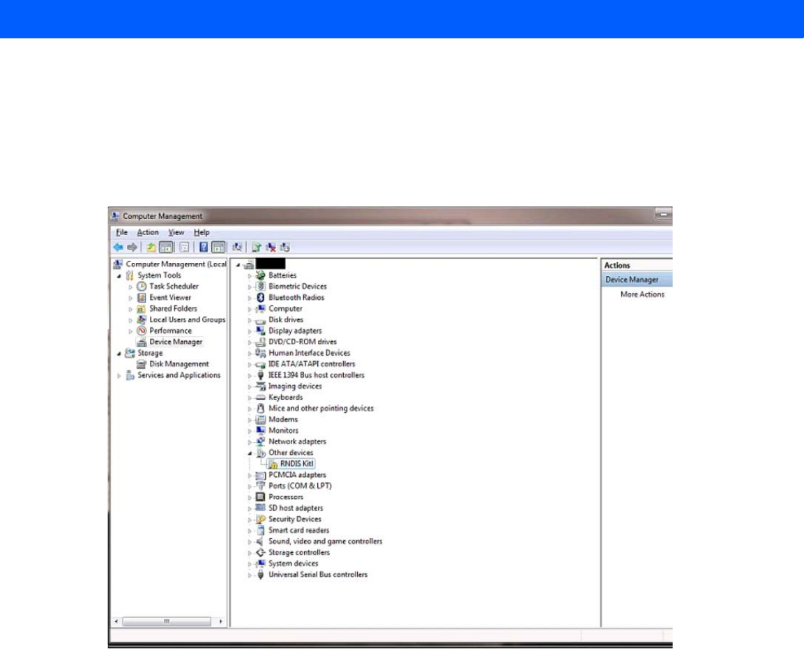
1. After connecting a USB cable between the PC and reader, the RNDIS driver automatically installs. If it
does not, right-click on Computer and select Manage. From System Tools, select Device Manager.
Under Other Devices, look for an entry for RNDIS with an exclamation icon indicating that the driver was
not installed.
Figure 3-3
Computer Management Window
2. Right-click the icon and select Update Driver Software. Search for the device driver software by clicking
on Browse my computer for driver software.
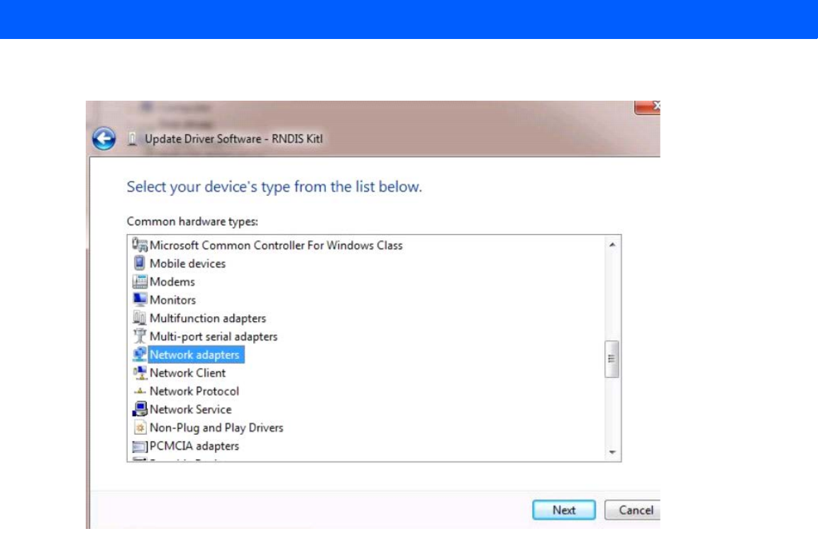
3. Select Let me pick from a list of device drivers on my computer.
Draft 2
3 - 8 FX7500 RFID Reader Integrator Guide
4. Select Network adapters.
Figure 3-4
Selecting Device Type
5. Select Microsoft Corporation from the manufacturer list.
6. Under Network Adapter, select Remote NDIS Compatible Device, and click Next.
After installation, the PC recognizes the reader as an RNDIS device. The PC obtains the IP address
169.254.10.102, and the reader is reachable at the IP address 169.254.10.1.
Sample Implementation
This implementation assumes that only one FX7500 reader is connected to a host PC via USB. This feature
does not function with multiple readers connected to the host. Zebra recommends disabling any other network
interface on the PC.
Use an application that uses RFID3 APIs such as Power Session, or use an LLRP application to connect to the
reader to read tags.
1. The primary RFID server connects to the FX7500 via the Ethernet interface.
2. The host PC connects to the FX7500 via the USB port. An application on the host PC monitors
communication between the primary RFID server and FX7500 reader.
3. When the application on the host PC detects a communication failure between the primary RFID server
and the reader, it connects to and controls the reader using the USB virtual interface.
Draft 2

Installation and Communication 3 - 9
4. The FX7500 listens on the USB virtual interface on a fixed port (49152) as well as on the standard LLRP
port (5084). To enable this, select the Allow LLRP Connection Override check box in Configure LLRP
Settings console window.
Figure 3-5
Communication / Configure LLRP Settings Window
Only one LLRP session can be active on the reader, either through the primary Ethernet interface or through
the virtual network over USB interface.
If a connection is active on one interface, a subsequent connection attempt on a second interface disconnects
the first. The second connection attempt always prevails and creates a new session.
GPIO Interface Connection
This pluggable terminal block type allows connecting individual wires independently. A single connector
accommodates both inputs and outputs. See Table A-5 on page A-6 for pinout information.
GPIO signals allow some flexibility. Inputs are pulled up within the reader to +5 VDC and can be shorted to
ground to pull them low. This allows driving them directly via simple relay or switch contacts. Alternatively, 5V
logic can drive inputs. In the logic low state, the current sourced from the reader is approximately 3 mA, so
standard gates in most logic families can drive them. Current flow in the high state is negligible. When the
equipment uses an external +24 VDC power supply, a +24 VDC connection is provided. This output is not
available when an external 24 VDC supply is not present.
The general purpose outputs are open-drain drivers, pulled up to 5V. Each output can withstand voltages up to
+30 VDC but should not be driven negative. For best results use the +24 VDC supply as a source of external
current and use the outputs directly to drive 24V relays, indicator lamps, etc., wired between the 24V supply
and individual general purpose outputs. Although each output can sink up to 1A, the maximum current that can
be drawn from the internal 24V supply is 1A, so use an external power supply if the current requirement
exceeds this. Note that the state of the general purpose outputs is inverted, e.g., driving a GPO line high at the
processor pulls the corresponding output low.
NOTE Do not connect the +24 VDC output directly to either general purpose input that tolerates voltages in
excess of 5V but is designed to operate optimally within the range of 0 to +5 VDC.
Draft 2

3 - 10 FX7500 RFID Reader Integrator Guide
Powering the Reader
Powering the Reader via AC Power Supply
The approved AC power supply connects to the power port on the FX7500 reader using a locking connector
(see Figure 2-4 on page 2-4). The power supply is compatible with:
•
120V 60 Hz (North America)
•
230V 50 Hz (International excluding Japan)
•
100V 50/60 Hz (Japan).
1. Insert the power supply barrel connector into the reader power port (see Figure 2-4 on page 2-4). Rotate
the connector to lock it in place.
2. Apply power to the power supply. The green Power LED stays on to indicate the reader is powered and
ready. See System Start-up/Boot LED Sequence on page 3-11.
To power down the reader, unplug the power supply from its power source. The green Power LED turns off to
indicate that the device is off and the system is not operational. Remove the connector from the reader power
port.
Powering the Reader via Power-over-Ethernet (POE)
Connect the reader to either a standard POE or POE+ injectors.
1. Insert the POE Ethernet connector on the RJ45 Ethernet cable into the reader 10/100BaseT Ethernet port.
See Figure 2-4 on page 2-4.
2. Connect the other end of the cable to an Ethernet network with POE capability. See System Start-up/Boot
LED Sequence on page 3-11.
To power down the reader, remove the Ethernet cable from the network. The green Power LED turns off to
indicate that the device is off and the system is not operational. Remove the connector from the 10/100BaseT
Ethernet port.
CAUTION Connect the antennas before supplying power to the reader.
WARNING!For Mounting in Environmental Air Handling Space (EAHS): Do not install Power Supplies and
PoE (Power Injector) in the EAHS unless they are suitable for use in EAHS as per UL 2043.
Draft 2

Installation and Communication 3 - 11
LED Sequences
System Start-up/Boot LED Sequence
See Figure 2-5 on page 2-5 for LED locations. During system start-up:
1. All LEDs turn on for a few seconds when power is applied to the reader.
2. All LEDs turn off and the PWR LED turns amber.
3. The PWR LED turns green to indicate successful RFID application initialization.
4. When the sequence completes, the green PWR LED remains on and all other LEDs are off.
PWR LED Sequence to Indicate IPv4 Status after Booting
After the RFID application initializes:
1. The PWR LED turns green for 5 seconds to indicate success (following the sequence from System
Start-up/Boot LED Sequence).
2. The reader checks the eth0 IPv4 address and indicates the IPv4 status using the LEDs:
•
If the reader has a DHCP address, the PWR LED blinks green for 3 seconds.
•
If the reader has static IP address, the PWR LED blinks amber 3 seconds.
•
If the reader has an IP address from zero-configuration networking algorithm, the PWR LED blinks red
for 3 seconds.
•
If the reader doesn't have valid IP, the PWR LED blinks amber and green using a 90-second timeout to
indicate that it is waiting to acquire an IP address.
•If it obtains a valid IP within the timeout period, the reader indicates the status as described above.
•If the timeout expires before the reader obtains an IP, the PWR LED stops blinking.
3. The PWR LED again turns solid green.
Reset to Factory Defaults LED Sequence
Holding the reset button for 8 seconds resets the reader to the factory default configuration.
1. All LEDs turn on as usual when you press and hold the reset button.
2. The PWR LED blinks amber when the reset button is held.
3. The PWR LED blinks green fast 5 times to indicate that the reader detects a reset operation.
4. Release the reset button to reset the reader to factory defaults.
LED Sequence for Software Update Status
1. The PWR LED blinks red during the software update process.
2. After reset, the STAT LED blinks red if the radio module requires a firmware update.
Draft 2

3 - 12 FX7500 RFID Reader Integrator Guide
Reading Tags
After the reader powers up, test the reader. See System Start-up/Boot LED Sequence on page 3-11.
1. Enable tag reading using the web-based Administrator Console (see Read Tags on page 4-30) or control
the reader through a real-time application such as Power Session.
2. Present a tag so it is facing the antenna and slowly approach the antenna until the activity LED turns
green, indicating that the reader read the tag. See Figure 2-5 on page 2-5. The distance between the tag
and the antenna is the approximate read range.
NOTE For optimal read results, do not hold the tag at an angle or wave the tag, as this can cause the read
distance to vary.
Draft 2

CHAPTER 4 ADMINISTRATOR CONSOLE
Introduction
This chapter describes the FX7500 Reader Administrator Console functions and procedures. Access the
Administrator Console using a web browser from a host computer, and use this to manage and configure the
readers. The Administrator Console main window and support windows have four areas, each containing
unique information about the reader.
•
Selection Menu - selects the function for the primary information window.
•
Primary Information Window - provides the primary function information.
•
Product Identification Header - identifies the product.
•
USB Port Status - provides details on the USB device connected to the USB host port. Hover the mouse
pointer over the blue link, available only when a device is detected.
•
Help Information Window:
•provides detailed information to support the primary information window
•includes a scroll bar to scroll through information
•includes a toggle button to turn on/off the help information window
NOTE The screens and windows in this chapter may differ from actual screens and windows. The applications
described may not be available on (or applicable to) all devices. Procedures are not device-specific and
are intended to provide a functional overview.
Draft 2
4 - 2 FX7500 RFID Reader Integrator Guide
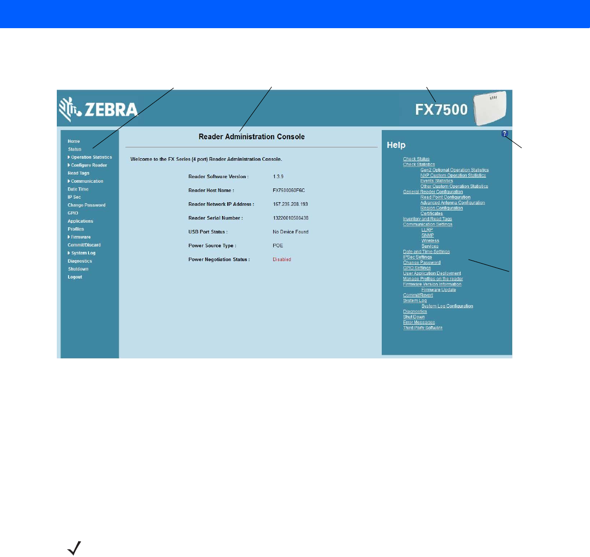
Figure 4-1
Reader Administrator Console Main Menu
Profiles
Use profiles for multiple reader deployments to save configuration time, as only a few APIs are needed to
completely configure a reader. See Reader Profiles on page 4-43.
Resetting the Reader
To reset the reader, press and hold the reset button for not more than 2 seconds. See Figure 2-4 on page 2-4
for the reset button location. The reader reboots but retains the user ID and password. See System
Start-up/Boot LED Sequence on page 3-11.
Selection
Menu Primary Information Window Product Identification Header
Help
Information
Window
Toggle
On/Off
Button
Help
Information
Window
NOTE Hard rebooting the reader (disconnecting power) is not recommended as this discards all the tag events
and system log information.
Draft 2

Administrator Console 4 - 3
Connecting to the Reader
To use the Administrator Console to manage the reader, first power up the reader and connect it to an
accessible network. See Powering the Reader on page 3-10 and Ethernet Connection on page 3-5. The green
power LED indicates that the reader is ready. If the green power LED is not lit, reset the reader. See Resetting
the Reader on page 4-2.
Connect to the reader in one of two ways:
1. Connecting via Host Name on page 4-3
2. Connecting via IP Address on page 4-4
There are three ways to assign an IP address to the reader:
1. Using DHCP on the network
2. Using Zero-Configuration Networking when DHCP Server is Not Available on page 4-5
3. Statically assigning an IP
Any method of assigning the IP supports connection using host name or IP address. Alternatively, connect the
reader directly to a local computer using zero-configuration networking. See Using Zero-Configuration
Networking when DHCP Server is Not Available on page 4-5.
Connecting via Host Name
To connect to the reader using the host name:
1. Open a browser. Recommended browsers are IE10 (disabling Compatibility View is recommended),
Chrome v29, and FireFox 24.
2. Enter the host name provided on the reader label in the browser (e.g., http://fx7500cd3b0d) and press
Enter. The Console Login window appears and the reader is ready.
NOTE This section describes procedures in a Windows environment.
NOTE When using zero-configuration networking, the FX7500 reader cannot communicate with computers on
different subnets, or with computers that do not use automatic private IP addressing.
CAUTION Reader host name is not guaranteed to work at all times. Its recommended use is only in networks
where the probability for IP collisions is low, such as a network in which a DNS server is configured to
work together with DHCP to register host names. Host name usage is not recommended in a network
where there is no strict control to prevent IP collisions, such as informal networks that use IP static
configuration without strict control.
Draft 2

4 - 4 FX7500 RFID Reader Integrator Guide
3. Proceed to Administrator Console Login on page 4-6 to log in to the reader.
Auto Discovery
The FX7500 can automatically belong to a network. The reader implements WS-Discovery conforming to RFID
Reader Management Profile (RDMP) specification in ISO 24791-3. RDMP is based on an extension for Device
Profile for Web Services (DPWS). The discovery mechanism is limited to subnets and does not work across
subnets. The Power Session application supports this feature, and it lists the discovered reader using reader
hostnames. Because this feature is based on WS-Discovery, the readers can also be discovered in Windows
Vista and Windows 7 computers by clicking on the Network icon in a file browser.
Connecting via IP Address
To use the IP address to connect to the reader:
1. Open a browser. Recommended browsers are IE10 (disabling Compatibility View is recommended),
Chrome v29, and FireFox 24.
2. Enter the IP address in the browser (e.g., http://157.235.88.99) and press Enter. The Console Login
window appears and the reader is ready.
3. Proceed to Administrator Console Login on page 4-6 to login to the reader.
NOTE Connect the reader to a network that supports host name registration and lookup to ensure the network
can access the reader using the host name. For instance, some networks can register host names
through DHCP. When first connecting to the reader, it is recommended to keep DHCP enabled in both the
PC and the reader, although it is not guaranteed that the host name will work all the time. Use the host
name printed on the reader label, or construct it using the reader MAC address on the reader back label.
The host name is a string with prefix FX7500, followed by the last three MAC address octets. For
example, for a MAC address of 00:15:70:CD:3B:0D, use the prefix FX7500, followed by the last three
MAC address octets (CD, 3B, and 0D), for the host name FX7500CD3B0D. Type http://FX7500CD3B0D
in the browser address bar to access the reader.
For a network that does not support host name registration and lookup, use the Power Session auto
discovery feature to obtain the IP address, and use the IP address connect method.
Draft 2
Administrator Console 4 - 5
Using Zero-Configuration Networking when DHCP Server is Not Available
If a DHCP server is not available, the FX7500 reader can use zero-configuration networking to automatically
provide a unique network IP address. The reader can then use TCP/IP to communicate with other computers
also using a zero-configuration networking-generated IP address.
The zero-configuration networking procedure is recommended when the reader is connected directly to a PC.
It reduces the overhead needed to configure the reader to a static IP address.
When zero-configuration networking executes after failing to detect a DHCP server, the reader automatically
assigns an IPv4 IP address to the Ethernet interface in the form 169.254.xxx.xxx. This IP address is
predictable because it uses the last 2 bytes of the MAC address, usually represented as HEX values, to
complete the IPv4 address. These values are converted to decimal format (e.g., if the MAC address ends with
55:9A, the IPv4 address assigned by the zero-configuration algorithm is 169.254.85.148.
Windows-based computers support APIPA/zero-configuration networking by default when DHCP fails.
To enable APIPA for a Windows PC, visit http://support.microsoft.com/ and search for APIPA.
Obtaining the IP Address via Command Prompt
The Administrator Console provides the reader IP address. See Figure 4-1 on page 4-2. To obtain the reader IP
address without logging into the reader, open a command window and ping the reader host name. See
Connecting via Host Name on page 4-3.
Figure 4-2
IP Ping Window
NOTE When using zero-configuration networking, the FX7500 reader cannot communicate with computers on
different subnets, or that do not use automatic private IP addressing. Automatic private IP addressing is
enabled by default.
Draft 2
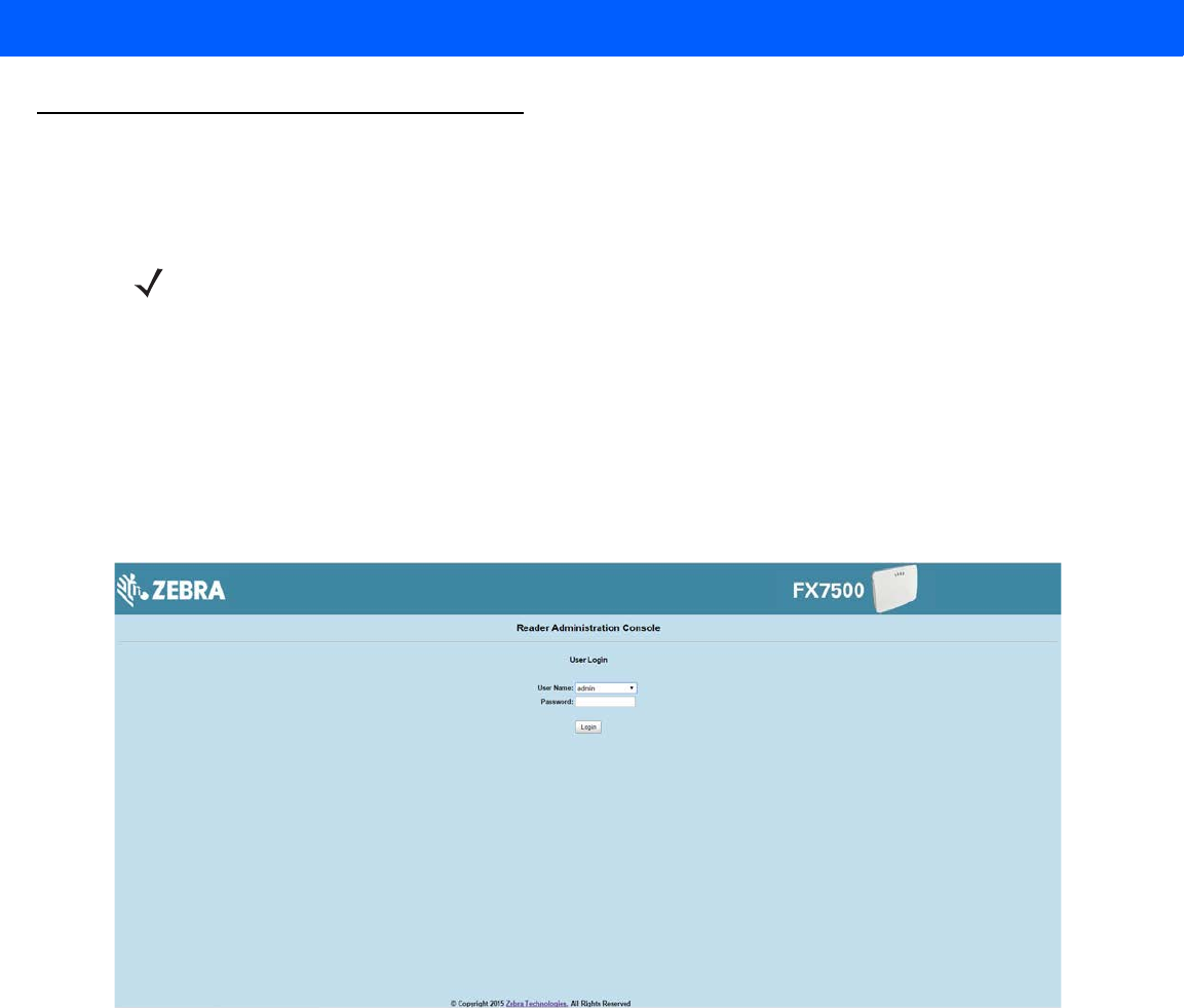
4 - 6 FX7500 RFID Reader Integrator Guide
Administrator Console Login
The reader has a unique first time startup sequence that requires setting a unique user ID and password and
as well as the region (regulatory requirement).
First Time / Start-Up Login
When starting the reader for the first time, set a unique user ID and password and set the region of reader
operation. Setting the reader to a different region is illegal.
Logging In with Default User ID and Password
1. Upon connecting to the reader with a web browser, the User Login window appears.
Figure 4-3
User Login Window
2. Enter admin in the User Name: field and change in the Password: field and click Login.
For global reader configurations, the Region Configuration window appears. For US reader configurations, the
Administrator Console main window appears.
NOTE The recommended browsers are IE10 (disabling Compatibility View is recommended), Chrome v29, and
FireFox 24. These browsers were tested and validated to work properly. Other browsers may or may not
work properly.
Draft 2
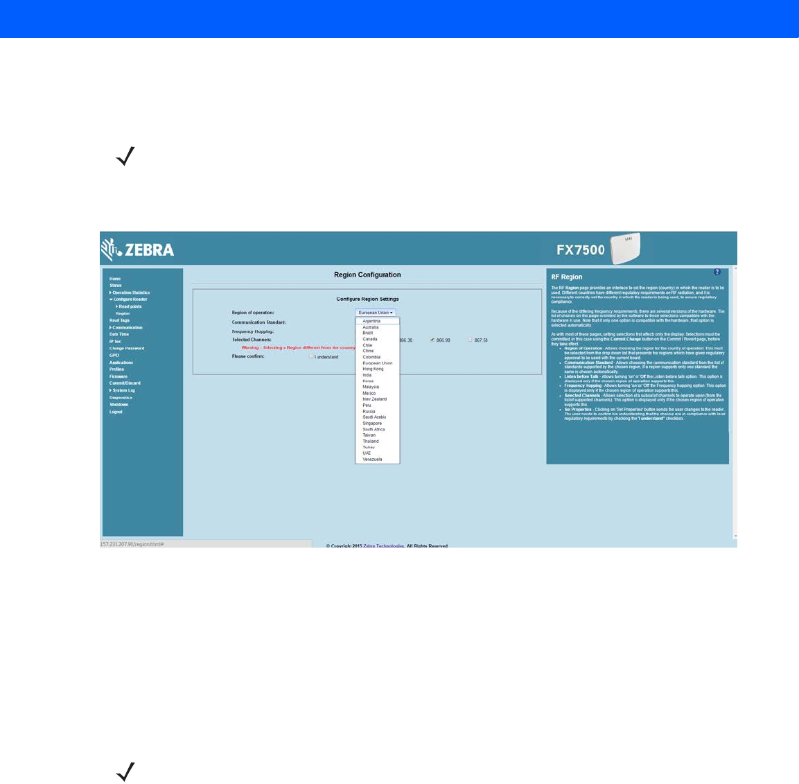
Administrator Console 4 - 7
Setting the Region
For global reader configurations, set the region of operation. Setting the unit to a different region is illegal.
1. In the Configure Region Settings window, select the region from the drop-down menu.
Figure 4-4
Selecting the Region
2. Select the Communication Standard if applicable.
3. Select Frequency Hopping, if applicable.
4. Select the appropriate channel(s), if applicable.
5. Click the I understand check box.
6. Click Set Properties to complete the region selection. The Operation Successful window appears.
7. Select Commit/Discard from the selection menu.
NOTE Region configuration is not available for readers configured to operate in the United States region (under
FCC rules). In this case, skip this step.
NOTE Most changes to the reader require a commit to save them.
Draft 2
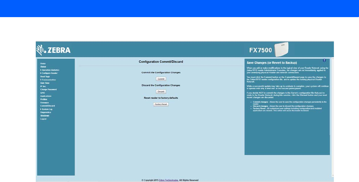
4 - 8 FX7500 RFID Reader Integrator Guide
Figure 4-5
Commit/Discard Window
8. Click Commit to apply the changes to the reader configuration file, or Discard to discard the new region
configuration changes.
When the commit completes, the Commit Successful window appears. The region is now set and stored in
the reader.
Draft 2
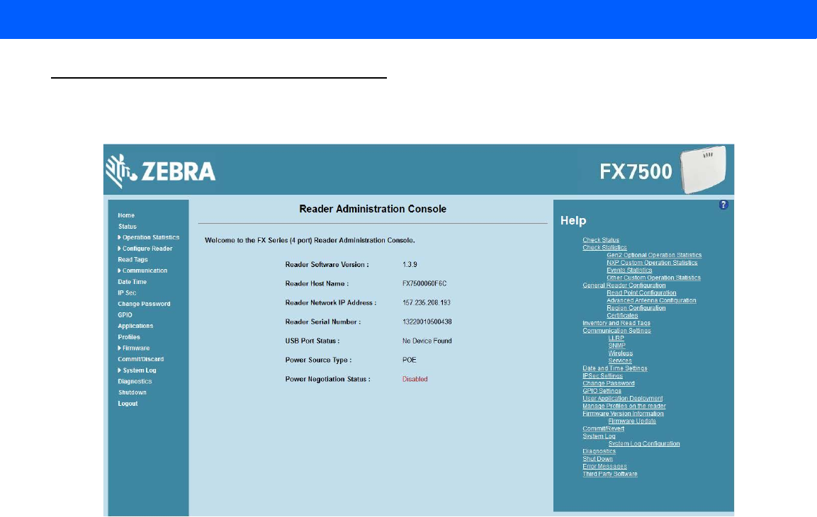
Administrator Console 4 - 9
Reader Administrator Console
The Reader Administrator Console main window appears after successfully logging into the reader.
Figure 4-6
Reader Administrator Console Main Window
Administrator Console Option Selections
Click an item from the selection menu on the left to select:
•
Status - see Status on page 4-10
•
Operation Statistics - see Reader Statistics on page 4-11
•Gen2 Optional - see Reader Gen2 Optional Operation Statistics on page 4-12
•NXP - see NXP Custom Command Operation Statistics on page 4-13
•Events
- see Event Statistics on page 4-14
•Other Custom - see Other Custom Command Operation Statistics on page 4-15
•
Configure Reader - see Configure Reader on page 4-16
•Read Points - see Read Points on page 4-17
•Advanced - see Read Points - Advanced on page 4-18
•Region - see Configure Region on page 4-19
•Certificates - see Certificates on page 4-20
•
Read Tags - see Read Tags on page 4-30
Draft 2

4 - 10 FX7500 RFID Reader Integrator Guide
•
Communication - see Communication Settings on page 4-31
•LLRP - see Configure LLRP Settings on page 4-34
•SNMP - see SNMP Settings on page 4-35
•Wireless - see Wireless Settings on page 4-36
•Services - see Network Services Settings on page 4-37
•
Date/Time - see System Time Management on page 4-38
•
IP Sec - see IPV6 IP Sec on page 4-39
•
Change Password - see Change Password on page 4-40
•
GPIO - see GPIO on page 4-41
•
Applications - see Applications on page 4-42
•
Profiles - see Reader Profiles on page 4-43
•
Firmware - see Firmware Version/Update on page 4-44
•Update - see Firmware Update on page 4-45
•
Commit/Discard - see Commit/Discard on page 4-45
•
System Log - see System Log on page 4-46
•Configure - see Configure System Log on page 4-47
•
Diagnostics - see Reader Diagnostics on page 4-48
•
Shutdown - see Shutdown on page 4-49
•
Logout - click Logout to immediately log out of the Administrator Console.
Status
Click Status on the selection menu to view the Reader Status window. This window displays information about
the reader and read points (antennas).
Figure 4-7
Reader Status Window
Draft 2
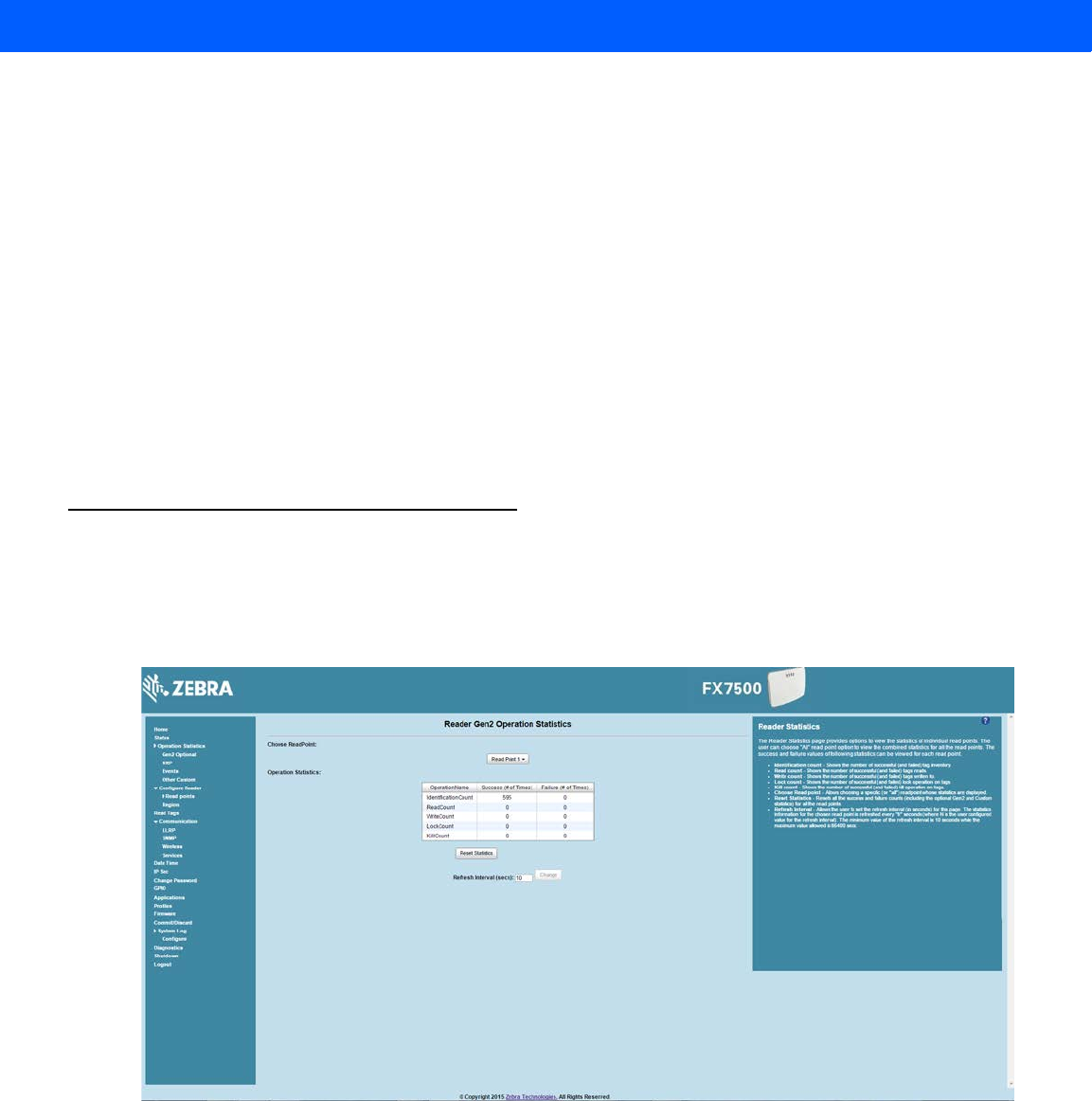
Administrator Console 4 - 11
The Reader Status window provides consolidated reader status information:
•
System Clock: The current system clock value, in the format of [Year] [Month] [Day] [Hour: Minute:
Second] [Time Difference with UTC]. Click the link to adjust the reader date and time settings.
•
Up Time - Displays how long the reader has been running, in the format [Number of Days] [Number of
Hours] [Number of Minutes] [Number of Seconds].
•
CPU Usage: Displays the CPU usage for the system and reader applications, including customer
applications.
•
RAM Usage: Displays the total allocated RAM for the reader application and customer applications (if
any), the memory used, and the free memory.
•
Flash Usage: Displays the flash memory usage by partition.
•
Refresh Interval - Sets the refresh interval (in seconds) for the window. The status information refreshes
every N seconds (where N is the user configured value for the refresh interval). The minimum refresh
interval value is 10 seconds; the maximum allowed is 86,400 seconds.
Reader Statistics
Select Operation Statistics to view the Reader Operation Statistics window. This window provides options to
view the statistics of individual read points or combined statistics for all read points, including the success and
failure values of statistics for each read point. The statistic count is cumulative once the reader starts or the
Reset Statistics button is selected.
Figure 4-8
Reader Operation Statistics Window
•
Choose ReadPoint - Select a specific read point or select All from the drop-down list to display the
statistics.
•
IdentificationCount - Displays the number of successful (and failed) tag inventories.
•
ReadCount - Displays the number of successful (and failed) tag reads.
•
WriteCount - Displays the number of successful (and failed) tag writes.
•
Lockcount - Displays the number of successful (and failed) lock operations on tags.
Draft 2
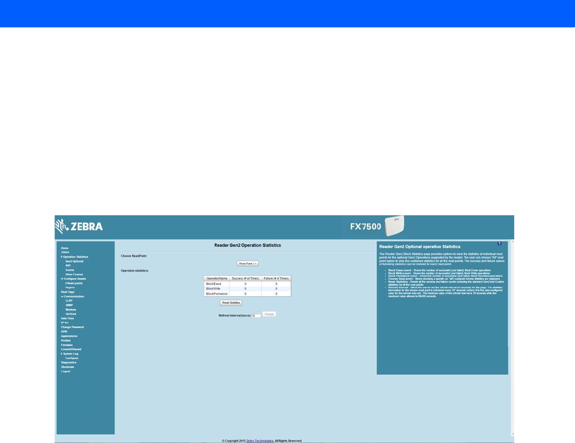
4 - 12 FX7500 RFID Reader Integrator Guide
•
KillCount - Displays the number of successful (and failed) kill operations on tags.
•
Reset Statistics - Resets all success and failure counts (including the optional Gen2 and Custom
statistics) for all read points.
•
Refresh Interval - Sets the refresh interval (in seconds) for this window. The statistics information for the
chosen read point is refreshed every N seconds (where N is the set refresh interval). The minimum value
is 10 seconds and the maximum value allowed is 86,400 seconds. Input a new value and click Change to
set a new interval.
Reader Gen2 Optional Operation Statistics
Select Gen2 Optional to view the Reader Gen2 Operation Statistics window. This window provides options to
view the statistics of read points for the optional Gen2 operations the reader supports.
Figure 4-9
Reader Gen2 Operation Statistics Window
•
Choose ReadPoint - Select a specific read point from the drop-down list to display the statistics, or select
All to view the combined statistics for all read points.
•
BlockErase - Displays the number of successful (and failed) block erase operations.
•
BlockWrite - Displays the number of successful (and failed) block write operations.
•
BlockPermalock - Displays the number of successful (and failed) block permalock operations.
•
Reset Statistics - Resets all success and failure counts (including the standard Gen2 and custom
statistics) for all read points.
•
Refresh Interval - Sets the refresh interval (in seconds) for this window. The statistics information for the
chosen read point is refreshed every N seconds (where N is the set refresh interval). The minimum value
is 10 seconds and the maximum value allowed is 86,400 seconds. Input a new value and click Change to
set a new interval.
Draft 2
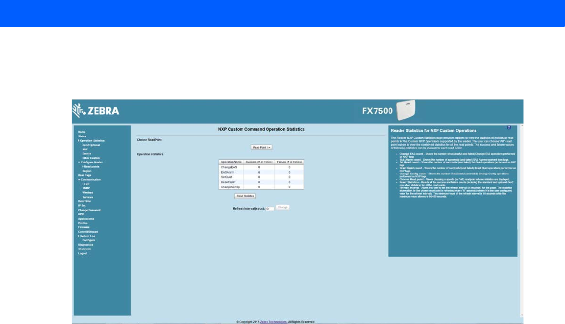
Administrator Console 4 - 13
NXP Custom Command Operation Statistics
Select NXP to view the NXP Custom Command Operation Statistics window. This window provides options to
view the statistics of read points for the custom NXP operations the reader supports.
Figure 4-10
NXP Custom Command Operation Statistics Window
•
Choose ReadPoint - Select a specific read point from the drop-down list to display the statistics, or select
All to view the combined statistics for all read points.
•
ChangeEAS - Displays the number of successful (and failed) change EAS operations performed on NXP
tags.
•
EASAlarm - Displays the number of successful (and failed) EAS alarms received from tags.
•
SetQuiet - Displays the number of successful (and failed) set quiet operations performed on NXP tags.
•
ResetQuiet - Displays the number of successful (and failed) reset quiet operations performed on NXP
tags.
•
ChangeConfig - Displays the number of successful (and failed) change configuration operations
performed on NXP tags.
•
Reset Statistics - Resets all the success and failure counts (including the standard and optional Gen2
operation statistics) for all the read points.
•
Refresh Interval - Sets the refresh interval (in seconds) for this window. The statistics information for the
chosen read point is refreshed every N seconds (where N is the set refresh interval). The minimum value
is 10 seconds and the maximum value allowed is 86,400 seconds. Input a new value and click Change to
set a new interval.
Draft 2
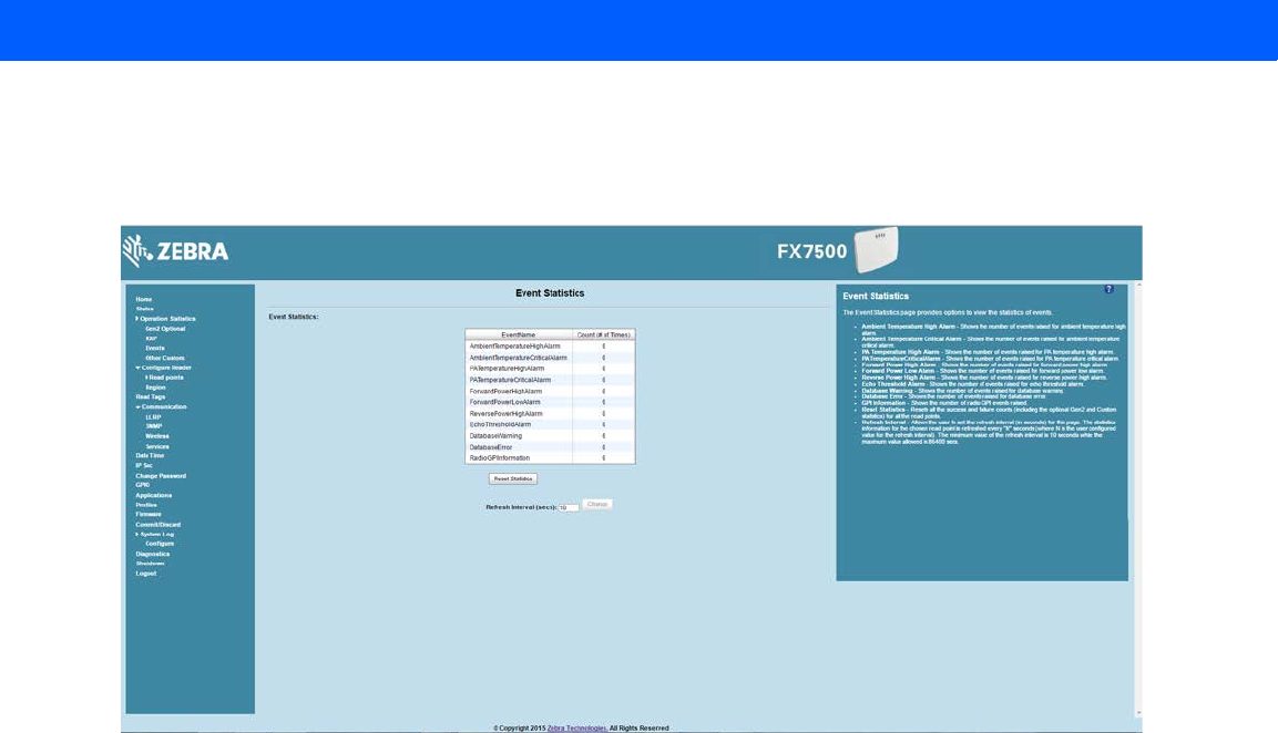
4 - 14 FX7500 RFID Reader Integrator Guide
Event Statistics
Select Events to view the Events Statistics window. This window provides options to view the statistics of
events.
Figure 4-11
Event Statistics Window
•
AmbientTemperatureHighAlarm - Displays the number of events raised for ambient temperature high
alarm.
•
AmbientTemperatureCriticalAlarm - Displays the number of events raised for ambient temperature
critical alarm.
•
PATemperatureHighAlarm - Displays the number of events raised for PA temperature high alarm.
•
PATemperatureCriticalAlarm - Displays the number of events raised for PA temperature critical alarm.
•
ForwardPowerHighAlarm - Displays the number of events raised for forward power high alarm.
•
ForwardPowerLowAlarm - Displays the number of events raised for forward power low alarm.
•
ReversePowerHighAlarm - Displays the number of events raised for reverse power high alarm.
•
EchoThresholdAlarm - Displays the number of events raised for echo threshold alarm.
•
DatabaseWarning - Displays the number of warning events raised whenever the radio tag list buffer is
almost full.
•
DatabaseError - Displays the number of events raised when the radio tag list buffer is full.
•
GPIInformation - Displays the number of events raised for radio GPI events.
•
Reset Statistics - Resets all the success and failure counts for all the read points.
•
Refresh Interval - Sets the refresh interval (in seconds) for this window. The statistics information for the
chosen read point is refreshed every N seconds (where N is the set refresh interval). The minimum value
is 10 seconds and the maximum value allowed is 86,400 seconds. Input a new value and click Change to
set a new interval.
Draft 2
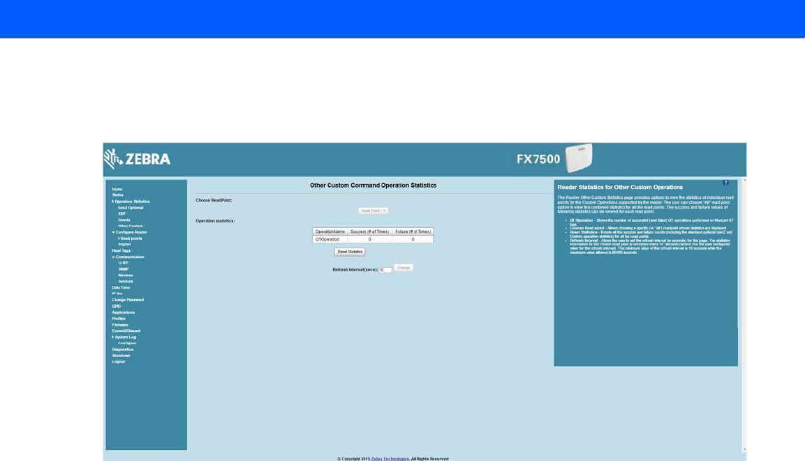
Administrator Console 4 - 15
Other Custom Command Operation Statistics
Select Other Custom to view the Other Custom Command Operation Statistics window. This window provides
options to view the statistics of read points for the custom operations the reader supports.
Figure 4-12
NXP Custom Command Operation Statistics Window
•
Choose ReadPoint - Select a specific read point from the drop-down list to display the statistics, or select
All to view the combined statistics for all read points.
•
QTOperation - Displays the number of successful (and failed) QT operations performed on Monza4 QT
tags.
•
Reset Statistics - Resets all the success and failure counts for all the read points.
•
Refresh Interval - Sets the refresh interval (in seconds) for this window. The statistics information for the
chosen read point is refreshed every N seconds (where N is the set refresh interval). The minimum value
is 10 seconds and the maximum value allowed is 86,400 seconds. Input a new value and click Change to
set a new interval.
Draft 2
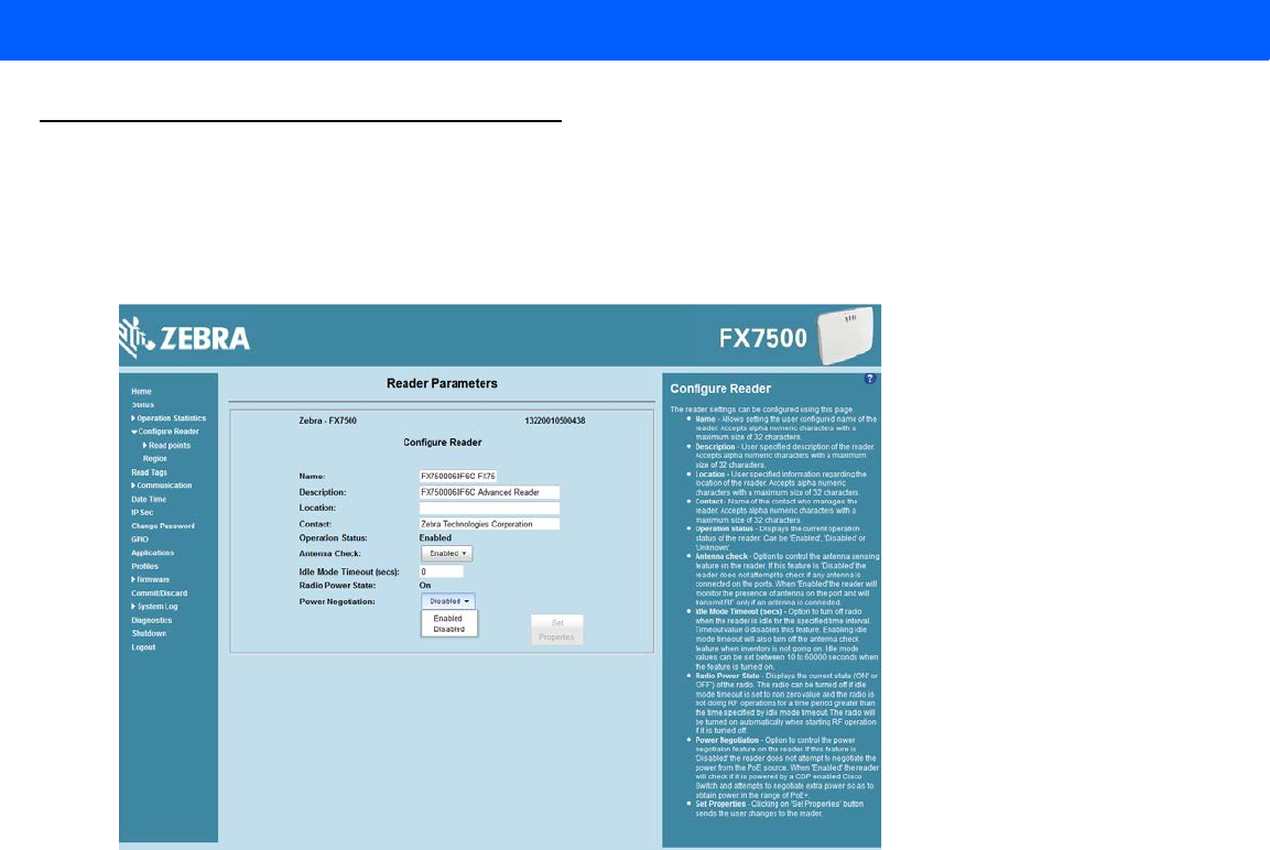
4 - 16 FX7500 RFID Reader Integrator Guide
Configure Reader
Use the Configure Reader submenus to access the following functions.
Reader Parameters (General)
Select Configure Reader in the selection menu to configure reader settings using this window.
Figure 4-13
Reader Parameters
•
Name - Sets the user-configured reader name. Accepts up to 32 alphanumeric characters.
•
Description - Sets a user-configured reader description. Accepts up to 32 alphanumeric characters.
•
Location - Enter information on the reader location. Accepts up to 32 alphanumeric characters.
•
Contact - Enter the name of the reader manager contact. Accepts up to 32 alphanumeric characters.
•
GPI Debounce Time - Delays input events up to this time, and delivers these events only if the PIN
states remains on the same level.
•
Operation Status - Displays the current operation status of the reader (Enabled, Disabled, or
Unknown).
•
Antenna Check - Controls the antenna sensing feature on the reader. Disabled indicates that the
reader does not attempt to check if an antenna is connected on the ports. When Enabled, the reader
monitors the presence of an antenna on the port and only transmits RF if an antenna is connected.
•
Idle Mode Timeout (secs) - Turns off the radio when the reader is idle for the specified time interval. A
value of 0 disables this feature. Enabling this also turns off the antenna check feature when idle mode is
entered after time out.
•
Radio Power State - Displays the current state (On or Off) of the radio. The radio can be turned off if the
Idle Mode Timeout is set to a non-zero value and the radio is not performing RF operations for a time
period greater than the time specified by this timeout. The radio turns on automatically when RF
operation starts.
Draft 2
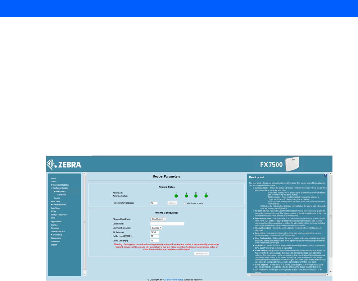
Administrator Console 4 - 17
•
Power Negotiation - When the Power Negotiation option is set as enabled, and committed, the FX7500
reader starts power negotiation. Power negotiation occurs only if the reader is powered from a switch
that is capable of LLDP based power negotiation. If the reader is powered from a source that does not
support LLDP, power negotiation can still be enabled and disabled, but the reader does not carry out any
power negotiation.
The moment the power source is switched to an LLDP enabled switch, power negotiation occurs at
startup if it was enabled from the UI previously.
After power negotiation is enabled, and committed, it takes approximately 2 to 5 minutes to reach the
PoE+ level. This is the time taken for LLDP packet exchange between the reader and the switch for
power negotiation.
These settings only affect the display. Use Commit/Discard on page 4-45 to save the changes.
Read Points
Click Read points in the selection menu to configure the read point settings and view the current read points
state.
Figure 4-14
Configure Read Points
Antenna Status
•
Status buttons - indicate the status of the reader read points:
•Green: Connected - Read point is enabled and an antenna is connected to the port.
•Red: Not connected - Read point is enabled, but no antenna is connected to the port.
•Yellow: User disabled - The user disabled the read point.
Click a read point’s status button to view and/or change the selected antenna configuration.
•
Refresh Interval - Sets the refresh interval (in seconds) to update the readpoint status. The minimum
value is 10 seconds and the maximum value allowed is 86,400 seconds. Input a new value and click
Change to set a new interval.
•
Maintenance mode - Places the reader in maintenance mode which intermittently drives PWR, ACT,
and STAT LEDs to easily locate the reader. Also enables quick reporting of antenna status by setting the
refresh interval to 2 seconds. Note that you can not modify the refresh interval in this mode.
Draft 2
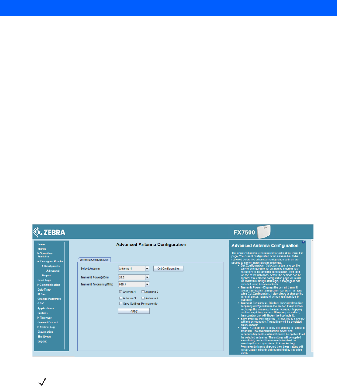
4 - 18 FX7500 RFID Reader Integrator Guide
Antenna Configuration
•
Choose Read Point - Select a read point to display the configuration.
•
Description - Enter a read point description of up to 32 alphanumeric characters.
•
User Configuration - Enable or disable the read point. Disabling a read point blocks RF operation using
the port/antenna.
•
Air Protocol - Displays the air protocols the read point supports. The reader currently supports only EPC
Class1 GEN2 air protocol.
•
Cable loss (dB/100 ft) - Specifies the cable loss in terms of dB per 100 feet length for the antenna cable
that is used to connect this read point port to the antenna. Refer to the specification of the antenna cable
for this information. The default value is 0. Setting this and the cable length to non-zero values allows the
compensating for the RF signal loss in the cable due to attenuation by specifying an appropriate increase
in the transmit power for this read point. The reader uses this and the cable length value to internally
calculate the cable loss. The calculated cable loss is internally added to the power level configured on
the read point.
•
Cable length (ft) - Sets the cable length in feet of the physical cable that connects the read point port to
the antenna.
•
Set Properties - Select Set Properties to apply the changes. Select Commit/Discard on page 4-45 to save
the changes to the reader.
Read Points - Advanced
Click Advanced under Read points in the selection menu to view the Advanced Antenna Configuration window.
Use this window to modify the transmission power and frequency configuration elements of the antenna.
Figure 4-15
Advanced Antenna Configuration
Retrieve the current configuration of an antenna before applying the advanced configuration settings.
NOTE This page is not supported when LLRP is configured in secure mode.
Draft 2
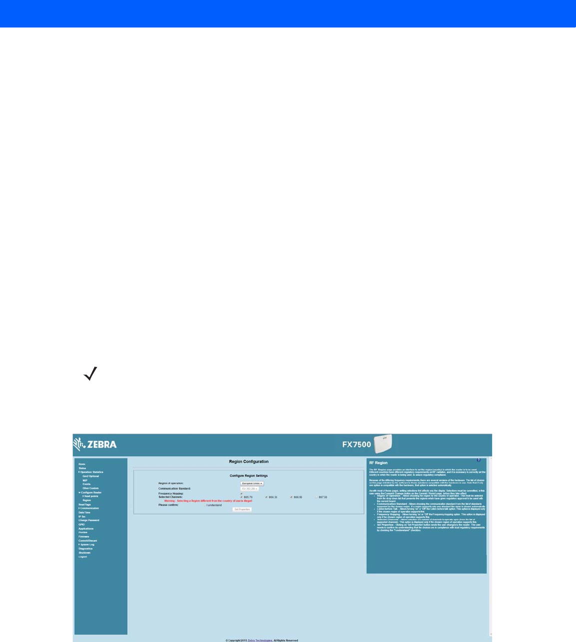
Administrator Console 4 - 19
•
Get Configuration - Select an antenna to get the current configuration for that antenna. After login, you
must get the antenna configuration for an antenna before settings can be applied. The antenna
configuration page retains the retrieved settings after login if you do not refresh the page using browser
refresh.
•
Transmit Power - Displays the current transmit power setting after selecting Get Configuration, and
allows changing the transmit power for that antenna. This transmit power level does not include cable
loss compensation.
•
Transmit Frequency - Displays the active frequency configuration on the reader, and allows changing
the frequency for non-frequency hopping enabled regulatory regions. If hopping is enabled, the combo
box displays the hop table ID.
•
Save Settings Permanently - Check this to save the settings permanently and persist them across
reboots.
•
Apply - Click to apply the settings for the selected antennas. This applies the selected transmit power
and frequency/hop table configuration to all selected antennas. The settings are applied immediately and
have immediate effect on Inventory/Access operations. Also check Save Setting Permanently to persist
these settings across reboots unless modified by another client.
Configure Region
Different countries have different RF regulatory requirements. To assure regulatory compliance, select Region
to set the reader for specific regulatory requirements in the country of reader operation using the Configure
Region Settings window.
Because of the differing frequency requirements, there are several versions of the hardware. The list of
choices on this page is limited by the software to those selections compatible with the hardware in use. Note
that if only one option is compatible with the hardware, that option is selected automatically.
Figure 4-16
Configure Region Settings Window
•
Region of Operation - Select the region for the country of operation from the drop-down list. This list
includes regions which have regulatory approval to use with the current board.
NOTE Region configuration is not required for readers configured to operate in the United States region (under
FCC rules).
Draft 2

4 - 20 FX7500 RFID Reader Integrator Guide
•
Communication Standard - Select the communication standard from the list of standards that the chosen
region supports. If a region supports only one standard, it is automatically selected.
•
Frequency Hopping - Check to select frequency hopping. This option appears only if the chosen region of
operation supports this.
•
Selected Channels - Select a subset of channels on which to operate (from the list of supported
channels). This option appears only if the chosen region of operation supports this.
•
Please confirm - Check the I understand check box to confirm your understanding that the choices are in
compliance with local regulatory requirements.
•
Set Properties - Click to apply the changes. Select Commit/Discard on page 4-45 to save the changes to
the reader.
Certificates
You can protect network services on the reader using SSL/TLS to secure the communication channel against
eavesdropping or tampering, and optionally authenticate peer networked nodes involved in the
communication. SSL/TLS protocol uses Public Key Infrastructure digital certificates. The following services on
the reader support SSL/TLS:
•
Web Administrator Console service (HTTPS). See Network Services Settings on page 4-37.
•
File Transfer Service (FTPS - explicit SSL/TLS over FTP). See Network Services Settings on page 4-37.
•
Shell Service (SSH - by default always in secure mode).
•
Secure LLRP Service (refer to the EPC Global LLRP Standard, Security in TCP Transport). See the
Enable Secure Mode option in Configure LLRP Settings on page 4-34.
NOTE The supported version of SSL/TLS varies between services. Different services support SSL v3 and TLS
1.0 and above.
NOTE The Validate Peer option in Secure LLRP Service configuration enables authentication of reader and/or
clients using digital certificates. You must import a custom certificate (instead of the default self-signed
certificate) to the reader to enable this option. See Configure LLRP Settings on page 4-34 for details.
Services other than Secure LLRP rely on password-based authentication.
NOTE The SNMP service on the reader supports SNMP v2c and does not support security.
Draft 2
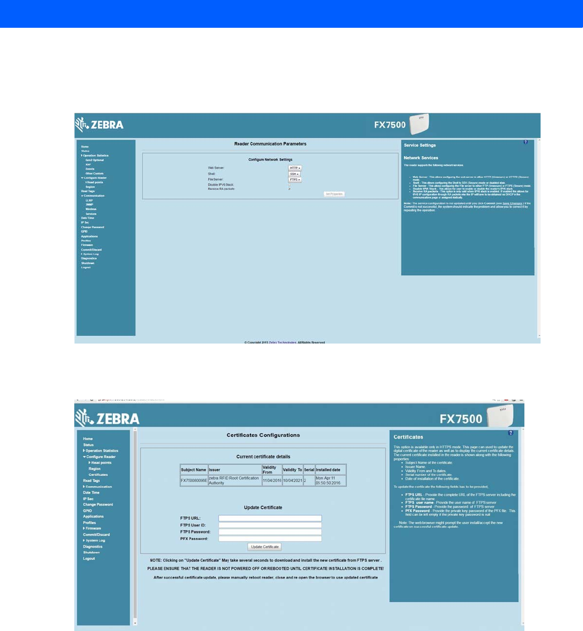
Administrator Console 4 - 21
Certificate Configuration
The Certificate Configuration page is available under the Configure Reader menu when the Administrator
Console is in HTTPS mode only. To enable HTTPS mode, select Communication > Services, and on the
Reader Communication Parameters page select HTTPS from the Web Server drop-down menu.
Figure 4-17
Setting HTTPS Mode
Select Configure Reader > Certificates. The Certificate Configuration page provides the current certificate
details and an option to update to a custom certificate.
Figure 4-18
Certificate Configuration Page
The Current certificate details section displays the installed certificate's details such as issuer, serial number,
and validity information.
By default, the reader uses self-signed certificates (characterized by Subject name and Issuer in Current
certificate details) for all secure interfaces using SSL/TLS.
Draft 2

4 - 22 FX7500 RFID Reader Integrator Guide
Self-signed certificates have restrictions, such as by default clients do not trust them because they are not
issued by a trusted Certification Authority (CA). Custom trusted certificates may be beneficial in certain use
cases, for example:
•
LLRP by default does not authenticate the client or reader. Security extensions to the standard allow
client or reader authentication using digital certificates. The entities involved validate digital certificates
by confirming the certificates were issued from a trusted source. Therefore a custom certificate is
required to authenticate the client or reader. See the Validate Peer option in Configure LLRP Settings on
page 4-34.
•
By default web browsers display a warning or prevent connection to the Administrator Console when
the console service is in HTTPS mode. See Network Services Settings on page 4-37. This can be an
inconvenience for certain environments, particularly when browsers are configured to reject connection
to servers that do not publish a trusted certificate.
FX7500 reader does not allow automatic certificate request and updating. The reader certificate must be
issued externally and imported to the reader.
The Update Certificate section allows importing a custom certificate to the reader. You must use one of the
digital certificate generation mechanisms to create the certificate (see Creating a Custom Certificate). The
reader only supports certificates in PKCS#12 format (typically with a .pfx extension). This format uses a signed
certificate, with a private key (optionally encrypted) bundled into a single file. The certificate must be hosted on
a secure FTP server (running in Explicit SSL/TLS over FTP mode). The following options are used to perform
the update:
•
FTPS URL: Full path to server, including ftps:// prefix, where the .pfx file is hosted.
•
FTPS User ID: User login ID to secure FTP server.
•
FTPS Password: Password for specified user.
•
PFX Password: Password for encrypted key in the .pfx file, if the key is encrypted.
Creating a Custom Certificate
FX7500 reader requires that custom certificates are created externally and imported to the reader using a
secure FTP, as described previously. The certificate and key used by the reader must be in PKCS#12 format (a
single .pfx file), while the certificate and keys used by clients interfacing to the LLRP service on the reader
must be in PEM format. If you obtain a certificate in a different format it must be converted to the appropriate
format using a tools such as OpenSSL (www.openssl.org).
Digital certificates are typically requested and issued from a certification authority hosted internally in an
enterprise environment or by a trusted third party certification authority. The process of requesting and creating
certificates varies between platforms. For example, a Windows Server environment typically uses Microsoft
Certification Server to process certificate requests and issue certificates. Unix-based systems typically use
NOTE The FX7500 supports only a single digital certificate. If a custom certificate is installed, the issuer of the
certificate is trusted by the reader, so any client attempting to connect to the reader over secure LLRP
mode is trusted if the certificate issued to the client is from the same issuer.
NOTE The FX7500 only supports certificates using the RSA public key algorithm. When obtaining a certificate
issued from the reader or clients, ensure that RSA is the selected key algorithm.
NOTE A manual reboot of the reader is required after updating the certificate for the services using SSL/TLS.
Draft 2

Administrator Console 4 - 23
OpenSSL. This guide can not document all options. The following example illustrates one method of creating
custom certificates.
Custom Certificate Creation Example
The following example illustrates how to set up an OpenSSL-based certification authority to issue reader and
client certificates. These scripts can be executed in a Unix operating system or on Windows with a Unix shell
scripting environment such as Cygwin:
Create the following text files in a suitable folder:
•
caconfig.cnf - OpenSSL configuration file for Certification Authority certificate creation and signing
•
samplereader.cnf - OpenSSL configuration file for reader certificate creation
•
samplehost.cnf - OpenSSL configuration file for reader certificate creation
•
InitRootCA.sh - Script for initializing a new Root Certification Authority
•
CreateReaderCert.sh - Script for creating reader certificate
•
CreateClientCert.sh - Script for creating client certificate
File contents are as follows. Refer to OpenSSL (www.openssl.org) documentation for details on configuration
options. Edit configuration options to accommodate the deployment environment.
Draft 2

4 - 24 FX7500 RFID Reader Integrator Guide
caconfig.cnf
# Sample caconfig.cnf file for XYZ certification authority
#
# Default configuration to use when one is not provided on the command line.
#
[ ca ]
default_ca = local_ca
#
#
# Default location of directories and files needed to generate certificates.
#
[ local_ca ]
dir = .
certificate = $dir/cacert.pem
database = $dir/index.txt
new_certs_dir = $dir/signedcerts
private_key = $dir/private/cakey.pem
serial = $dir/serial
#
#
# Default expiration and encryption policies for certificates.
#
default_crl_days = 365
default_days = 1825
default_md = sha1
#
policy = local_ca_policy
#
#
# Default policy to use when generating server certificates. The following
# fields must be defined in the server certificate.
#
[ local_ca_policy ]
commonName = supplied
stateOrProvinceName = supplied
countryName = supplied
emailAddress = supplied
organizationName = supplied
organizationalUnitName = supplied
Draft 2

Administrator Console 4 - 25
#
#
# The default root certificate generation policy.
#
[ req ]
default_bits = 2048
default_keyfile = ./private/cakey.pem
default_md = sha1
#
prompt = no
distinguished_name = root_ca_distinguished_name
x509_extensions = v3_ca
#
#
# Root Certificate Authority distinguished name. Change these fields to match
# your local environment!
#
[ root_ca_distinguished_name ]
commonName = XYZ Root Certification Authority
stateOrProvinceName = IL
countryName = US
emailAddress = ca@xyz.com
organizationName = XYZ
organizationalUnitName = ABC Dept
#
[ root_ca_extensions ]
basicConstraints = CA:true
[ v3_req ]
basicConstraints = CA:FALSE
keyUsage = nonRepudiation, digitalSignature, keyEncipherment
[ v3_ca ]
basicConstraints = critical, CA:true, pathlen:0
nsCertType = sslCA
keyUsage = cRLSign, keyCertSign
extendedKeyUsage = serverAuth, clientAuth
nsComment = "CA Certificate"
[ ssl_client_server ]
basicConstraints = CA:FALSE
nsCertType = server, client
Draft 2

4 - 26 FX7500 RFID Reader Integrator Guide
keyUsage = digitalSignature, keyEncipherment
extendedKeyUsage = serverAuth, clientAuth, nsSGC, msSGC
nsComment = "SSL/TLS Certificate"
samplereader.cnf
#
# samplehost.cnf - customized for a reader. Edit last 4 octets after FX7500 to suit hostname of reader to
which certificate is issued
#
[ req ]
prompt = no
distinguished_name = FX7500123456.ds
[ FX75000657E5.ds ]
commonName = FX7500123456
stateOrProvinceName = IL
countryName = US
emailAddress = root@FX7500123456
organizationName = Company Name
organizationalUnitName = Department Name
samplehost.cnf
#
# samplehost.cnf - customized for a client that will connect to the reader's LLRP port. Edit hostname to
match FQDN of client.
#
[ req ]
prompt = no
distinguished_name = clienthostname.mycompany.com
[clienthostname.mycompany.com ]
commonName = CLIENTHOSTNAME
stateOrProvinceName = IL
countryName = US
emailAddress = root@clienthostname.mycompany.com
organizationName = Company Name
organizationalUnitName = Department Name
Draft 2

Administrator Console 4 - 27
InitRootCA.sh
#Initialize from current directory
#Enable definition for environment variable OPENSSL_FIPS to execute in FIPS mode on system with
FIPS compliant OpenSSL build
#export OPENSSL_FIPS=1
export WORKSPACE_DIR=$( cd "$( dirname "$0" )" && pwd )
#Make sure CA key password is unique and secret
export CA_KEY_PASSWORD=CA-abcd12345
#Cleanup Certificate Store folder
rm -rf $WORKSPACE_DIR/CA-Certs
#Change directory to CA-Certs and create folders for certificate and key storage in myCA
mkdir -p $WORKSPACE_DIR/CA-Certs
cd $WORKSPACE_DIR/CA-Certs
mkdir -p myCA/signedcerts
mkdir -p myCA/private
cd myCA
#Initialize serial number
echo '01' > serial && touch index.txt
#Create CA private key and certificate
export OPENSSL_CONF=$WORKSPACE_DIR/caconfig.cnf
echo 'Creating CA key and certificate....'
openssl req -x509 -newkey rsa:2048 -out cacert.pem -outform PEM -days 1825 -passout
pass:$CA_KEY_PASSWORD
openssl x509 -in cacert.pem -out cacert.crt
echo 'Test Certificate Authority Initialized. CA certificate saved in cacert.crt. Install it to trusted CA
certificate store'
Draft 2

4 - 28 FX7500 RFID Reader Integrator Guide
CreateReaderCert.sh
#Initialize from current directory
#Enable definition for environment variable OPENSSL_FIPS to execute in FIPS mode on system with
FIPS compliant OpenSSL build
#export OPENSSL_FIPS=1
export WORKSPACE_DIR=$( cd "$( dirname "$0" )" && pwd )
#Make sure passwords are unique and secret
export CA_KEY_PASSWORD=CA-abcd12345
export GENERATED_CERT_KEY_PASSWORD=abcd12345
cd $WORKSPACE_DIR/CA-Certs/myCA
#Create sample reader key and certificate
export OPENSSL_CONF=$WORKSPACE_DIR/samplereader.cnf
echo 'Creating reader key and certificate with its signing request ....'
openssl req -newkey rsa:1024 -keyout reader_key.pem -keyform PEM -out tempreq.pem -outform PEM
-passout pass:$GENERATED_CERT_KEY_PASSWORD
#CA now signs client certificate by processing its certificate sigining request
echo 'CA Signing reader certificate....'
export OPENSSL_CONF=$WORKSPACE_DIR/caconfig.cnf
openssl ca -extensions ssl_client_server -in tempreq.pem -out reader_crt.pem -passin
pass:$CA_KEY_PASSWORD -batch
rm -f tempreq.pem
echo 'Exporting reader certificate and key to PKCS#12 format....'
openssl pkcs12 -export -out reader.pfx -inkey reader_key.pem -in reader_crt.pem -certfile cacert.crt
-passin pass:$GENERATED_CERT_KEY_PASSWORD -passout
pass:$GENERATED_CERT_KEY_PASSWORD
echo 'Reader certificate, key and export to PKCS#12 format (.pfx) completed.'
echo 'Note: PFX protected with password: '$GENERATED_CERT_KEY_PASSWORD
Draft 2

Administrator Console 4 - 29
CreateClientCert.sh
#Initialize from current directory
#Enable definition for environment variable OPENSSL_FIPS to execute in FIPS mode on system with
FIPS compliant OpenSSL build
#export OPENSSL_FIPS=1
export WORKSPACE_DIR=$( cd "$( dirname "$0" )" && pwd )
#Make sure passwords are unique and secret
export CA_KEY_PASSWORD=CA-abcd12345
export GENERATED_CERT_KEY_PASSWORD=abcd12345
cd $WORKSPACE_DIR/CA-Certs/myCA
echo 'Current dir:'$( cd "$( dirname "$0" )" && pwd )
#Create sample client key and certificate
export OPENSSL_CONF=$WORKSPACE_DIR/samplehost.cnf
echo 'Creating client key and certificate with its signing request ....'
openssl req -newkey rsa:1024 -keyout client_key.pem -keyform PEM -out tempreq.pem -outform PEM
-passout pass:$GENERATED_CERT_KEY_PASSWORD
#CA now signs client certificate by processing its certificate sigining request
echo 'CA Signing client certificate....'
export OPENSSL_CONF=$WORKSPACE_DIR/caconfig.cnf
openssl ca -in tempreq.pem -out client_crt.pem -extensions ssl_client_server -passin
pass:$CA_KEY_PASSWORD -batch
rm -f tempreq.pem
echo 'Client key, certificate creation and signing completed. Use files client_key.pem and client_crt.pem'
Script Usage
The following section illustrates how to use the previous scripts.
Certification Authority Initialization
•
Edit caconfig.cnf to change the configuration for CA if necessary.
•
Execute CA initialization command sequence by invoking ./InitRootCA.sh.
Issue Reader certificate:
•
Edit samplereader.cnf to update any configuration such as hostname if necessary.
•
Execute CreateReaderCert.sh by invoking ./CreateReaderCert.sh.
Issue Client certificate:
•
Certificate and key issued using this method can be directly used with the LLRP client.
•
Edit samplehost.cnf to update any configuration such as hostname for the client, if necessary.
•
Execute CreateClientCert.sh by invoking ./CreateClientCert.sh.
Draft 2
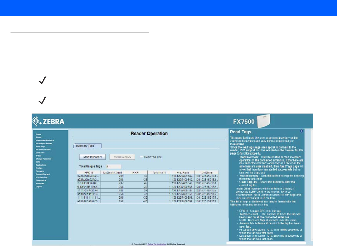
4 - 30 FX7500 RFID Reader Integrator Guide
Read Tags
Select Read Tags to view the Reader Operation window. Use this window to perform inventory on the connected
antennas and view the list of inventoried tags.
Figure 4-19
Read Tags Window
•
Start Inventory - Click to starts inventory operation on the connected antennas. If the there are no
connected antennas, no tags in the field of view, or all the antennas are user-disabled, the Read Tags
window indicates that inventory successfully started but no tags display.
•
Stop Inventory - Stops the ongoing inventory operation.
•
Clear Tag List - Clears the current tag list.
•
Total Unique Tags - Indicates the number of unique tags read.
The list of tags appears in a table with the following attributes for each tag:
•
EPC Id - Unique tag EPC ID.
•
TagSeen Count - Number of times the tag was identified on the specific antenna.
•
RSSI - Received Signal Strength Indication.
•
Antenna Id - Antenna ID on which the tag is seen.
•
FirstSeen time stamp - UTC time (in microseconds) when the tag was first seen.
•
LastSeen time stamp - UTC time (in microseconds) when the tag was last seen.
NOTE Enable Java JRE support on the browser in order for this window to function properly.
NOTE This page is not supported when LLRP is configured in secure mode.
Draft 2
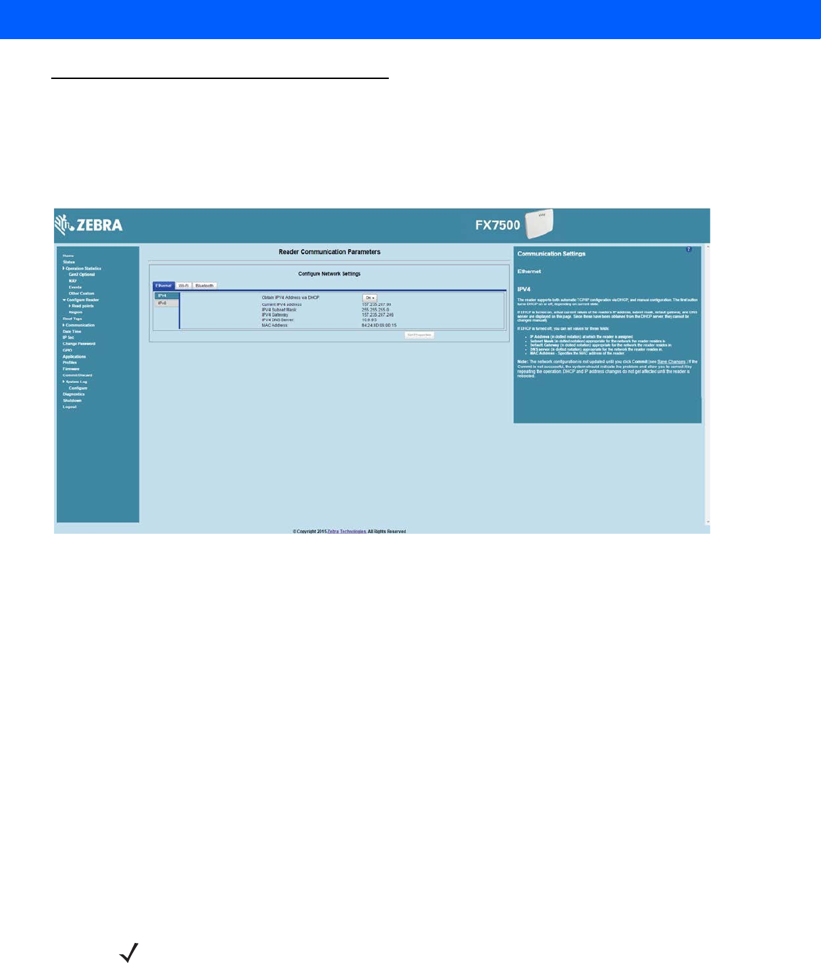
Administrator Console 4 - 31
Communication Settings
Select Communication to view the Configure Network Settings window. This window has tabs for Ethernet, WiFi,
and Bluetooth. Each tab has options for IPV4 and IPV6.
Configure Network Settings - Ethernet Tab
Figure 4-20
Configure Network Settings - Ethernet Tab
IPV4
•
Obtain IPV4 Address via DHCP - The reader supports both automatic TCP/IP configuration via DHCP
and manual configuration. The DHCP button turns DHCP on and off.
If DHCP is turned on, this window displays actual current values of the reader's IP address, subnet mask,
default gateway, and DNS server. Because these are obtained from the DHCP server, they cannot be
changed manually.
If DHCP is turned off, you can set the following values for these fields.
•
Current IPV4 Address - IP address (in dotted notation) at which the reader is assigned.
•
IPV4 Subnet Mask - Subnet mask (in dotted notation) appropriate for the network in which the reader
resides.
•
IPV4 Default Gateway - Default gateway (in dotted notation) appropriate for the network in which the
reader resides.
•
IPV4 DNS Server - DNS server (in dotted notation) appropriate for the network in which the reader
resides.
•
MAC Address - The MAC address of the reader.
NOTE You must click Commit to update the network configuration (see Save Changes.) If the Commit is not
successful, the system indicates the problem and allows correcting it by repeating the operation. DHCP
and IP address updates do apply until the reader is rebooted.
Draft 2
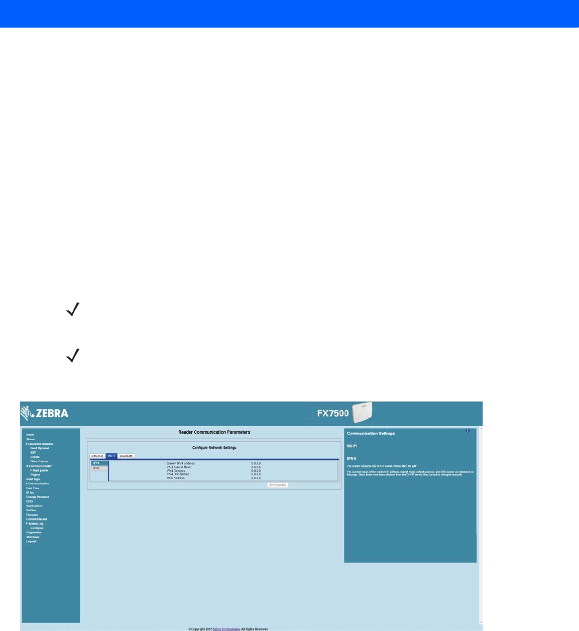
4 - 32 FX7500 RFID Reader Integrator Guide
IPV6
•
Obtain IPV6 Address via DHCP - The reader supports both automatic TCP/IPV6 configuration via
DHCP and manual configuration. The DHCP button turns DHCP on and off.
If DHCP is turned on, this window displays actual current values of the reader's IPV6 address, prefix
length, default gateway, and DNS server. Because these are obtained from the DHCP server, they
cannot be changed manually.
If DHCP is turned off, you can set the following values for these fields.
•
Current IPV6 Address - IP address (in dotted notation) at which the reader is assigned.
•
Prefix Length - Prefix length appropriate for the network in which the reader resides.
•
IPV6 Default Gateway - Default gateway (in dotted notation) appropriate for the network in which the
reader resides.
•
IPV6 DNS Server - DNS server (in dotted notation) appropriate for the network in which the reader
resides.
•
MAC Address - The MAC address of the reader.
Configure Network Settings - Wi-Fi Tab
Figure 4-21
Configure Network Settings - Wi-Fi Tab
IPV4
The reader supports only DHCP-based configuration for WIFI. This window displays the current values of the
reader's IP address, subnet mask, default gateway, and DNS server. Since these are obtained from the DHCP
server, they cannot be changed manually.
NOTE You must click Commit to update the network configuration (see Save Changes.) If the Commit is not
successful, the system indicates the problem and allows correcting it by repeating the operation. DHCP
and IP address updates do apply until the reader is rebooted.
NOTE Also enable automatic configuration for IPV6 through RA packets configuration. To enable or disable RA
packet configuration go to the Services window (see Services).
Draft 2
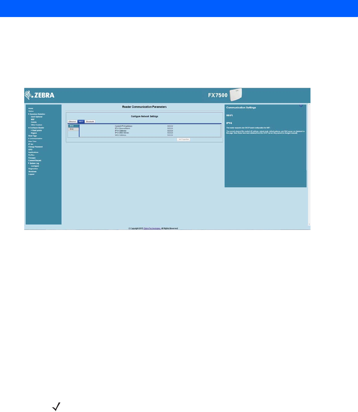
Administrator Console 4 - 33
IPV6
The reader supports only DHCP based configuration for WIFI. This window displays the current values of the
reader's IPV6 address, prefix length, default gateway, and DNS server. Since these are obtained from the
DHCP server, they cannot be changed manually.
Configure Network Settings - Bluetooth Tab
Figure 4-22
Configure Network Settings - Bluetooth Tab
The reader supports only automatic IP configuration of the Bluetooth interface.
If a Bluetooth client is connected to the reader, this window displays the current values of the reader's IPV4
address, Subnet mask, IPV6 address, and prefix length in the appropriate tabs. Because these are
automatically configured for a reader, they cannot be changed manually.
If a Bluetooth USB dongle is connected to the reader, you can set the following Bluetooth properties in this
window:
•
Discoverable - Select whether the reader is seen by other Bluetooth-enabled devices on discovery.
•
Pairable - Select whether any Bluetooth-enabled device can pair with reader.
•
Use Passkey - Enable this option to mandate the connecting device to supply a pre-determined passkey
to use for authentication while pairing.
•
Passkey - The passkey to use for authentication.
•
DHCP start address - The starting address of the DHCP IP range out of which an IP is assigned to the
connecting device.
•
DHCP end address - The end address of the DHCP IP range out of which an IP is assigned to the
connecting device.
NOTE The DHCP IP range specified using the DHCP start address and DHCP end address options also
determine the IP of the Bluetooth interface of the reader. The first two octets of the IP address of the
reader Bluetooth interface are taken from the IP range specified and the last two octets use the reader
BD address.
Draft 2
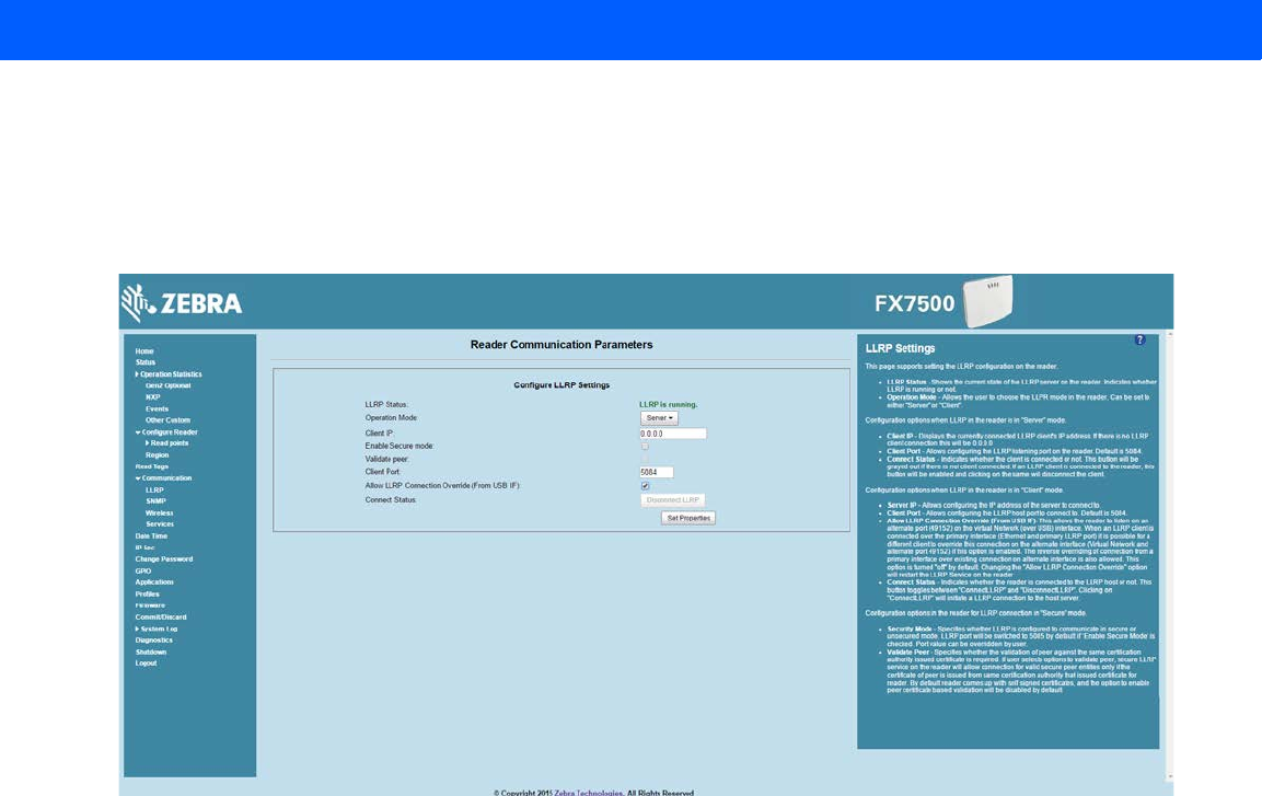
4 - 34 FX7500 RFID Reader Integrator Guide
Configure LLRP Settings
Select LLRP to view and set the LLRP settings. By default, LLRP activates in server mode, where LLRP clients
can connect to the reader using the port number specified in the Client port field. You can also configure the
reader in LLRP client mode. In this case, configure the LLRP server address in this web page as well. LLRP
cannot be disabled since it is the primary native protocol for RFID for the reader.
Figure 4-23
Configure LLRP Settings Window
This window offers the following fields:
•
LLRP Status - Displays the current state of the LLRP server on the reader. Indicates whether LLRP is
running.
•
Operation Mode - Sets the LLPR mode in the reader to either Server or Client.
LLRP configuration options when the reader is in Server mode:
•
Client IP - Displays the currently connected LLRP client's IP address. If there is no LLRP client
connection, this is 0.0.0.0.
•
Client Port - Configures the LLRP listening port on the reader. The default is 5084.
•
Connect Status - Indicates whether the client is connected. This button is grayed out if there is no client
connected. If an LLRP client is connected to the reader, this button is enabled; click this button to
disconnect the client.
LLRP configuration options when the reader is in Client mode:
•
Server IP - Configures the IP address of the server to connect to.
•
Client Port - Configures the LLRP host port to connect to. The default is 5084.
•
Allow LLRP Connection Override (From USB IF) - This allows the reader to listen on an alternate port
(49152) on the virtual network (over USB) interface. When an LLRP client is connected over the primary
interface (Ethernet and primary LLRP port), a different client can override this connection on the alternate
interface (Virtual Network and alternate port 49152) if this option is enabled. This also permits overriding
a connection from a primary interface over an existing connection on an alternate interface. This option is
off by default. Changing this option restarts the LLRP service on the reader.
Draft 2
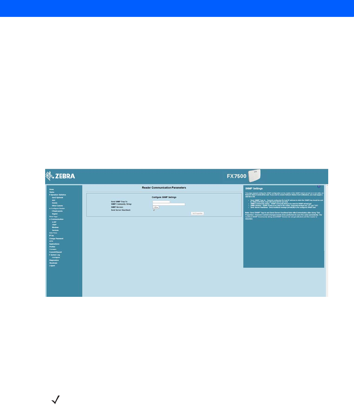
Administrator Console 4 - 35
•
Connect Status - Indicates whether the reader is connected to the LLRP host. This button toggles
between ConnectLLRP and DisconnectLLRP. Clicking ConnectLLRP initiates an LLRP connection to
the host server.
LLRP configuration options when the reader is in Secure mode:
•
Security Mode - Specifies whether LLRP communicates in secure or unsecure mode. Checking Enable
Secure Mode switches the LLRP port to 5085 by default. You can override the port value. LLRP in
secure mode supports ciphers that are compliant with TLS1.2.
•
Validate Peer - Specifies whether the validation of peer against the same certification authority issued
certificate is required. If you select the validate peer option, the secure LLRP service on the reader
allows connection for valid secure peer entities only if the certificate of the peer is issued from the same
certification authority that issued the certificate for the reader. By default the reader uses self-signed
certificates, and peer certificate based validation is disabled.
SNMP Settings
Select SNMP to view the Configure SNMP Settings window.
Figure 4-24
Configure SNMP Settings Window
Use this window to configure the SNMP host settings to allow sending network status events and receiving
network status event notifications:
•
Send SNMP Trap To - Configures the host IP address to which the SNMP trap is sent. Leave this blank to
send no traps to any host.
•
SNMP Community String - SNMP community string to use for SNMP set and get.
•
SNMP Version - SNMP version to use in the reader. Supported versions are V1 and V2c.
•
Send Server Heartbeat - Sends a heartbeat message periodically to the configured SNMP host.
NOTE Send SNMP Trap To and Send Server Heartbeat take effect immediately after clicking Set Properties.
However, perform a Commit to persist the changes. The modified SNMP Community String and SNMP
Version are not affected until the reader reboots.
Draft 2

4 - 36 FX7500 RFID Reader Integrator Guide
Wireless Settings
Select Wireless to view the Reader Wireless Settings Parameters window.
Figure 4-25
Wireless Settings Window
Use this window to set the wireless configuration on the reader. Zebra provides native support for USB WiFi
adapters with the Realtek chipset RTL 8187, and tested the following adapters:
•
Alfa AWUS036H
•
CCrane Versa Wifi USB Adapter II
The Wireless Settings window offers the following options:
•
Get Details - Click to get details of the connected network, including the ESSID, signal strength, and
connection status.
•
Disconnect - Click to disconnect from a connected network.
•
Scan and Choose Network - Scan the available networks. Clicking this lists the ESSID in the
drop-down menu. If the ESSID is hidden (not broadcasted), enter the ESSID in the text box provided.
•
Passkey - Pre-shared key for the WPA/WPA2 network.
•
Connect Automatically - Persist network setting across reboots and automatically retain association
with the configured AP.
NOTE The scan function can take several seconds. All buttons on the page are disabled while the scan is in
progress, and re-enabled when the scan completes.
Draft 2
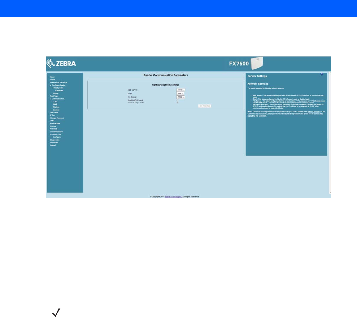
Administrator Console 4 - 37
Network Services Settings
Select Services to view the Configure Network Service Settings window.
Figure 4-26
Configure Network Service Settings Window
The reader supports the following network services.
•
Web Server - Configures the web server in either HTTP (unsecure) or HTTPS (secure) mode.
•
Shell - Sets the shell to SSH (secure) mode or a disabled state.
•
File Server - Sets the file server to either FTP (unsecure) or FTPS (secure) mode.
•
Disable IPV6 Stack - Select this to disable the reader's IPV6 stack.
•
Receive RA packets - This option is only valid when the IPV6 stack is enabled. Enable this to allow IPV6
IP configuration through RA packets; otherwise obtain the IP via DHCP in the Communication window or
assign statically.
NOTE You must click Commit to update the service configuration (see Save Changes.) If the Commit is not
successful, the system indicates the problem and allows correcting it by repeating the operation.
Draft 2
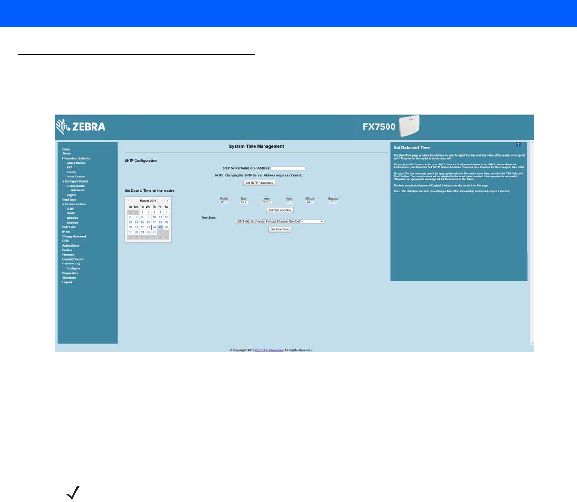
4 - 38 FX7500 RFID Reader Integrator Guide
System Time Management
Select Date Time to view the System Time Management window. Use this window to set the date and time value
of the reader, or to specify an NTP server for the reader to synchronize with.
Figure 4-27
System Time Management Window
To specify an SNTP server, enter the SNTP server's IP address or name in the SNTP Server Name or IP
Address box, and then click Set SNTP Parameters. You must select Commit for the change to take effect.
To adjust the time manually, select the appropriate value for the user's local time, and click the Set Date and
Time button. This adjusts the reader's clock to the value provided if the operation is successful. Otherwise, an
appropriate message indicates the reason for the failure.
You can also set the Time Zone (including use of Daylight Savings) using the drop-down menu.
NOTE The date/time and time zone changes take effect immediately, and do not require a Commit.
Draft 2
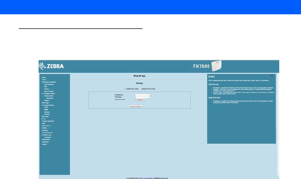
Administrator Console 4 - 39
IPV6 IP Sec
Select IP Sec to view the IPV6 IP Sec window. IP Sec settings allow adding IPSec pairing of the reader with a
partner with a pre-shared key.
Figure 4-28
IPV6 IP Sec Window
To add an IP Sec entry:
1. Click the Add IP Sec Entry radio button.
2. In the IP Address field, specify the IP address of the partner with whom the IP SEC communication is
intended.
3. In the Passkey field, enter the pre-shared passkey (from 6 to 15 characters) to use with the partner IP
address.
4. In the Access Level drop-down list, select the IPSec access level. Options are Transport and Tunnel
mode. Currently the reader only supports Transport mode.
5. Click the Add IP Sec Entry button.
To delete an IP Sec entry:
1. Click Delete IP Sec Entry radio button.
2. In the IP Address field, specify the IP address of the partner with whom the IP SEC communication is
configured and is to be deleted.
3. Click the Delete IP Sec Entry button.
Draft 2
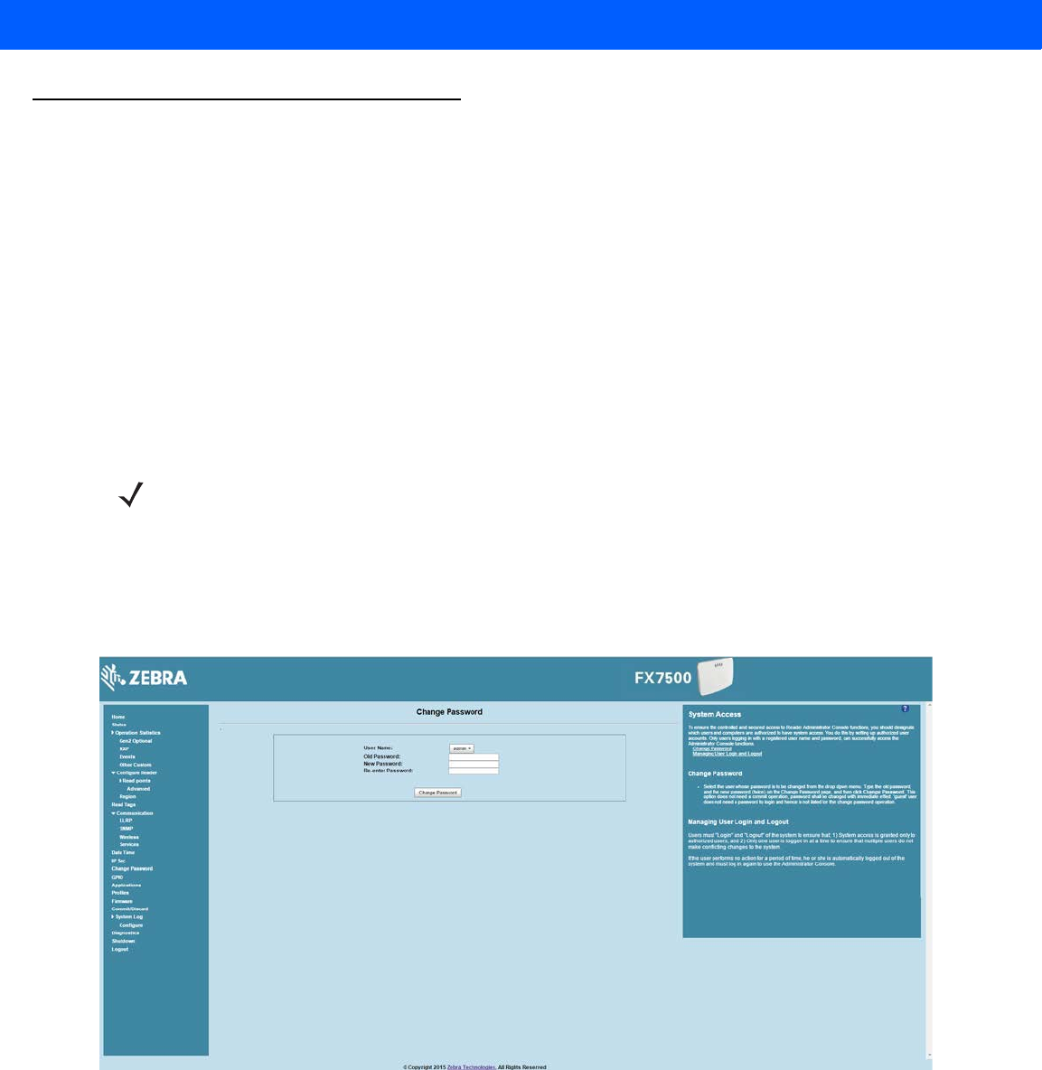
4 - 40 FX7500 RFID Reader Integrator Guide
Change Password
To ensure the controlled and secured access to reader Administrator Console functions, designate which users
and computers are authorized to have system access by setting up authorized user accounts. Only users
logging in with a registered user name and password can successfully access Administrator Console functions.
FX7500 User Accounts
The FX7500 supports the different user accounts:
•
admin - This user has web access but no shell access, with full privileges to make changes on the
reader using the Administrator Console interface and to access to the reader using the FTP interface.
•
guest - This user has web access but no shell access, with read-only privileges in the Administrator
Console and can not make configuration changes. The guest user does not need a password to log in to
the Administrator Console.
•
rfidadm - This is the reader administrator, with shell access but no Administrator Console access.
rfidadm has full access to the /apps directory and read-only access to most of the other directories,
including the /platform, /usr, /lib, /etc, and /bin directories. The rfidadm user can use this account to
install and uninstall RFID programs and upload user applications.
Select Change Password to view the Change Password window.
Figure 4-29
Change Password Window
To set a user password:
1. In the User Name drop-down list, select the user for whom to change the password.
2. In the Old Password field, enter the existing password for that user.
3. In the New Password field, enter the new password, and again in the Re-Enter Password field.
4. Click Change Password. The password changes immediately and does not require a Commit operation.
NOTE The Change Password function is not supported for the user guest.
Draft 2
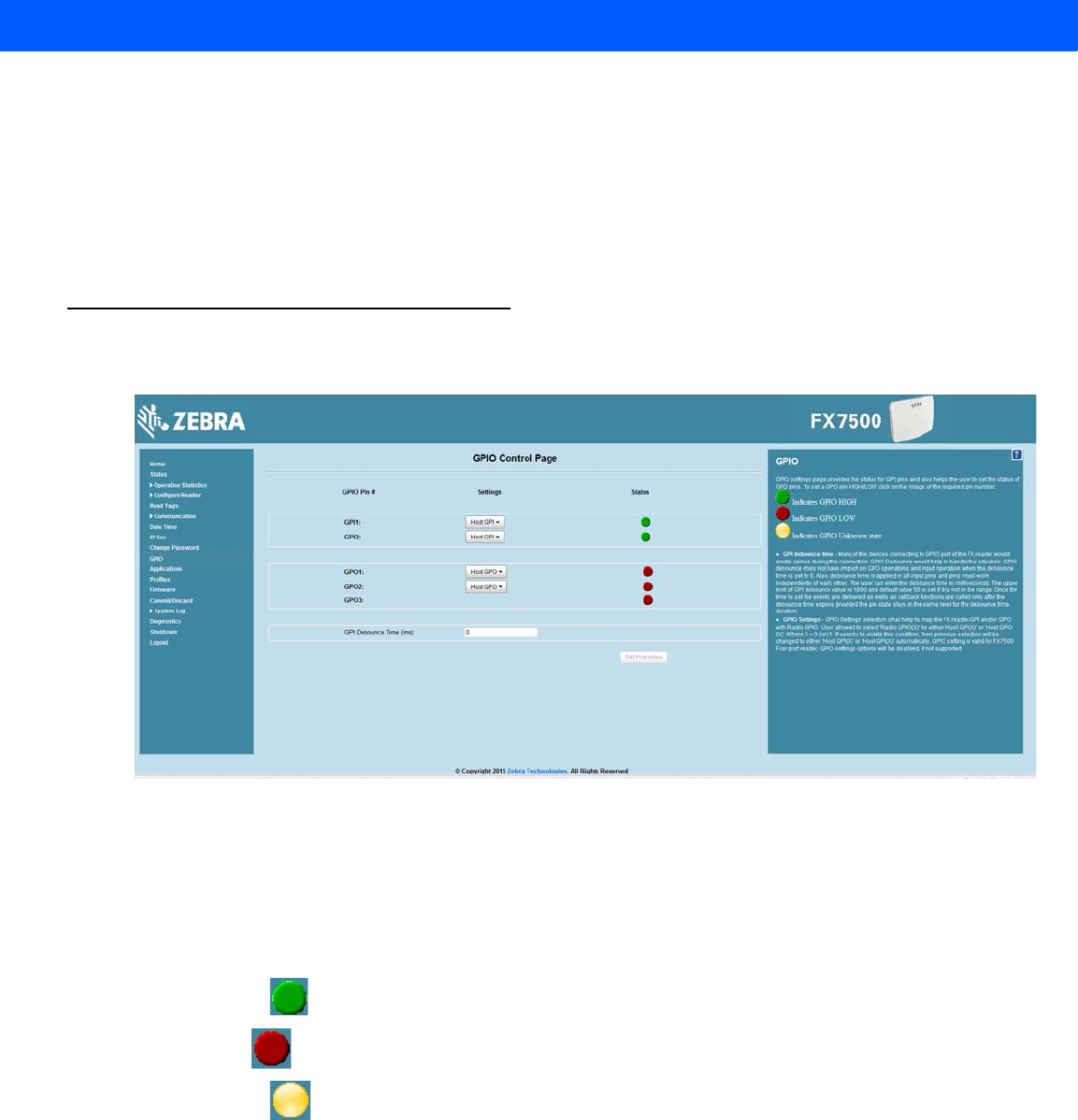
Administrator Console 4 - 41
Managing User Login and Logout
Users must log in and log out of the system to ensure that system access is granted only to authorized users,
and that only one user is logged in at a time to ensure that multiple users do not make conflicting changes to
the system.
If the user performs no action for a period of time, the system automatically logs him or her out. The user must
log in again to use the Administrator Console.
GPIO
Select GPIO to view the GPIO Control Page. This window allows viewing and setting the status for GPI pins.
Figure 4-30
GPIO Control Page
•
Settings - Map the reader GPI and/or GPO with the radio GPIO. Select either Radio or Host for GPIx or
GPOx where x = 0 or 1. An attempt to violate this condition changes the selection to either Host GPIx or
Host GPOx automatically. These settings are valid for FX7500 four port readers and are disabled if not
supported.
•
Status - To set a GPO pin high or low, click on the image next to the required pin number:
•Green indicates GPIO HIGH
•Red indicates GPIO LOW
•Yellow indicates GPIO unknown
•
GPI Debounce Time - Enter a value of up to 1000 milliseconds to minimize spikes that can occur when
a device connects to the GPIO port of the FX reader. The default is 50. Debounce time applies to all input
pins, and pins must work independently of each other. Events and callback functions occur only after the
debounce time expires, provided the pin state remains at the same level for the debounce time duration.
GPIO debounce does not impact GPO and input operations when set to 0.
•
Set Properties - Click this when all selections are made.
Draft 2
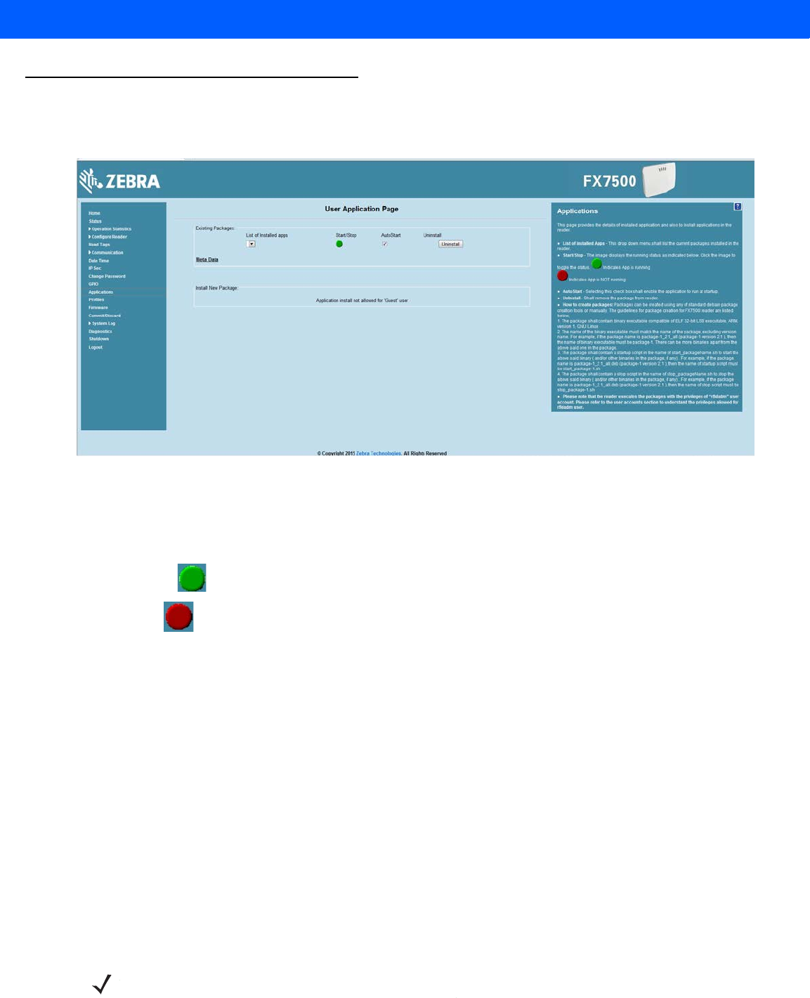
4 - 42 FX7500 RFID Reader Integrator Guide
Applications
Select Applications to view the User Application Page. This window allows installing applications on the
reader and provides details of the installed application.
Figure 4-31
User Application Page
The Existing Packages section includes the following options:
•
List of Installed apps - The drop-down menu lists the current packages installed in the reader.
•
Start/Stop - The image displays the running status as follows. Click the image to toggle the status.
•Green indicates application is running
•Red indicates application is not running
•
AutoStart - Select this check box to run the application at startup.
•
Uninstall - Removes the package from the reader.
To create packages for the FX7500 reader, use any of the standard Debian package creation tools, or create
them manually. The FX7500 Embedded SDK Programmers Guide provides details on creating application
packages to install on the reader.
•
The package must contain a binary executable compatible with ELF 32-bit LSB executable, ARM,
version 1, GNU Linux.
•
The name of the binary executable must match the name of the package, excluding the version name.
For example, if the package name is package-1_2.1_all (package 1 version 2.1), the name of the
binary executable must be package-1. There can be more than one binary in the package.
•
The package must contain a startup script in the name of start_packageName.sh to start the binary or
binaries in the package. For example, if the package name is package-1_2.1_all.deb (package 1
version 2.1), the name of the startup script must be start_package-1.sh.
•
The package must contain a stop script in the name of stop_packageName.sh to stop the binary or
binaries in the package. For example, if the package name is package-1_2.1_all.deb (package 1
version 2.1), the name of stop script must be stop_package-1.sh.
NOTE The reader executes the packages with the privileges of rfidadm user account. See the user accounts
section for information on rfidadm user privileges.
Draft 2
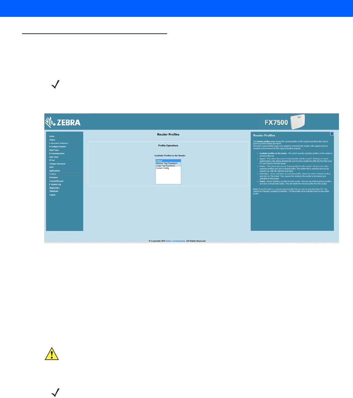
Administrator Console 4 - 43
Reader Profiles
Select Profiles in the selection menu to view the Reader Profiles window, which shows the current profiles on
the reader and allows performing profile-related operations.
The window displays a set of provided configuration files, or profiles, that a user can re-use and/or modify
depending on the reader application or use case. The profiles serve as configuration examples.
Figure 4-32
Reader Profiles Window
The Reader Profiles window functions are:
•
Available Profiles in the Reader - Displays the available reader profiles.
•
Import - Click to open a file dialog and pick a profile (XML file) from the local PC and import it into the
reader.
•
Export - Select an available profile and click Export to export profile information and save an XML file
onto the local drive.
•
Set Active - Activates a selected profile. Select an available profile and click Set Active to load the profile
content in the reader.
•
Delete - Select an available profile and click Delete to delete the profile.
Profiles can specify a number of reader parameters, including RF air link profiles. Air link profiles cannot be
configured using LLRP or web page interface. See Appendix C, RF Air Link Configuration for more information
about air link profile configuration.
NOTE Because the Reader Profiles window uses an applet to connect to the reader, enable JVM support on
the browser in order for this window to function properly.
CAUTION Swapping profiles between readers using static IP addresses is not recommended. Activating a profile
with a static IP address changes the IP of the reader, and if not done properly can make the reader
inaccessible.
NOTE Current Config is a special logical profile that can only be exported to the PC. This cannot be imported,
activated, or deleted. Only the profile name indicates that it is the active profile.
Draft 2

4 - 44 FX7500 RFID Reader Integrator Guide
FIPS Support on FX7500
The FX7500 supports FIPS 140-2 Level 1 for the following interfaces:
•
HTTPS
•
FTPS
•
SSH
•
LLRP Server
•
IPSec
To enable or disable FIPS support in the reader profile, export the profile XML (CurrentConfig) from the
reader and set FIPS_MODE_ENABLED to 1 to enable FIPS, or 0 to disable FIPS. Then import the XML to the
reader and activate. Changing the FIPS mode restarts the reader. By default, FIPS is disabled.
Firmware Version/Update
The Firmware Version window displays the current software and firmware versions and allows upgrading to
new firmware. From the selection menu, click Firmware.
Figure 4-33
Firmware Version
Current Version indicates the binary versions currently running in the reader. Last Known Version indicates
binary image versions stored in the backup partition. This window provides version information on the following
firmware:
•
Boot Loader
•
OS
•
File System
•
Reader Application
•
LLRP
•
Radio Firmware
•
Radio API
Select Revert Back to revert the firmware to last known version. The reader automatically reboots. This option
is not enabled if the reader detects an error in the previous firmware update.
Draft 2

Administrator Console 4 - 45
Firmware Update
The Firmware Update window allows upgrading to new firmware. From the selection menu, click Update.
The reader supports three different methods of updating the firmware:
•
Update using a USB drive.
•
File-based update that allows uploading the firmware files from the PC (or a network location) to the
reader and running the update.
•
FTP / FTPS / SCP server-based update.
For instructions on updating the firmware, see Chapter 7, Firmware Upgrade.
Commit/Discard
Changes made to the logical view of the reader network using the Administrator Console do not immediately
apply to the reader and network connections. To apply reader configuration modifications, select
Commit/Discard, then click Commit to save the changes to the reader configuration file, and to update the
running physical reader network. While a successful update can take up to a minute to complete, the system
continues to operate with a brief one or two second pause.
Figure 4-34
Commit/Discard Window
To discard changes to the server's configuration file made to the reader network during this session, click
Discard.
Click Factory Reset to reset the reader to factory defaults. This clears all customized user settings, including
configuration, and installed applications. The reader reboots automatically.
NOTE You must be logged in with Administrator privileges in order to access this window. See Change
Password on page 4-40.
Draft 2
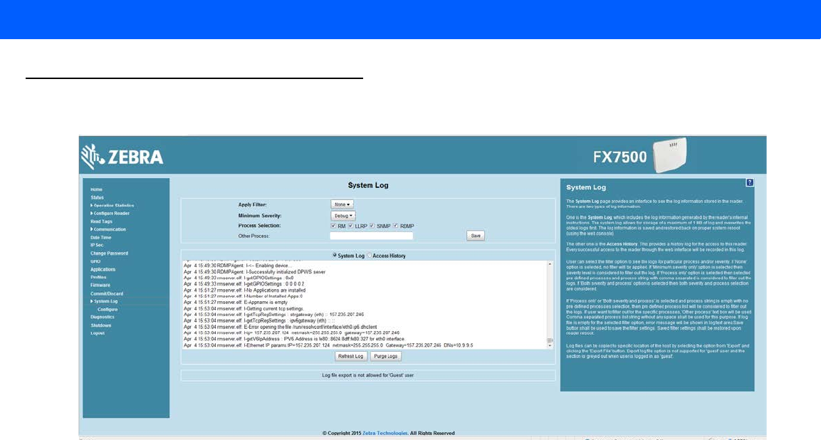
4 - 46 FX7500 RFID Reader Integrator Guide
System Log
The System Log window lists reader log information.
Figure 4-35
System Log Window
This window offers the following options:
•
Apply Filter - Select a filter option from the drop-down menu to view logs for particular process and/or
severity:
• None - Do not apply a filter.
• Minimum Severity only - The severity level filters the log.
• Process Selection only - Selected pre-defined processes and comma-separated process strings
filters the logs.
• Minimum Severity & Process Selection - both severity and process selection are considered in the
filter.
If you select Process Selection only or Minimum Severity & Process Selection and the process
string is empty with no pre-defined process selection, then the pre-defined process list filters the logs.
•
Minimum Severity - Select the severity level on which to filter.
•
Process Selection - Select the types of processes to filter upon.
•
Other process - To filter for specific processes, enter the process in this text box using a
comma-separated process list string with no spaces. If the log file is empty for the selected filter option,
an error message appears in the log text area. Click Save to save the filter settings, which persist upon
reader reboot.
•
Log area - Select a radio button for one of the two types of log information offered:
•System Log - Includes the log information generated by the reader internal instructions. This stores up
to 1 MB of log information, and overwrites the oldest logs first. The log information is saved and
restored on proper system reboot (via the Administrator Console).
•Access History - Provides a history log for reader access, including every successful access to the
reader through the Administrator Console.
•
Select the Refresh Log to refresh the information in the log, or Purge Logs to clear the information.
•
To copy the log file to a specific location on the host select an option from the Export drop-down. Enter
the location in the File Path field, then select the Export File button.
Draft 2
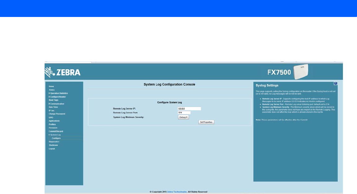
Administrator Console 4 - 47
Configure System Log
This window configures system log settings. If the system log host is not set (or is not valid), log messages are
not sent.
Figure 4-36
Configure System Log Window
This window offers the following options:
•
Remote Log Server IP - Configures the host IP address to which log messages are sent. IP address
0.0.0.0 indicates that no host is configured.
•
Remote Log Server Port - Remote log server listening port. The default port is 514.
•
System Log Minimum Severity - The minimum severity above which data is stored in the log file. This
option does not impact remote logging or the logs already stored in the log file.
You must select Commit to activate these settings.
Draft 2
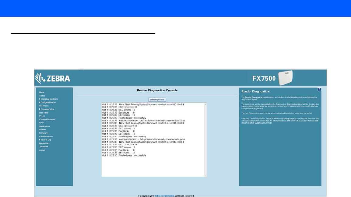
4 - 48 FX7500 RFID Reader Integrator Guide
Reader Diagnostics
Select Diagnostics to view the Reader Diagnostics window, which allows running diagnostics and viewing
the diagnostics report.
Figure 4-37
Reader Diagnostics Window
Selecting Start Diagnostics clears the system log and displays the diagnostics report. The reader reboots
when the diagnostics completes. Return to the Diagnostics window to view the diagnostics report.
To export the diagnostics report to a file, on the System Log window, select Process Selection only in Apply
Filter, de-select all other processes, and in the Other Process text box enter:
rmserver.elf: N-D,llrpserver.elf: N-D
Draft 2
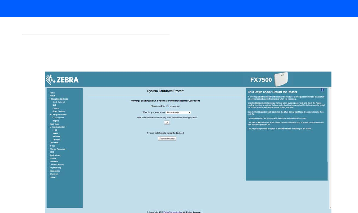
Administrator Console 4 - 49
Shutdown
To protect the integrity of the reader data, gracefully reboot the reader via the Administrator Console when
necessary.
Figure 4-38
System Shutdown/Restart Window
To shut down or restart the reader:
1. Click the Shutdown link to display the System Shutdown/Restart window.
2. Check the Please Confirm check box to accept the system shut down and/or restart the system (this may
interrupt normal system operation).
3. Select one of the following options from the What do you want to do drop-down list:
•
Restart Reader - saves the user data and then restarts.
•
Shut down Reader server - the reader saves the user data, stops all reader functions, and waits to be
powered off.
4. Click Go.
This window also provides an option to enable or disable the reader watchdog.
Draft 2

4 - 50 FX7500 RFID Reader Integrator Guide
Draft 2
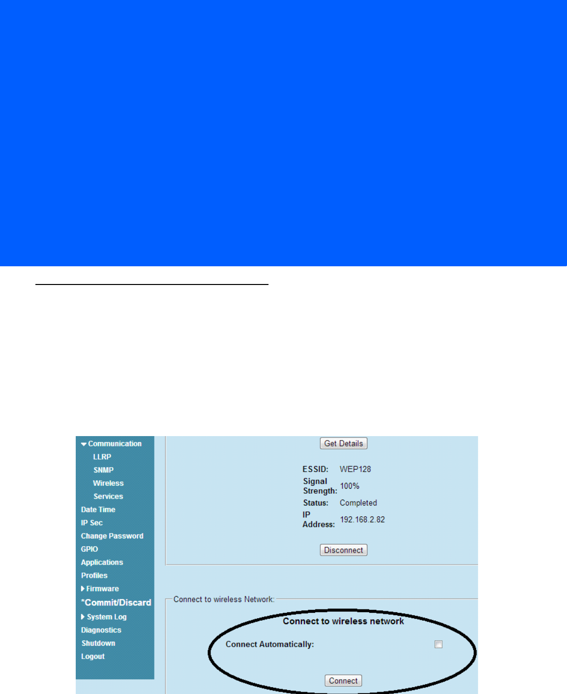
CHAPTER 5 WI-FI CONFIGURATION
Wireless Network Advanced Configuration
FX7500 uses the wpa_supplicant application to connect with wireless networks. Advanced users can place
their own configuration file in the /apps folder to connect to wireless networks. This configuration file is
wpa_supplicant.conf. The parameters of this file are well documented in the public domain. Refer to
http://linux.die.net/man/5/wpa_supplicant.conf for the most commonly used parameters and
http://www.daemon-systems.org/man/wpa_supplicant.conf.5.html for all available parameters. Also see
Appendix E, Copying Files To and From the Reader for instructions on copying files to /apps directory.
If /apps/wpa_supplicant.conf is present in the reader, the reader uses this file to connect to a wireless
network. This supersedes the configuration in the Administrator Console, which changes to reflect the
custom configuration file.
Figure 5-1
Administrator Console Update
Draft 2

5 - 2 FX7500 RFID Reader Integrator Guide
Note that there are no text boxes in the user interface for ESSID and password. The console obtains these
directly from the custom configuration file.
Sample Configuration Files
Wireless network with WPA2 encryption type (AP name is "DEV"):
ctrl_interface=/var/run/wpa_supplicant
ctrl_interface_group=0
ap_scan=1
network={
ssid="DEV"
proto=RSN WPA
key_mgmt=WPA-PSK
pairwise=CCMP TKIP
group=CCMP TKIP
psk="my secret password"
}
Open wireless network (AP Name is DEV_Open):
ctrl_interface=/var/run/wpa_supplicant
ctrl_interface_group=0
ap_scan=1
network={
ssid="DEV_Open"
key_mgmt=NONE
}
Wireless network with WEP encryption type (AP Name is WEP128):
ctrl_interface=/var/run/wpa_supplicant
ctrl_interface_group=0
ap_scan=1
network={
ssid="WEP128"
key_mgmt=NONE
wep_key0= "my secret password "
wep_tx_keyidx=0
priority=5
}
Draft 2

Wi-Fi Configuration 5 - 3
Configuration file with multiple network blocks:
# Simple case: WPA-PSK, PSK as an ASCII passphrase, allow all valid ciphers
network={
ssid="RFID_TNV"
psk="123456789"
priority=1
}
network={
ssid="RFID_TNV_WPA/WPA2"
psk="123456789"
priority=2
}
Refer to http://linux.die.net/man/5/wpa_supplicant.conf for further examples.
Draft 2
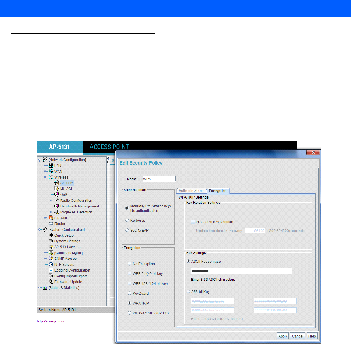
5 - 4 FX7500 RFID Reader Integrator Guide
Preferred Configurations for Access Points
The FX7500 reader supports WPA/WPA2 (http://en.wikipedia.org/wiki/Wi-Fi_Protected_Access) and also
WEP128 (http://en.wikipedia.org/wiki/Wired_Equivalent_Privacy) by default over the Administrator Console.
Other supported protocols are explained in previous sections. This section provides details on the preferred
configurations for access points.
AP: Zebra AP 5131
Network Type: WPA/TKIP
Figure 5-2
AP 5131, WPA/TKIP
Create a security policy WPA and select WPA/TKIP from the Encryption menu. Enter an ASCII password
between 8 and 63 characters or 64 hex characters. Select Apply and associate the ESSID with a security
policy.
Draft 2
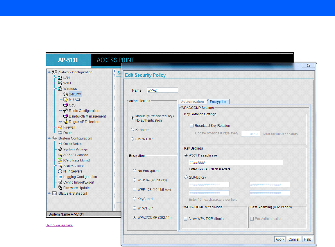
Wi-Fi Configuration 5 - 5
Network Type: WPA2/CCMP
Figure 5-3
AP 5131, WPA2/CCMP
Create a security policy WPA2 and select WPA/TKIP from the Encryption menu. Enter an ASCII password
between 8 and 63 characters or 64 hex characters. Select Apply and associate the ESSID with a security
policy.
Draft 2
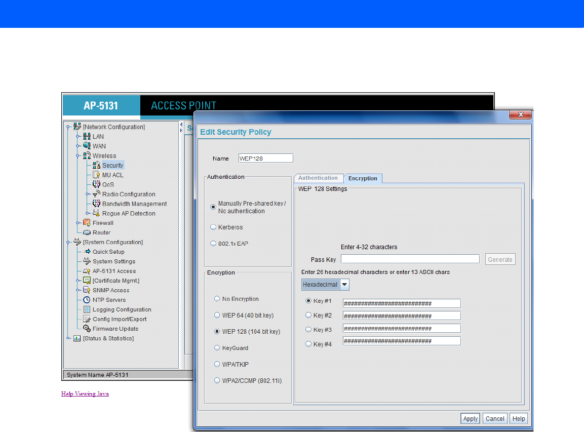
5 - 6 FX7500 RFID Reader Integrator Guide
Network Type: WEP128
Figure 5-4
AP 5131, WEP128
Create a security policy WEP128 and select WEP from the Encryption menu. Enter an ASCII password
between 13 characters or HEX password of 26 characters. Select Apply and associate the ESSID with a
security policy.
Draft 2
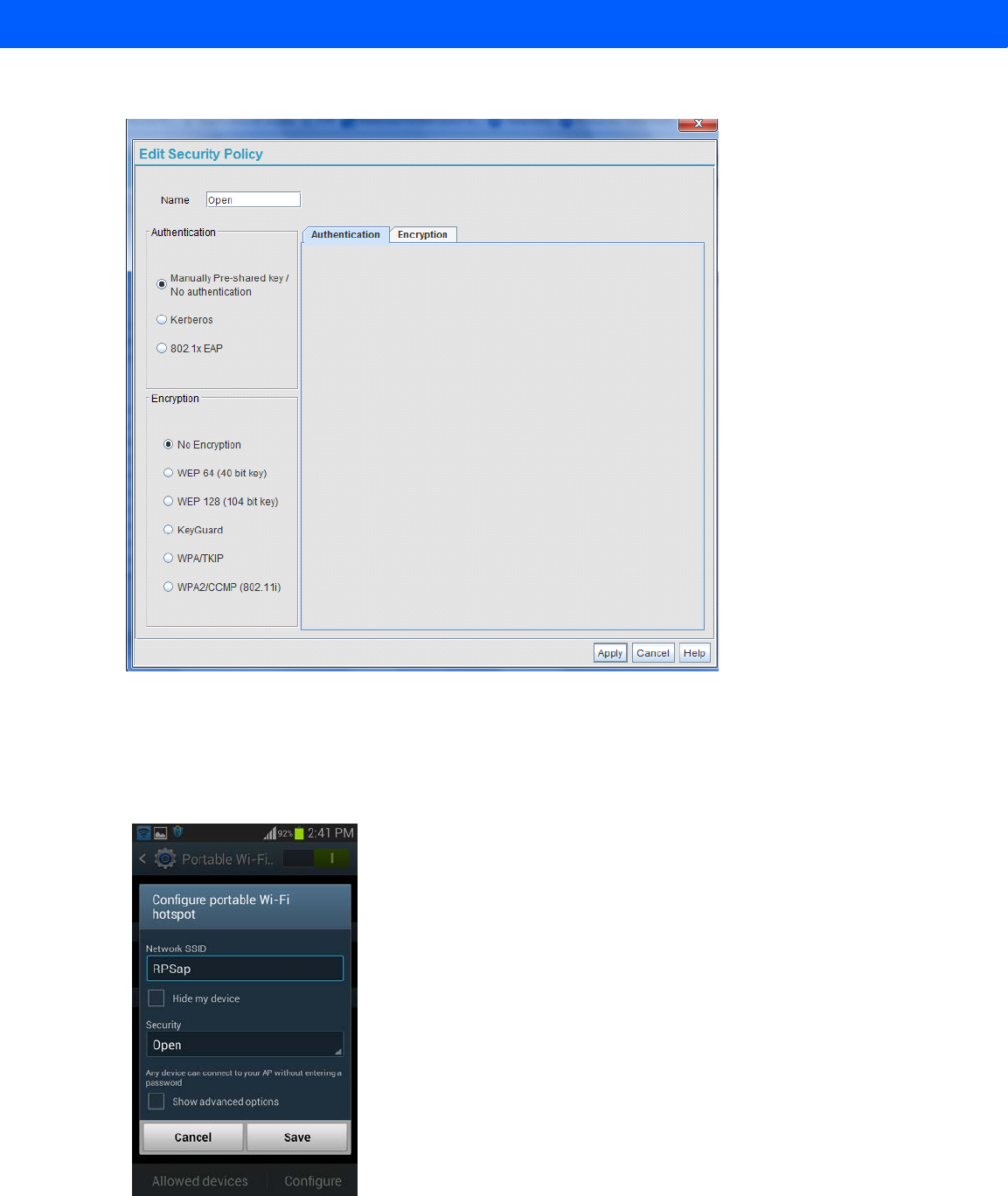
Wi-Fi Configuration 5 - 7
Open Network
Figure 5-5
Open Network
AP: Android Device
Enable the wireless tethering from the settings menu.
Open Network
Figure 5-6
Android Device, Open Network
Select Open from the Security drop-down menu and select Save.
Draft 2
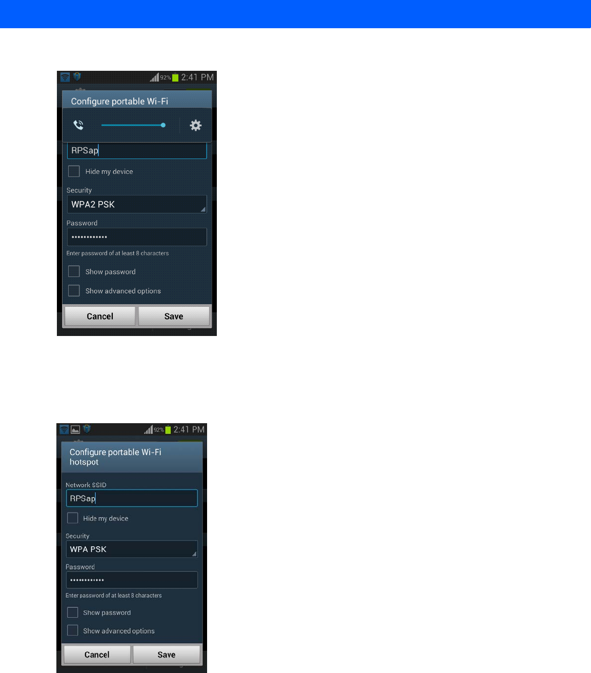
5 - 8 FX7500 RFID Reader Integrator Guide
Network Type: WPA2 PSK
Figure 5-7
Android Device, WPA2 PSK
Select WPA2PSK from the Security drop-down menu and enter a password. Select Save to start the wireless
hotspot.
WPA PSK
Figure 5-8
Android Device, WPA PSK
Select WPA PSK from the Security drop-down menu and enter a password. Select Save to start the wireless
hotspot.
Draft 2
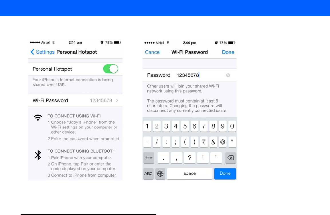

5 - 10 FX7500 RFID Reader Integrator Guide
Draft 2

CHAPTER 6 APPLICATION DEVELOPMENT
Introduction
The primary communication to the Zebra FX7500 RFID reader is via the LLRP protocol interface on TCP port
5084. There are two ways to develop applications for the reader:
•
Using the RFID3 API set included in the Zebra RFID SDK. The FX7500 reader supports host-based and
embedded RFID3 APIs.
•Java, C SDK support via the Eclipse IDE for host-based and embedded applications.
•Microsoft .Net support via the Visual Studio 2005/2008 IDE for host-based applications only.
•
Using the LLRP interface directly. Users can either use open source LLRP stacks, or develop their own
LLRP stacks. The FX7500 supports host-based and embedded applications.
Reference Guides
The following resources can be found on http://www.zebra.com/support:
•
FX Series Reader Software Interface Control Guide, p/n 72E-131718-xx
•
Programmer’s Guide provided with the Zebra RFID SDK. This introductory guide describes how to
perform various functions using the RFID3 API set.
•
FX7500 Embedded SDK Installation Guide provided with the Zebra RFID SDK.
•
FX7500 Embedded SDK Programmers Guide provides instructions on creating new embedded
applications.
•
Related Documents and Software on page xi for more documentation regarding RFID API and
application development.
Draft 2

6 - 2 FX7500 RFID Reader Integrator Guide
Draft 2

CHAPTER 7 FIRMWARE UPGRADE
Introduction
This chapter provides reader firmware update information on using the web-based Administrator Console. The
following methods are available to update the firmware on the FX7500 reader.
•
Update using a USB drive.
•
File-based update that allows uploading the firmware files from the PC (or a network location) to the
reader and running the update.
•
FTP / FTPS / SCP server-based update.
Use this procedure to update the following software components:
•
uboot
•
OS
•
Reader Server Application (includes Radio API and Radio firmware)
Prerequisites
The following items are required to perform the update:
•
Reader with power supply or POE connection
•
Laptop (or other host computer)
•
An Ethernet cable
•
An FTP server
•
Current firmware file examples:
•OSUpdate.elf
•response.txt
•u-boot_X.X.X.X.bin (uBoot, X.X.X.X is a filename version)
•uImage_ X.X.X.X (OS, X.X.X.X is a filename variable)
•rootfs_ X.X.X.X.jffs2 (Root FileSystem, X.X.X.X is a filename variable)
•platform_ X.X.X.X.tar.gz (Platform partition, X.X.X.X is a filename variable)
Refer to the release notes to determine which files were updated; not all of the files are updated in every
release.
Draft 2

7 - 2 FX7500 RFID Reader Integrator Guide
Failsafe Update
FX7500 provides true failsafe firmware update. Each partition (such as OS and platform) has an active and
backup partition.
The firmware update process always writes the new images to the backup partition. This ensures that any
power or network outages in the middle of firmware update does not prevent the reader from being operational.
In the case of a firmware update failure, the power LED on the reader lights red.
Update Phases
The firmware update takes place in three phases:
•
Phase 1 - The reader application retrieves the response.txt and OSUpdate.elf files from the ftp server.
•
Phase 2 - The reader application shuts down and the OSUpdate starts. The files referenced in the
response.txt file are retrieved from the FTP server and written to flash.
•
Phase 3 - The reader resets after all partitions update successfully. It may also update the RFID firmware
if it detects a different version in the platform partition.
A typical entry in the Response.txt is:
;platform partition
-t5 -fplatform_1.1.15.0.tar.gz -s8004561 -u8130879
The -t parameter is the file type, -f is the name of the file, and -s the size. Ensure the file size is correct.
";" comments out the rest of the line.
NOTE The Application Server, Radio API, and Radio firmware code all reside in the Platform partition.
Draft 2
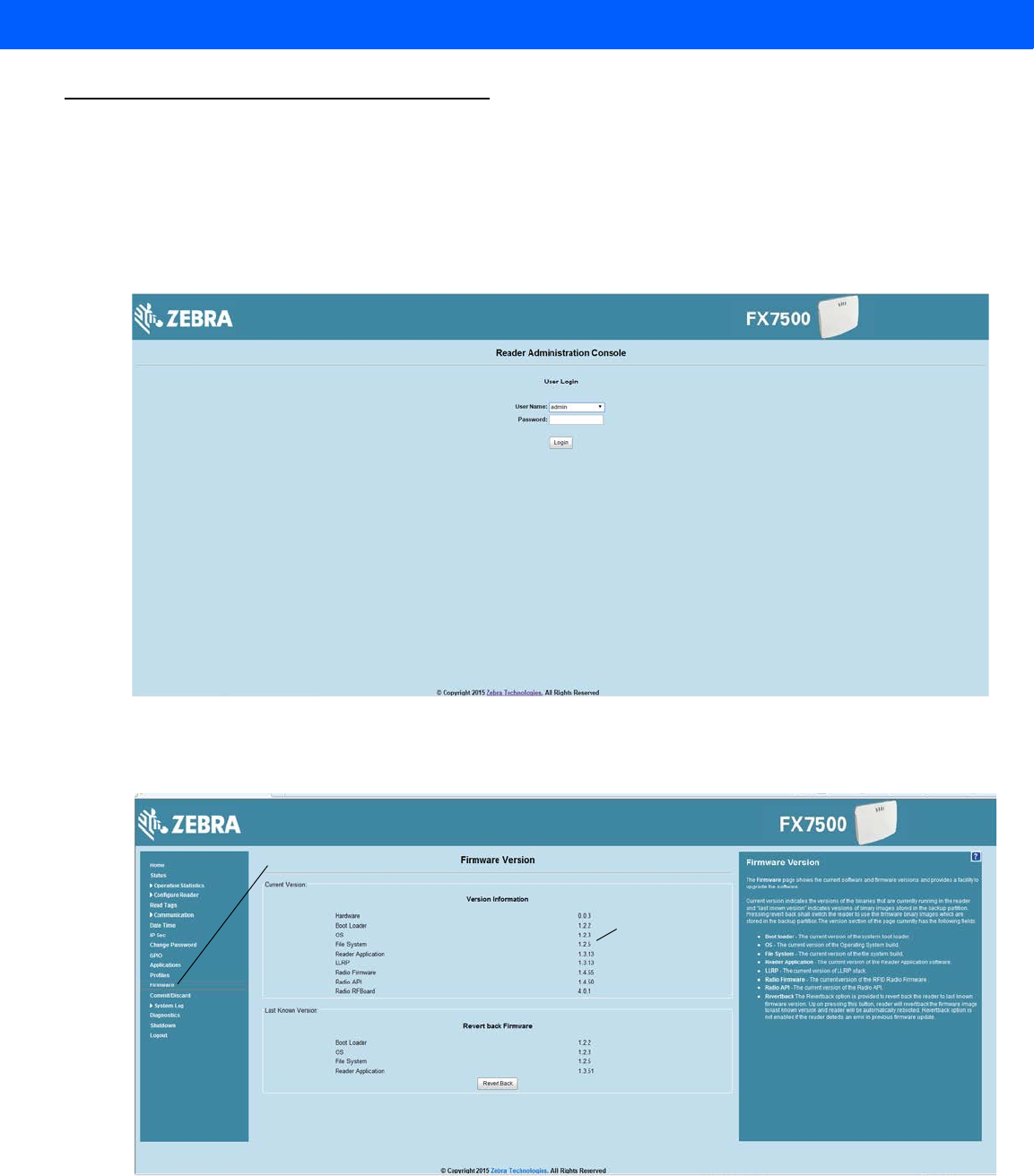
Firmware Upgrade 7 - 3
Updating FX7500 Reader Software
Verifying Firmware Version
To verify that the FX7500 reader firmware is outdated:
1. Log into the reader. In the User Login window, enter admin in the User Name: field and enter change in the
Password: field.
Figure 7-1
User Login Window
2. Select Firmware on the left side panel to verify that the current version of reader software is outdated,
e.g., 1.1.66.
Figure 7-2
Firmware Version Window
Firmware option
Version
number
Draft 2
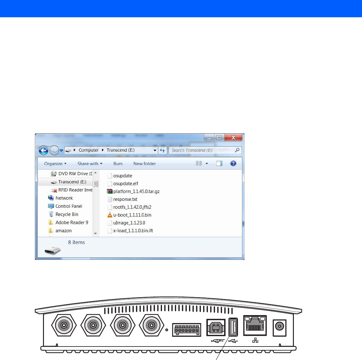
7 - 4 FX7500 RFID Reader Integrator Guide
Updating Methods
Download the reader update files from http://www.zebra.com/support:, then use one of three methods to
update the reader software to a later version, e.g., 1.1.45.0 or higher:
•
Update Using a USB Drive (Recommended)
•
File-Based Update on page 7-6
•
FTP-Based Update on page 7-8
Update Using a USB Drive (Recommended)
1. Copy all reader update files into the root folder of the USB drive.
Figure 7-3
USB Drive Root Folder
2. Insert the USB drive into the USB host port of the FX7500 RFID reader.
Figure 7-4
USB Host Port Window
Port 1 Port 2 Port 3 Port 4 GPIO 24 VDC
USB Host Port
Draft 2
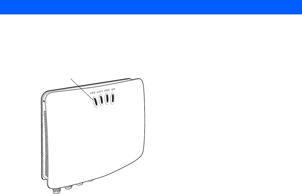
Firmware Upgrade 7 - 5
The reader starts the update process in 5 - 7 seconds, and indicates progress as follows:
•The reader continuously blinks the Power LED red.
•The reader blinks all four LEDs orange once.
•The reader Power LED remains steady orange.
•The reader Power LED settles to a steady green to indicate that the update is complete.
Figure 7-5
Reader LEDs
Power LED
Draft 2
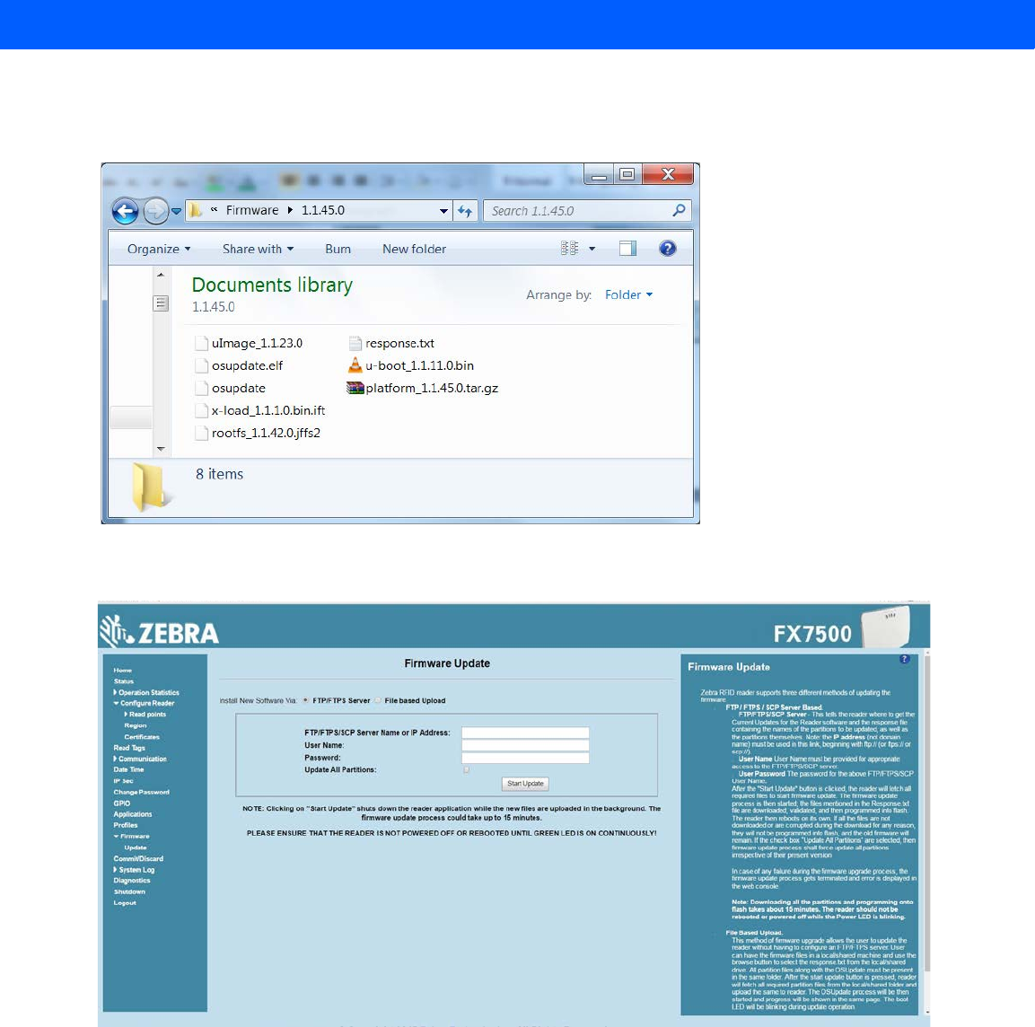
7 - 6 FX7500 RFID Reader Integrator Guide
File-Based Update
1. Copy all reader update files into any folder on a host computer.
Figure 7-6
Host Computer Folder
2. Log into the reader and navigate to the Firmware Update page.
Figure 7-7
Firmware Update Window
3. Select File based Upload.
Draft 2
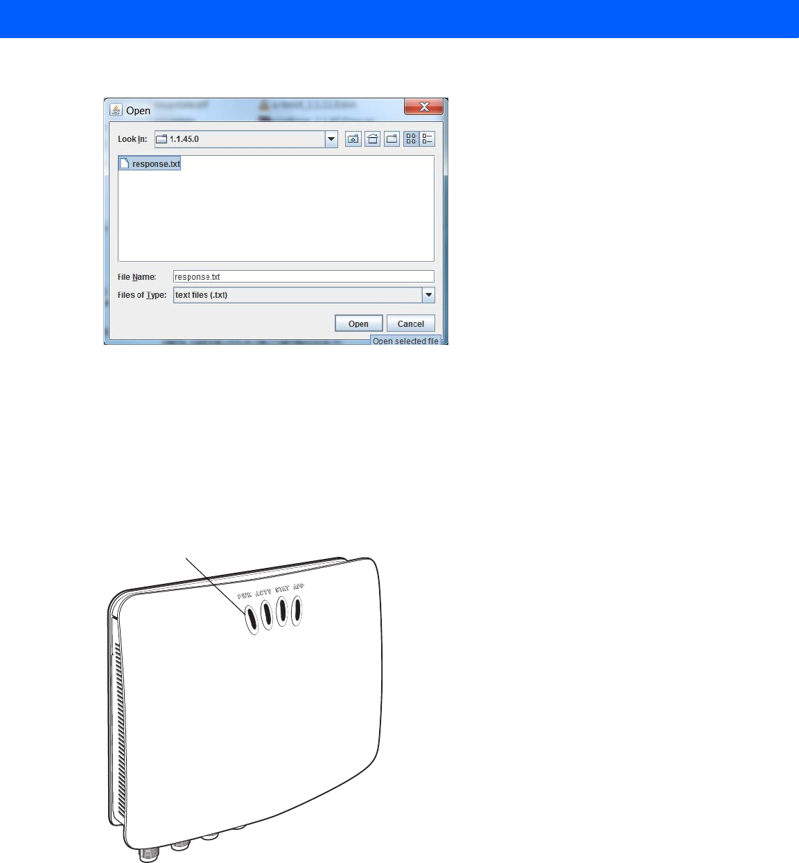
Firmware Upgrade 7 - 7
4. Click on Browse and navigate to the folder that contains the firmware update files.
Figure 7-8
Browsing Update Files
5. Select response.txt and click Open.
6. Click Start Update. The reader starts the update process and displays the update status as follows:
•The reader continuously blinks the Power LED red.
•The reader blinks all 4 LEDs orange once.
•The reader Power LED remains steady orange.
•The reader Power LED settles to a steady green to indicate that the update is complete.
Figure 7-9
Reader LEDs
When the update completes, the reader reboots and returns to the FX7500 login screen.
Power LED
Draft 2
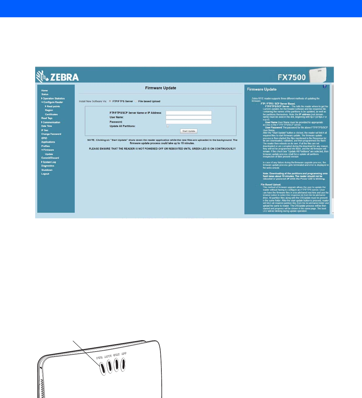
7 - 8 FX7500 RFID Reader Integrator Guide
FTP-Based Update
Copy all the update files into an appropriate FTP location.
1. Log into the reader and navigate to the Firmware Update page.
Figure 7-10
Firmware Update Window
2. Select FTP/FTPS Server.
3. Enter the FTP location where the files are located.
4. Enter the User Name and Password for the FTP server login.
5. Click Start Update. The reader starts the update process and displays the update status as follows:
•The reader continuously blinks the Power LED red.
•The reader blinks all 4 LEDs orange once.
•The reader Power LED remains steady orange.
•The reader Power LED settles to a steady green to indicate that the update is complete.
Figure 7-11
Reader LEDs
When the update completes, the reader reboots and returns to the FX7500 login screen.
Power LED
Draft 2
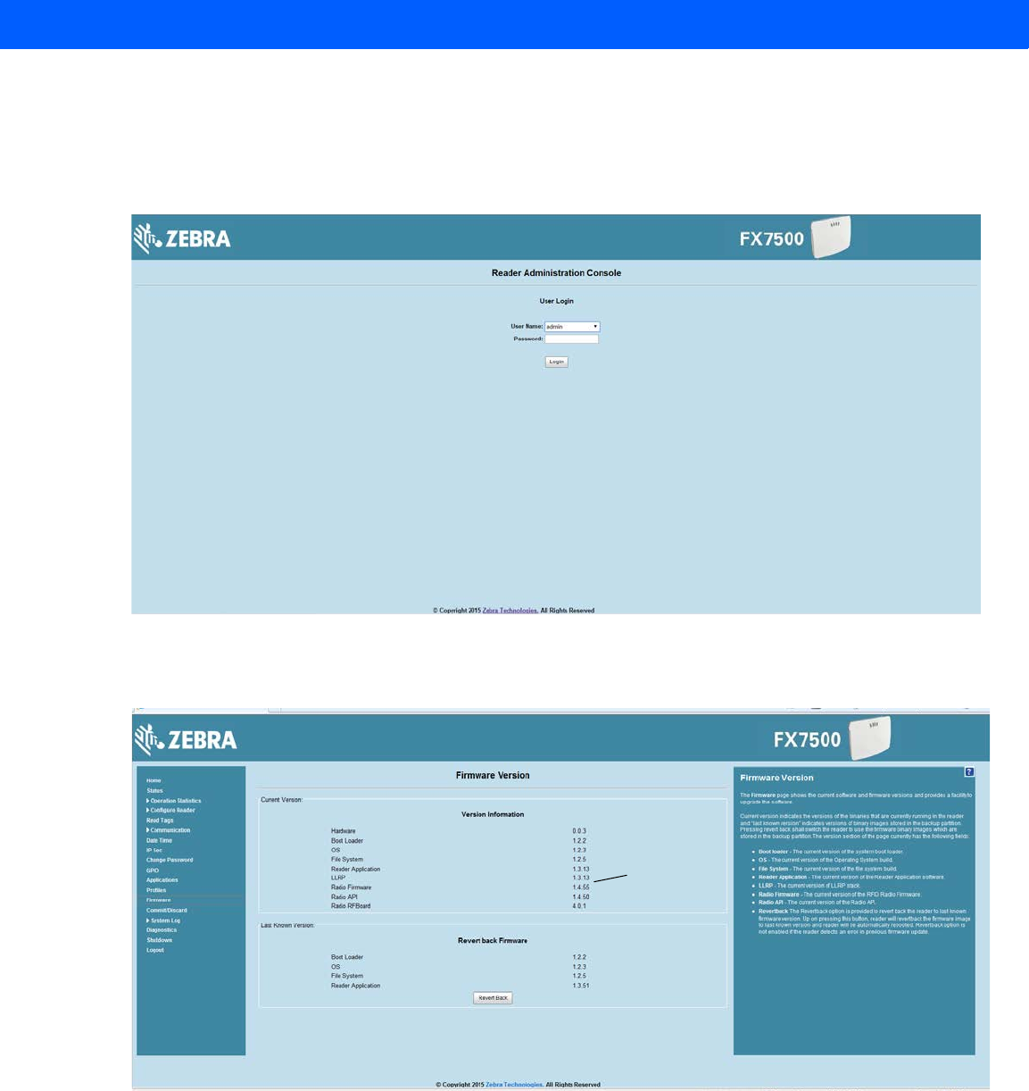
Firmware Upgrade 7 - 9
Verifying Firmware Version
To verify reader update success:
1. Log into the reader. In the User Login window, enter admin in the User Name: field and enter change in the
Password: field.
Figure 7-12
User Login Window
2. Select Firmware on the left side panel to verify that the current version of reader software is the new
version number, e.g., 1.1.68, which indicates that the update was successful.
Figure 7-13
Firmware Version Window
New Version
number
Draft 2

7 - 10 FX7500 RFID Reader Integrator Guide
Draft 2

CHAPTER 8 TROUBLESHOOTING
Table 8-1 provides FX7500 troubleshooting information.
Table 8-1
Troubleshooting
Problem/Error Possible Causes Possible Solutions
Reader error LED lights after the
reader is in operation. The CPU cannot
communicate. Refer to the system log for error messages.
Reader error LED stays lit on
power up. An error occurred during the
power up sequence. Refer to the system log for error messages.
Cannot access the
Administrator Console
.User name and password is
unknown. The default user name is
admin
and the
default password is
change
. To change the
user name and password, see
Communications Connections on page
3-5
.
Reader is not reading tags. The tag is out of its read
range. Move the tag into read range. See
Read
Tags on page 4-30
.
Antennas are not
connected. Connect antennas.
Tags are damaged. Confirm that tags are good.
Tags are not EPCgen2. Confirm that tags are EPCgen2.
If reading with the reader’s
web page, Java JRE 1.6 or
later is not installed.
Install Java JRE 1.6.
Cannot connect to the reader. The IP address is unknown. See
Communications Connections on
page 3-5
to view the IP address, or use the
host name to connect to the reader.
Draft 2

8 - 2 FX7500 RFID Reader Integrator Guide
Certain real time applications are
no longer functional. The node address, IP
address, or other reader
configuration parameter(s)
were changed using the
Administrator Console
, and
the application expects the
previous configuration.
Update the settings within the application.
Refer to the application manual.
The user closed the browser
without logging out of the
Administrator Console
, so
other applications cannot
connect to the reader.
Log out of the
Administrator Console
. The
applications can use the
Force Login
option
to log in even when the user closes the
browser without logging out.
Force Login
option is supported for the administrative
user.
Cannot log into
Administrator
Console
. The user forgot the
password. Press and hold the reset button for more
than 8 seconds. This resets the reader
configuration to factory defaults, including
the password. This also removes the
contents of the
apps
partition.
Unable to add SNTP server,
reader returning error:
Error: Cannot find the
specified Host Address
SNTP server is not
reachable. Ensure the SNTP server is accessible.
SNTP server name is not
resolvable via DNS server. Ensure the DNS server name is configured
in TCP/IP configuration.
DNS server is not
reachable. Ensure the DNS server is accessible.
Operation failed. A user operation did not
complete, typically due to
invalid input.
Validate all inputs and retry the operation. If
it is not successful, see
Service Information
on page xii
.
Invalid User Name and/or
Password - Try again. The user name and/or
password were not found in
the system, or do not match
the current user registry.
Accurately retype login information. If this is
not successful, see
Service Information on
page xii
.
Session has Timed-out - Log in
again. The current session was
inactive beyond the time-out
period (15 minutes), so the
system automatically logged
out.
Log in again. As a security precaution to
protect against unauthorized system
access, always log out of the system when
finished.
Table 8-1
Troubleshooting (Continued)
Problem/Error Possible Causes Possible Solutions
Draft 2

Troubleshooting 8 - 3
User name is not correct. The user name does not
match the current user
registry (illegal characters,
too long, too short,
unknown, or duplicate).
Accurately retype the user name.
User forgot the user ID.
Web console supports the
following users:
-
Admin
(default password
is
change
)
-
Guest
(no password
required)
-
rfidadm
- supported over
SSH,FTP/FTPS, SCP, but
not over
Administrator
Console
.
Reset the reader to factory defaults and
select
Admin
for user name and enter
change
in the password field to regain
access. See
Reset to Factory Defaults
LED Sequence on page 3-11
.
Not a legal IP address
(1.0.0.0 - 255.255.255.255).
Cannot reach the specified IP
address.
The SNMP Host Link is not valid.
The IP address entered is
either formatted inaccurately
or cannot be accessed
(pinged).
Accurately retype the IP address, and make
sure the host device is connected and
online. If this is not successful, see
Service
Information on page xii
.
Invalid network mask. The network mask entered
is not formatted correctly. Confirm the correct network mask from the
network administrator and enter it correctly.
Invalid SNMP version number. The version number for
SNMP protocol is not a
supported version.
Use version number 1 for SNMP version 1,
and 2 for SNMP version 2c.
Invalid description. The description contained
invalid characters (<,>,or'). Correct the description.
Invalid password. The password does not
match the current user
registry (illegal characters,
too long, or too short).
Accurately retype the password.
User forgot the password. Reset the reader to factory defaults and
select
Admin
for user name and enter
change
in the password field to regain
access. See
Reset to Factory Defaults
LED Sequence on page 3-11
.
The name, serial number, or IP
address entered already exists in
the system.
The name, serial number, or
IP address entered was
already used.
Enter a unique value for the new name,
serial number, or IP address.
Another administrator is currently
logged in. Try again later. The system does not allow
more than one administrator
to log in at a time.
Wait until the other administrator logs out
(or times out) before logging in or override
the current session with the new one.
Backup configuration file does
not exist. The system cannot revert to
a backup configuration
unless a backup file exists.
Commit the new configuration to create a
backup file.
Table 8-1
Troubleshooting (Continued)
Problem/Error Possible Causes Possible Solutions
Draft 2

8 - 4 FX7500 RFID Reader Integrator Guide
Failed to confirm the new
password. The system requires
entering the password
identically two times.
Accurately retype the password twice.
Network configuration change(s)
have not been saved. The user requested log out
prior to committing/
discarding the changes
made during the session.
Select one of the
Commit/Discard
options.
New password is the same as the
old one. The system requires
entering a new password
(different from the existing
password) during the
Change Password
operation.
Enter a password that is different from the
existing password.
Old password is not correct. The system requires
entering the existing
password during the
Change
Password
operation.
Accurately retype the existing password.
Unspecified error occurred -
code: #### A specific error message is
missing for the given status
code.
Note the code number, and contact Zebra
support. See
Service Information on page
xii
.
The requested page was not
found.
Internal Web Server Error.
The system experienced an
internal web server error. Contact Zebra support.
See
Service Information on page xii
Request method was NULL.
No query string was provided.
The system does not permit
executing a proxy program
from the command line
rather than the web server.
No action required. The system is reporting
that this action is not permitted.
Content length is unknown. The system cannot accept
an incorrectly formatted
HTTP POST request (from
an unsupported browser
application).
Use a GET request instead, or update the
software.
Couldn't read complete post
message. The system stopped a
POST operation before
completion.
Retry the operation, and allow it to
complete.
Unhandled reply type. The system generated an
unexpected value. Contact Zebra support.
See
Service Information on page xii
.
Failed to open port.
Failed to connect.
Failed to transmit.
Failed to receive.
Error during Receive of
Command.
Error during receive of
command. Contact Zebra support.
See
Service Information on page xii
.
Table 8-1
Troubleshooting (Continued)
Problem/Error Possible Causes Possible Solutions
Draft 2

Troubleshooting 8 - 5
Invalid Device Address. The device address
information (parent) is
invalid, missing, or
formatted inaccurately.
Contact Zebra support.
See
Service Information on page xii
.
Command parsing state error.
Missing argument for the
command.
Command internal type cast
error.
Missing operator.
Unknown operator.
A command was formatted
inaccurately. Contact Zebra support.
See
Service Information on page xii
.
The action must be confirmed. The user must confirm the
requested action before it is
executed.
Select the confirmation option when issuing
this request.
Invalid network adapter when
navigating to the Bluetooth
configuration page.
The Bluetooth dongle is not
plugged in or not supported. Plug in a supported Bluetooth dongle and
refresh the browser.
Wireless scan error. Wireless dongle is not
plugged in or not supported. Plug in a supported wireless dongle and
repeat the wireless scan.
Unable to connect to the wireless
network. Access point is off or
unreachable. Turn on the access point and make sure it is
accessible.
Encryption type is not
supported in the access
point.
Use one of the following supported
encryption types: WEP128, WPA/WPA2
and Open.
The wireless page displays
Adapter not found
.Connect the wireless adapter to the reader.
Wireless connection is complete,
but no IP address. No DHCP server is running
in the network. Add a DHCP server to the network.
OS update in progress. Firmware update on the
reader is ongoing. The
current operation is not
permitted.
Wait for the firmware update to complete
and then retry the operation.
Cannot change password. Cannot change password
for guest. Guest does not need a password to log in to
the Administrator Console.
Table 8-1
Troubleshooting (Continued)
Problem/Error Possible Causes Possible Solutions
NOTE If problems still occur, contact the distributor or call the local contact. See page xii for contact information.
Draft 2

8 - 6 FX7500 RFID Reader Integrator Guide
Draft 2

APPENDIX A TECHNICAL SPECIFICATIONS
FX7500 Kits
KT-FX75004US-01 4-Port US Reader Kit
•
FX7500-42310A30-US (4-port US reader)
•
AN480-CL66100WR (wide-band AN-480 antenna)
•
BRKT-70661-01R (antenna mounting bracket)
•
CBLRD-1B4001800R (15-foot RF cable)
•
50-14000-159R (power supply)
•
23844-00-00R (US power cord)
KT-FX75002US-01 2-Port US Reader Kit
•
FX7500-22310A30-US (2-port US reader)
•
AN480-CL66100WR (wide-band AN-480 antenna)
•
BRKT-70661-01R (antenna mounting bracket)
•
CBLRD-1B4001800R (15-foot RF cable)
•
50-14000-159R (power supply)
•
23844-00-00R (US power cord)
KT-FX75004WR-01 4-Port Global Reader Kit
•
FX7500-42315A30-US (4-port global reader)
•
AN480-CL66100WR (wide-band AN-480 antenna)
•
BRKT-70661-01R (antenna mounting bracket)
•
CBLRD-1B4001800R (15-foot RF cable)
•
50-14000-159R (power supply)
Draft 2

A - 2 FX7500 RFID Reader Integrator Guide
KT-FX75002WR-01 2-Port Global Reader Kit
•
FX7500-22315A30-US (2-port global reader)
•
AN480-CL66100WR (wide-band AN-480 antenna)
•
BRKT-70661-01R (antenna mounting bracket)
•
CBLRD-1B4001800R (15-foot RF cable)
•
50-14000-159R (power supply)
Technical Specifications
The following tables summarize the RFID reader intended operating environment and technical hardware
specifications.
Table A-1
Technical Specifications
Item FX
Physical and Environmental Characteristics
Dimensions 7.7 in. L x 5.9 in. W x 1.7 in. D
(19.56 cm L x 14.99 cm W x 4.32 cm D)
Weight 1.9 lbs ± 0.1 lbs (0.86 kg +/- 0.05 kg)
Base Material Die cast aluminum, sheet metal and plastic
Visual Status Indicators Multi-color LEDs: Power, Activity, Status, and Applications
Mounting Keyhole and standard VESA (75 mm x 75 mm)
FX Environmental Specifications
Operational Temperature -4° to +131° F / -20° to +55° C
Storage Temperature -40° to +158° F / -40° to +70° C
Humidity 5 to 95% non-condensing
Shock and Vibration MIL-STD-810G
Connectivity
Communications 10/100 BaseT Ethernet (RJ45) w/ POE support
USB Client (Type B), USB Host (Type A)
General Purpose I/O 2 inputs, 3 outputs, optically isolated (terminal block)
External 12V ~ 48 VDC power available for GPIO
Power POE or POE+
12 VDC to 48 VDC, or 24 VDC Universal Power Supply
Antenna Ports FX 7500-2: 2 mono-static ports (reverse polarity TNC)
FX 7500-4: 4 mono-static ports (reverse polarity TNC)
Draft 2

Technical Specifications A - 3
Hardware/OS and Firmware Management
Memory Flash 512 MB; DRAM 256 MB
Operating System Linux
Firmware Upgrade Web-based and remote firmware upgrade capabilities
Management Protocols RM 1.0.1 (with XML over HTTP/HTTPS and SNMP binding)
Network Services DHCP, HTTPS, FTPS, SFPT, SCP, SSH, HTTP, FTP, SNMP and NTP
Network Stack IPv4, IPv6
Security Transport Layer Security Ver. 1.2, FIPS 140-2 Level 1
Air Protocols EPCglobal UHF Class 1 Gen2, ISO 18000-6C
Frequency (UHF Band) Global Reader: 902 MHz to 928 MHz (Maximum, supports countries that use a part
of this band)
865 MHz to 868 MHz
US (only) Reader: 902 MHz to 928 MHz
Transmit Power Output 10dBm to +31.5dBm (POE+, 12V ~ 48V External DC,
Universal 24 VDC Power Supply;
+10dBm to +30.0dBm (POE)
Receive Sensitivity -82dBm
IP Addressing Static and Dynamic
Host Interface Protocol LLRP v1.0.1
API Support Host Applications – .NET, C and Java EMDK;
Embedded Applications – C & Java SDK
Warranty
The FX7500-4 and FX7500-2 are warranted against defects in workmanship and materials for a period of one
year (12 months) from date of shipment, provided the product remains unmodified and is operated under normal
and proper conditions.
For the complete Zebra hardware product warranty statement, go to:
http://www.zebra.com/warranty
Recommended Services
Support Services Service from the Start Advance Exchange On-Site System Support Support
Advanced Services RFID Design and Deployment Services
Table A-1
Technical Specifications (Continued)
Item FX
Draft 2
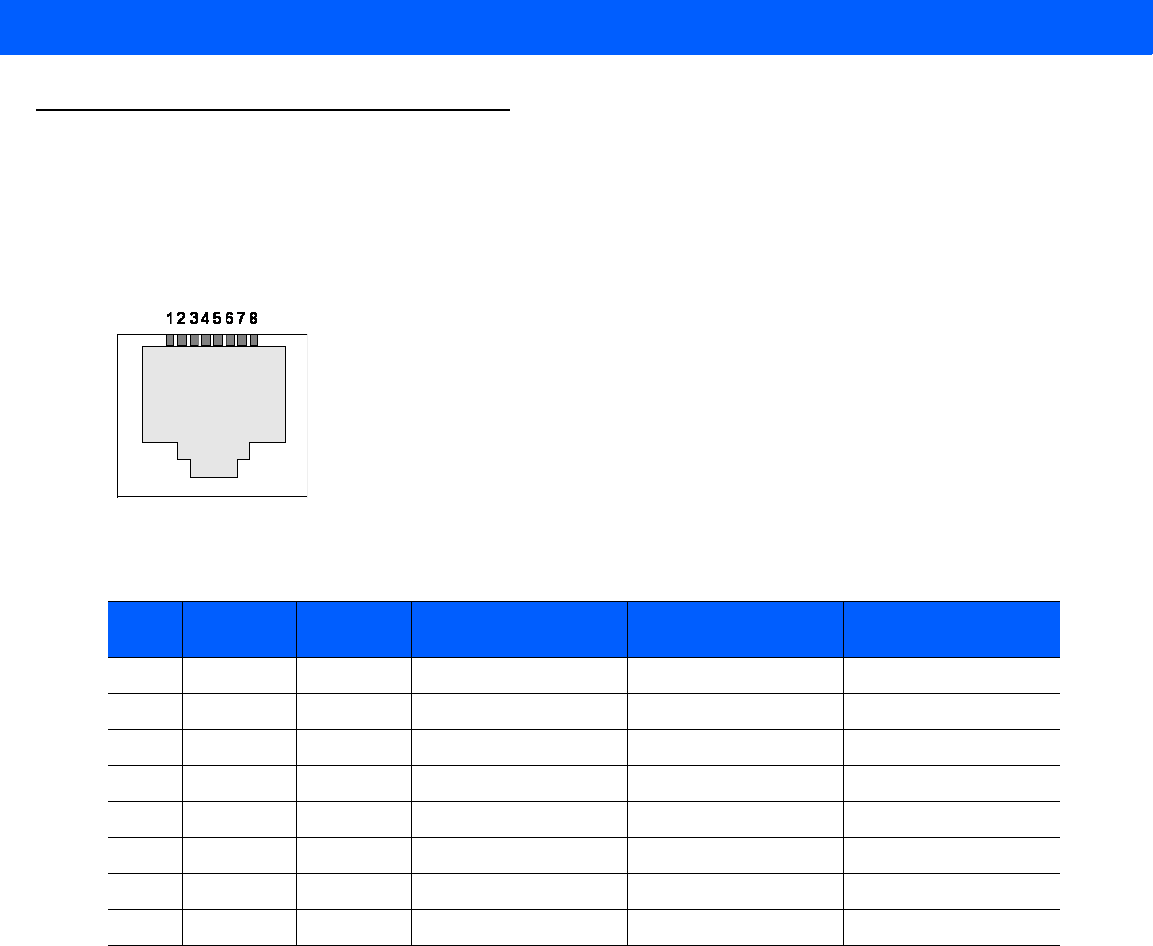
A - 4 FX7500 RFID Reader Integrator Guide
Cable Pinouts
10/100bT Ethernet / POE Connector
The 10/100BT Ethernet / POE connector is an RJ45 receptacle. This port complies with the IEE 802.3af
specification for Powered Devices.
Figure A-1
Ethernet Connections
Table A-2
10/100bT Ethernet / POE Connector Pinout
Pin Pin Name Direction Description POE Mode A
Function
POE Mode B
Function
Pin 1 TX-P O TX Data Positive Positive Vport
Pin 2 TX-N O TX Data Negative Positive Vport
Pin 3 RX-P I RX Data Positive Negative Vport
Pin 4 NC - No Connect Positive Vport
Pin 5 NC - No Connect Positive Vport
Pin 6 RX_N I RX Data Negative Negative Vport
Pin 7 NC - No Connect Negative Vport
Pin 8 NC - No Connect Negative Vport
Draft 2
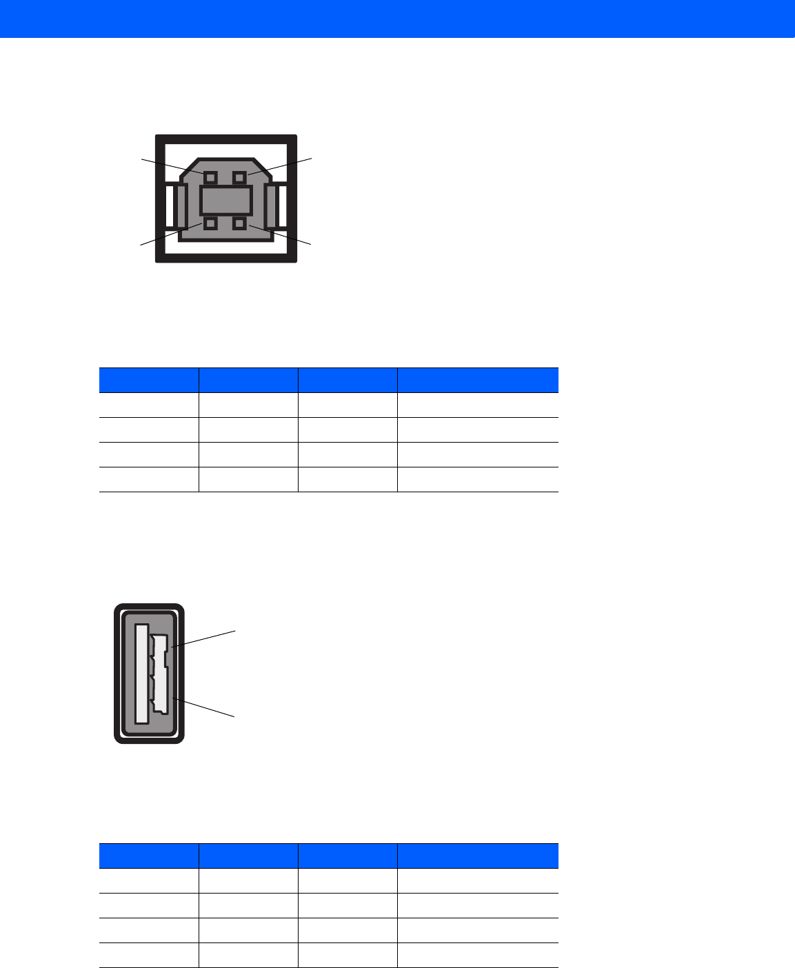
Technical Specifications A - 5
USB Client Connector
The USB Client port is supplied on a USB Type B connector.
Figure A-2
USB Client Connector
USB Host Connector
The USB Host port is supplied on a USB Type A flag connector.
Figure A-3
USB Host Connector (J22)
Table A-3
USB Client Port Connector Pinout
Pin Pin Name Direction Description
Pin 1 5.0V_USB I 5.0V USB Power Rail
Pin 2 USB_DN I/O Data Negative
Pin 3 USB_DP I/O Data Positive
Pin 4 GND - Ground
Pin 4Pin 3
Pin 1Pin 2
Table A-4
USB Host Port Connector (J22) Pinout
Pin Pin Name Direction Description
Pin 1 V_USB I 5.0V USB Power Rail
Pin 2 USBH_DN I/O Data Negative Rail
Pin 3 USBH_DP I/O Data Positive Rail
Pin 4 GND - Ground
Pin 1
Pin 4
Draft 2
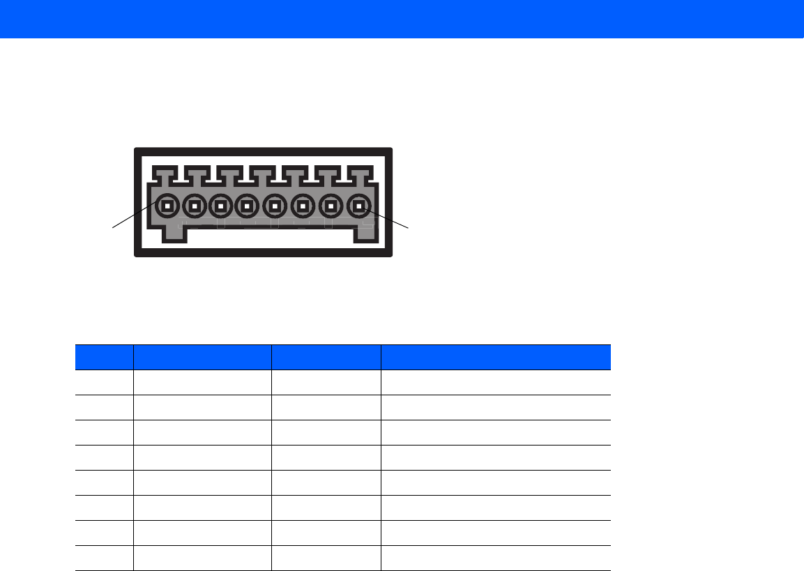
A - 6 FX7500 RFID Reader Integrator Guide
GPIO Port Connections
These plug terminal block types allow connecting and disconnecting individual wires independently. A single
connector is used for both inputs and outputs. See Table A-5 for pin descriptions.
Figure A-4
FX7500 RFID Reader GPIO Connection
Table A-5
GPIO Pin Outs
Pin # Pin Name Direction Description
1 +24V DC Power O Supplies +24V DC at up to 1 Amp
2 GP output #1 O Signal for GP output #1
3 GP output #2 O Signal for GP output #2
4 GP output #3 O Signal for GP output #3
5 GND - Ground connection
6 GP input #1 I Signal for GP input #1
7 GP input #2 I Signal for GP input #2
8 GND - Ground connection
Pin 8Pin 1
Draft 2

APPENDIX B STATIC IP CONFIGURATION
Introduction
This appendix describes three methods of setting the static IP address on an FX7500 RFID Reader.
Reader IP Address or Host Name is Known - Set the Static IP Using the Web
Console
1. Browse the device using the host name, e.g., FX7500CD3B1E.
2. Log onto the device.
Figure B-1
Reader Administration Console Login Window
3. Click Communication.
Draft 2
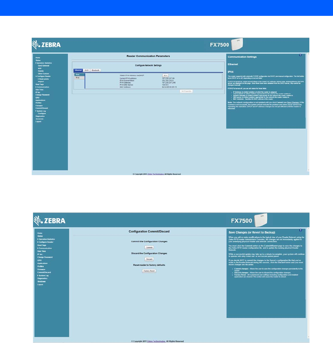
B - 2 FX7500 RFID Reader Integrator Guide
4. Set Obtain IP Address via DHCP to Off and enter all required information.
Figure B-2
Reader Communication Parameters Window
5. Click Set Properties. You can set a static IP that doesn't belong to this DHCP network.
6. Click Commit/Discard, then click the Commit button.
Figure B-3
Commit/Discard Window
7. The message Reader IP Address config has changed. Needs reader reboot to take effect appears. Reset the
device and use the reader with the static IP network.
Draft 2
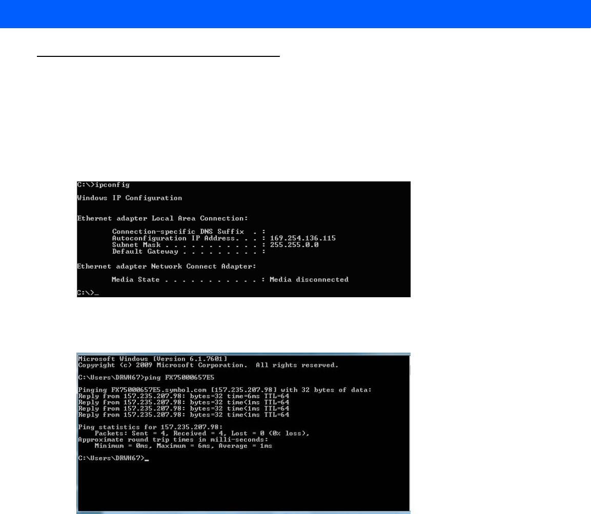
Static IP Configuration B - 3
Reader IP is Not Known (DHCP Network Not Available) - Set the Static IP Using
the Web Console
1. Connect the device and a PC running Windows XP to the same network that doesn't have a DHCP server,
or connect the device directly to the PC.
2. Ensure both the device and PC Ethernet jack use at least one LED to indicate network connection detect.
3. If the PC uses an assigned static IP, update it to use DHCP. The PC obtains an IP that starts with 169.
Figure B-4
Obtain IP Address
4. When possible, ping the host name of the device.
Figure B-5
Ping the Host Name
5. Use a browser to connect to the device with the host name, e.g., FX7500CD3B1E, or use the IP address
obtained from ping replies (e.g. 169.254.62.74).
6. Log onto the device.
7. Click Communication.
Draft 2
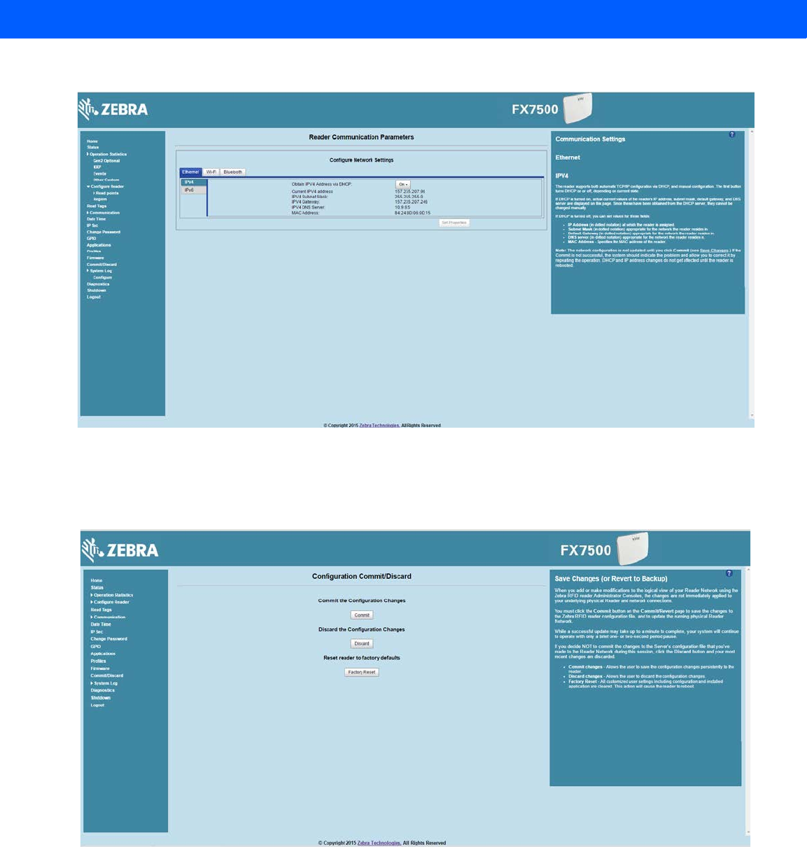
B - 4 FX7500 RFID Reader Integrator Guide
8. Set Obtain IP Address via DHCP to Off and enter all required information.
Figure B-6
Reader Communication Parameters Window
9. Click Set Properties.
10. Click Commit/Discard, then click the Commit button.
Figure B-7
Commit/Discard Window
11. The message Reader IP Address config has changed. Needs reader reboot to take effect appears. Reset the
device and use the reader with the static IP network.
Draft 2

APPENDIX C RF AIR LINK CONFIGURATION
Introduction
This appendix lists the different air link configurations supported. The air link configuration is available through
LLRP and RFID3 API interfaces.
Radio Modes
The supported modes are exposed as a list of individual UHFC1G2RfModeTableEntry parameters in regulatory
capabilities as shown in Table C-1 and Table C-2. The Mode Index column refers to the index used to walk the
C1G2UHFRFModeTable. Refer to the EPCglobal Low Level Reader Protocol (LLRP) Standard.
Table C-1
Radio Modes for FCC Readers
RF Mode
Index
Divide
Ratio
BDR
Value
M Value
M2=2,
FM0=1,
M4=4,
M8=8
FLM
Value
PIE
Value
Min
Tari
Max
Tari
Step
Tari
Spectral
Mask
Indica-
tor**
EPC HAG
T&C
Conform-
ance
1 64/3 640000 1 PR_ASK 1500 6250 6250 0 Dense false
2 64/3 640000 1 PR_ASK 2000 6250 6250 0 Dense false
3 64/3 120000 2 PR_ASK 1500 25000 25000 0 Dense false
4 64/3 120000 2 PR_ASK 1500 12500 23000 2100 Dense false
5 64/3 120000 2 PR_ASK 2000 25000 25000 0 Dense false
6 64/3 120000 2 PR_ASK 2000 12500 23000 2100 Dense false
7 64/3 128000 2 PR_ASK 1500 25000 25000 0 Dense false
8 64/3 128000 2 PR_ASK 1500 12500 23000 2100 Dense false
9 64/3 128000 2 PR_ASK 2000 25000 25000 0 Dense false
*RF Mode 23 is the automac air link profile which is also the default.
**Spectral mask indicator may vary for certain Tari values. Detailed information is available upon
request.
Draft 2

C - 2 FX7500 RFID Reader Integrator Guide
10 64/3 128000 2 PR_ASK 2000 12500 23000 2100 Dense false
11 64/3 160000 2 PR_ASK 1500 12500 18800 2100 Dense false
12 64/3 160000 2 PR_ASK 2000 12500 18800 2100 Dense false
13 64/3 60000 4 PR_ASK 1500 25000 25000 0 Dense false
14 64/3 60000 4 PR_ASK 1500 12500 23000 2100 Dense false
15 64/3 60000 4 PR_ASK 2000 25000 25000 0 Dense false
16 64/3 60000 4 PR_ASK 2000 12500 23000 2100 Dense false
17 64/3 64000 4 PR_ASK 1500 25000 25000 0 Dense false
18 64/3 64000 4 PR_ASK 1500 12500 23000 2100 Dense false
19 64/3 64000 4 PR_ASK 2000 25000 25000 0 Dense false
20 64/3 64000 4 PR_ASK 2000 12500 23000 2100 Dense false
21 64/3 80000 4 PR_ASK 1500 12500 18800 2100 Dense false
22 64/3 80000 4 PR_ASK 2000 12500 18800 2100 Dense false
*23 64/3 variable variable PR_ASK variable 6250 25000 variable variable false
24 64/3 320000 1 PR_ASK 1500 12500 18800 2100 Dense false
25 64/3 320000 1 PR_ASK 2000 12500 18800 2100 Dense false
26 64/3 30000 8 PR_ASK 1500 25000 25000 0 Dense false
27 64/3 30000 8 PR_ASK 1500 12500 23000 2100 Dense false
28 64/3 30000 8 PR_ASK 2000 25000 25000 0 Dense false
29 64/3 30000 8 PR_ASK 2000 12500 23000 2100 Dense false
30 64/3 32000 8 PR_ASK 1500 25000 25000 0 Dense false
31 64/3 32000 8 PR_ASK 1500 12500 23000 2100 Dense false
32 64/3 32000 8 PR_ASK 2000 25000 25000 0 Dense false
33 64/3 32000 8 PR_ASK 2000 12500 23000 2100 Dense false
34 64/3 40000 8 PR_ASK 1500 12500 18800 2100 Dense false
35 64/3 40000 8 PR_ASK 2000 12500 18800 2100 Dense false
Table C-1
Radio Modes for FCC Readers (Continued)
RF Mode
Index
Divide
Ratio
BDR
Value
M Value
M2=2,
FM0=1,
M4=4,
M8=8
FLM
Value
PIE
Value
Min
Tari
Max
Tari
Step
Tari
Spectral
Mask
Indica-
tor**
EPC HAG
T&C
Conform-
ance
*RF Mode 23 is the automac air link profile which is also the default.
**Spectral mask indicator may vary for certain Tari values. Detailed information is available upon
request.
Draft 2

RF Air Link Configuration C - 3
Table C-2
Radio Modes for ETSI Readers
RF Mode
Index
Divide
Ratio
BDR
Value
M Value
M2=2,
FM0=1,
M4=4,
M8=8
FLM
Value
PIE
Value
Min
Tari
Max
Tari
Step
Tari
Spectral
Mask
Indica-
tor**
EPC HAG
T&C
Conform-
ance
1 64/3 120000 2 PR_ASK 1500 25000 25000 0 Dense false
2 64/3 120000 2 PR_ASK 1500 12500 23000 2100 Dense false
3 64/3 120000 2 PR_ASK 2000 25000 25000 0 Dense false
4 64/3 120000 2 PR_ASK 2000 12500 23000 2100 Dense false
5 64/3 128000 2 PR_ASK 1500 25000 25000 0 Dense false
6 64/3 128000 2 PR_ASK 1500 12500 23000 2100 Dense false
7 64/3 128000 2 PR_ASK 2000 25000 25000 0 Dense false
8 64/3 128000 2 PR_ASK 2000 12500 23000 2100 Dense false
9 64/3 160000 2 PR_ASK 1500 12500 18800 2100 Dense false
10 64/3 160000 2 PR_ASK 2000 12500 18800 2100 Dense false
11 64/3 60000 4 PR_ASK 1500 25000 25000 0 Dense false
12 64/3 60000 4 PR_ASK 1500 12500 23000 2100 Dense false
13 64/3 60000 4 PR_ASK 2000 25000 25000 0 Dense false
14 64/3 60000 4 PR_ASK 2000 12500 23000 2100 Dense false
15 64/3 64000 4 PR_ASK 1500 25000 25000 0 Dense false
16 64/3 64000 4 PR_ASK 1500 12500 23000 2100 Dense false
17 64/3 64000 4 PR_ASK 2000 25000 25000 0 Dense false
18 64/3 64000 4 PR_ASK 2000 12500 23000 2100 Dense false
19 64/3 80000 4 PR_ASK 1500 12500 18800 2100 Dense false
20 64/3 80000 4 PR_ASK 2000 12500 18800 2100 Dense false
*21 64/3 variable variable PR_ASK variable 12500 25000 variable variable false
22 64/3 320000 1 PR_ASK 1500 12500 18800 2100 Dense false
23 64/3 320000 1 PR_ASK 2000 12500 18800 2100 Dense false
24 64/3 30000 8 PR_ASK 1500 25000 25000 0 Dense false
25 64/3 30000 8 PR_ASK 1500 12500 23000 2100 Dense false
26 64/3 30000 8 PR_ASK 2000 25000 25000 0 Dense false
*RF Mode 21 is the automac air link profile which is also the default.
**Spectral mask indicator may vary for certain Tari values. Detailed information is available upon
request.
Draft 2

C - 4 FX7500 RFID Reader Integrator Guide
27 64/3 30000 8 PR_ASK 2000 12500 23000 2100 Dense false
28 64/3 32000 8 PR_ASK 1500 25000 25000 0 Dense false
29 64/3 32000 8 PR_ASK 1500 12500 23000 2100 Dense false
30 64/3 32000 8 PR_ASK 2000 25000 25000 0 Dense false
31 64/3 32000 8 PR_ASK 2000 12500 23000 2100 Dense false
32 64/3 40000 8 PR_ASK 1500 12500 18800 2100 Dense false
33 64/3 40000 8 PR_ASK 2000 12500 18800 2100 Dense false
Table C-2
Radio Modes for ETSI Readers (Continued)
RF Mode
Index
Divide
Ratio
BDR
Value
M Value
M2=2,
FM0=1,
M4=4,
M8=8
FLM
Value
PIE
Value
Min
Tari
Max
Tari
Step
Tari
Spectral
Mask
Indica-
tor**
EPC HAG
T&C
Conform-
ance
*RF Mode 21 is the automac air link profile which is also the default.
**Spectral mask indicator may vary for certain Tari values. Detailed information is available upon
request.
Draft 2

APPENDIX D CONNECTING WI-FI AND
BLUETOOTH DONGLES
Introduction
This appendix describes how to connect to a wireless network using a USB Wi-Fi dongle on the FX7500, and
how to connect to a peer device over Bluetooth using a USB Bluetooth dongle.
Connecting to a Wireless Network Using a Wi-Fi Dongle
To connect to a wireless network using a USB Wi-Fi dongle on the FX7500:
1. Plug the supported wireless dongle into the USB host port on the FX7500. Supported dongles are:
•
Wi-Fi over USB adapters with Realtek chipset RTL 8187
•
The following devices were tested:
•Alfa AWUS036H, visit http://www.alfa.com.tw/in/front/bin/ptlist.phtml?Category=10541
•CCrane Versa Wifi USB Adapter II, visit
http://www.ccrane.com/antennas/wifi-antennas/versa-wifi-usb-adapter-II.aspx
Figure D-1
USB Host Port Location for Dongle
Port 1 Port 2 Port 3 Port 4 GPIO 24 VDC
USB Host Port
Draft 2
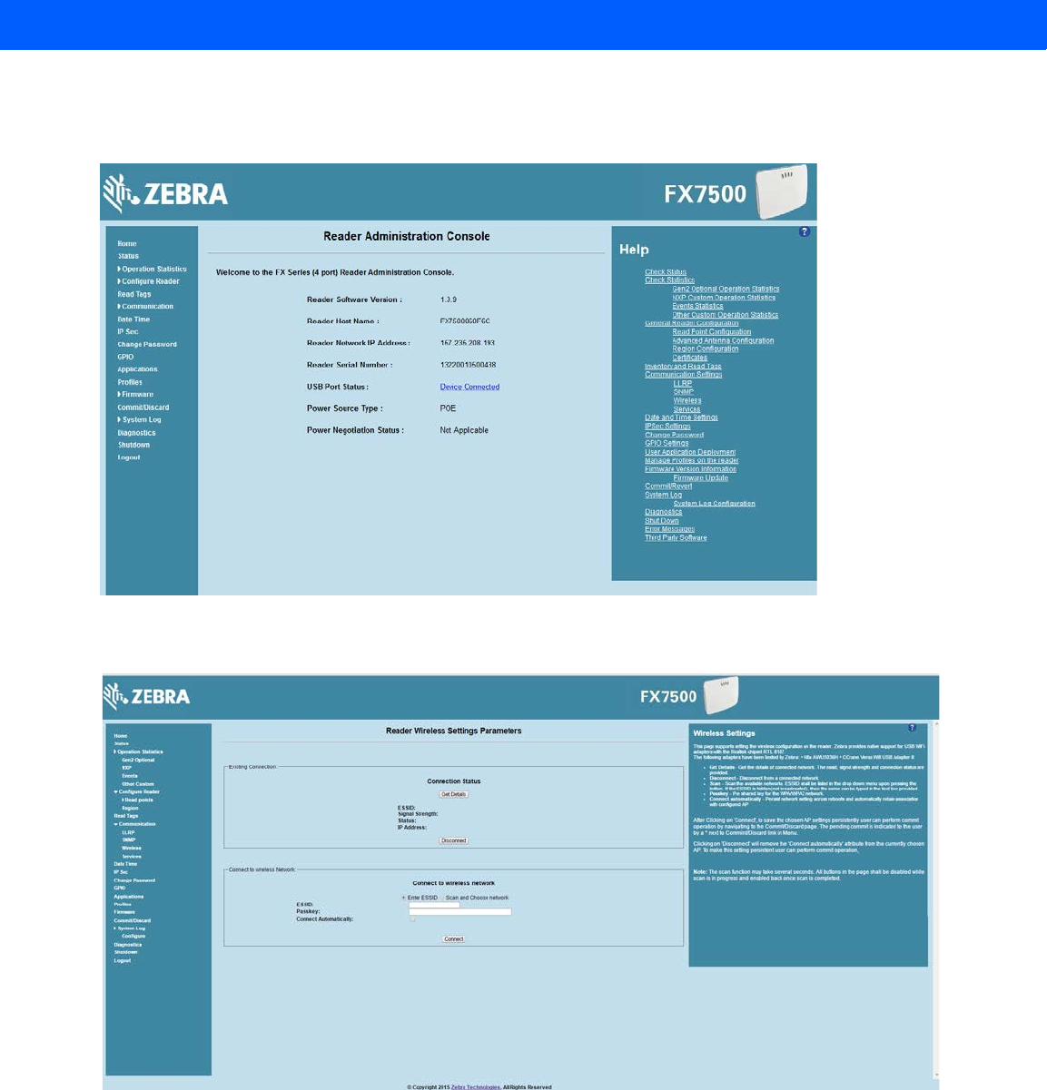
D - 2 FX7500 RFID Reader Integrator Guide
2. To confirm that the Wi-Fi dongle is detected properly, log in to the reader Administrator Console. On the
Home page ensure the USB Port Status displays Device Connected. Hover the mouse pointer over this link
to display the WiFi dongle information shown in Figure D-2.
Figure D-2
Wi-Fi Dongle Connected
3. Select Communication > Wireless.
Figure D-3
Wireless Settings
The WiFi dongle can connect to the wireless network in one of two ways:
•Manually entering the ESSID (if known).
•Scanning the current list of APs and choosing the correct one to connect to.
Draft 2
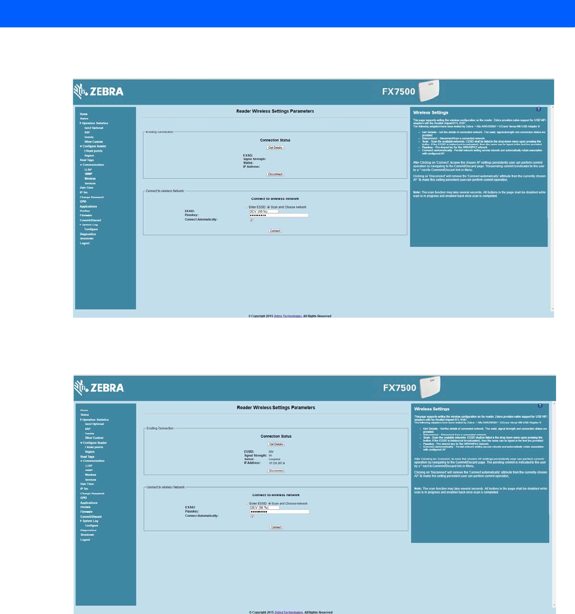
Connecting Wi-Fi and Bluetooth Dongles D - 3
4. Once the APs are scanned, enter the appropriate passkey and enable Connect Automatically (if required to
connect to the AP automatically if the connection is lost).
Figure D-4
Entering Connect Information
5. Select Connect. When the connection to the AP succeeds, an IP is assigned and appears in the
IP Address field.
Figure D-5
Assigned IP Address
The reader is now accessible using the wireless IP shown in the IP Address field (157.235.207.24 in this case).
The WiFi interface supports dynamic addressing mechanisms for both IPV4 and IPv6. There is no provision to
set a static IP address.
For wireless IP address details, select Communication > Wi-Fi tab.
Draft 2
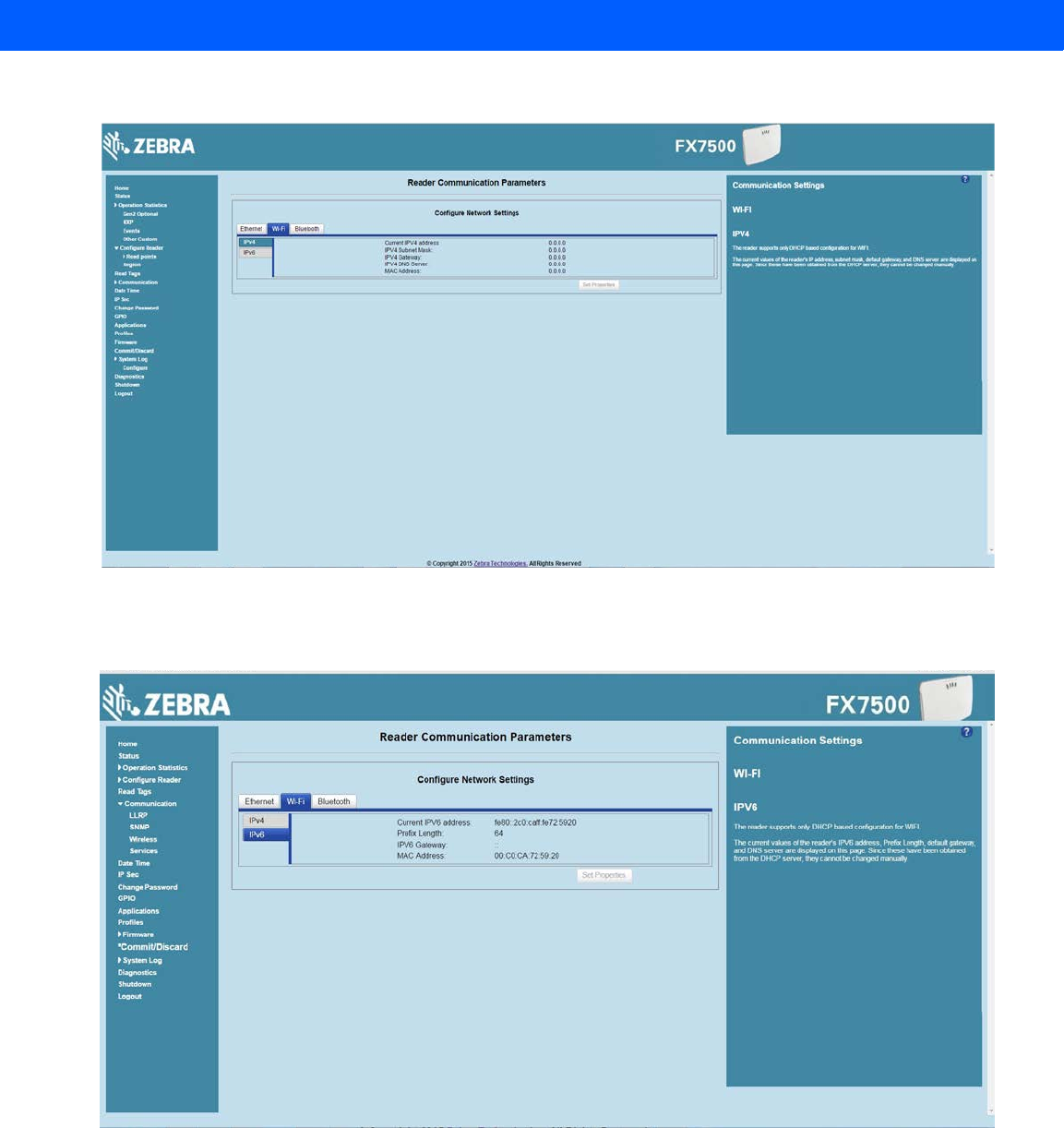
D - 4 FX7500 RFID Reader Integrator Guide
Figure D-6
Wi-Fi Tab - IPV4
The reader can also be accessed via Wi-Fi using an IPV6 address if supported by the network to which the API
is connected.
Figure D-7
Wi-Fi Tab - IPV6
Draft 2
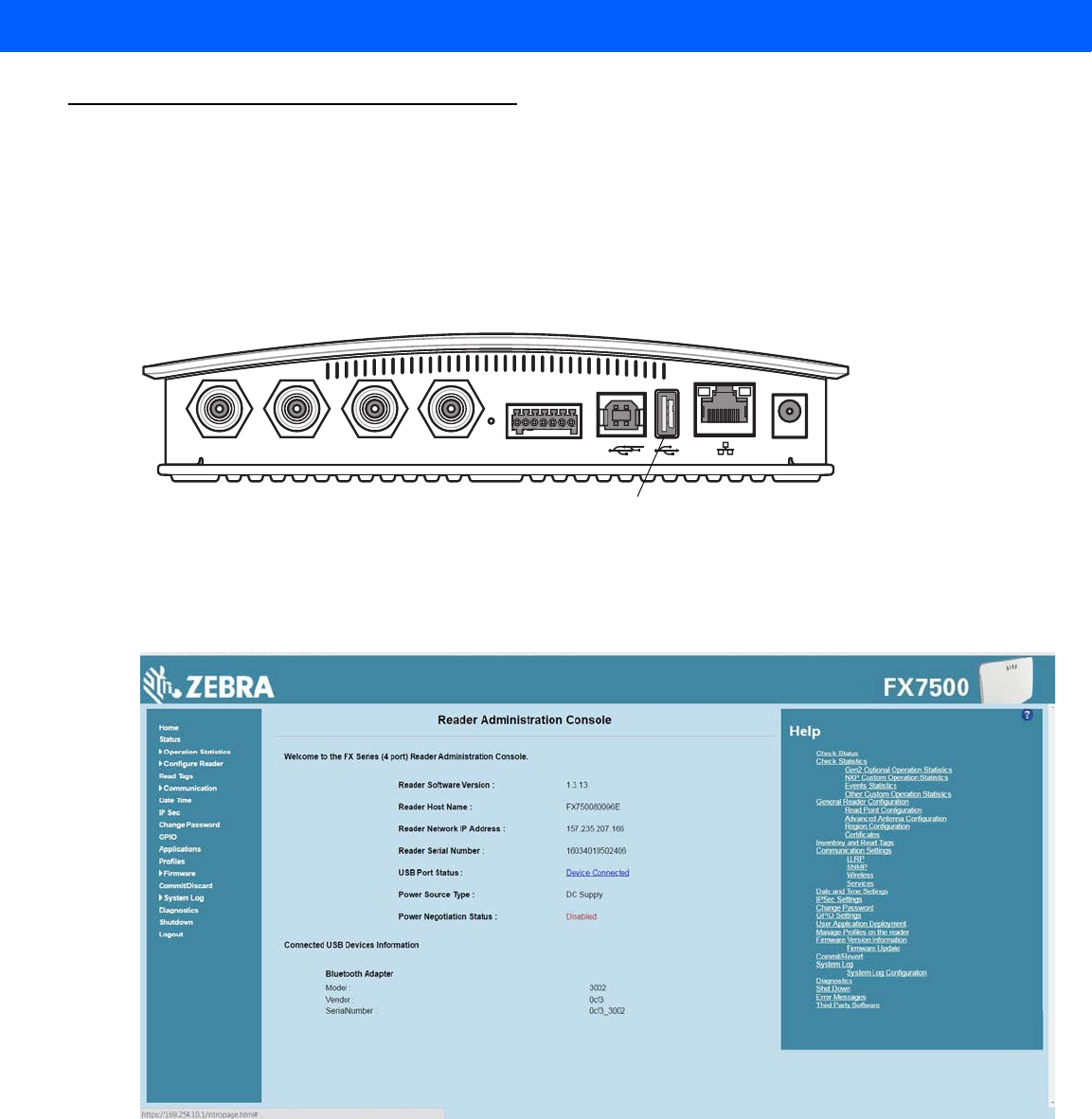
Connecting Wi-Fi and Bluetooth Dongles D - 5
Connecting to a Peer Device over Bluetooth Using a Bluetooth Dongle
To connect to a peer device over Bluetooth using a USB Bluetooth dongle on the FX7500:
1. Plug the supported Bluetooth dongle into the USB host port on the FX7500. The following Bluetooth
dongles are supported on the FX7500:
•Asus Mini Bluetooth Dongle USB-BT211.
•MediaLink Bluetooth Dongle MUA-BA3.
Figure D-8
USB Host Port Location for Dongle
2. To confirm that the Bluetooth dongle is detected properly, log in to the reader Administrator Console. On
the Home page ensure the USB Port Status displays Device Connected. Hover the mouse pointer over this
link to display the Bluetooth dongle information.
Figure D-9
Bluetooth Dongle Connected
3. Select Communication > Bluetooth.
Port 1 Port 2 Port 3 Port 4 GPIO 24 VDC
USB Host Port
Draft 2
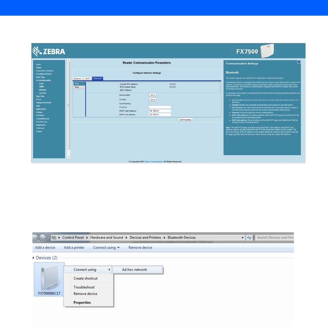
D - 6 FX7500 RFID Reader Integrator Guide
4. Change the Discoverable and Pairable properties to On.
Figure D-10
Changing Discoverable and Pairable Properties
5. Optionally select Use Passkey and enter a passkey to validate the Bluetooth connection. The default
passkey for the FX7500 is 0000.
6. Discover the reader from a Bluetooth-enabled device (such as a laptop). Use the host name to identify the
reader among the discovered devices (e.g., FX7500060C17).
7. After a successful connection, right-click the reader icon (e.g., FX7500060C17) in the list of Bluetooth
devices and select Connect using > Ad hoc network. This establishes the network connection for later.
Figure D-11
Connecting to the Reader
8. The IP address assigned to the Bluetooth interface is 192.168.XX.XX. The last 2 octets are the last 2
octets of the Bluetooth MAC address (found in the Properties window on the PC once the Bluetooth
Draft 2
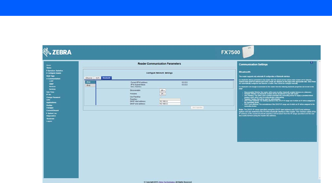
Connecting Wi-Fi and Bluetooth Dongles D - 7
connection is established). Also find this in the Communication > Bluetooth page. Both IPV4 and IPV6
based IP address are supported for adhoc Bluetooth connection between the reader and the client.
Figure D-12
Communication Bluetooth Tab
9. Open the web page or sample application to connect to the Bluetooth IP (192.168.67.21 in Figure D-12)
and read tags.
Draft 2

D - 8 FX7500 RFID Reader Integrator Guide
Draft 2

APPENDIX E COPYING FILES TO AND
FROM THE READER
Introduction
The FX7500 reader supports the SCP, FTP, and FTPS protocols for copying files.
SCP
The following examples illustrate SCP use:
scp SourceFileName rfidadm@MyReaderIP:/apps
scp rfidadm@MyReaderIP:/apps/SourceFileName userid@MyLinuxMachineIP:/MyFolderName
FTP
The following examples illustrate FTP use:
ftp> open
To 157.235.207.146
Connected to 157.235.207.146.
220 Welcome to Thredbo FTP service.
User (157.235.207.146:(none)): rfidadm
331 Please specify the password.
Password:
230 Login successful.
ftp>
Use FTP commands such as is, get, and put to manage files. For more information on FTP commands refer to
http://www.cs.colostate.edu/helpdocs/ftp.html. GUI applications such as FileZilla are also supported on
Windows and Linux machines to connect to the FX7500.
Draft 2

E - 2 FX7500 RFID Reader Integrator Guide
FTPS
Use any standard GUI tool such as FileZilla to connect to the FX7500 reader over FTPS.
Draft 2

APPENDIX F DATA PROTECTION
Introduction
The FX7500 stores data in transition when it detects a network condition that prevents the reader from sending
data. This applies to RFID tag data that the reader application is transmitting to the outbound TCP socket, and
is no longer owned by the RFID application because it was sent to the network layer for transmission.
When the reader cannot queue RFID data in the outbound TCP socket when an LLRP connection is already
established, it stores all outbound LLRP messages in the data protection queue. The queue can store up to
66,000 messages, which represents more than 5 minutes worth of data when reading 200 tags/second (the
nominal data rate in DRM (dense reader mode) configuration). If the network is still unavailable when the data
protection queue is full, the oldest messages are discarded to accommodate the most recent tag reports.
This feature can not be disabled and operates regardless of the physical network interface used, meaning
RFID data over WiFi and Bluetooth is also protected.
Draft 2

F - 2 FX7500 RFID Reader Integrator Guide
Draft 2

INDEX
Numerics
10/100BaseT Ethernet . . . . . . . . . . . . . . . . 1-2, 2-4, 2-5
2-port reader . . . . . . . . . . . . . . . . . . . . . . . . . . . . . . . 2-4
4-port reader . . . . . . . . . . . . . . . . . . . . . . . . . . . . . . . 2-4
A
administrator console . . . . . . . . . . . . . . . . . . . . . . . . 4-1
applications . . . . . . . . . . . . . . . . . . . . . . . . . . . . 4-42
committing changes . . . . . . . . . . . . . . . . . . . . . 4-45
communication settings . . . . . . . . . . . . . . . . . . 4-31
configure network services . . . . . . . . . . . . . . . . 4-37
configure network settings . . . . . . . 4-31, 4-32, 4-33
configuring system log . . . . . . . . . . . . . . . . . . . 4-47
discarding changes . . . . . . . . . . . . . . . . . . . . . . 4-45
firmware version . . . . . . . . . . . . . . . . . . . . 4-44, 4-45
GPIO . . . . . . . . . . . . . . . . . . . . . . . . . . . . . . . . . 4-41
IPV6 sec . . . . . . . . . . . . . . . . . . . . . . . . . . . . . . 4-39
login . . . . . . . . . . . . . . . . . . . . . . . . . . . . . . . . . . 4-6
main screen . . . . . . . . . . . . . . . . . . . . . . . . . . . . 4-9
managing login . . . . . . . . . . . . . . . . . . . . . . . . . 4-41
reader diagnostics . . . . . . . . . . . . . . . . . . . . . . 4-48
reader profiles . . . . . . . . . . . . . . . . . . . . . . . . . . 4-43
scan control . . . . . . . . . . . . . . . . . . . . . . . . 1-6, 4-30
set password . . . . . . . . . . . . . . . . . . . . . . . . . . 4-40
setting date and time . . . . . . . . . . . . . . . . . . . . 4-38
shutting down . . . . . . . . . . . . . . . . . . . . . . . . . . 4-49
status . . . . . . . . . . . . . . . . . . . . . . . . . . . . . . . . 4-10
system log . . . . . . . . . . . . . . . . . . . . . . . . . . . . 4-46
air link . . . . . . . . . . . . . . . . . . . . . . . . . . . . . . . . . . . . C-1
antennas . . . . . . . . . . . . . . . . . . . . . . . . . . . . . . . . . . 2-2
configuring . . . . . . . . . . . . . . . . . . . . . . . . . . . . 4-18
installing . . . . . . . . . . . . . . . . . . . . . . . . . . . . . . . 3-4
ports . . . . . . . . . . . . . . . . . . . . . . . . . . . 1-2, 2-4, 2-5
applications . . . . . . . . . . . . . . . . . . . . . . . . . . . . . . . 4-42
B
backup . . . . . . . . . . . . . . . . . . . . . . . . . . . . . . . . . . . . 2-7
bluetooth . . . . . . . . . . . . . . . . . . . . . . . . . . . . . . . . . .D-5
connecting . . . . . . . . . . . . . . . . . . . . . . . . . . . . . .D-5
C
cable pinouts . . . . . . . . . . . . . . . . . . . . . . . . . . . . . . . A-4
ethernet . . . . . . . . . . . . . . . . . . . . . . . . . . . . . . . . A-4
GPIO . . . . . . . . . . . . . . . . . . . . . . . . . . . . . . . . . . A-6
USB . . . . . . . . . . . . . . . . . . . . . . . . . . . . . . . . . . . A-5
USB client . . . . . . . . . . . . . . . . . . . . . . . . . . . . . . A-5
USB host . . . . . . . . . . . . . . . . . . . . . . . . . . . . . . . A-5
chapter descriptions . . . . . . . . . . . . . . . . . . . . . . . . . . . .x
client applications . . . . . . . . . . . . . . . . . . . . . . . . . . . . 2-7
commit region change . . . . . . . . . . . . . . . . . . . . . . . . 1-5
committing changes . . . . . . . . . . . . . . . . . . . . . . . . . 4-45
communication . . . . . . . . . . . . . . . . . . . . . . . . . . . . . . 2-5
ethernet, wired . . . . . . . . . . . . . . . . . . . . . . . . . . . 3-5
communication settings . . . . . . . . . . . . . . . . . . . . . . 4-31
configurations . . . . . . . . . . . . . . . . . . . . . . . . . . . . . . . ix
configure
administrator console . . . . . . . . . . . . . . . . . . . . . 2-7
antenna . . . . . . . . . . . . . . . . . . . . . . . . . . . . . . . 4-18
LLRP . . . . . . . . . . . . . . . . . . . . . . . . . . . . . . . . . 4-34
read points . . . . . . . . . . . . . . . . . . . . . . . . 4-17, 4-18
reader . . . . . . . . . . . . . . . . . . . . . . . . . . . . . . . . 4-16
region . . . . . . . . . . . . . . . . . . . . . . . . . . . . . . . . 4-19
SNMP . . . . . . . . . . . . . . . . . . . . . . . . . . . . . . . . 4-35
static IP . . . . . . . . . . . . . . . . . . . . . . . . . . . . . . . . B-1
static IP via web console . . . . . . . . . . . . . . . B-1, B-3
wireless . . . . . . . . . . . . . . . . . . . . . . . . . . . . . . . 4-36
configuring network
bluetooth . . . . . . . . . . . . . . . . . . . . . . . . . . . . . . 4-33
ethernet . . . . . . . . . . . . . . . . . . . . . . . . . . . . . . . 4-31
services . . . . . . . . . . . . . . . . . . . . . . . . . . . . . . . 4-37
Draft 2

Index - 2 FX7500 RFID Reader Integrator Guide
wi-fi . . . . . . . . . . . . . . . . . . . . . . . . . . . . . . . . . . 4-32
connecting
to reader . . . . . . . . . . . . . . . . . . . . . . . . . . . . . . . 4-3
via bluetooth . . . . . . . . . . . . . . . . . . . . . . . . . . . . D-5
via host name . . . . . . . . . . . . . . . . . . . . . . . . . . . 4-3
via IP address . . . . . . . . . . . . . . . . . . . . . . . . . . . 4-4
via wi-fi . . . . . . . . . . . . . . . . . . . . . . . . . . . . . . . . D-1
connection . . . . . . . . . . . . . . . . . . . . . . . . . . . . . . . . . 2-7
antennas . . . . . . . . . . . . . . . . . . . . . . . . . . . . . . . 3-4
communication . . . . . . . . . . . . . . . . . . . . . . . . . . 3-5
port diagram . . . . . . . . . . . . . . . . . . . . . . . . . . . . 2-4
ports . . . . . . . . . . . . . . . . . . . . . . . . . . . . . . . . . . 2-4
powering . . . . . . . . . . . . . . . . . . . . . . . . . . . . . . 3-10
wired ethernet . . . . . . . . . . . . . . . . . . . . . . . . . . . 3-5
conventions
notational . . . . . . . . . . . . . . . . . . . . . . . . . . . . . . . .xi
copying files . . . . . . . . . . . . . . . . . . . . . . . . . . . . . . . . E-1
country list . . . . . . . . . . . . . . . . . . . . . . . . . . . . . .1-5, 4-7
D
data protection . . . . . . . . . . . . . . . . . . . . . . . . . . . . . . F-1
date . . . . . . . . . . . . . . . . . . . . . . . . . . . . . . . . . . . . . 4-38
deployments . . . . . . . . . . . . . . . . . . . . . . . . . . . . . . . 4-2
discarding changes . . . . . . . . . . . . . . . . . . . . . . . . . 4-45
E
ethernet
Bias-T port connection . . . . . . . . . . . . . . . . . . . . 3-6
pinouts . . . . . . . . . . . . . . . . . . . . . . . . . . . . . . . . A-4
POE . . . . . . . . . . . . . . . . . . . . . . . . . . . . . . . . . . 3-5
port . . . . . . . . . . . . . . . . . . . . . . . . . . . . . . . . . . . 2-5
setup . . . . . . . . . . . . . . . . . . . . . . . . . . . . . . . . . . 3-5
wired . . . . . . . . . . . . . . . . . . . . . . . . . . . . . . . . . . 3-5
event management, tags . . . . . . . . . . . . . . . . . . . . . . 2-7
event statistics . . . . . . . . . . . . . . . . . . . . . . . . . . . . . 4-14
F
filescopying . . . . . . . . . . . . . . . . . . . . . . . . . . . . . . . . E-1
filtering, tags . . . . . . . . . . . . . . . . . . . . . . . . . . . . . . . 2-7
firmware
updating . . . . . . . . . . . . . . . . . . . . . . . . . . . . . . . 2-7
version . . . . . . . . . . . . . . . . . . . . . . . . . . .4-44, 4-45
firmware update . . . . . . . . . . . . . . . . . . . . 4-44, 4-45, 7-3
prerequisites . . . . . . . . . . . . . . . . . . . . . . . . . . . . 7-1
first time login . . . . . . . . . . . . . . . . . . . . . . . . . . .1-3, 4-6
FTPcopying files . . . . . . . . . . . . . . . . . . . . . . . . . . . . E-1
FTPS
copying files . . . . . . . . . . . . . . . . . . . . . . . . . . . . E-2
G
GPIO . . . . . . . . . . . . . . . . . . . . . . . . . . . . . . . . . 1-2, 2-4
pinouts . . . . . . . . . . . . . . . . . . . . . . . . . . . . . . . . .A-6
port . . . . . . . . . . . . . . . . . . . . . . . . . . . . . . . . . . . . 2-5
GPIO control . . . . . . . . . . . . . . . . . . . . . . . . . . . . . . . 4-41
H
host communication
ethernet, wired . . . . . . . . . . . . . . . . . . . . . . . . . . . 3-5
host name connect . . . . . . . . . . . . . . . . . . . . . . . . . . . 1-2
I
information, service . . . . . . . . . . . . . . . . . . . . . . . . . . .xii
initiating reads . . . . . . . . . . . . . . . . . . . . . . . . . 1-6, 4-30
installation
antennas . . . . . . . . . . . . . . . . . . . . . . . . . . . . . . . 3-4
communication connection . . . . . . . . . . . . . . . . . 3-5
mounting . . . . . . . . . . . . . . . . . . . . . . . . . . . . . . . 3-2
powering . . . . . . . . . . . . . . . . . . . . . . . . . . . . . . 3-10
IP address . . . . . . . . . . . . . . . . . . . . . . . . . . . . . . . . . 4-5
IP ping . . . . . . . . . . . . . . . . . . . . . . . . . . . . . . . . . . . . 4-5
K
kill tag . . . . . . . . . . . . . . . . . . . . . . . . . . . . . . . . . . . . . 2-7
kits . . . . . . . . . . . . . . . . . . . . . . . . . . . . . . . . . . . 2-4, A-1
L
LEDs . . . . . . . . . . . . . . . . . . . . . . . . . . . . . . . . . . . . . . 2-5
LLRP . . . . . . . . . . . . . . . . . . . . . . . . . . . . . . . . . . . . . 2-7
configure . . . . . . . . . . . . . . . . . . . . . . . . . . . . . . 4-34
radio modes . . . . . . . . . . . . . . . . . . . . . . . . .C-1, C-3
lock tag . . . . . . . . . . . . . . . . . . . . . . . . . . . . . . . . . . . . 2-7
log . . . . . . . . . . . . . . . . . . . . . . . . . . . . . . . . . . . . . . . 4-46
configuring . . . . . . . . . . . . . . . . . . . . . . . . . . . . . 4-47
logging . . . . . . . . . . . . . . . . . . . . . . . . . . . . . . . . . . . . 2-7
login . . . . . . . . . . . . . . . . . . . . . . . . . . . . . . . . . . . . . . 4-6
first time . . . . . . . . . . . . . . . . . . . . . . . . . . . . . . . . 4-6
managing . . . . . . . . . . . . . . . . . . . . . . . . . . . . . . 4-41
M
mono-static . . . . . . . . . . . . . . . . . . . . . . . . . . . . . . . . . 2-3
mounting . . . . . . . . . . . . . . . . . . . . . . . . . . . . . . . . . . . 3-2
mounting plate . . . . . . . . . . . . . . . . . . . . . . . . . . . . . . 3-2
multiple reader deployments . . . . . . . . . . . . . . . . . . . 4-2
Draft 2

Index - 3
N
NXP
statistics . . . . . . . . . . . . . . . . . . . . . . . . . . 4-13, 4-15
O
obtain reader IP address . . . . . . . . . . . . . . . . . . . . . . 4-5
P
Password . . . . . . . . . . . . . . . . . . . . . . . . . . 1-3, 7-3, 7-9
password . . . . . . . . . . . . . . . . . . . . . . . .1-3, 4-6, 7-3, 7-9
changing . . . . . . . . . . . . . . . . . . . . . . . . . . . . . . 4-40
pinouts . . . . . . . . . . . . . . . . . . . . . . . . . . . . . . . . . . . A-4
ethernet . . . . . . . . . . . . . . . . . . . . . . . . . . . . . . . A-4
GPIO . . . . . . . . . . . . . . . . . . . . . . . . . . . . . . . . . . A-6
USB . . . . . . . . . . . . . . . . . . . . . . . . . . . . . . . . . . A-5
USB client . . . . . . . . . . . . . . . . . . . . . . . . . . . . . . A-5
USB host . . . . . . . . . . . . . . . . . . . . . . . . . . . . . . A-5
POE . . . . . . . . . . . . . . . . . . 1-2, 2-4, 2-5, 3-5, 3-10, A-4
ports . . . . . . . . . . . . . . . . . . . . . . . . . . . . . . . . . . . . . 2-4
descriptions . . . . . . . . . . . . . . . . . . . . . . . . . . . . 2-5
ethernet . . . . . . . . . . . . . . . . . . . . . . . . . . . . . . . 3-5
power . . . . . . . . . . . . . . . . . . . . . . . . . . . . . . . . . 1-2, 2-4
AC power supply . . . . . . . . . . . . . . . . . . . . . . . 3-10
applying . . . . . . . . . . . . . . . . . . . . . . . . . . . . . . 3-10
options . . . . . . . . . . . . . . . . . . . . . . . . . . . . . . . 3-10
POE . . . . . . . . . . . . . . . . . . . . . . . . . . . . . . 3-5, 3-10
port . . . . . . . . . . . . . . . . . . . . . . . . . . . . . . . . . . . 2-5
profiles . . . . . . . . . . . . . . . . . . . . . . . . . . . . . . . . . . 4-43
R
read points . . . . . . . . . . . . . . . . . . . . . . . . . . . 4-17, 4-18
reader
configuration . . . . . . . . . . . . . . . . . . . . . . . . . . . 4-16
configurations . . . . . . . . . . . . . . . . . . . . . . . . . . . . .ix
connecting . . . . . . . . . . . . . . . . . . . . . . . . . . . . . 4-3
description . . . . . . . . . . . . . . . . . . . . . . . . . . . . . 2-2
GEN2 statistics . . . . . . . . . . . . . . . . . . . . . . . . . 4-12
kits . . . . . . . . . . . . . . . . . . . . . . . . . . . . . . . .2-4, A-1
profiles . . . . . . . . . . . . . . . . . . . . . . . . . . . . . . . 4-43
statistics . . . . . . . . . . . . . . . . . . . . . . . . . . . . . . 4-11
event . . . . . . . . . . . . . . . . . . . . . . . . . . . . . 4-14
NXP . . . . . . . . . . . . . . . . . . . . . . . . . . 4-13, 4-15
status . . . . . . . . . . . . . . . . . . . . . . . . . . . . . . . . 4-10
versions . . . . . . . . . . . . . . . . . . . . . . . . . . . . . . . 2-4
reading tags . . . . . . . . . . . . . . . . . . . . . . . . . . . 2-7, 3-12
initiating . . . . . . . . . . . . . . . . . . . . . . . . . . . 1-6, 4-30
rear panel . . . . . . . . . . . . . . . . . . . . . . . . . . . . . . 1-2, 2-4
reboot . . . . . . . . . . . . . . . . . . . . . . . . . . . . . . . . . . . . 4-2
recovery . . . . . . . . . . . . . . . . . . . . . . . . . . . . . . . . . . 2-7
region . . . . . . . . . . . . . . . . . . . . . . . . . . . . . . . . . . . . 4-7
region configuration . . . . . . . . . . . . . . . . . . . . . . . . . 4-19
region control . . . . . . . . . . . . . . . . . . . . . . . . . . . . . . . 4-7
region setting . . . . . . . . . . . . . . . . . . . . . . . . . . . . . . . 1-4
region settings . . . . . . . . . . . . . . . . . . . . . . . . . . . . . . 1-4
reset . . . . . . . . . . . . . . . . . . . . . . . . . . . . . . . 1-2, 2-4, 2-5
RFID
FX reader . . . . . . . . . . . . . . . . . . . . . . . . . . . . . . 2-3
overview . . . . . . . . . . . . . . . . . . . . . . . . . . . . . . . 2-1
RFID components . . . . . . . . . . . . . . . . . . . . . . . . . . . 2-2
antennas . . . . . . . . . . . . . . . . . . . . . . . . . . . . . . . 2-2
readers . . . . . . . . . . . . . . . . . . . . . . . . . . . . . . . . 2-2
tags . . . . . . . . . . . . . . . . . . . . . . . . . . . . . . . . . . . 2-2
RJ45 . . . . . . . . . . . . . . . . . . . . . . . . . . . . . . . . . . . . . 2-5
S
SCP
copying files . . . . . . . . . . . . . . . . . . . . . . . . . . . . . E-1
service information . . . . . . . . . . . . . . . . . . . . . . . . . . . . xii
set region . . . . . . . . . . . . . . . . . . . . . . . . . . . . . . 1-4, 4-7
setting date . . . . . . . . . . . . . . . . . . . . . . . . . . . . . . . 4-38
setting time . . . . . . . . . . . . . . . . . . . . . . . . . . . . . . . 4-38
setup
POE . . . . . . . . . . . . . . . . . . . . . . . . . . . . . . . . . . 3-10
power supply . . . . . . . . . . . . . . . . . . . . . . . . . . . 3-10
wired ethernet . . . . . . . . . . . . . . . . . . . . . . . . . . . 3-5
wired ethernet AC outlet . . . . . . . . . . . . . . . . . . . 3-5
wired ethernet, power-over . . . . . . . . . . . . . . . . . 3-5
shutdown . . . . . . . . . . . . . . . . . . . . . . . . . . . . . . . . . 4-49
SNMP . . . . . . . . . . . . . . . . . . . . . . . . . . . . . . . . . . . . 2-7
configure . . . . . . . . . . . . . . . . . . . . . . . . . . . . . . 4-35
software update . . . . . . . . . . . . . . . . . . . . . . . . . . . . . 7-3
specifications . . . . . . . . . . . . . . . . . . . . . . . . . . . . . . . A-2
start-up . . . . . . . . . . . . . . . . . . . . . . . . . . . . . . . . . . . . 1-3
static IP configuration . . . . . . . . . . . . . . . . . . . . . . . . . B-1
via web console . . . . . . . . . . . . . . . . . . . . . . B-1, B-3
Statistics . . . . . . . . . . . . . . . . . . . . . . . . . . . . . . . . . 4-14
statistics . . . . . . . . . . . . . . . . . . . . . . . . . . . . . . . . . . 4-11
event . . . . . . . . . . . . . . . . . . . . . . . . . . . . . . . . . 4-14
GEN2 . . . . . . . . . . . . . . . . . . . . . . . . . . . . . . . . . 4-12
NXP . . . . . . . . . . . . . . . . . . . . . . . . . . . . . 4-13, 4-15
status . . . . . . . . . . . . . . . . . . . . . . . . . . . . . . . . . . . . 4-10
system log . . . . . . . . . . . . . . . . . . . . . . . . . . . . . . . . 4-46
configuring . . . . . . . . . . . . . . . . . . . . . . . . . . . . . 4-47
system time . . . . . . . . . . . . . . . . . . . . . . . . . . . . . . . 4-38
T
tags . . . . . . . . . . . . . . . . . . . . . . . . . . . . . . . . . . . . . . 2-2
management . . . . . . . . . . . . . . . . . . . . . . . . . . . . 2-7
reading . . . . . . . . . . . . . . . . . . . . . . . . . . 3-12, 4-30
technical specifications . . . . . . . . . . . . . . . . . . . . . . . A-2
time . . . . . . . . . . . . . . . . . . . . . . . . . . . . . . . . . . . . . 4-38
troubleshooting . . . . . . . . . . . . . . . . . . . . . . . . . . . . . 8-1
Draft 2

Index - 4 FX7500 RFID Reader Integrator Guide
U
unpacking . . . . . . . . . . . . . . . . . . . . . . . . . . . . . . . . . 3-1
updating firmware . . . . . . . . . . . . . . 2-7, 4-44, 4-45, 7-3
prerequisites . . . . . . . . . . . . . . . . . . . . . . . . . . . . 7-1
updating software . . . . . . . . . . . . . . . . . . . . . . . . . . . 7-3
USB . . . . . . . . . . . . . . . . . . . . . . . . . . . . . . . 1-2, 2-4, 7-4
client pinouts . . . . . . . . . . . . . . . . . . . . . . . . . . . . A-5
host pinouts . . . . . . . . . . . . . . . . . . . . . . . . . . . . . A-5
pinouts . . . . . . . . . . . . . . . . . . . . . . . . . . . . . . . . A-5
user ID . . . . . . . . . . . . . . . . . . . . . . . . . . . . . . . . . . . . 4-6
user name . . . . . . . . . . . . . . . . . . . . . . . . . . 1-3, 7-3, 7-9
user password . . . . . . . . . . . . . . . . . . . . . . . . . . . . . . 4-6
V
version control . . . . . . . . . . . . . . . . . . . . . . . . .4-44, 4-45
W
wi-fi . . . . . . . . . . . . . . . . . . . . . . . . . . . . . . . . . . . . . . D-1
connecting . . . . . . . . . . . . . . . . . . . . . . . . . . . . . . D-1
wired ethernet . . . . . . . . . . . . . . . . . . . . . . . . . . . . . . 3-5
wireless
configure . . . . . . . . . . . . . . . . . . . . . . . . . . . . . . 4-36
write tag . . . . . . . . . . . . . . . . . . . . . . . . . . . . . . . . . . . 2-7
Z
zero-configuration networking . . . . . . . . . . . . . . . . . . 4-5
Draft 2
Draft 2

MN000026A04 Revision A - July 2016
Zebra Technologies Corporation
Lincolnshire, IL U.S.A.
http://www.zebra.com
Zebra and the stylized Zebra head are trademarks of ZIH Corp., registered in many jurisdictions
worldwide. All other trademarks are the property of their respective owners.
© 2016 Symbol Technologies LLC, a subsidiary of Zebra Technologies Corporation. All rights reserved.
Draft 2