Zebra Technologies FX7500 FX7500 RFID Fixed Reader User Manual Installer Guide part 1
Zebra Technologies Corporation FX7500 RFID Fixed Reader Installer Guide part 1
Contents
Installer Guide part 1
FX7500
RFID READER
INTEGRATOR GUIDE

FX7500 RFID READER
INTEGRATOR GUIDE
MN000026A01
Revision .5
November 2013

ii FX7500 RFID Reader Integrator Guide
© 2013 Motorola Solutions, Inc. All rights reserved.
No part of this publication may be reproduced or used in any form, or by any electrical or mechanical means,
without permission in writing from Motorola. This includes electronic or mechanical means, such as
photocopying, recording, or information storage and retrieval systems. The material in this manual is subject to
change without notice.
The software is provided strictly on an “as is” basis. All software, including firmware, furnished to the user is on
a licensed basis. Motorola grants to the user a non-transferable and non-exclusive license to use each
software or firmware program delivered hereunder (licensed program). Except as noted below, such license
may not be assigned, sublicensed, or otherwise transferred by the user without prior written consent of
Motorola. No right to copy a licensed program in whole or in part is granted, except as permitted under
copyright law. The user shall not modify, merge, or incorporate any form or portion of a licensed program with
other program material, create a derivative work from a licensed program, or use a licensed program in a
network without written permission from Motorola. The user agrees to maintain Motorola’s copyright notice on
the licensed programs delivered hereunder, and to include the same on any authorized copies it makes, in
whole or in part. The user agrees not to decompile, disassemble, decode, or reverse engineer any licensed
program delivered to the user or any portion thereof.
Motorola reserves the right to make changes to any software or product to improve reliability, function, or
design.
Motorola does not assume any product liability arising out of, or in connection with, the application or use of
any product, circuit, or application described herein.
No license is granted, either expressly or by implication, estoppel, or otherwise under any Motorola, Inc.,
intellectual property rights. An implied license only exists for equipment, circuits, and subsystems contained in
Motorola products.
MOTOROLA, MOTO, MOTOROLA SOLUTIONS and the Stylized M Logo are trademarks or registered
trademarks of Motorola Trademark Holdings, LLC and are used under license. All other trademarks are the
property of their respective owners.
Motorola Solutions, Inc.
One Motorola Plaza
Holtsville, New York 11742-1300
http://www.motorolasolutions.com
Warranty
For the complete Motorola hardware product warranty statement, go to:
http://www.motorolasolutions.com/warranty.

iii
Revision History
Changes to the original manual are listed below:
Change Date Description
-01 Rev A 11/2013 Initial release

iv FX7500 RFID Reader Integrator Guide

TABLE OF CONTENTS
About This Guide
Introduction .................................................................................................................... ix
Configurations.......................................................................................................... ix
Chapter Descriptions ..................................................................................................... x
Notational Conventions.................................................................................................. x
Related Documents and Software ................................................................................. xi
Service Information........................................................................................................ xi
Chapter 1: Quick Start
Introduction ................................................................................................................... 1-1
Quick Start Demonstration ............................................................................................ 1-1
Step 1, Setup .......................................................................................................... 1-1
Step 2, Connecting to the Reader ........................................................................... 1-2
Step 3, First Time / Start-Up Login ......................................................................... 1-3
Step 4, Set Region .................................................................................................. 1-4
Step 5, Read Tags .................................................................................................. 1-6
Chapter 2: Getting Started
Introduction ................................................................................................................... 2-1
RFID Technology Overview .......................................................................................... 2-1
RFID Components .................................................................................................. 2-2
FX7500 RFID Readers ................................................................................................. 2-3
Versions and Kits .................................................................................................... 2-4
FX7500 RFID Reader ................................................................................................... 2-4
FX7500 RFID Reader Rear Panel .......................................................................... 2-5
FX7500 RFID Readers LEDs .................................................................................. 2-6
FX7500 RFID Reader Features .................................................................................... 2-7
Configuration and Upgrading .................................................................................. 2-7
Tag Management .................................................................................................... 2-7
Device Management ............................................................................................... 2-7
Logging ................................................................................................................... 2-7
Connection Options ................................................................................................ 2-7

vi FX7500 RFID Reader Integrator Guide
Chapter 3: Installation and Communication
Introduction ................................................................................................................... 3-1
Unpacking the Reader .................................................................................................. 3-1
Mounting and Removing the Reader ............................................................................ 3-2
Mounting Tips ......................................................................................................... 3-2
Mounting Using the Mounting Plate ........................................................................ 3-2
Direct Mounting (Without the Mounting Plate) ........................................................ 3-3
Connecting Antennas ................................................................................................... 3-4
Communications Connections ...................................................................................... 3-5
Ethernet Connection ............................................................................................... 3-5
USB Connection ..................................................................................................... 3-6
GPIO Interface Connection ..................................................................................... 3-9
Powering the Reader .................................................................................................... 3-10
Powering the Reader via AC Power Supply ........................................................... 3-10
Powering the Reader via Power-over-Ethernet (POE) ........................................... 3-10
LED Sequences ............................................................................................................ 3-11
System Start-up/Boot LED Sequence ..................................................................... 3-11
PWR LED Sequence to Indicate IPv4 Status after Booting .................................... 3-11
Reset to Factory Defaults LED Sequence .............................................................. 3-11
LED Sequence for Software Update Status ............................................................ 3-11
Reading Tags ............................................................................................................... 3-12
Chapter 4: Administrator Console
Introduction ................................................................................................................... 4-1
Profiles .................................................................................................................... 4-2
Resetting the Reader .............................................................................................. 4-2
Connecting to the Reader ............................................................................................. 4-3
Connecting via Host Name ..................................................................................... 4-3
Auto Discovery ........................................................................................................ 4-4
Connecting via IP Address ...................................................................................... 4-4
Using Zero-Configuration Networking when DHCP Server is Not Available ........... 4-5
Obtaining the IP Address via Command Prompt .................................................... 4-5
Administrator Console Login ......................................................................................... 4-6
First Time / Start-Up Login ...................................................................................... 4-6
Setting the Region .................................................................................................. 4-7
Reader Administrator Console ...................................................................................... 4-9
Administrator Console Option Selections ............................................................... 4-9
Status ............................................................................................................................ 4-10
Reader Statistics ........................................................................................................... 4-11
Reader Gen2 Optional Operation Statistics ............................................................ 4-12
NXP Custom Command Operation Statistics ......................................................... 4-13
Event Statistics ....................................................................................................... 4-14
Other Custom Command Operation Statistics ........................................................ 4-15
Configure Reader ......................................................................................................... 4-16
Reader Parameters (General) ................................................................................ 4-16
Read Points ............................................................................................................ 4-17
Read Points - Advanced ......................................................................................... 4-19
Configure Region .................................................................................................... 4-20
Read Tags .................................................................................................................... 4-21
Communication Settings ............................................................................................... 4-23

Table of Contents vii
Configure Network Settings - Ethernet Tab ............................................................ 4-23
Configure Network Settings - Wi-Fi Tab ................................................................. 4-25
Configure Network Settings - Bluetooth Tab ........................................................... 4-26
Configure LLRP Settings ........................................................................................ 4-27
SNMP Settings ........................................................................................................ 4-28
Wireless Settings .................................................................................................... 4-29
Network Services Settings ...................................................................................... 4-30
System Time Management ........................................................................................... 4-31
IPV6 IP Sec ................................................................................................................... 4-32
Change Password ......................................................................................................... 4-33
FX7500 User Accounts ........................................................................................... 4-33
Managing User Login and Logout ........................................................................... 4-34
GPIO ............................................................................................................................. 4-35
Applications ................................................................................................................... 4-36
Reader Profiles ............................................................................................................. 4-37
FIPS Support on FX7500 ........................................................................................ 4-38
Firmware Version/Update ............................................................................................. 4-39
Firmware Update .................................................................................................... 4-40
Commit/Discard ............................................................................................................ 4-41
System Log ................................................................................................................... 4-42
Configure System Log ............................................................................................ 4-43
Reader Diagnostics ....................................................................................................... 4-44
Shutdown ...................................................................................................................... 4-45
Chapter 5: Troubleshooting
Appendix A: Technical Specifications
FX7500 Kits .................................................................................................................. A-1
KT-FX75004US-01 4-Port US Reader Kit ............................................................... A-1
KT-FX75002US-01 2-Port US Reader Kit ............................................................... A-1
KT-FX75004WR-01 4-Port Global Reader Kit ........................................................ A-1
KT-FX75002WR-01 2-Port Global Reader Kit ........................................................ A-2
Technical Specifications ............................................................................................... A-2
Cable Pinouts ................................................................................................................ A-4
10/100bT Ethernet / POE Connector ...................................................................... A-4
USB Client Connector ............................................................................................. A-5
USB Host Connector ............................................................................................... A-5
GPIO Port Connections .......................................................................................... A-6
Appendix B: LLRP and RM API Extensions
Appendix C: FTP Firmware Upgrade
Introduction ................................................................................................................... C-1
Prerequisites ................................................................................................................. C-1
Failsafe Update ............................................................................................................. C-2
Update Phases ............................................................................................................. C-2
Updating FX7500 Reader Software .............................................................................. C-3

viii FX7500 RFID Reader Integrator Guide
Verifying Firmware Version ..................................................................................... C-3
Updating Methods ................................................................................................... C-4
Verifying Firmware Version ..................................................................................... C-9
Appendix D: Static IP Configuration
Introduction 1
Reader IP Address or Host Name is Known - Set the Static IP Using the Web
Console ............................................................................................................................... D-1
Reader IP is Not Known (DHCP Network Not Available) -
Set the Static IP Using the Web Console ........................................................................... D-3
Appendix E: RF Air Link Configuration
Introduction ................................................................................................................... E-1
Radio Modes ................................................................................................................. E-1
Appendix F: Connecting Wi-Fi and Bluetooth Dongles
Introduction ................................................................................................................... F-1
Connecting to a Wireless Network Using a Wi-Fi Dongle ............................................. F-1
Connecting to a Peer Device over Bluetooth Using a Bluetooth Dongle ...................... F-5
Index

ABOUT THIS GUIDE
Introduction
This Integrator Guide provides information about installing, configuring, and using the FX7500 RFID readers and is
intended for use by professional installers and system integrators. The FX7500 readers provide real time,
seamless tag processing for EPC Class1 Gen2 compliant tags.
Configurations
This guide includes the following FX7500 RFID reader configurations:
•
FX7500-42320A50-US: 4-Port FCC
•
FX7500-22320A50-US: 2-Port FCC
•
FX7500-42325A50-WR: 4-Port Worldwide
•
FX7500-22325A50-WR: 2-Port Worldwide
NOTE Screens and windows pictured in this guide are samples and may differ from actual screens.

x FX7500 RFID Reader Integrator Guide
Chapter Descriptions
Topics covered in this guide are as follows:
•
Chapter 1, Quick Start provides a Quick Start tag reading demonstration.
•
Chapter 2, Getting Started provides an overview of RFID technology/components and a description of
the FX7500 reader and features.
•
Chapter 3, Installation and Communication provides information on installing and setting up the FX7500
readers.
•
Chapter 4, Administrator Console describes how to connect to the reader and how to use the web-based
Administrator Console to configure and manage FX7500 readers.
•
Chapter 5, Installation Examples provides sample setups and describes how to apply these to a user
installation.
•
Chapter 5, Troubleshooting describes FX7500 readers troubleshooting procedures.
•
Appendix A, Technical Specifications includes the technical specifications for the reader.
•
Appendix B, LLRP and RM API Extensions provides references to Low Level Reader Protocol (LLRP)
and Reader Management (RM) extensions for the FX7500 reader.
•
Appendix C, FTP Firmware Upgrade provides reader firmware upgrade information on using the
web-based Administrator Console and an FTP or FTPS server running a host computer.
•
Appendix D, Static IP Configuration describes three methods of setting the static IP address on an
FX7500 RFID Reader.
•
Appendix E, RF Air Link Configuration describes how to select air link configuration from a set of
available air link profiles.
•
Appendix F, Connecting Wi-Fi and Bluetooth Dongles describes how to connect to a wireless network
using a USB Wi-Fi dongle on the FX7500, and how to connect to a peer device over Bluetooth using a
USB Bluetooth dongle.
Notational Conventions
The following conventions are used in this document:
•
“RFID reader” or “reader” refers to the Motorola FX7500 RFID readers.
•
Italics are used to highlight the following:
•Chapters and sections in this and related documents
•Dialog box, window, links, software names, and screen names
•Drop-down list, columns and list box names
•Check box and radio button names
•Icons on a screen

About This Guide xi
•
Bold text is used to highlight the following:
•Dialog box, window and screen names
•Drop-down list and list box names
•Check box and radio button names
•Icons on a screen
•Key names on a keypad
•Button names on a screen
•
Bullets (•) indicate:
•Action items
•Lists of alternatives
•Lists of required steps that are not necessarily sequential.
•
Sequential lists (e.g., those that describe step-by-step procedures) appear as numbered lists.
Related Documents and Software
The following documents provide more information about the reader.
•
FX7500 RFID Reader Quick Start Guide, p/n MN000070A01
•
FX Series Reader Software Interface Control Guide, p/n 72E-131718--xx
•
RFID Demo Applications User Guide, p/n 72E-160038-01
•
Application Guide for Motorola Enterprise Mobility Devices, p/n 72E-68902-xx
•
RFID3 API
•
EPCglobal Low Level Reader Protocol (LLRP) Standard
For the latest version of these guides and software, visit: http://www.motorolasolutions.com/support.
Service Information
If you have a problem using the equipment, contact your facility's technical or systems support. If there is a
problem with the equipment, they will contact the Motorola Solutions Global Customer Support Center at:
http://www.motorolasolutions.com/support.
When contacting Motorola Solutions support, please have the following information available:
•
Serial number of the unit
•
Model number or product name
•
Software type and version number.
Motorola responds to calls by e-mail, telephone or fax within the time limits set forth in support agreements.
If your problem cannot be solved by Motorola Solutions support, you may need to return your equipment for
servicing and will be given specific directions. Motorola is not responsible for any damages incurred during
shipment if the approved shipping container is not used. Shipping the units improperly can possibly void the
warranty.
If you purchased your business product from a Motorola Solutions business partner, contact that business
partner for support.

xii FX7500 RFID Reader Integrator Guide

CHAPTER 1 QUICK START
Introduction
This chapter provides a Quick Start setup demonstration.
Quick Start Demonstration
The Quick Start demonstration offers a simple, temporary way to quickly set up the reader and read tags. The
demonstration includes:
•
Step 1, Setup on page 1-1
•
Step 2, Connecting to the Reader on page 1-2
•
Step 3, First Time / Start-Up Login on page 1-3
•
Step 4, Set Region on page 1-4
•
Step 5, Read Tags on page 1-6
Step 1, Setup
For information on complete component kits available from Motorola, see Appendix A, Technical
Specifications.
1. Unpack the reader. See Unpacking the Reader on page 3-1.
2. Set up the reader and tags on a desktop.
3. Connect the antenna to antenna Port 1. See Figure 1-1.
4. Connect the Ethernet cable to the Ethernet port. See Figure 1-1.
Connecting the reader to a subnet that supports DHCP is recommended. This Quick Start procedure is not
guaranteed to work if DHCP is disabled in the reader and if the reader is connected directly to a PC.
5. Connect the AC power supply to a power outlet and connect to the power port. See Figure 1-1.
NOTE This step is not required for networks supporting Power-over-Ethernet (POE).
1 - 2 FX7500 RFID Reader Integrator Guide
6. Wait for the green power LED to stay lit. See System Start-up/Boot LED Sequence on page 3-11 for
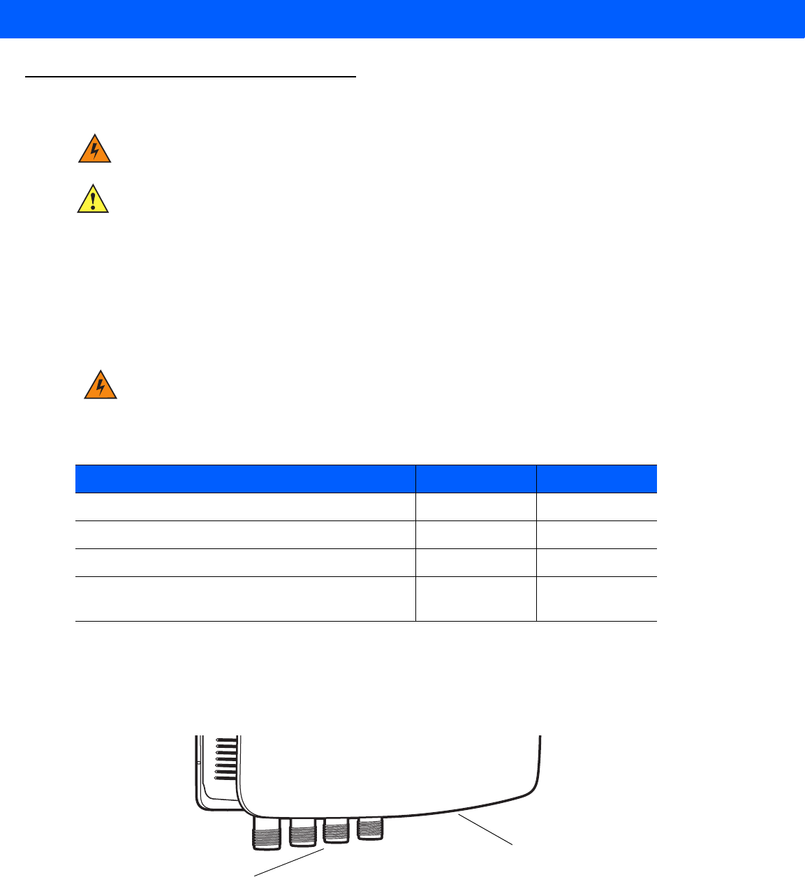
boot-up details.
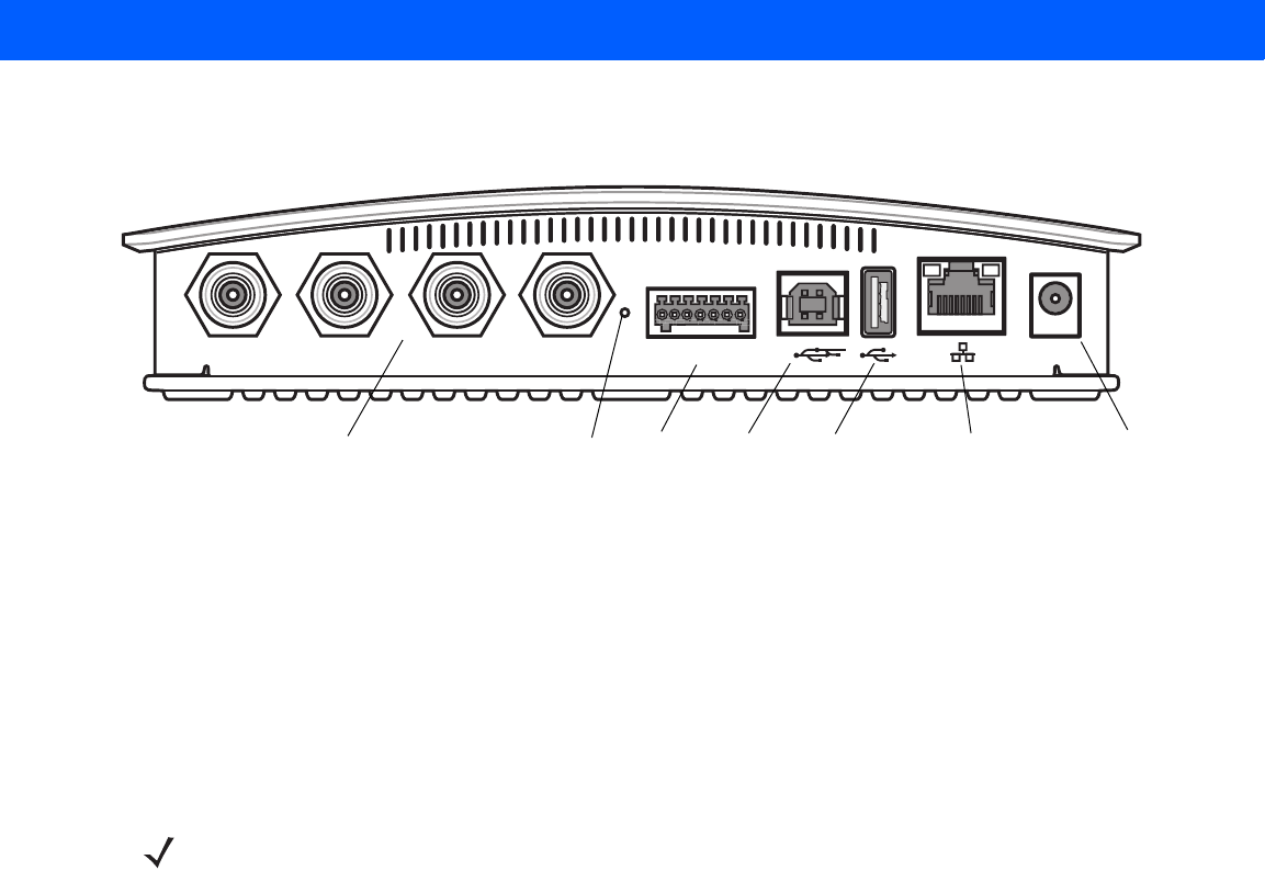
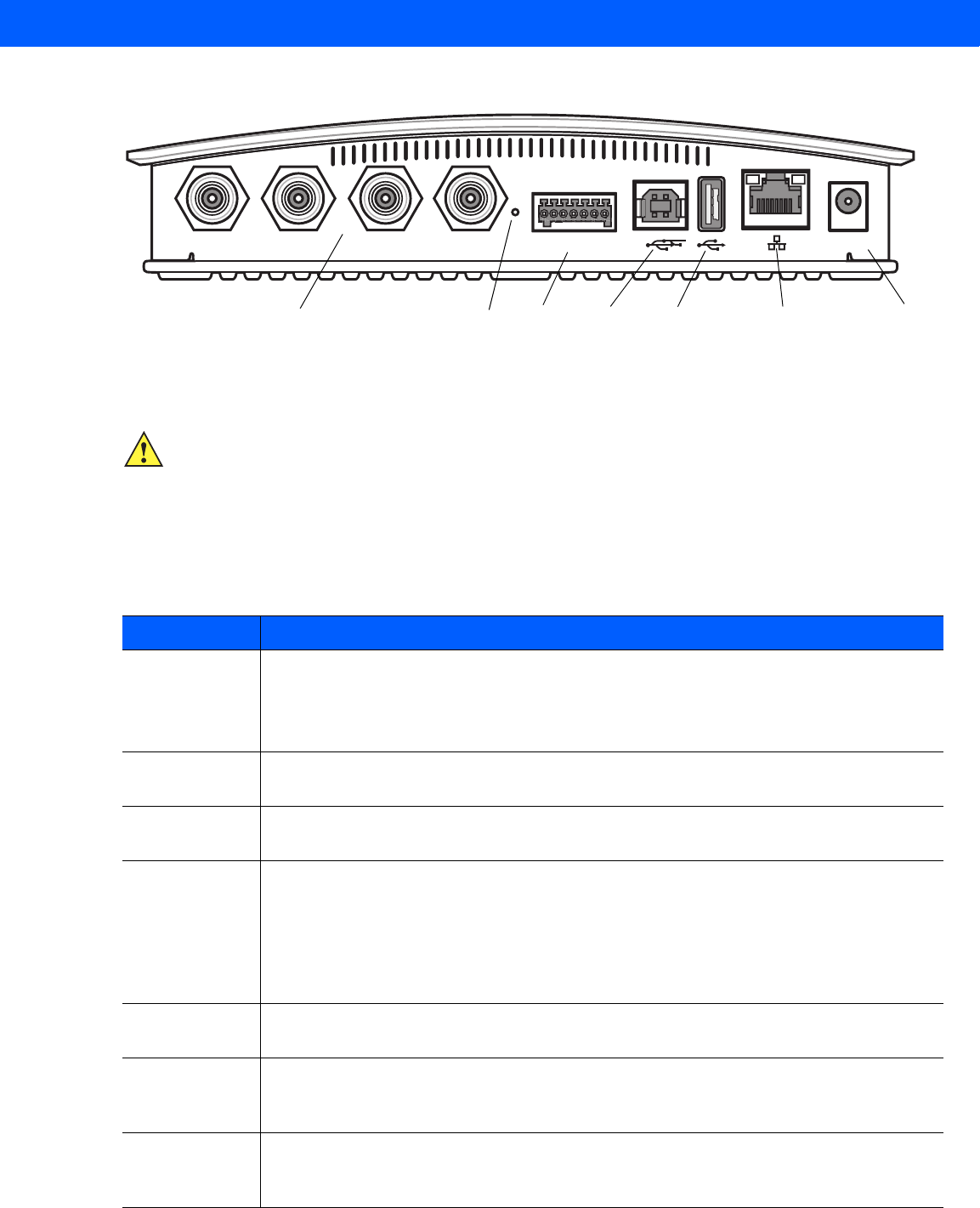
Figure 1-1
FX7500 RFID Reader Rear Panel Connections
Step 2, Connecting to the Reader
To connect via host name:
1. Open a browser. Recommended browsers are IE10 (disabling Compatibility View is recommended),
Chrome v29, and FireFox 24.
2. Enter the host name, printed on the host name label on the reader, in the browser
(e.g., http://fx7500cd3b0d) and press Enter. The User Login window appears and the reader is ready.
To connect using the USB port for network connection, see Motorola USB RNDIS Driver on page 3-6. The
default USB RNDIS IP address for the reader is 169.254.10.1
Port 1 Port 2 Port 3 Port 4 GPIO 24 VDC
Antenna Ports (Four Ports, Reverse TNC) USB-B
Client
Power
GPIO 10/100BaseT
Ethernet (with POE)
Reset USB-A
Host
NOTE Connect the reader to a network that supports host name registration and lookup to ensure the network
can access the reader using the host name. For instance, some networks can register hostnames
through DHCP. When first connecting to the reader, it is recommended to keep DHCP enabled in both the
PC and in the reader, although it is not guaranteed that hostname will work all the time. Use the host
name printed on the reader label, or construct it using the reader MAC address on the bottom of the
reader. The host name is a string with the prefix FX7500, followed by the last three MAC address octets.
For example, for a MAC address of 00:15:70:CD:3B:0D, use the prefix FX7500, followed by CD, 3B, and
0D, to create the host name FX7500CD3B0D. Enter http://FX7500CD3B0D in the browser address bar
to access the reader.
Quick Start 1 - 3
Step 3, First Time / Start-Up Login
When starting the reader for the first time:
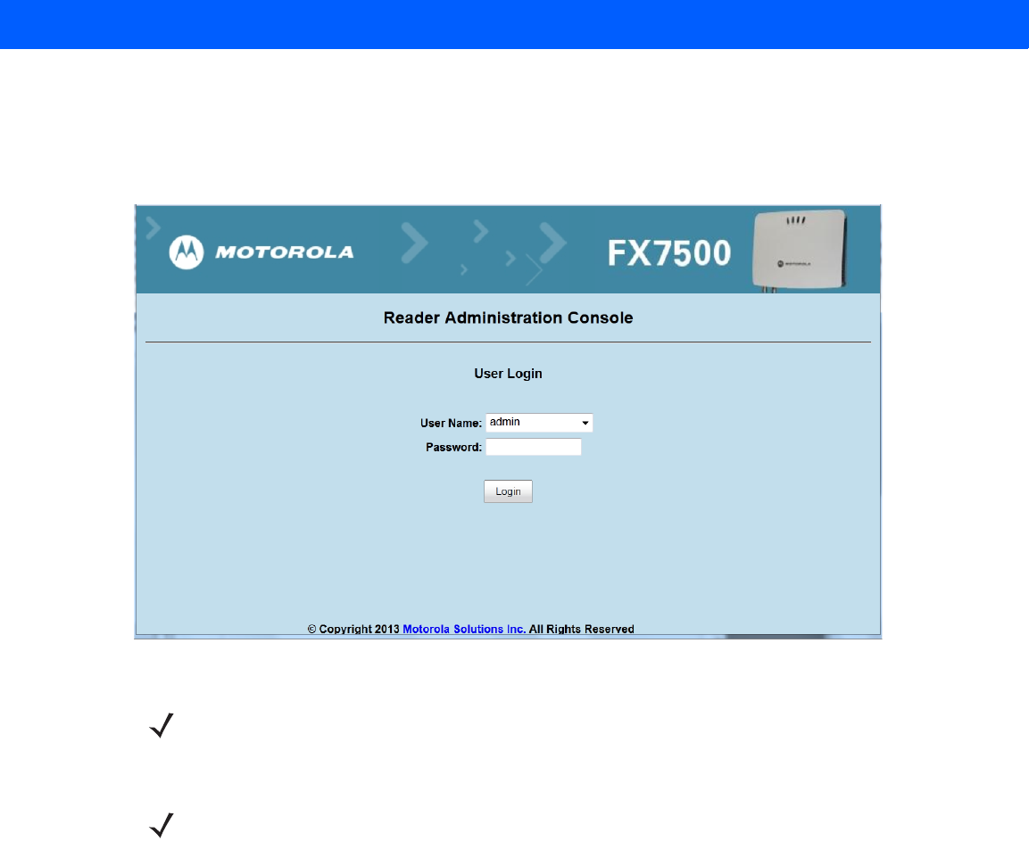
1. In the User Login window, enter admin in the User Name: field and enter change in the Password: field.
Figure 1-2
User Login Window
2. Click Login. The Region Configuration window appears.
NOTE Contact Motorola Solutions support if you forget the user ID and password.
See
Service Information on
page xi
.
NOTE The Region Configuration window does not appear for US reader configurations. For these models, the
Administrator Console main window appears.
See
Figure 4-1 on page 4-2
.
1 - 4 FX7500 RFID Reader Integrator Guide
Step 4, Set Region
Set the region of operation. Setting the unit to a different region is illegal.
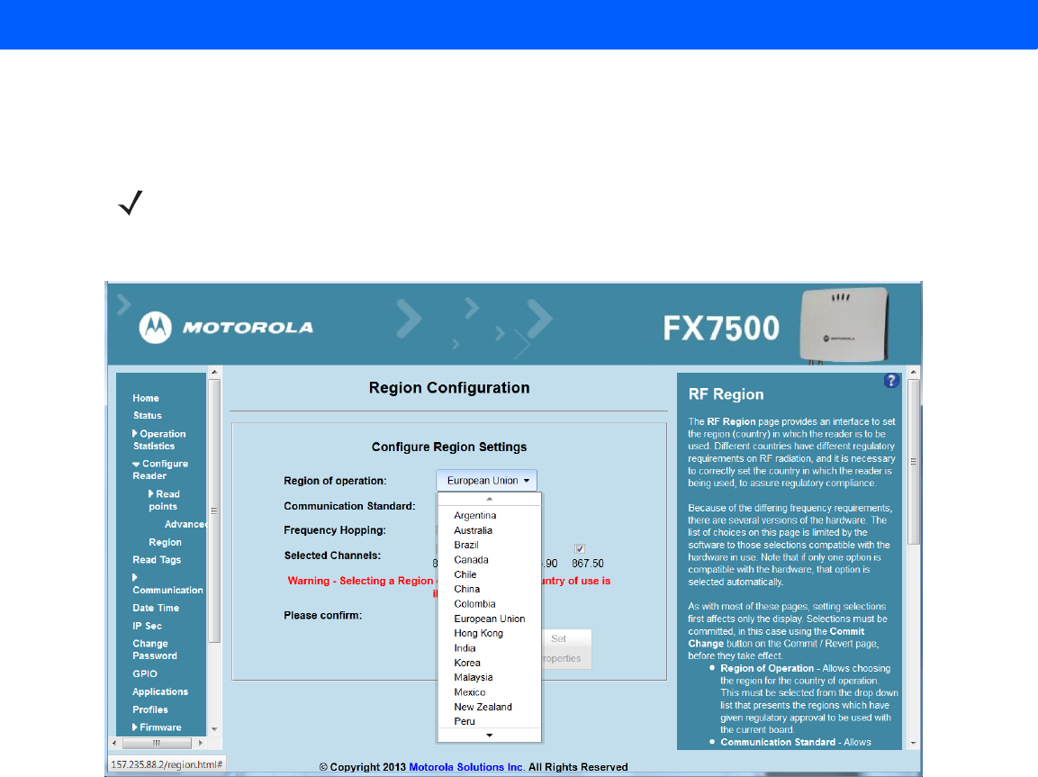
1. In the Configure Region Settings window, select the region from the drop-down menu.
Figure 1-3
Selecting the Region
2. Select the Communication Standard, if applicable.
3. Select Frequency Hopping, if applicable.
4. Select the appropriate channel(s), if applicable.
5. Select the I understand check box.
NOTE Region configuration is not available for readers configured to operate in the United States region (under
FCC rules). In this case, skip this step.
Quick Start 1 - 5
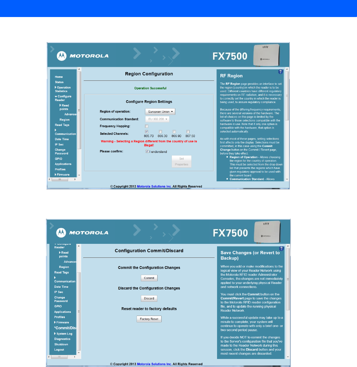
6. Select Set Properties to complete the region selection. The Operation Successful window appears.
Figure 1-4
Region Configuration, Operation Successful Window
7. Select Commit/Discard.
Figure 1-5
Commit/Discard Window
8. Click Commit to save the new region configuration and apply these changes to the reader configuration
file, or click Discard to discard the region configuration changes. When the commit completes, the Commit
Successful window appears.
1 - 6 FX7500 RFID Reader Integrator Guide
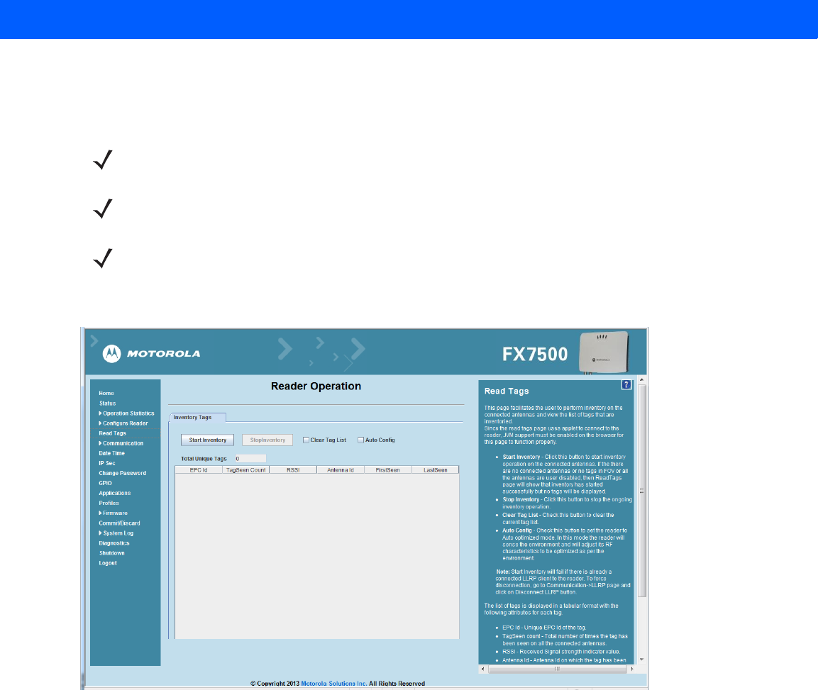
Step 5, Read Tags
Select Read Tags to view the Reader Operation window.
Figure 1-6
Read Tags Window
•
Click Start Inventory to initiate an on-demand scan on the connected antennas that are enabled.
•
Click Stop Inventory to stop the inventory operation.
•
Select the Clear Tag List check box to clear the current tag list.
The list of tags appears in a table with the following attributes for each tag:
•
EPC Id: Unique tag EPC ID.
•
TagSeen Count: Number of times the tag is identified on the specific antenna.
•
RSSI: Received Signal Strength Indication.
•
Antenna Id: Antenna ID on which the tag is seen.
•
FirstSeen time stamp: UTC time (in microseconds) when the tag was first seen.
•
LastSeen time stamp: UTC time (in microseconds) when the tag was last seen.
NOTE Enable Java JRE support on the browser for this page to function properly.
NOTE For security reasons browsers may block the Read Tags page. Look for a pop window that can be hidden
behind the browser or at the bottom of the screen (the taskbar in Windows) and allow the applet to run.
NOTE With older browsers, when upgrading/downgrading the FX7500, close the browser and re-open it to clear
the old version of files cached. If the java cache for applets is on, clear the cached applet before starting
the browser to use the Read Tags page.

CHAPTER 2 GETTING STARTED
Introduction
This chapter provides an overview of RFID technology and components, and describes the FX7500 reader and
its features.
RFID Technology Overview
RFID (Radio Frequency Identification) is an advanced automatic identification (Auto ID) technology that uses
radio frequency signals to identify tagged items. An RFID tag contains a circuit that can store data. This data
may be pre-encoded or can be encoded in the field. The tags come in a variety of shapes and sizes.
A typical RFID system consists of transponders (called tags), readers, and antennas. To read a tag the reader
sends out radio frequency waves (using attached antennas). This RF field powers and charges the tags, which
are tuned to receive radio waves. The tags use this power to modulate the carrier signal. The reader interprets
the modulated signal and converts the data to a format for computer storage. The computer application
translates the data into an understandable format.
Figure 2-1
RFID System Elements
Reader and Antenna
Host Computer
Physical/Network
Connection
RF Wave and
Response
Tags

2 - 2 FX7500 RFID Reader Integrator Guide
RFID Components
Motorola RFID solutions offer low cost, long read range, and a high read rate. These features provide real time,
end-to-end visibility of products and assets in the factory, distribution center, retail outlet, or other facility. A
typical Motorola RFID system consists of the following components:
•
Silicon based RFID tags that attach to retail products, vehicles, trailers, containers, pallets, boxes, etc.
•
Different antenna types to support applications such as dock door (area antennas) and conveyor.
•
Readers power and communicate with the tags for data capture and provide host connectivity for data
migration.
Tags
Tags contain embedded chips that store unique information. Available in various shapes and sizes, tags, often
called transponders, receive and respond to data requests. Tags require power to send data, and are available
with two power options:
•
Active Tags: typically powered by light-weight batteries and have limited life.
•
Passive Tags: the RFID reader generates an RF field that powers the tag. Passive tags are much lighter,
less expensive, and have a much longer life than active tags.
Antennas
Antennas transmit and receive radio frequency signals. A read point is the RF range of an antenna.
Readers
Readers communicate with the tags and can transfer the data to a host computer. Readers also provide
features such as filtering and tag writing. FX7500 readers read Gen2 (dense reader mode) RFID tags.
Getting Started 2 - 3
FX7500 RFID Readers
The Motorola FX7500 RFID readers are intelligent, C1G2 UHF RFID readers with RFID read performance that
provides real-time, seamless EPC-compliant tags processing. FX7500 RFID readers are designed for indoor
inventory management and asset tracking applications in large scale deployments. The readers can host
third-party customer-driven embedded applications.
FX7500 RFID readers are based on Motorola's strategic FX7500 reader platform and are easy to use, deploy,
and manage. The readers offer a variety of options for connecting to corporate networks using Ethernet or
USB connections. Features include:
•
ISO 18000-6C standard (EPC Class 1 Gen 2)
•
Dense reader mode capability
•
Enterprise-class performance
•
Application-specific setup for ease of installation
•
Power over Ethernet (POE) to eliminate the need for a power drop
•
SSL/SSH based security for secure data transmission
•
Linux operating system
•
Support for custom or third-party applications
•
Feature set for event and tag management
•
Support for NXP custom commands over LLRP
•
Radio mode support via LLRP v1.0.1
Figure 2-2
FX RFID Reader
2 - 4 FX7500 RFID Reader Integrator Guide
The reader provides a wide range of features that enable implementation of complete, high-performance,
intelligent RFID solutions.
FX7500 RFID reader configurations include either two or four
monostatic
antenna ports. The monostatic ports
are used only with monostatic antennas.
Versions and Kits
FX7500 RFID readers are available in a 2-port or 4-port version, individually (reader and mounting bracket) or
in a kit that includes the reader, mounting bracket, an antenna, and a power supply. For detailed kit information,
see FX7500 Kits on page A-1.
FX7500 RFID Reader
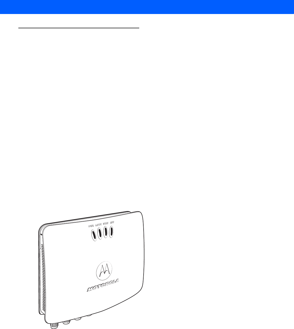
Figure 2-3
FX7500 RFID Reader
WARNING!For Mounting in Environmental Air Handling Space (EAHS): Do not install the Mounting
Bracket, Antenna, Cables, PSU, and PoE (Power Injector) in the EAHS unless they are suitable
for use in EAHS per UL 2043.
PWR ACTV STAT APP
Antenna Ports (Reverse TNC)
LEDs
Rear Panel
Getting Started 2 - 5
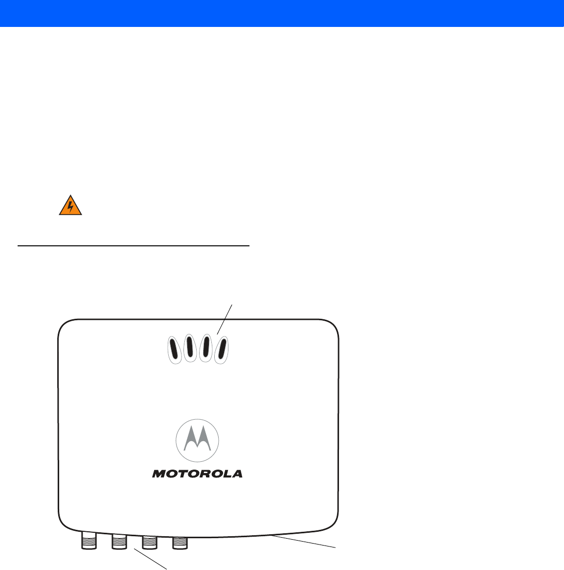
Figure 2-4
FX7500 RFID Reader Rear Panel Connections
FX7500 RFID Reader Rear Panel
Port 1 Port 2 Port 3 Port 4 GPIO 24 VDC
Antenna Ports (Four Ports, Reverse TNC) USB-B
Client
Power
GPIO 10/100BaseT
Ethernet (with POE)
Reset USB-A
Host
CAUTION Use only parts provided with the FX7500 RFID readers, or Motorola approved/recommended parts.
Substituting other cables or parts can degrade system performance, damage the reader, and/or void
the warranty.
Table 2-1
Rear Panel Descriptions
Port Description
Antenna Ports
(Reverse TNC) Two port version: Connect up to two antennas.
Four port version: Connect up to four antennas.
See
Table A-1 on page A-2
for the maximum antenna gains and RF output powers for both
US/Canada and EU. See
Connecting Antennas on page 3-4
for connection information.
Reset To reset the reader insert a paper clip into the reset hole, press and hold the reset button for
not more than 2 seconds. This resets the reader, but retains the user ID and password.
GPIO Insert a DE15 serial cable to connect to external devices. See
GPIO Interface Connection
on page 3-9
for more information.
USB Client The USB client port supports (by default) a network mode of operation. This enables a
secondary network interface as a virtual adapter over USB.
Use Visual Studio to use the USB port for development. Use a remote display tool to access
the Windows CE graphical interface.
Advanced users can create a custom communication protocol on the USB port.
See
USB
Connection on page 3-6
for connection information.
USB Host Use the USB host port to connect USB devices such as WiFi / Bluetooth over USB dongles
and flash memory drives.
10/100BaseT
Ethernet Insert a standard RJ45 Ethernet cable to connect to an Ethernet network with or without
POE capability, or to a local computer. See
Ethernet Connection on page 3-5
for
connection information.
Power DC connector connects to a Motorola approved power supply AC adapter (varies depending
on the country). Maximum power 24 VDC, 1.2 A. See
Powering the Reader on page 3-10
for connection information.
2 - 6 FX7500 RFID Reader Integrator Guide
FX7500 RFID Readers LEDs
The reader LEDs indicate reader status as described in Table 2-2. For the LED boot up sequence see System
Start-up/Boot LED Sequence on page 3-11.
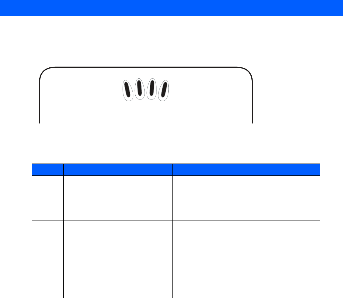
Figure 2-5
FX7500 RFID Readers LEDs
Table 2-2
LED Indications
LED Function Color/Status Description
PWR Power Off
Amber Solid
Red Flashing
Amber Solid
Green Solid
Reader is powered off
Booting
Firmware upgrade
Application initialization after booting
Reader is powered on and operational
ACTV Activity Off
Amber Flashing
Green Flashing
No RF operations
On for 500 mSec indicates another tag operation
On for 500 mSec indicates a tag is inventoried or read
STAT Status Off
Red Solid
Red Flashing
Green Flashing
No errors or GPIO events
Firmware update failure
On for 500 mSec indicates an error in RF operation
On for 500 mSec indicates a GPI event
APP Application Green/Red/Amber Controlled through RM
PWR ACTV STAT APP

Getting Started 2 - 7
FX7500 RFID Reader Features
Configuration and Upgrading
Use the Administrator Console to reconfigure the reader. See Chapter 4, Administrator Console. The reader
can also accept new firmware and configuration updates.
Tag Management
The Administrator Console provides the Read tags feature. See Read Tags on page 4-21. Use client
applications based on Motorola EMDK (Enterprise Mobility Development Kit) such as Power Session, or LLRP
(EPCGlobal Low Level Reader Protocol) for additional tag management operations such as Write, Lock,
Filtering, Event Management and Kill.
Device Management
Quick Backup and Recovery
Use a web browser to back up and restore reader configuration by downloading the configuration XML file. Use
the Administrator Console to download the file to the reader.
SNMP Integration
The reader can send real time notification of specific events and failures to an SNMP server.
Logging
The reader keeps a log of all system-related activities for security and troubleshooting. The log includes
time-stamped system activities such as login attempts and hardware failures. Use the log to pinpoint problems,
to facilitate quick resolution, and to identify administrators who may require additional training to prevent future
problems. See System Log on page 4-42.
Connection Options
The FX7500 provides flexibility for connecting to networks through an Ethernet connection or the USB client
port. The reader’s primary network interface is Ethernet. The Ethernet interface accesses each reader from
anywhere on the network using the unique host name or IP address.
Additionally, the USB client port supports (by default) a Network mode of operation. This enables a secondary
network interface as a virtual adapter over USB. The interfaces co-exist and if the Ethernet connection fails,
the application can switch to USB using a specific IP and can control the reader.
See Communications Connections on page 3-5. To use the USB port for network connection, see Motorola
USB RNDIS Driver on page 3-6.

2 - 8 FX7500 RFID Reader Integrator Guide

CHAPTER 3 INSTALLATION AND
COMMUNICATION
Introduction
This chapter includes the following FX7500 RFID reader installation and communication procedures:
•
Unpacking the Reader on page 3-1
•
Mounting and Removing the Reader on page 3-2
•Mounting Tips on page 3-2
•Mounting Using the Mounting Plate on page 3-2
•Direct Mounting (Without the Mounting Plate) on page 3-3
•
Connecting Antennas on page 3-4
•
Communications Connections on page 3-5
•Ethernet Connection on page 3-5
•USB Connection on page 3-6
•GPIO Interface Connection on page 3-9
•
Powering the Reader on page 3-10
•Powering the Reader via AC Power Supply on page 3-10
•Powering the Reader via Power-over-Ethernet (POE) on page 3-10
•
System Start-up/Boot LED Sequence on page 3-11
Unpacking the Reader
Remove the reader from the shipping container and inspect it for damage. Keep the shipping container, it is the
approved shipping container and should be used if the reader needs to be returned for servicing.
CAUTION FX7500 RFID readers must be professionally installed.
WARNING!For Mounting in Environmental Air Handling Space (EAHS): Any cables used to interconnect
to other equipment must be suitable for use in EAHS as per UL2043.
3 - 2 FX7500 RFID Reader Integrator Guide
Mounting and Removing the Reader
Mounting Tips
Mount the reader in any orientation. Consider the following before selecting a location for the FX7500 reader:
•
Mount the reader indoors, in operating range and out of direct sunlight, high moisture, and/or extreme
temperatures.
•
Mount the reader in an area free from electromagnetic interference. Sources of interference include
generators, pumps, converters, non-interruptible power supplies, AC switching relays, light dimmers, and
computer CRT terminals.
•
Mount the reader within 15 feet of the antennas.
•
Ensure that power can reach the reader.
•
The recommended minimum horizontal mounting surface width is 7 1/2 inches. However, the unit can
mount on surfaces as narrow as 6 inches (in locations where unit overhang is not an issue). For vertical
mounting the unit can mount on a surface as small as 6 inches by 6 inches.
•
Mount the reader onto a permanent fixture, such as a wall or a shelf, where it is not disturbed, bumped,
or damaged. The recommended minimum clearance on all sides of the reader is five inches.
•
Use a level for precise vertical or horizontal mounting.
Mounting Using the Mounting Plate
1. Position the mounting plate on a flat surface (wall or shelf). Position the release tab on the top. See Figure
3-1.
2. Mark the hole locations using the mounting plate as a guide. See Figure 3-1. Remove the mounting plate
and drill holes (appropriate for the surface material) at the marked locations.
WARNING!When installing the antenna ensure a minimum separation distance of 9.1 in (23 cm)
between the antennas and all persons.
WARNING!For Mounting in Environmental Air Handling Space (EAHS): Do not install the Mounting
Bracket in the EAHS.
NOTE For wood surfaces, drill two 1/8" diameter by 7/8" deep holes. For drywall/masonry surfaces, drill two
3/16" diameter by 7/8" deep (min) holes and install using the provided anchors.
Installation and Communication 3 - 3
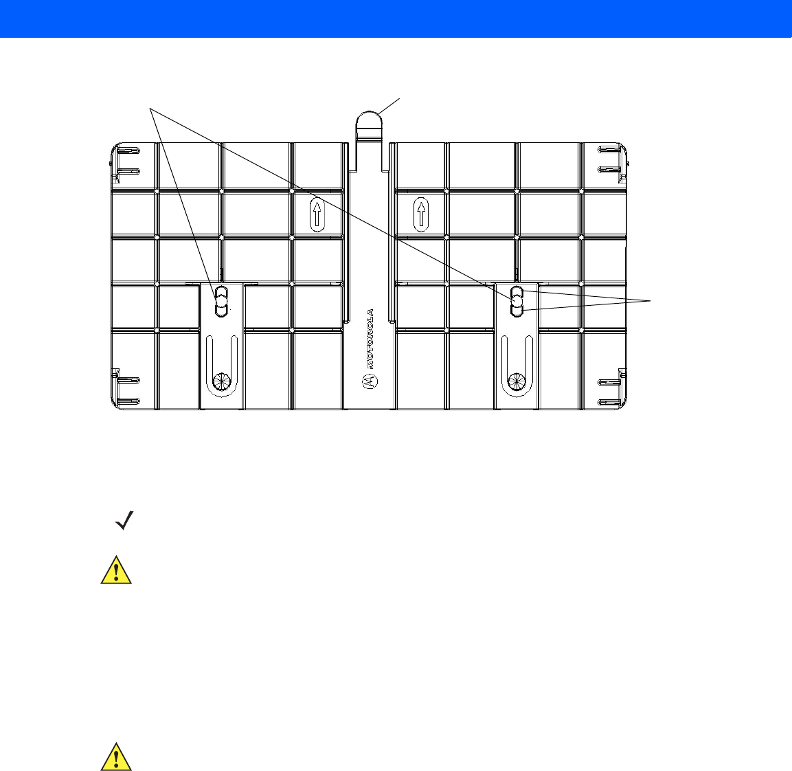
Figure 3-1
Mounting Plate, Front
3. Reposition the mounting plate over the mounting holes and secure using the supplied fasteners (as
appropriate for the surface material).
4. Position the reader by aligning the markers on the metal base plate and the wall bracket, with the key-slot
holes over the mounting screws. Gently slide the reader down to lock into place.
5. To remove the reader, press the release tab and slide the reader up while gently pulling out.
Direct Mounting (Without the Mounting Plate)
To mount the unit without using the mounting bracket:
1. Use the mounting bracket as a template to locate the holes, or locate and mark the holes on 4 3/16”
centers, +/- 1/32”.
2. For wood surfaces, drill two 1/8" diameter by 7/8" deep holes on 4.192" centers. For drywall/masonry
surfaces, drill two 3/16" diameter by 7/8" deep (min) holes on 4.192" centers and install using the provided
anchors.
3. Position the reader with the key-slot holes over the mounting screws and gently slide the reader down to
lock into place.
4. Adjust the screw head height to assure a snug fit. Or if the screws are accessible from the back, use
machine screws with a lock washer/nut and tighten the nut (from the back) to secure the reader.
Screw Head Stops
(4 typical)
Release Tab
Mounting Holes
NOTE Mount the reader with the cable connections up or down, depending on the installation requirements.
CAUTION Use a hand screw driver to install the mounting plate (do not use a power driver). Do not use
excessive torque, and tighten the screws so that they are just snug on the screw head stops (see
Figure 3-1). If the reader does not engage the mounting plate, loosen the screw(s) 1/8 to 1/4 turn and
try again.
CAUTION Not using the mounting plate can affect read performance at elevated temperatures. Also, if not using
the mounting plate, secure the reader to prevent it from coming off of the mounting screws.
3 - 4 FX7500 RFID Reader Integrator Guide
Connecting Antennas
To connect the antennas to the reader (see Figure 3-2):
1. For each antenna, attach the antenna reverse TNC connector to an antenna port.
2. Secure the cable using wire ties. Do not bend the cable.
Figure 3-2
FX7500 RFID Reader Antenna Connection
WARNING!When installing the antenna ensure a minimum separation distance of 9.1 in (23 cm) between
the antenna and all persons.
CAUTION Power off the reader before connecting antennas. See Powering the Reader on page 3-10. Never
disconnect the antennas while the reader is powered on or reading tags. This can damage the reader.
Do not turn on the antenna ports from a host when the antennas are not connected.
Maximum antenna gain (including any cable loss) cannot exceed 6 dBiL.
When mounting the antennas outside the building, connect the screen of the coaxial cable to earth
(ground) at the entrance to the building. Perform this in accordance with applicable national electrical
installation codes. In the U.S., this is required by Section 820.93 of the National Electrical Code,
ANSI/NFPA 70.
WARNING!For Mounting in Environmental Air Handling Space (EAHS): Do not install Antennas and
Antenna Cables in the EAHS unless they are suitable for use in EAHS as per UL 2043.
Table 3-1
Antenna Gain and Radiated Power
FX7500 US EU
Max Conducted RF Power at Antenna Input + 30.0 dBm +29.2 dBm
Max Antenna Gain Allowed + 6dBiL + 5.5 dBiL
Max Radiated Power Allowed 4W EIRP 2W ERP
Antenna Type Circularly
Polarized Plate N/A
Antenna Ports (Reverse TNC)
Rear Panel

Installation and Communication 3 - 5
Communications Connections
Use a standard Ethernet connection, a standard POE, or POE + Ethernet connection to connect the FX7500
reader to a host or network.
Ethernet Connection
The reader communicates with the host using an Ethernet connection (10/100Base-T Ethernet cable). This
connection allows access to the Administrator Console, used to change reader settings and control the reader.
With a wired Ethernet connection (10/100Base-T cable), power the FX7500 reader using either the reader
Motorola AC power supply, or by Power-Over-Ethernet through the Ethernet cable.
Ethernet: Power through AC Outlet
The FX7500 reader communicates to the host through a 10/100Base-T Ethernet cable and receives power
through a Motorola AC power supply.
1. Route the Ethernet cable.
2. Route the power cable.
3. Terminate the Ethernet cable according to Table A-2 on page A-4.
4. Connect the Ethernet cable to the LAN port on the FX7500 reader. See Figure 2-4 on page 2-5.
5. Connect the other end of the Ethernet cable to the host system LAN port.
6. Connect the Motorola AC power supply to a wall outlet.
7. Insert the power supply barrel connector into the FX7500 reader power port. See Figure 2-4 on page 2-5.
8. Verify that the unit booted properly and is operational. See System Start-up/Boot LED Sequence on page
3-11.
9. On a networked computer, open an internet browser and connect to the reader. See Connecting to the
Reader on page 4-3.
10. Log in to the Administrator Console. See Administrator Console Login on page 4-6.
Ethernet: Power through Standard POE or POE+
The POE installation option allows the FX7500 reader to communicate and receive power on the same
10/100Base-T Ethernet cable.
1. Insert the POE Ethernet connector on the RJ45 Ethernet cable into the reader 10/100BaseT Ethernet port.
See Figure 2-4 on page 2-5.
2. Connect the other end of the cable to an Ethernet network with POE capability.
3. Verify that the reader booted properly and is operational. See System Start-up/Boot LED Sequence on
page 3-11.
4. On a networked computer, open an internet browser and connect to the reader. See Connecting to the
Reader on page 4-3.
5. Log in to the Administrator Console. See Administrator Console Login on page 4-6.
CAUTION Do not connect to PoE networks outside the building.

3 - 6 FX7500 RFID Reader Integrator Guide
To connect to a network that is not POE capable:
1. Terminate the Ethernet cable according to Table A-2 on page A-4.
2. Connect the Ethernet cable to the FX7500 reader 10/100BaseT Ethernet port. See Figure 2-4 on page 2-5.
3. Connect the other end of the Ethernet cable to a POE power injector.
4. Connect a patch cable from the POE power injector to the host system LAN port.
5. Verify that the unit booted properly and is operational. See System Start-up/Boot LED Sequence on page
3-11.
6. On a networked computer, open an internet browser and connect to the reader. See Connecting to the
Reader on page 4-3.
7. Log in to the Administrator Console. See Administrator Console Login on page 4-6.
USB Connection
The USB client port supports (by default) a Network mode of operation. This enables a secondary network
interface as a virtual adapter over USB. The interfaces co-exist and if the Ethernet connection fails, the
application can switch to USB using a specific IP and can control the reader. To use the USB port for network
connection, install the Motorola USB RNDIS Driver on the Windows XP PC or follow the instructions to install
the Microsoft RNDIS driver for Windows 7 below.
To connect the FX7500 to the host PC, insert a USB cable into the USB client port on the reader. See Figure
2-4 on page 2-5. Connect the other end of the cable to a USB port on the host PC.
Motorola USB RNDIS Driver
To use the USB port for network connection, install the Motorola USB Remote Network Device (RNDIS) driver
and enable the driver on the FX7500. The Motorola RNDIS driver supports 32-bit version operating systems
Windows XP, Windows Vista, Windows 7, and Windows Server 2008. For Windows 7 32-bit and 64-bit
systems, it is recommend to use Microsoft RNDIS driver (see Microsoft RNDIS Driver for Windows 7 on page
3-7).
To install the RNDIS driver on the host.
1. Download the installer file Motorola RNDIS.msi from http://www.motorolasolutions.com/support to the host
PC.
2. Select this file on the host PC to install the host side drivers for using the USB Remote Network Device
Interface on the FX7500.
3. Connect a USB cable between the host and the reader. The Welcome to the Found New Hardware Wizard
screen appears.
4. Select the No, not this time radio button and click Next.
5. Select the default option Install Software Automatically (Recommended).
6. In the Hardware Installation pop-up window, select Continue Anyway.
7. Select Finish to complete the installation. This assigns the host an auto-configured IP address. The
network is now ready to use and the reader’s IP address is fixed to 169.254.10.1.
Installation and Communication 3 - 7
Microsoft RNDIS Driver for Windows 7
If using Windows 7:
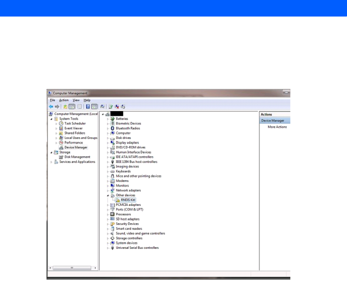
1. After connecting a USB cable between the PC and reader, the RNDIS driver automatically installs. If it
does not, right-click on Computer and select Manage. From System Tools, select Device Manager.
Under Other Devices, look for an entry for RNDIS with an exclamation icon indicating that the driver was
not installed.
Figure 3-3
Computer Management Window
2. Right-click the icon and select Update Driver Software. Search for the device driver software by clicking
on Browse my computer for driver software.
3. Select Let me pick from a list of device drivers on my computer.
3 - 8 FX7500 RFID Reader Integrator Guide
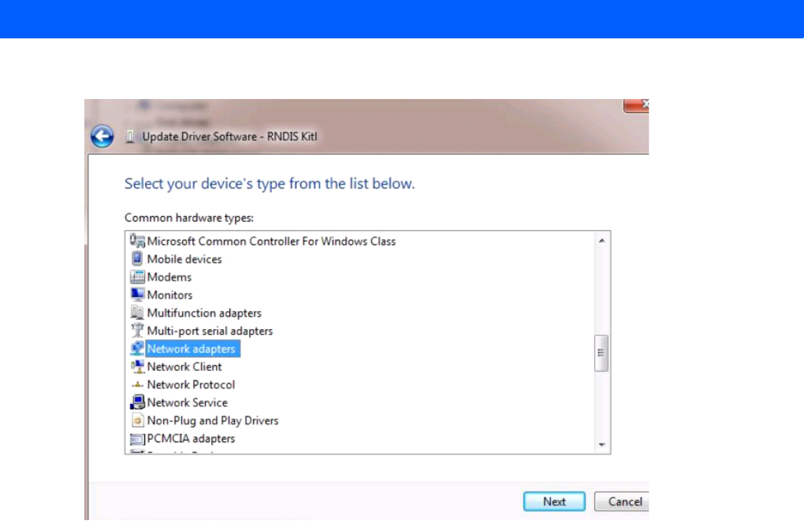
4. Select Network adapters.
Figure 3-4
Selecting Device Type
5. Select Microsoft Corporation from the manufacturer list.
6. Under Network Adapter, select Remote NDIS Compatible Device, and click Next.
After installation, the PC recognizes the reader as an RNDIS device. The PC obtains the IP address
169.254.10.102, and the reader is reachable at the IP address 169.254.10.1.
Sample Implementation
This implementation assumes that only one FX7500 reader is connected to a host PC via USB. This feature
does not function with multiple readers connected to the host. Motorola recommends disabling any other
network interface on the PC.
Use an application that uses RFID3 APIs such as Power Session, or use an LLRP application to connect to the
reader to read tags.
1. The primary RFID server connects to the FX7500 via the Ethernet interface.
2. The host PC connects to the FX7500 via the USB port. An application on the host PC monitors
communication between the primary RFID server and FX7500 reader.
3. When the application on the host PC detects a communication failure between the primary RFID server
and the reader, it connects to and controls the reader using the USB virtual interface.
Installation and Communication 3 - 9
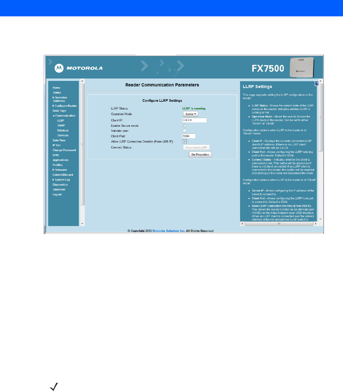
4. The FX7500 listens on the USB virtual interface on a fixed port (49152) as well as on the standard LLRP
port (5084). To enable this, select the Allow LLRP Connection Override check box in Configure LLRP
Settings console window.
Figure 3-5
Communication / Configure LLRP Settings Window
Only one LLRP session can be active on the reader, either through the primary Ethernet interface or through
the virtual network over USB interface.
If connection is active on one interface, a subsequent connection attempt on a second interface disconnects
the first. The second connection attempt always prevails and creates a new session.
GPIO Interface Connection
This pluggable terminal block type allows connecting individual wires independently. A single connector
accommodates both inputs and outputs. See Table A-5 on page A-6 for pinout information.
GPIO signals allow some flexibility. Inputs are pulled up within the reader to +5 VDC and can be shorted to
ground to pull them low. This allows driving them directly via simple relay or switch contacts. Alternatively, 5V
logic can drive inputs. In the logic low state, the current sourced from the reader is approximately 3 mA, so
standard gates in most logic families can drive them. Current flow in the high state is negligible. When the
equipment uses an external +24 VDC power supply, a +24 VDC connection is provided. This output is not
available when an external 24 VDC supply is not present.
The general purpose outputs are open-drain drivers, pulled up to 5V. Each output can withstand voltages up to
+30 VDC but should not be driven negative. For best results use the +24 VDC supply as a source of external
current and use the outputs directly to drive 24V relays, indicator lamps, etc., wired between the 24V supply
NOTE Do not connect the +24 VDC output directly to either general purpose input that tolerates voltages in
excess of 5V but is designed to operate optimally within the range of 0 to +5 VDC.

3 - 10 FX7500 RFID Reader Integrator Guide
and individual general purpose outputs. Although each output can sink up to 1A, the maximum current that can
be drawn from the internal 24V supply is 1A, so use an external power supply if the current requirement
exceeds this. Note that the state of the general purpose outputs is inverted, e.g., driving a GPO line high at the
processor pulls the corresponding output low.
Powering the Reader
Powering the Reader via AC Power Supply
The Motorola approved AC power supply connects to the power port on the FX7500 reader using a locking
connector (see Figure 2-4 on page 2-5). The power supply is compatible with:
•
120V 60 Hz (North America)
•
230V 50 Hz (International excluding Japan)
•
100V 50/60 Hz (Japan).
1. Insert the power supply barrel connector into the reader power port (see Figure 2-4 on page 2-5). Rotate
the connector to lock it in place.
2. Apply power to the power supply. The green Power LED stays on to indicate the reader is powered and
ready. See System Start-up/Boot LED Sequence on page 3-11.
To power down the reader, unplug the power supply from its power source. The green Power LED turns off to
indicate that the device is off and the system is not operational. Remove the connector from the reader power
port.
Powering the Reader via Power-over-Ethernet (POE)
Connect the reader to either a standard POE or POE+ injectors.
1. Insert the POE Ethernet connector on the RJ45 Ethernet cable into the reader 10/100BaseT Ethernet port.
See Figure 2-4 on page 2-5.
2. Connect the other end of the cable to an Ethernet network with POE capability. See System Start-up/Boot
LED Sequence on page 3-11.
To power down the reader, remove the Ethernet cable from the network. The green Power LED turns off to
indicate that the device is off and the system is not operational. Remove the connector from the 10/100BaseT
Ethernet port.
CAUTION Connect the antennas before supplying power to the reader.
WARNING!For Mounting in Environmental Air Handling Space (EAHS): Do not install Power Supplies and
PoE (Power Injector) in the EAHS unless they are suitable for use in EAHS as per UL 2043.

Installation and Communication 3 - 11
LED Sequences
System Start-up/Boot LED Sequence
See Figure 2-5 on page 2-6 for LED locations. During system start-up:
1. All LEDs turn on for a few seconds when power is applied to the reader.
2. All LEDs turn off and the PWR LED turns amber.
3. The PWR LED turns green to indicate successful RFID application initialization.
4. When the sequence completes, the green PWR LED remains on and all other LEDs are off.
PWR LED Sequence to Indicate IPv4 Status after Booting
After the RFID application initializes:
1. The PWR LED turns green for 5 seconds to indicate success (following the sequence from System
Start-up/Boot LED Sequence).
2. The reader checks the eth0 IPv4 address and indicates the IPv4 status using the LEDs:
•
If the reader has a DHCP address, the PWR LED blinks green for 3 seconds.
•
If the reader has static IP address, the PWR LED blinks amber 3 seconds.
•
If the reader has an IP address from zero-configuration networking algorithm, the PWR LED blinks red
for 3 seconds.
•
If the reader doesn't have valid IP, the PWR LED blinks amber and green using a 90-second timeout to
indicate that it is waiting to acquire an IP address.
•If it obtains a valid IP within the timeout period, the reader indicates the status as described above.
•If the timeout expires before the reader obtains an IP, the PWR LED stops blinking.
3. The PWR LED again turns solid green.
Reset to Factory Defaults LED Sequence
Holding the reset button for 8 seconds resets the reader to the factory default configuration.
1. All LEDs turn on as usual when you press and hold the reset button.
2. The PWR LED blinks amber when the reset button is held.
3. The PWR LED blinks green fast 5 times to indicate that the reader detects a reset operation.
4. Release the reset button to reset the reader to factory defaults.
LED Sequence for Software Update Status
1. The PWR LED blinks red during the software update process.
2. After reset, the STAT LED blinks red if the radio module requires a firmware update.

3 - 12 FX7500 RFID Reader Integrator Guide
Reading Tags
After the reader powers up, test the reader. See System Start-up/Boot LED Sequence on page 3-11.
1. Enable tag reading using the web-based Administrator Console (see Read Tags on page 4-21) or control
the reader through a real-time application such as Power Session.
2. Present a tag so it is facing the antenna and slowly approach the antenna until the activity LED turns
green, indicating that the reader read the tag. See Figure 2-5 on page 2-6. The distance between the tag
and the antenna is the approximate read range.
NOTE For optimal read results, do not hold the tag at an angle or wave the tag, as this can cause the read
distance to vary.